EP4201807B1 - Procédé et dispositif de réduction de la chute de condensation sur les surfaces intérieures d'un revêtement extérieur d'avion et de composants adjacents - Google Patents
Procédé et dispositif de réduction de la chute de condensation sur les surfaces intérieures d'un revêtement extérieur d'avion et de composants adjacents Download PDFInfo
- Publication number
- EP4201807B1 EP4201807B1 EP21216430.5A EP21216430A EP4201807B1 EP 4201807 B1 EP4201807 B1 EP 4201807B1 EP 21216430 A EP21216430 A EP 21216430A EP 4201807 B1 EP4201807 B1 EP 4201807B1
- Authority
- EP
- European Patent Office
- Prior art keywords
- air
- air gap
- insulation
- aircraft
- line
- Prior art date
- Legal status (The legal status is an assumption and is not a legal conclusion. Google has not performed a legal analysis and makes no representation as to the accuracy of the status listed.)
- Active
Links
Images
Classifications
-
- B—PERFORMING OPERATIONS; TRANSPORTING
- B64—AIRCRAFT; AVIATION; COSMONAUTICS
- B64D—EQUIPMENT FOR FITTING IN OR TO AIRCRAFT; FLIGHT SUITS; PARACHUTES; ARRANGEMENT OR MOUNTING OF POWER PLANTS OR PROPULSION TRANSMISSIONS IN AIRCRAFT
- B64D13/00—Arrangements or adaptations of air-treatment apparatus for aircraft crew or passengers, or freight space
- B64D13/06—Arrangements or adaptations of air-treatment apparatus for aircraft crew or passengers, or freight space the air being conditioned
-
- B—PERFORMING OPERATIONS; TRANSPORTING
- B64—AIRCRAFT; AVIATION; COSMONAUTICS
- B64C—AEROPLANES; HELICOPTERS
- B64C1/00—Fuselages; Constructional features common to fuselages, wings, stabilising surfaces or the like
- B64C1/06—Frames; Stringers; Longerons ; Fuselage sections
- B64C1/066—Interior liners
- B64C1/067—Interior liners comprising means for preventing icing or condensation conditions
-
- B—PERFORMING OPERATIONS; TRANSPORTING
- B64—AIRCRAFT; AVIATION; COSMONAUTICS
- B64D—EQUIPMENT FOR FITTING IN OR TO AIRCRAFT; FLIGHT SUITS; PARACHUTES; ARRANGEMENT OR MOUNTING OF POWER PLANTS OR PROPULSION TRANSMISSIONS IN AIRCRAFT
- B64D13/00—Arrangements or adaptations of air-treatment apparatus for aircraft crew or passengers, or freight space
- B64D13/06—Arrangements or adaptations of air-treatment apparatus for aircraft crew or passengers, or freight space the air being conditioned
- B64D13/08—Arrangements or adaptations of air-treatment apparatus for aircraft crew or passengers, or freight space the air being conditioned the air being heated or cooled
-
- B—PERFORMING OPERATIONS; TRANSPORTING
- B64—AIRCRAFT; AVIATION; COSMONAUTICS
- B64D—EQUIPMENT FOR FITTING IN OR TO AIRCRAFT; FLIGHT SUITS; PARACHUTES; ARRANGEMENT OR MOUNTING OF POWER PLANTS OR PROPULSION TRANSMISSIONS IN AIRCRAFT
- B64D13/00—Arrangements or adaptations of air-treatment apparatus for aircraft crew or passengers, or freight space
- B64D13/06—Arrangements or adaptations of air-treatment apparatus for aircraft crew or passengers, or freight space the air being conditioned
- B64D2013/0603—Environmental Control Systems
- B64D2013/0662—Environmental Control Systems with humidity control
Definitions
- the invention relates to a method for reducing condensate precipitation on the inner surfaces of an aircraft outer skin and adjacent components, wherein the condensate precipitation is reduced by supplying dry air into an upper region of an air gap extending between the upper region and a lower region between the aircraft outer skin and an insulation arranged between a cabin wall and the aircraft outer skin.
- the invention also relates to a device for carrying out this method.
- the dry air supplied to the air gap between the aircraft outer skin and the insulation is supplied to the air gap via lines and flow control valves connected to the air conditioning system and a plurality of air outlet nozzles distributed in the air gap, whereby an air pressure higher than the air pressure prevailing in the cabin is formed in the air gap during cruising flight, which air pressure is The stack effect prevents cabin air from overflowing through the insulation into the air gap.
- the use of compressor bleed air and its treatment in an air conditioning system that also supplies cabin air to obtain the dry air supplied to the air gap requires increased air conditioning capacity, increased weight, and higher air conditioning costs due to the required increase in capacity, and thus higher energy consumption of the aircraft.
- the US 2021/0122476 A1 A method for reducing condensate formation on the inner surfaces of an aircraft's outer skin and adjacent components is known.
- This method involves blowing dry air conditioned in an air conditioning system into a space above the cabin ceiling (the "crown region") via ducts and controllable valves. Air conditioned in this or a separate air conditioning system is blown into the cabin from these or separate ducts, either simultaneously or alternately with the air blown into the upper space.
- the dry air blown into the space above the cabin ceiling is also provided by an air conditioning system, which in turn is fed with compressor bleed air.
- the object of the invention is to design the method described above for reducing condensate precipitation on the inner surfaces of an aircraft outer skin and adjacent components in such a way that the extraction of dry air, which extends into the upper region of the air gap extending between the upper region and a lower region between the aircraft outer skin and an insulation arranged between the cabin wall and the aircraft outer skin, takes place with lower expenditure on equipment and energy than before, whereby the method can be taken into account not only in the construction of new aircraft but also in the retrofitting of existing aircraft. A device for carrying out this method should also be specified.
- the object of the invention is achieved with regard to the method in that, according to the characterizing part of claim 1, the dry air is obtained by suction from the lower region of the air gap and is guided in one or more lines to the upper region of the air gap, where it is allowed to enter the air gap again.
- the object of the invention is achieved in that, according to the characterizing part of claim 6, the line or lines has or have one or more inlet openings at the lower region of the air gap, through which dry air in the lower region of the air gap can be sucked out, and in that the line or lines is or are connected to one or more fans which, during operation, generate or generate a pressure difference in the line or lines which moves the dry air from the inlet opening or openings to the outlet opening or openings.
- the invention is based on the observation that during flight, warm and humid air from the cabin flows into the upper area of the air gap through the non-airtight cabin wall and the air-permeable insulation. This is because there is a temperature gradient between the cabin and the upper area of the air gap, which leads to a thermally induced pressure difference, which causes this air flow. Typically, this air flowing into the air gap has a temperature of about 20°C and a Relative humidity (RH) of approximately 10%.
- RH Relative humidity
- During flight low outside temperatures prevail, which also cool the aircraft's outer skin and neighboring components behind the insulation. The air flowing into the air gap also cools. Since cold air has a higher density, it flows downward behind the insulation, where it would escape from the insulation again if it were not extracted according to the invention.
- the air flowing downward behind the insulation is dry, having been dehumidified by condensation on the cold aircraft's outer skin and the cold neighboring components.
- the idea behind the invention is to extract this air from the lower area of the air gap and reinject it at the top, particularly at areas requiring protection, thus creating a circulation of dry air.
- the lower area of the air gap, where the dry air is extracted, represents a "free" or at least "cheap" source of dry air.
- An advantage of the method according to the invention is that the use of the aircraft outer skin as a dehumidification unit and the extraction of dehumidified air is more energy-efficient than the known solutions in which the air is actively dehumidified or fresh bleed air from the engine is used.
- the use of one or more fans in the device according to the invention for carrying out the method is advantageous because a fan typically requires only a few watts, whereas mechanical dehumidification is associated with considerable effort due to the phase change and the already relatively dry cabin air, which has a relative humidity of approximately 10% RH.
- Fresh air from outside, which has a temperature of approximately -50°C, is also an "expensive" source of dry air, as it must first be compressed to cabin pressure and then conditioned.
- the reduction in condensate precipitation on the cold aircraft outer skin and the adjacent cold components achieved by the method according to the invention also reduces the risk of ice formation, which melts when the aircraft outer skin and the adjacent components become warm again and turns into water that can drip uncontrollably into the cabin and onto the passengers (keyword: "rain in the plane").
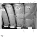
- insulation 1 in the form of a mat is located in the frame fields 2 between adjacent frames 3 of an aircraft (not shown in detail).
- the insulation is arranged between the cabin wall (not shown) and the invisible aircraft outer skin, with an invisible air gap being formed between the insulation 1 and the aircraft outer skin, which other components adjacent to the aircraft outer skin, such as the frames 3, also border on.
- a schematically illustrated duct network 4 consisting of several duct sections in the form of hoses serves to convey dry air from a lower region of the air gap to the upper region of the air gap.
- the duct network 4 has a plurality of first duct sections 5 which are guided through passages in the insulation 1 to the lower region of the air gap and have air inlet openings there (not shown).
- the duct network 4 also has second duct sections, which include a collecting duct 6 and a distribution duct 7.
- the first line sections 5 are connected to the collecting line 6 via multi-way valves (not shown), and the distribution line 7 is connected to several third line sections 8, which are each led through passages in the insulation 1 to the upper region of the air gap, where they have air outlet openings (not shown).
- An intermittently operated fan 9 has its inlet side connected to the collecting line 6 and its outlet side connected to the distribution line 7.
- the line network 4 is located largely in the space between the insulation 1 and the cabin wall.
- the fan 9 is also arranged there. Alternatively, however, it could also be arranged in a space above the cabin ceiling for reasons of space.
- each frame section 2 a first line section 5 and a third line section 8 are arranged.
- the arrangement of the first and third line sections 5, 8 with respect to the frame sections 2 can also be different, for example for reasons of space or for reasons of more effective air extraction or injection.
- fan 9 When fan 9 is switched on, it creates a pressure difference in the duct network 4, which causes dry air in the lower area of the air gap to be drawn into the inlet openings of the first duct sections 5 and moved via the collecting duct 6 and the distribution duct 7 to the third power sections 8, where it is blown back into the upper area of the air gap via their outlet openings.
- fan 9 instead of one fan 9, multiple fans can be used if necessary.
- the fan(s) are switched on and off depending on the temperature. For example, the fan(s) are switched on when the outside temperature during flight drops below approximately -7°C, approximately -9°C, or approximately -5°C.
- the condensation problem only occurs when the temperature of the outer skin falls below the dew point of the cabin air.
- the cabin air typically has a relative humidity of 10-15% at 23°C during flight. This corresponds to a dew point temperature of approximately -7°C.
- the air circulation system is only activated below this temperature.
- the control can be achieved with an on/off switch that activates the system with a fixed flow rate when the temperature falls below a certain threshold.
Landscapes
- Engineering & Computer Science (AREA)
- Aviation & Aerospace Engineering (AREA)
- Mechanical Engineering (AREA)
- Health & Medical Sciences (AREA)
- General Health & Medical Sciences (AREA)
- Pulmonology (AREA)
- Central Air Conditioning (AREA)
- Drying Of Solid Materials (AREA)
Claims (15)
- Procédé de réduction de la perte de condensation sur les surfaces intérieures d'un revêtement extérieur d'un avion,dans lequel la perte de condensation est réduite par amenée d'air sec vers une zone supérieure d'un interstice d'air s'étendant entre la zone supérieure et une zone inférieure et situé entre le revêtement extérieur de l'avion et un isolant (1), l'isolant étant disposé entre une paroi de la cabine et le revêtement extérieur de l'avion,caractérisé en ce que l'air sec est récupéré par aspiration hors de la zone inférieure de l'interstice d'air et est guidé dans un ou plusieurs conduits vers la zone supérieure de l'interstice d'air, où il entre à nouveau dans l'interstice d'air.
- Procédé selon la revendication 1,
caractérisé en ce que l'air sec est aspiré en plusieurs points de sortie de la zone inférieure de l'interstice d'air, espacés dans la direction longitudinale de l'avion, et est autorisé à entrer à nouveau dans la zone supérieure de l'interstice d'air en plusieurs points d'entrée de la zone supérieure de l'interstice d'air, espacés dans la direction longitudinale de l'avion, l'air sec étant guidé entre les points de sortie et d'entrée par un réseau de conduits (4) qui présente lesdits plusieurs conduits et dans lequel est générée une différence de pression déplaçant l'air sec des points de sortie vers les points d'entrée. - Procédé selon la revendication 2,caractérisé en ce que, à chaque point de sortie, un flux volumique d'air sec compris entre 0,7 l/s et 1,4 l/s est respectivement aspiré hors de l'interstice d'air, et/ouen ce que, à chaque point d'entrée, un flux volumique d'air sec compris entre environ 0,7 l/s et environ 1,4 l/s entre respectivement dans l'interstice d'air.
- Procédé selon l'une des revendications 1 à 3,
caractérisé en ce que l'aspiration d'air sec hors de la zone inférieure de l'interstice d'air et/ou l'amenée d'air sec vers la zone supérieure de l'interstice d'air est ou sont intermittentes. - Procédé selon l'une des revendications 1 à 4,caractérisé en ce que l'amenée de l'air sec vers la zone supérieure de l'interstice d'air ne se fait qu'à une température extérieure prédéterminée de l'air entourant le revêtement extérieur de l'avion, ouen ce que l'amenée de l'air sec vers la zone supérieure de l'interstice d'air ne se fait qu'à une température extérieure de l'air entourant le revêtement extérieur de l'avion d'environ 0 °C ou moins ou d'environ -7 °C ou moins.
- Dispositif pour la mise en œuvre du procédé selon l'une des revendications 1 à 5, comprenant un ou plusieurs conduits pour l'amenée d'air sec à travers une ou plusieurs ouvertures de sortie du conduit ou des conduits vers une zone supérieure d'un interstice d'air situé s'étendant entre la zone supérieure et une zone inférieure et situé entre le revêtement extérieur de l'avion et un isolant (1) qui est disposé entre une paroi de la cabine et le revêtement extérieur de l'avion,caractérisé en ce que le conduit ou les conduits présente(nt) une ou plusieurs ouvertures d'entrée au niveau de la zone inférieure de l'interstice d'air, à travers laquelle ou lesquelles de l'air sec dans la zone inférieure de l'interstice d'air peut être aspiré, eten ce que le conduit ou les conduits est ou sont relié(s) à un ou plusieurs ventilateurs (9) qui, en fonctionnement, génère(nt) une différence de pression dans le ou les conduits, qui déplace l'air sec de la ou des ouvertures d'entrée vers la ou les ouvertures de sortie.
- Dispositif selon la revendication 6,caractérisé en ce que le ou les ventilateurs (9) peut ou peuvent fonctionner par intermittence, et/ouen ce que le ou les ventilateurs (9) sont disposés dans un espace situé au-dessus d'une partie supérieure de la paroi de la cabine.
- Dispositif selon la revendication 6 ou 7,caractérisé en ce que les ouvertures d'entrée se trouvent sur des premiers tronçons de conduit (5) qui s'étendent sous l'isolant (1) et/ou dans des passages dans l'isolant (1) entre l'interstice d'air et un espace situé entre l'isolant et la paroi de la cabine et qui sont reliés à des deuxièmes tronçons de conduit disposés dans l'espace situé entre l'isolant et la paroi de la cabine, et/ouen ce que chaque ouverture d'entrée et/ou chaque ouverture de sortie est ou sont respectivement disposées dans la zone située entre deux membrures.
- Dispositif selon l'une des revendications 6 à 8,
caractérisé en ce que les ouvertures de sortie se trouvent sur des troisièmes tronçons de conduit (8) qui s'étendent au-dessus de l'isolant et/ou dans d'autres passages dans l'isolant (1) entre l'espace, situé entre la paroi de la cabine et l'isolant (1), et l'interstice d'air et qui sont reliés aux deuxièmes tronçons de conduit. - Dispositif selon la revendication 8 ou 9,
caractérisé en ce que les deuxièmes tronçons de conduit sont reliés aux premiers tronçons de conduit (5) par l'intermédiaire de premières vannes. - Dispositif selon la revendication 9 ou 10,
caractérisé en ce que les deuxièmes tronçons de conduit sont reliés aux troisièmes tronçons de conduit (8) par l'intermédiaire de deuxièmes vannes. - Dispositif selon l'une des revendications 8 à 11,
caractérisé en ce que le ou les ventilateurs (9) sont reliés, sur son ou leur côté entrée et sur son ou leur côté sortie, respectivement aux deuxièmes tronçons de conduit. - Dispositif selon l'une des revendications 8 à 12,
caractérisé en ce que les deuxièmes tronçons de conduit comprennent un conduit collecteur (6) relié aux premiers tronçons de conduit (5), et/ou en ce que les deuxièmes tronçons de conduit comprennent un conduit distributeur (7) relié aux troisièmes tronçons de conduit (8). - Dispositif selon la revendication 13,caractérisé en ce que le conduit distributeur (7) est raccordé au côté sortie d'un ventilateur (9), eten ce que le conduit collecteur est raccordé au côté entrée du ventilateur (9).
- Dispositif selon l'une des revendications 10 à 14,
caractérisé en ce que les premières vannes et/ou les deuxièmes vannes sont respectivement des vannes multivoies.
Priority Applications (2)
| Application Number | Priority Date | Filing Date | Title |
|---|---|---|---|
| EP21216430.5A EP4201807B1 (fr) | 2021-12-21 | 2021-12-21 | Procédé et dispositif de réduction de la chute de condensation sur les surfaces intérieures d'un revêtement extérieur d'avion et de composants adjacents |
| US18/068,658 US12312090B2 (en) | 2021-12-21 | 2022-12-20 | Reducing condensate precipitate on inner surfaces of an outer skin of an aircraft |
Applications Claiming Priority (1)
| Application Number | Priority Date | Filing Date | Title |
|---|---|---|---|
| EP21216430.5A EP4201807B1 (fr) | 2021-12-21 | 2021-12-21 | Procédé et dispositif de réduction de la chute de condensation sur les surfaces intérieures d'un revêtement extérieur d'avion et de composants adjacents |
Publications (3)
| Publication Number | Publication Date |
|---|---|
| EP4201807A1 EP4201807A1 (fr) | 2023-06-28 |
| EP4201807B1 true EP4201807B1 (fr) | 2025-06-04 |
| EP4201807C0 EP4201807C0 (fr) | 2025-06-04 |
Family
ID=78957645
Family Applications (1)
| Application Number | Title | Priority Date | Filing Date |
|---|---|---|---|
| EP21216430.5A Active EP4201807B1 (fr) | 2021-12-21 | 2021-12-21 | Procédé et dispositif de réduction de la chute de condensation sur les surfaces intérieures d'un revêtement extérieur d'avion et de composants adjacents |
Country Status (2)
| Country | Link |
|---|---|
| US (1) | US12312090B2 (fr) |
| EP (1) | EP4201807B1 (fr) |
Family Cites Families (7)
| Publication number | Priority date | Publication date | Assignee | Title |
|---|---|---|---|---|
| SE465772B (sv) | 1990-03-06 | 1991-10-28 | Ctt Systems Hb | Foerfarande och anordning foer att foerhindra kondens i skalformiga konstruktioner |
| CA2256887C (fr) * | 1998-12-21 | 2008-07-08 | Indoor Air Technologies Inc. | Systeme de climatisation d'avion comprenant des fonctions de reduction de la condensation interieure, d'amelioration de la qualite de l'air dans la cabine, de ventilation et d'extinction incendie |
| WO2008101986A1 (fr) * | 2007-02-23 | 2008-08-28 | Airbus Operations Gmbh | Fuselage d'aéronef ou d'engin spatial, et procédé d'isolation active d'un tel fuselage |
| FR2971230B1 (fr) * | 2011-02-09 | 2013-02-15 | Liebherr Aerospace Toulouse Sas | Procede et dispositif anti-condensation pour aeronef |
| US10745138B2 (en) * | 2018-03-23 | 2020-08-18 | The Boeing Company | Air drying system and method therefor |
| US11858641B2 (en) | 2019-10-24 | 2024-01-02 | The Boeing Company | Aircraft moisture control |
| US11591093B2 (en) * | 2020-04-29 | 2023-02-28 | The Boeing Company | Variable chiller exhaust with crown ventilation |
-
2021
- 2021-12-21 EP EP21216430.5A patent/EP4201807B1/fr active Active
-
2022
- 2022-12-20 US US18/068,658 patent/US12312090B2/en active Active
Also Published As
| Publication number | Publication date |
|---|---|
| US12312090B2 (en) | 2025-05-27 |
| EP4201807A1 (fr) | 2023-06-28 |
| US20230234711A1 (en) | 2023-07-27 |
| EP4201807C0 (fr) | 2025-06-04 |
Similar Documents
| Publication | Publication Date | Title |
|---|---|---|
| DE602004003088T2 (de) | Klimatisierungssystem | |
| DE102008025389A1 (de) | Verfahren zum Isolieren einer Flugzeugkabinenwand bzw. zum Abkühlen oder Aufwärmen von Flugzeugkabinenluft und dazu geeignete Flugzeugkabinenwand | |
| DE60107785T2 (de) | Flugzeugklimaanlage und ein Verfahren eines Klimatisierens eines Flugzeugs | |
| DE102008029922B4 (de) | Raumlufttechnisches Gerät | |
| DE2907310A1 (de) | Farbspritzkabine | |
| DE69102997T2 (de) | Verfahren und mittel zum vermeiden von kondensation in schalenrumpfstrukturen. | |
| EP2318251B1 (fr) | Véhicule ferroviaire pouvant être commuté entre un mode hiver et un mode été | |
| EP2326836A2 (fr) | Procédé et dispositif de gestion de l'air dans des installations d'énergie éolienne | |
| DE60311559T2 (de) | Klimaanlage | |
| DE69829387T2 (de) | Hocheffiziente klimaanlage mit grosser luftmengenverteilung | |
| WO2014012746A1 (fr) | Douche à air froid dans laquelle est mis en œuvre un concept de réfrigération | |
| DE4243429C2 (de) | Verfahren zum Betrieb eines raumlufttechnischen Gerätes und raumlufttechnisches Gerät zur Durchführung des Verfahrens, insbesondere für Hallenbäder | |
| WO2008090232A1 (fr) | Procédé de climatisation d'un véhicule | |
| EP4201807B1 (fr) | Procédé et dispositif de réduction de la chute de condensation sur les surfaces intérieures d'un revêtement extérieur d'avion et de composants adjacents | |
| DE3018046A1 (de) | Temperatur-regelsystem | |
| DE102013109702A1 (de) | Luftauslass sowie Verfahren zu dessen Umrüstung | |
| WO2013072871A1 (fr) | Appareil de ventilation pour le dormant profilé d'un battant, et procédé d'échange d'air au niveau d'une fenêtre | |
| EP4056940A1 (fr) | Dispositif et procédé de séchage d'objets et/ou de matières, en particulier de bois | |
| EP3564127B1 (fr) | Système de refroidissement d'avion et avion pourvu de système de refroidissement d'avion | |
| DE202020101127U1 (de) | Klimatisierungseinrichtung sowie Klimatisierungsmodul dafür | |
| DE1561642A1 (de) | Vorrichtung zur Belueftung von Papiermaschinen | |
| DE2700893A1 (de) | Waermepumpe | |
| EP2752318A1 (fr) | Véhicule automobile doté d'un réservoir d'eau | |
| DE602005000742T2 (de) | Belüftungssystem für den Fahrgastraum eines öffentlichen Verkehrsmittels | |
| EP3477212B1 (fr) | Dispositif de distribution d'air ainsi que procédé d'aération d'une pièce |
Legal Events
| Date | Code | Title | Description |
|---|---|---|---|
| PUAI | Public reference made under article 153(3) epc to a published international application that has entered the european phase |
Free format text: ORIGINAL CODE: 0009012 |
|
| STAA | Information on the status of an ep patent application or granted ep patent |
Free format text: STATUS: THE APPLICATION HAS BEEN PUBLISHED |
|
| AK | Designated contracting states |
Kind code of ref document: A1 Designated state(s): AL AT BE BG CH CY CZ DE DK EE ES FI FR GB GR HR HU IE IS IT LI LT LU LV MC MK MT NL NO PL PT RO RS SE SI SK SM TR |
|
| STAA | Information on the status of an ep patent application or granted ep patent |
Free format text: STATUS: REQUEST FOR EXAMINATION WAS MADE |
|
| 17P | Request for examination filed |
Effective date: 20231222 |
|
| RBV | Designated contracting states (corrected) |
Designated state(s): AL AT BE BG CH CY CZ DE DK EE ES FI FR GB GR HR HU IE IS IT LI LT LU LV MC MK MT NL NO PL PT RO RS SE SI SK SM TR |
|
| GRAP | Despatch of communication of intention to grant a patent |
Free format text: ORIGINAL CODE: EPIDOSNIGR1 |
|
| STAA | Information on the status of an ep patent application or granted ep patent |
Free format text: STATUS: GRANT OF PATENT IS INTENDED |
|
| INTG | Intention to grant announced |
Effective date: 20250211 |
|
| GRAS | Grant fee paid |
Free format text: ORIGINAL CODE: EPIDOSNIGR3 |
|
| GRAA | (expected) grant |
Free format text: ORIGINAL CODE: 0009210 |
|
| STAA | Information on the status of an ep patent application or granted ep patent |
Free format text: STATUS: THE PATENT HAS BEEN GRANTED |
|
| AK | Designated contracting states |
Kind code of ref document: B1 Designated state(s): AL AT BE BG CH CY CZ DE DK EE ES FI FR GB GR HR HU IE IS IT LI LT LU LV MC MK MT NL NO PL PT RO RS SE SI SK SM TR |
|
| REG | Reference to a national code |
Ref country code: GB Ref legal event code: FG4D Free format text: NOT ENGLISH |
|
| REG | Reference to a national code |
Ref country code: CH Ref legal event code: EP |
|
| REG | Reference to a national code |
Ref country code: DE Ref legal event code: R096 Ref document number: 502021007650 Country of ref document: DE |
|
| REG | Reference to a national code |
Ref country code: IE Ref legal event code: FG4D Free format text: LANGUAGE OF EP DOCUMENT: GERMAN |
|
| U01 | Request for unitary effect filed |
Effective date: 20250611 |
|
| U07 | Unitary effect registered |
Designated state(s): AT BE BG DE DK EE FI FR IT LT LU LV MT NL PT RO SE SI Effective date: 20250623 |
|
| PG25 | Lapsed in a contracting state [announced via postgrant information from national office to epo] |
Ref country code: ES Free format text: LAPSE BECAUSE OF FAILURE TO SUBMIT A TRANSLATION OF THE DESCRIPTION OR TO PAY THE FEE WITHIN THE PRESCRIBED TIME-LIMIT Effective date: 20250604 |
|
| PG25 | Lapsed in a contracting state [announced via postgrant information from national office to epo] |
Ref country code: GR Free format text: LAPSE BECAUSE OF FAILURE TO SUBMIT A TRANSLATION OF THE DESCRIPTION OR TO PAY THE FEE WITHIN THE PRESCRIBED TIME-LIMIT Effective date: 20250905 Ref country code: NO Free format text: LAPSE BECAUSE OF FAILURE TO SUBMIT A TRANSLATION OF THE DESCRIPTION OR TO PAY THE FEE WITHIN THE PRESCRIBED TIME-LIMIT Effective date: 20250904 |
|
| PG25 | Lapsed in a contracting state [announced via postgrant information from national office to epo] |
Ref country code: PL Free format text: LAPSE BECAUSE OF FAILURE TO SUBMIT A TRANSLATION OF THE DESCRIPTION OR TO PAY THE FEE WITHIN THE PRESCRIBED TIME-LIMIT Effective date: 20250604 |
|
| PG25 | Lapsed in a contracting state [announced via postgrant information from national office to epo] |
Ref country code: HR Free format text: LAPSE BECAUSE OF FAILURE TO SUBMIT A TRANSLATION OF THE DESCRIPTION OR TO PAY THE FEE WITHIN THE PRESCRIBED TIME-LIMIT Effective date: 20250604 |
|
| PG25 | Lapsed in a contracting state [announced via postgrant information from national office to epo] |
Ref country code: RS Free format text: LAPSE BECAUSE OF FAILURE TO SUBMIT A TRANSLATION OF THE DESCRIPTION OR TO PAY THE FEE WITHIN THE PRESCRIBED TIME-LIMIT Effective date: 20250904 |
|
| PG25 | Lapsed in a contracting state [announced via postgrant information from national office to epo] |
Ref country code: IS Free format text: LAPSE BECAUSE OF FAILURE TO SUBMIT A TRANSLATION OF THE DESCRIPTION OR TO PAY THE FEE WITHIN THE PRESCRIBED TIME-LIMIT Effective date: 20251004 |
|
| PG25 | Lapsed in a contracting state [announced via postgrant information from national office to epo] |
Ref country code: SM Free format text: LAPSE BECAUSE OF FAILURE TO SUBMIT A TRANSLATION OF THE DESCRIPTION OR TO PAY THE FEE WITHIN THE PRESCRIBED TIME-LIMIT Effective date: 20250604 |
|
| PG25 | Lapsed in a contracting state [announced via postgrant information from national office to epo] |
Ref country code: CZ Free format text: LAPSE BECAUSE OF FAILURE TO SUBMIT A TRANSLATION OF THE DESCRIPTION OR TO PAY THE FEE WITHIN THE PRESCRIBED TIME-LIMIT Effective date: 20250604 |
|
| PG25 | Lapsed in a contracting state [announced via postgrant information from national office to epo] |
Ref country code: SK Free format text: LAPSE BECAUSE OF FAILURE TO SUBMIT A TRANSLATION OF THE DESCRIPTION OR TO PAY THE FEE WITHIN THE PRESCRIBED TIME-LIMIT Effective date: 20250604 |
|
| U20 | Renewal fee for the european patent with unitary effect paid |
Year of fee payment: 5 Effective date: 20251222 |