EP4201807B1 - Method and apparatus for reducing condensate on inner surfaces of an aircraft outer skin and adjacent components - Google Patents
Method and apparatus for reducing condensate on inner surfaces of an aircraft outer skin and adjacent components Download PDFInfo
- Publication number
- EP4201807B1 EP4201807B1 EP21216430.5A EP21216430A EP4201807B1 EP 4201807 B1 EP4201807 B1 EP 4201807B1 EP 21216430 A EP21216430 A EP 21216430A EP 4201807 B1 EP4201807 B1 EP 4201807B1
- Authority
- EP
- European Patent Office
- Prior art keywords
- air
- air gap
- insulation
- aircraft
- line
- Prior art date
- Legal status (The legal status is an assumption and is not a legal conclusion. Google has not performed a legal analysis and makes no representation as to the accuracy of the status listed.)
- Active
Links
Images
Classifications
-
- B—PERFORMING OPERATIONS; TRANSPORTING
- B64—AIRCRAFT; AVIATION; COSMONAUTICS
- B64D—EQUIPMENT FOR FITTING IN OR TO AIRCRAFT; FLIGHT SUITS; PARACHUTES; ARRANGEMENT OR MOUNTING OF POWER PLANTS OR PROPULSION TRANSMISSIONS IN AIRCRAFT
- B64D13/00—Arrangements or adaptations of air-treatment apparatus for aircraft crew or passengers, or freight space
- B64D13/06—Arrangements or adaptations of air-treatment apparatus for aircraft crew or passengers, or freight space the air being conditioned
-
- B—PERFORMING OPERATIONS; TRANSPORTING
- B64—AIRCRAFT; AVIATION; COSMONAUTICS
- B64C—AEROPLANES; HELICOPTERS
- B64C1/00—Fuselages; Constructional features common to fuselages, wings, stabilising surfaces or the like
- B64C1/06—Frames; Stringers; Longerons ; Fuselage sections
- B64C1/066—Interior liners
- B64C1/067—Interior liners comprising means for preventing icing or condensation conditions
-
- B—PERFORMING OPERATIONS; TRANSPORTING
- B64—AIRCRAFT; AVIATION; COSMONAUTICS
- B64D—EQUIPMENT FOR FITTING IN OR TO AIRCRAFT; FLIGHT SUITS; PARACHUTES; ARRANGEMENT OR MOUNTING OF POWER PLANTS OR PROPULSION TRANSMISSIONS IN AIRCRAFT
- B64D13/00—Arrangements or adaptations of air-treatment apparatus for aircraft crew or passengers, or freight space
- B64D13/06—Arrangements or adaptations of air-treatment apparatus for aircraft crew or passengers, or freight space the air being conditioned
- B64D13/08—Arrangements or adaptations of air-treatment apparatus for aircraft crew or passengers, or freight space the air being conditioned the air being heated or cooled
-
- B—PERFORMING OPERATIONS; TRANSPORTING
- B64—AIRCRAFT; AVIATION; COSMONAUTICS
- B64D—EQUIPMENT FOR FITTING IN OR TO AIRCRAFT; FLIGHT SUITS; PARACHUTES; ARRANGEMENT OR MOUNTING OF POWER PLANTS OR PROPULSION TRANSMISSIONS IN AIRCRAFT
- B64D13/00—Arrangements or adaptations of air-treatment apparatus for aircraft crew or passengers, or freight space
- B64D13/06—Arrangements or adaptations of air-treatment apparatus for aircraft crew or passengers, or freight space the air being conditioned
- B64D2013/0603—Environmental Control Systems
- B64D2013/0662—Environmental Control Systems with humidity control
Definitions
- the invention relates to a method for reducing condensate precipitation on the inner surfaces of an aircraft outer skin and adjacent components, wherein the condensate precipitation is reduced by supplying dry air into an upper region of an air gap extending between the upper region and a lower region between the aircraft outer skin and an insulation arranged between a cabin wall and the aircraft outer skin.
- the invention also relates to a device for carrying out this method.
- the dry air supplied to the air gap between the aircraft outer skin and the insulation is supplied to the air gap via lines and flow control valves connected to the air conditioning system and a plurality of air outlet nozzles distributed in the air gap, whereby an air pressure higher than the air pressure prevailing in the cabin is formed in the air gap during cruising flight, which air pressure is The stack effect prevents cabin air from overflowing through the insulation into the air gap.
- the use of compressor bleed air and its treatment in an air conditioning system that also supplies cabin air to obtain the dry air supplied to the air gap requires increased air conditioning capacity, increased weight, and higher air conditioning costs due to the required increase in capacity, and thus higher energy consumption of the aircraft.
- the US 2021/0122476 A1 A method for reducing condensate formation on the inner surfaces of an aircraft's outer skin and adjacent components is known.
- This method involves blowing dry air conditioned in an air conditioning system into a space above the cabin ceiling (the "crown region") via ducts and controllable valves. Air conditioned in this or a separate air conditioning system is blown into the cabin from these or separate ducts, either simultaneously or alternately with the air blown into the upper space.
- the dry air blown into the space above the cabin ceiling is also provided by an air conditioning system, which in turn is fed with compressor bleed air.
- the object of the invention is to design the method described above for reducing condensate precipitation on the inner surfaces of an aircraft outer skin and adjacent components in such a way that the extraction of dry air, which extends into the upper region of the air gap extending between the upper region and a lower region between the aircraft outer skin and an insulation arranged between the cabin wall and the aircraft outer skin, takes place with lower expenditure on equipment and energy than before, whereby the method can be taken into account not only in the construction of new aircraft but also in the retrofitting of existing aircraft. A device for carrying out this method should also be specified.
- the object of the invention is achieved with regard to the method in that, according to the characterizing part of claim 1, the dry air is obtained by suction from the lower region of the air gap and is guided in one or more lines to the upper region of the air gap, where it is allowed to enter the air gap again.
- the object of the invention is achieved in that, according to the characterizing part of claim 6, the line or lines has or have one or more inlet openings at the lower region of the air gap, through which dry air in the lower region of the air gap can be sucked out, and in that the line or lines is or are connected to one or more fans which, during operation, generate or generate a pressure difference in the line or lines which moves the dry air from the inlet opening or openings to the outlet opening or openings.
- the invention is based on the observation that during flight, warm and humid air from the cabin flows into the upper area of the air gap through the non-airtight cabin wall and the air-permeable insulation. This is because there is a temperature gradient between the cabin and the upper area of the air gap, which leads to a thermally induced pressure difference, which causes this air flow. Typically, this air flowing into the air gap has a temperature of about 20°C and a Relative humidity (RH) of approximately 10%.
- RH Relative humidity
- During flight low outside temperatures prevail, which also cool the aircraft's outer skin and neighboring components behind the insulation. The air flowing into the air gap also cools. Since cold air has a higher density, it flows downward behind the insulation, where it would escape from the insulation again if it were not extracted according to the invention.
- the air flowing downward behind the insulation is dry, having been dehumidified by condensation on the cold aircraft's outer skin and the cold neighboring components.
- the idea behind the invention is to extract this air from the lower area of the air gap and reinject it at the top, particularly at areas requiring protection, thus creating a circulation of dry air.
- the lower area of the air gap, where the dry air is extracted, represents a "free" or at least "cheap" source of dry air.
- An advantage of the method according to the invention is that the use of the aircraft outer skin as a dehumidification unit and the extraction of dehumidified air is more energy-efficient than the known solutions in which the air is actively dehumidified or fresh bleed air from the engine is used.
- the use of one or more fans in the device according to the invention for carrying out the method is advantageous because a fan typically requires only a few watts, whereas mechanical dehumidification is associated with considerable effort due to the phase change and the already relatively dry cabin air, which has a relative humidity of approximately 10% RH.
- Fresh air from outside, which has a temperature of approximately -50°C, is also an "expensive" source of dry air, as it must first be compressed to cabin pressure and then conditioned.
- the reduction in condensate precipitation on the cold aircraft outer skin and the adjacent cold components achieved by the method according to the invention also reduces the risk of ice formation, which melts when the aircraft outer skin and the adjacent components become warm again and turns into water that can drip uncontrollably into the cabin and onto the passengers (keyword: "rain in the plane").
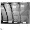
- insulation 1 in the form of a mat is located in the frame fields 2 between adjacent frames 3 of an aircraft (not shown in detail).
- the insulation is arranged between the cabin wall (not shown) and the invisible aircraft outer skin, with an invisible air gap being formed between the insulation 1 and the aircraft outer skin, which other components adjacent to the aircraft outer skin, such as the frames 3, also border on.
- a schematically illustrated duct network 4 consisting of several duct sections in the form of hoses serves to convey dry air from a lower region of the air gap to the upper region of the air gap.
- the duct network 4 has a plurality of first duct sections 5 which are guided through passages in the insulation 1 to the lower region of the air gap and have air inlet openings there (not shown).
- the duct network 4 also has second duct sections, which include a collecting duct 6 and a distribution duct 7.
- the first line sections 5 are connected to the collecting line 6 via multi-way valves (not shown), and the distribution line 7 is connected to several third line sections 8, which are each led through passages in the insulation 1 to the upper region of the air gap, where they have air outlet openings (not shown).
- An intermittently operated fan 9 has its inlet side connected to the collecting line 6 and its outlet side connected to the distribution line 7.
- the line network 4 is located largely in the space between the insulation 1 and the cabin wall.
- the fan 9 is also arranged there. Alternatively, however, it could also be arranged in a space above the cabin ceiling for reasons of space.
- each frame section 2 a first line section 5 and a third line section 8 are arranged.
- the arrangement of the first and third line sections 5, 8 with respect to the frame sections 2 can also be different, for example for reasons of space or for reasons of more effective air extraction or injection.
- fan 9 When fan 9 is switched on, it creates a pressure difference in the duct network 4, which causes dry air in the lower area of the air gap to be drawn into the inlet openings of the first duct sections 5 and moved via the collecting duct 6 and the distribution duct 7 to the third power sections 8, where it is blown back into the upper area of the air gap via their outlet openings.
- fan 9 instead of one fan 9, multiple fans can be used if necessary.
- the fan(s) are switched on and off depending on the temperature. For example, the fan(s) are switched on when the outside temperature during flight drops below approximately -7°C, approximately -9°C, or approximately -5°C.
- the condensation problem only occurs when the temperature of the outer skin falls below the dew point of the cabin air.
- the cabin air typically has a relative humidity of 10-15% at 23°C during flight. This corresponds to a dew point temperature of approximately -7°C.
- the air circulation system is only activated below this temperature.
- the control can be achieved with an on/off switch that activates the system with a fixed flow rate when the temperature falls below a certain threshold.
Landscapes
- Engineering & Computer Science (AREA)
- Aviation & Aerospace Engineering (AREA)
- Mechanical Engineering (AREA)
- Health & Medical Sciences (AREA)
- General Health & Medical Sciences (AREA)
- Pulmonology (AREA)
- Central Air Conditioning (AREA)
- Drying Of Solid Materials (AREA)
Description
Die Erfindung betrifft ein Verfahren zum Reduzieren von Kondensatausfall an inneren Oberflächen einer Flugzeugaußenhaut und benachbarten Bauteilen, wobei der Kondensatausfall durch Zufuhr von trockener Luft in einen oberen Bereich eines zwischen dem oberen Bereich und einem unteren Bereich sich erstreckenden Luftspaltes zwischen der Flugzeugaußenhaut und einer Dämmung, die zwischen einer Kabinenwand und der Flugzeugaußenhaut angeordnet ist. Die Erfindung betrifft auch eine Vorrichtung zur Durchführung dieses Verfahrens.The invention relates to a method for reducing condensate precipitation on the inner surfaces of an aircraft outer skin and adjacent components, wherein the condensate precipitation is reduced by supplying dry air into an upper region of an air gap extending between the upper region and a lower region between the aircraft outer skin and an insulation arranged between a cabin wall and the aircraft outer skin. The invention also relates to a device for carrying out this method.
Ein derartiges Verfahren und eine Vorrichtung zur Durchführung dieses Verfahrens sind aus der
Bei einem aus der
Ferner ist aus der
Die Aufgabe der Erfindung besteht darin, das eingangs beschriebene Verfahren zum Reduzieren von Kondensatausfall an inneren Oberflächen einer Flugzeugaußenhaut und benachbarten Bauteilen so zu gestalten, dass die Gewinnung der trockenen Luft, die in den oberen Bereich des zwischen dem oberen Bereich und einem unteren Bereich sich erstreckenden Luftspaltes zwischen der Flugzeugaußenhaut und einer Dämmung, die zwischen der Kabinenwand und der Flugzeugaußenhaut angeordnet ist, mit einem apparativ und energetisch geringeren Aufwand als bisher erfolgt, wobei das Verfahren nicht nur beim Bau neuer Flugzeuge sondern auch bei der Nachrüstung vorhandener Flugzeuge berücksichtigt werden kann. Auch soll eine Vorrichtung zur Durchführung dieses Verfahrens angegeben werden.The object of the invention is to design the method described above for reducing condensate precipitation on the inner surfaces of an aircraft outer skin and adjacent components in such a way that the extraction of dry air, which extends into the upper region of the air gap extending between the upper region and a lower region between the aircraft outer skin and an insulation arranged between the cabin wall and the aircraft outer skin, takes place with lower expenditure on equipment and energy than before, whereby the method can be taken into account not only in the construction of new aircraft but also in the retrofitting of existing aircraft. A device for carrying out this method should also be specified.
Die Aufgabe der Erfindung wird hinsichtlich des Verfahrens dadurch gelöst, dass gemäß dem kennzeichnenden Teil von Anspruch 1 die trockene Luft durch Absaugung aus dem unteren Bereich des Luftspaltes gewonnen wird und in einer oder mehreren Leitungen zum oberen Bereich des Luftspaltes geführt wird, wo sie in den Luftspalt wieder eintreten gelassen wird.The object of the invention is achieved with regard to the method in that, according to the characterizing part of claim 1, the dry air is obtained by suction from the lower region of the air gap and is guided in one or more lines to the upper region of the air gap, where it is allowed to enter the air gap again.
Hinsichtlich der Vorrichtung wird die Aufgabe der Erfindung dadurch gelöst, dass gemäß dem kennzeichnenden Teil des Anspruchs 6 die Leitung oder die Leitungen eine oder mehrere Eintrittsöffnungen am unteren Bereich des Luftspaltes hat bzw. haben, durch die hindurch trockene Luft im unteren Bereich des Luftspaltes absaugbar ist und dass die Leitung oder die Leitungen mit einem oder mehreren Lüftern verbunden ist bzw. sind, der oder die im Betrieb eine Druckdifferenz in der oder den Leitungen erzeugt bzw. erzeugen, welche die trockene Luft von der oder den Eintrittsöffnungen zu der oder den Austrittsöffnungen bewegt.With regard to the device, the object of the invention is achieved in that, according to the characterizing part of claim 6, the line or lines has or have one or more inlet openings at the lower region of the air gap, through which dry air in the lower region of the air gap can be sucked out, and in that the line or lines is or are connected to one or more fans which, during operation, generate or generate a pressure difference in the line or lines which moves the dry air from the inlet opening or openings to the outlet opening or openings.
Vorteilhafte Weiterbildungen des erfindungsgemäßen Verfahrens sind Gegenstand der Ansprüche 2 bis 7, und vorteilhafte Weiterbildungen der erfindungsgemäßen Vorrichtung sind Gegenstand der Ansprüche 8 bis 20.Advantageous further developments of the method according to the invention are the subject of
Der Erfindung liegt die Beobachtung zu Grunde, dass im Flug in den oberen Bereich des Luftspaltes warme und feuchte Luft aus der Kabine durch die nicht luftdichte Kabinenwand und die luftdurchlässige Dämmung hindurch einströmt, denn zwischen der Kabine und dem oberen Bereich des Luftspaltes herrscht ein Temperaturgradient, der zu einer thermisch induzierten Druckdifferenz führt, welche diese Luftströmung hervorruft. Typischerweise hat diese in den Luftspalt einströmende Luft eine Temperatur von etwa 20°C und eine relative Luftfeuchte RH von etwa 10%. Im Flug herrschen niedrige Außentemperaturen, die auch die Flugzeugaußenhaut und benachbarte Bauteile hinter der Dämmung kalt werden lassen. Die in den Luftspalt eingeströmte Luft kühlt sich ebenfalls ab. Da kalte Luft eine höhere Dichte hat, strömt diese hinter der Dämmung nach unten, wo sie wieder aus der Dämmung austreten würde, wenn sie erfindungsgemäß nicht abgesaugt werden würde. Die hinter der Dämmung nach unten strömende Luft ist trocken, da sie durch Kondensation an der kalten Flugzeugaußenhaut und den kalten benachbarten Bauteilen entfeuchtet wurde. Der Erfindungsgedanke besteht darin, diese Luft im unteren Bereich des Luftspaltes abzusaugen und oben insbesondere an zu schützenden Stellen wieder einzublasen, wodurch ein Umlauf trockener Luft entsteht. Der untere Bereich des Luftspaltes, wo die trockene Luft abgesaugt wird, stellt eine "kostenlose" oder zumindest "billige" Quelle trockener Luft dar.The invention is based on the observation that during flight, warm and humid air from the cabin flows into the upper area of the air gap through the non-airtight cabin wall and the air-permeable insulation. This is because there is a temperature gradient between the cabin and the upper area of the air gap, which leads to a thermally induced pressure difference, which causes this air flow. Typically, this air flowing into the air gap has a temperature of about 20°C and a Relative humidity (RH) of approximately 10%. During flight, low outside temperatures prevail, which also cool the aircraft's outer skin and neighboring components behind the insulation. The air flowing into the air gap also cools. Since cold air has a higher density, it flows downward behind the insulation, where it would escape from the insulation again if it were not extracted according to the invention. The air flowing downward behind the insulation is dry, having been dehumidified by condensation on the cold aircraft's outer skin and the cold neighboring components. The idea behind the invention is to extract this air from the lower area of the air gap and reinject it at the top, particularly at areas requiring protection, thus creating a circulation of dry air. The lower area of the air gap, where the dry air is extracted, represents a "free" or at least "cheap" source of dry air.
Ein Vorteil des erfindungsgemäßen Verfahrens besteht darin dass die Nutzung der Flugzeugaußenhaut als Entfeuchtungseinheit und das Absaugen hierdurch entfeuchteter Luft energieeffizienter ist als die bekannten Lösungen, bei denen die Luft aktiv entfeuchtet wird oder frische Zapfluft aus dem Triebwerk verwendet wird.An advantage of the method according to the invention is that the use of the aircraft outer skin as a dehumidification unit and the extraction of dehumidified air is more energy-efficient than the known solutions in which the air is actively dehumidified or fresh bleed air from the engine is used.
Die Verwendung eines oder mehrerer Lüfter in der erfindungsgemäßen Vorrichtung zur Durchführung des Verfahrens ist vorteilhaft, denn ein Lüfter benötigt typischerweise nur wenige Watt, während eine maschinelle Entfeuchtung aufgrund des Phasenwechsels und der bereits relativ trockenen Kabinenluft, die eine relative Feuchte von etwa 10% RH aufweist, mit hohem Aufwand verbunden ist. Auch Frischluft von außen, die eine Temperatur von etwa -50°C hat, ist eine "teure" Quelle für trockene Luft, da diese zunächst auf Kabinendruck komprimiert und anschließend konditioniert werden muss.The use of one or more fans in the device according to the invention for carrying out the method is advantageous because a fan typically requires only a few watts, whereas mechanical dehumidification is associated with considerable effort due to the phase change and the already relatively dry cabin air, which has a relative humidity of approximately 10% RH. Fresh air from outside, which has a temperature of approximately -50°C, is also an "expensive" source of dry air, as it must first be compressed to cabin pressure and then conditioned.
Durch die mit dem erfindungsgemäßen Verfahren bewirkte Reduzierung des Kondensatausfalls an der kalten Flugzeugaußenhaut und den benachbarten kalten Bauteilen, wird auch das Risiko der Bildung von Eis, das schmilzt, wenn die Flugzeugaußenhaut und die benachbarten Bauteile wieder warm werden, und zu Wasser wird, das unkontrolliert in die Kabine und auf die Passagiere abtropfen kann (Stichwort: "Rain in the plane"), reduziert.The reduction in condensate precipitation on the cold aircraft outer skin and the adjacent cold components achieved by the method according to the invention also reduces the risk of ice formation, which melts when the aircraft outer skin and the adjacent components become warm again and turns into water that can drip uncontrollably into the cabin and onto the passengers (keyword: "rain in the plane").
Ein Ausführungsbeispiel ist in der Zeichnung schematisch dargestellt und wird im Folgenden unter Bezugnahme auf diese Zeichnung näher beschrieben, wobei die Zeichnung eine Draufsicht auf einen Ausschnitt der Dämmung bei entfernter Kabinenwand von der Kabine aus zeigt.An embodiment is shown schematically in the drawing and is described in more detail below with reference to this drawing, wherein the drawing shows a plan view of a section of the insulation with the cabin wall removed from the cabin.
Wie die Zeichnung zeigt befindet sich eine Dämmung 1 in Form einer Matte in den Spantfeldern 2 zwischen benachbarten Spanten 3 eines nicht näher dargestellten Flugzeugs. Die Dämmung ist zwischen der nicht dargestellten Kabinenwand und der nicht sichtbaren Flugzeugaußenhaut angeordnet, wobei zwischen der Dämmung 1 und der Flugzeugaußenhaut ein nicht sichtbarer Luftspalt ausgebildet ist, an den auch noch andere zu der Flugzeugaußenhaut benachbarte Bauteile wie z.B. die Spanten 3 grenzen. Ein aus mehreren Leitungsabschnitten in Form von Schläuchen bestehendes, schematisch dargestelltes Leitungsnetz 4 dient zur Förderung von trockener Luft aus einem unteren Bereich des Luftspaltes in den oberen Bereich des Luftspaltes. Das Leitungsnetz 4 weist mehrere erste Leitungsabschnitte 5 auf, die durch Durchgänge in der Dämmung 1 hin zum unteren Bereich des Luftspaltes geführt sind und dort nicht dargestellte Lufteintrittsöffnungen aufweisen. Das Leitungsnetz 4 weist ferner zweite Leitungsabschnitte auf, zu denen eine Sammelleitung 6 und eine Verteilerleitung 7 gehören. Die ersten Leitungsabschnitte 5 sind über nicht dargestellte Mehrwegeventile mit der Sammelleitung 6 verbunden, und die Verteilerleitung 7 ist über nicht dargestellte Mehrwegeventile mit mehreren dritten Leitungsabschnitten 8 verbunden, die jeweils durch Durchgänge in der Dämmung 1 hin zum oberen Bereich des Luftspaltes geführt sind, wo sie nicht dargestellte Luftaustrittsöffnungen aufweisen. Ein intermittierend betreibbarer Lüfter 9 ist mit seiner Eintrittsseite an die Sammelleitung 6 angeschlossen und ist mit seiner Austrittsseite an die Verteilerleitung 7 angeschlossen. Das Leitungsnetz 4 befindet sich weitgehend im Raum zwischen der Dämmung 1 und der Kabinenwand. Auch der Lüfter 9 ist dort angeordnet. Alternativ könnte er aber auch aus Platzgründen in einem Raum oberhalb der Kabinendecke angeordnet werden. In jedem Spantfeld 2 ist jeweils ein erster Leitungsabschnitt 5 und jeweils ein dritter Leitungsabschnitt 8 angeordnet. Alternativ kann die Anordnung der ersten und dritten Leitungsabschnitte 5, 8 in Bezug auf die Spantfelder 2 beispielsweise aus Platzgründen oder aus Gründen einer effektiveren Luftabsaugung oder Einblasung auch anders getroffen werden.As the drawing shows, insulation 1 in the form of a mat is located in the
Wenn der Lüfter 9 eingeschaltet ist, erzeugt er im Leitungsnetz 4 eine Druckdifferenz, die dazu führt, dass trockene Luft im unteren Bereich des Luftspaltes in die Eintrittsöffnungen der ersten Leitungsabschnitte 5 eingesaugt und über die Sammelleitung 6 und die Verteilerleitung 7 zu den dritten Leistungsabschnitten 8 bewegt wird, wo sie über deren Austrittsöffnungen in den oberen Bereich des Luftspaltes wieder eingeblasen wird. Statt einem Lüfter 9 können auch bei Bedarf mehrere Lüfter eingesetzt werden.When
Der oder die Lüfter werden temperaturabhängig aus- und eingeschaltet. Zum Beispiel wird der oder werden die Lüfter eingeschaltet, wenn im Flug die Außentemperatur beispielsweise unter etwa -7°C oder etwa -9°C oder etwa -5°C sinkt.The fan(s) are switched on and off depending on the temperature. For example, the fan(s) are switched on when the outside temperature during flight drops below approximately -7°C, approximately -9°C, or approximately -5°C.
Bei Tests wurde festgestellt, dass der Leckagestrom hinter der Dämmebene, also vorbei an der kalten Flugzeugaußenhaut, etwa 0,7 bis 1,4 l/s pro Spantfeld beträgt. Um das Überströmen von warm-feuchter Kabinenluft hinter die Dämmebene zu verhindern, musste etwa diese Menge an alternativer Luft aufgebracht werden, wobei etwas mehr oder weniger je nach Dichtigkeit der Kabinenwand natürlich erforderlich ist.Tests have shown that the leakage flow behind the insulation layer, i.e. past the cold aircraft outer skin, is approximately 0.7 to 1.4 l/s per frame field. In order to prevent warm, humid cabin air from seeping behind the insulation layer, approximately this amount of alternative air had to be applied, although a little more or less is of course required depending on the tightness of the cabin wall.
Ferner wurde festgestellt, dass das Kondensationsproblem nur dann auftritt, wenn die Temperatur der Außenhaut unter den Taupunkt der Kabinenluft fällt. Die Luft in der Kabine hat typischerweise im Flug 10 - 15% relative Feuchte bei 23°C. Dies entspricht einer Taupunkttemperatur von etwa -7°C. Erst unter dieser Temperatur ist das Luftzirkulationssystem zu aktivieren. Im einfachsten Fall kann die Regelung mit einem Ein/Ausschalter vorgenommen werden, der ab dem Unterschreiten einer Grenztemperatur das System mit einem festen Volumenstrom aktiviert.It was further determined that the condensation problem only occurs when the temperature of the outer skin falls below the dew point of the cabin air. The cabin air typically has a relative humidity of 10-15% at 23°C during flight. This corresponds to a dew point temperature of approximately -7°C. The air circulation system is only activated below this temperature. In the simplest case, the control can be achieved with an on/off switch that activates the system with a fixed flow rate when the temperature falls below a certain threshold.
Selbstverständlich ist die Erfindung nicht auf die dargestellten Ausführungsformen beschränkt. Die vorstehende Beschreibung ist daher nicht als beschränkend, sondern als erläuternd anzusehen. Die nachfolgenden Ansprüche sind so zu verstehen, dass ein genanntes Merkmal in zumindest einer Ausführungsform der Erfindung vorhanden ist. Dies schließt die Anwesenheit weiterer Merkmale nicht aus. Sofern die Ansprüche und die vorstehende Beschreibung "erste" und "zweite" Ausführungsformen definieren, so dient diese Bezeichnung der Unterscheidung zweier gleichartiger Ausführungsformen, ohne eine Rangfolge festzulegen.Of course, the invention is not limited to the illustrated embodiments. The above description is therefore not to be considered limiting, but rather illustrative. The following claims are to be understood as meaning that a stated feature is present in at least one embodiment of the invention. This does not exclude the presence of further features. Where the claims and the above description define "first" and "second" embodiments, this designation serves to distinguish between two similar embodiments without establishing a priority.
Claims (15)
- Method for reducing condensate precipitate on inner surfaces of an outer skin of an aircraft, the condensate precipitate being reduced by supplying dry air into an upper region of an air gap, which extends between the upper region and a lower region, between the outer skin of an aircraft and an insulation (1), the insulation being arranged between a cabin wall and the outer skin of an aircraft, characterized in that the dry air is obtained by sucking it off from the lower region of the air gap and is conducted in one or more lines to the upper region of the air gap, where it re-enters the air gap.
- Method according to claim 1, characterized in that the dry air is sucked off at a plurality of outlet points of the lower region of the air gap that are spaced in the longitudinal direction of the aircraft and, at a plurality of inlet points of the upper region of the air gap that are spaced in the longitudinal direction of the aircraft, is allowed to reenter it, the dry air being guided between the outlet and inlet points through a network of lines (4) comprising the plurality of lines, in which network a pressure difference which moves the dry air from the outlet points to the inlet points is generated.
- Method according to claim 2, characterized in that a volumetric flow of dry air in the range between 0.7 I/s and 1.4 I/s is sucked out of the air gap at each outlet point and/or
in that a volumetric flow of dry air in the range between about 0.7 I/s and about 1.4 I/s enters the air gap at each inlet point. - Method according to any one of claims 1 to 3, characterized in that the dry air is sucked off from the lower region of the air gap and/or the dry air is supplied to the upper region of the air gap intermittently.
- Method according to any one of claims 1 to 4, characterized in that the dry air is only supplied to the upper region of the air gap at a predetermined outside temperature of the air surrounding the outer skin of the aircraft, or
in that the dry air is only supplied to the upper region of the air gap at an outside temperature of the air surrounding the outer skin of the aircraft of about 0°C or less or about -7°C or less. - Device for carrying out the method according to any one of claims 1 to 5, comprising one or more lines for supplying dry air through one or more outlet openings of the line or lines to an upper region of an air gap, which extends between the upper region and a lower region, between the outer skin of an aircraft and an insulation (1) arranged between a cabin wall and the outer skin of an aircraft, characterized in that the line or lines has or have one or more inlet openings at the lower region of the air gap, through which dry air can be sucked off in the lower region of the air gap, and in that the line or lines is or are connected to one or more fans (9) which, in operation, generates or generate a pressure difference in the line or lines, which moves the dry air from the inlet opening or openings to the outlet opening or openings.
- Device according to claim 6, characterized in that the fan or fans (9) is or are intermittently operable and/or
in that the fan or fans (9) is or are arranged in a space above an upper section of the cabin wall. - Device according to claim 6 or 7, characterized in that the inlet openings are located at first line sections (5) extending below the insulation (1) and/or in passages in the insulation (1) between the air gap and a space between the insulation and the cabin wall and are connected to second line sections arranged in the space between the insulation and the cabin wall and/or
in that each inlet opening and/or each outlet opening is or are respectively arranged in the region between two frames. - Device according to any one of claims 6 to 8, characterized in that the outlet openings are located at third line sections (8) which run above the insulation and/or in further passages in the insulation (1) between the space between the cabin wall and the insulation (1) and the air gap and are connected to the second line sections.
- Device according to claim 8 or 9, characterized in that the second line sections are connected to the first line sections (5) via first valves.
- Device according to claim 9 or 10, characterized in that the second line sections are connected to the third line sections (8) via second valves.
- Device according to any one of claims 8 to 11, characterized in that the fan or fans (9) are each connected to the second line sections on its or their inlet side and its or their outlet side.
- Device according to any one of claims 8 to 12, characterized in that the second line sections have a collection line (6) which is connected to the first line sections (5) and/or
in that the second line sections have a distribution line (7) which is connected to the third line sections (8). - Device according to claim 13, characterized in that the distribution line (7) is connected to the outlet side of a fan (9) and in that the collection line is connected to the inlet side of the fan (9).
- Device according to any one of claims 10 to 14, characterized in that the first valves and/or the second valves are each multiple-way valves.
Priority Applications (2)
| Application Number | Priority Date | Filing Date | Title |
|---|---|---|---|
| EP21216430.5A EP4201807B1 (en) | 2021-12-21 | 2021-12-21 | Method and apparatus for reducing condensate on inner surfaces of an aircraft outer skin and adjacent components |
| US18/068,658 US12312090B2 (en) | 2021-12-21 | 2022-12-20 | Reducing condensate precipitate on inner surfaces of an outer skin of an aircraft |
Applications Claiming Priority (1)
| Application Number | Priority Date | Filing Date | Title |
|---|---|---|---|
| EP21216430.5A EP4201807B1 (en) | 2021-12-21 | 2021-12-21 | Method and apparatus for reducing condensate on inner surfaces of an aircraft outer skin and adjacent components |
Publications (3)
| Publication Number | Publication Date |
|---|---|
| EP4201807A1 EP4201807A1 (en) | 2023-06-28 |
| EP4201807C0 EP4201807C0 (en) | 2025-06-04 |
| EP4201807B1 true EP4201807B1 (en) | 2025-06-04 |
Family
ID=78957645
Family Applications (1)
| Application Number | Title | Priority Date | Filing Date |
|---|---|---|---|
| EP21216430.5A Active EP4201807B1 (en) | 2021-12-21 | 2021-12-21 | Method and apparatus for reducing condensate on inner surfaces of an aircraft outer skin and adjacent components |
Country Status (2)
| Country | Link |
|---|---|
| US (1) | US12312090B2 (en) |
| EP (1) | EP4201807B1 (en) |
Family Cites Families (7)
| Publication number | Priority date | Publication date | Assignee | Title |
|---|---|---|---|---|
| SE465772B (en) | 1990-03-06 | 1991-10-28 | Ctt Systems Hb | PROCEDURE AND DEVICE TO PREVENT THE CONDUCT OF SCALE CONSTRUCTIONS |
| CA2256887C (en) | 1998-12-21 | 2008-07-08 | Indoor Air Technologies Inc. | Environment control system for aircraft having interior condensation problem reduction, cabin air quality improvement, fire suppression and fire venting functions |
| RU2466906C2 (en) * | 2007-02-23 | 2012-11-20 | Эйрбас Оперэйшнз Гмбх | Aircraft or spacecraft fuselage and method of active isolation of said fuselage |
| FR2971230B1 (en) * | 2011-02-09 | 2013-02-15 | Liebherr Aerospace Toulouse Sas | ANTI-CONDENSATION DEVICE AND METHOD FOR AN AIRCRAFT |
| US10745138B2 (en) * | 2018-03-23 | 2020-08-18 | The Boeing Company | Air drying system and method therefor |
| US11858641B2 (en) | 2019-10-24 | 2024-01-02 | The Boeing Company | Aircraft moisture control |
| US11591093B2 (en) * | 2020-04-29 | 2023-02-28 | The Boeing Company | Variable chiller exhaust with crown ventilation |
-
2021
- 2021-12-21 EP EP21216430.5A patent/EP4201807B1/en active Active
-
2022
- 2022-12-20 US US18/068,658 patent/US12312090B2/en active Active
Also Published As
| Publication number | Publication date |
|---|---|
| EP4201807C0 (en) | 2025-06-04 |
| US12312090B2 (en) | 2025-05-27 |
| US20230234711A1 (en) | 2023-07-27 |
| EP4201807A1 (en) | 2023-06-28 |
Similar Documents
| Publication | Publication Date | Title |
|---|---|---|
| DE102008025389B4 (en) | A method for insulating an aircraft cabin wall or for cooling or reheating aircraft cabin air and aircraft cabin wall suitable thereto | |
| DE602004003088T2 (en) | Cooling system | |
| DE102008029922B4 (en) | Air conditioning device | |
| DE2907310A1 (en) | PAINT SPRAY BOOTH | |
| DE69102997T2 (en) | METHOD AND MEANS FOR AVOIDING CONDENSATION IN SHELL HULL STRUCTURES. | |
| EP2318251B1 (en) | Rail vehicle switchable between winter and summer operation | |
| DE112010005583T5 (en) | Data Center Cooling | |
| DE60311559T2 (en) | air conditioning | |
| DE10350541A1 (en) | Air conditioning system and method for treating air for air conditioning of a room | |
| DE102008053814A1 (en) | Method and device for air treatment in wind power plants | |
| DE69829387T2 (en) | HIGHLY EFFICIENT AIR CONDITIONING AIR CONDITIONING | |
| WO2014012746A1 (en) | Cooling concept cold air shower | |
| EP4201807B1 (en) | Method and apparatus for reducing condensate on inner surfaces of an aircraft outer skin and adjacent components | |
| DE3018046A1 (en) | TEMPERATURE CONTROL SYSTEM | |
| DE102013109702A1 (en) | Air outlet and method of retrofitting | |
| EP4056940A1 (en) | Device and method for drying objects and/or materials, in particular wood | |
| EP3564127B1 (en) | Aircraft cooling system and aircraft having a vehicle cooling system | |
| DE1561642A1 (en) | Device for ventilation of paper machines | |
| EP2752318A1 (en) | Motor vehicle with a water tank | |
| DE602005000742T2 (en) | Ventilation system for the passenger compartment of a public transport | |
| EP3477212B1 (en) | Air distribution device and method for ventilating a room | |
| DE20008641U1 (en) | Device for air conditioning a room | |
| AT500559A1 (en) | ROOM TECHNOLOGY | |
| EP3370491B1 (en) | Assembly of a cooling system for cooling at least one server rack in a room | |
| DE69328491T2 (en) | AN ARRANGEMENT IN CONNECTION WITH A AIR CONDITIONER FOR LARGE ROOMS |
Legal Events
| Date | Code | Title | Description |
|---|---|---|---|
| PUAI | Public reference made under article 153(3) epc to a published international application that has entered the european phase |
Free format text: ORIGINAL CODE: 0009012 |
|
| STAA | Information on the status of an ep patent application or granted ep patent |
Free format text: STATUS: THE APPLICATION HAS BEEN PUBLISHED |
|
| AK | Designated contracting states |
Kind code of ref document: A1 Designated state(s): AL AT BE BG CH CY CZ DE DK EE ES FI FR GB GR HR HU IE IS IT LI LT LU LV MC MK MT NL NO PL PT RO RS SE SI SK SM TR |
|
| STAA | Information on the status of an ep patent application or granted ep patent |
Free format text: STATUS: REQUEST FOR EXAMINATION WAS MADE |
|
| 17P | Request for examination filed |
Effective date: 20231222 |
|
| RBV | Designated contracting states (corrected) |
Designated state(s): AL AT BE BG CH CY CZ DE DK EE ES FI FR GB GR HR HU IE IS IT LI LT LU LV MC MK MT NL NO PL PT RO RS SE SI SK SM TR |
|
| GRAP | Despatch of communication of intention to grant a patent |
Free format text: ORIGINAL CODE: EPIDOSNIGR1 |
|
| STAA | Information on the status of an ep patent application or granted ep patent |
Free format text: STATUS: GRANT OF PATENT IS INTENDED |
|
| INTG | Intention to grant announced |
Effective date: 20250211 |
|
| GRAS | Grant fee paid |
Free format text: ORIGINAL CODE: EPIDOSNIGR3 |
|
| GRAA | (expected) grant |
Free format text: ORIGINAL CODE: 0009210 |
|
| STAA | Information on the status of an ep patent application or granted ep patent |
Free format text: STATUS: THE PATENT HAS BEEN GRANTED |
|
| AK | Designated contracting states |
Kind code of ref document: B1 Designated state(s): AL AT BE BG CH CY CZ DE DK EE ES FI FR GB GR HR HU IE IS IT LI LT LU LV MC MK MT NL NO PL PT RO RS SE SI SK SM TR |
|
| REG | Reference to a national code |
Ref country code: GB Ref legal event code: FG4D Free format text: NOT ENGLISH |
|
| REG | Reference to a national code |
Ref country code: CH Ref legal event code: EP |
|
| REG | Reference to a national code |
Ref country code: DE Ref legal event code: R096 Ref document number: 502021007650 Country of ref document: DE |
|
| REG | Reference to a national code |
Ref country code: IE Ref legal event code: FG4D Free format text: LANGUAGE OF EP DOCUMENT: GERMAN |
|
| U01 | Request for unitary effect filed |
Effective date: 20250611 |
|
| U07 | Unitary effect registered |
Designated state(s): AT BE BG DE DK EE FI FR IT LT LU LV MT NL PT RO SE SI Effective date: 20250623 |
|
| PG25 | Lapsed in a contracting state [announced via postgrant information from national office to epo] |
Ref country code: ES Free format text: LAPSE BECAUSE OF FAILURE TO SUBMIT A TRANSLATION OF THE DESCRIPTION OR TO PAY THE FEE WITHIN THE PRESCRIBED TIME-LIMIT Effective date: 20250604 |
|
| PG25 | Lapsed in a contracting state [announced via postgrant information from national office to epo] |
Ref country code: GR Free format text: LAPSE BECAUSE OF FAILURE TO SUBMIT A TRANSLATION OF THE DESCRIPTION OR TO PAY THE FEE WITHIN THE PRESCRIBED TIME-LIMIT Effective date: 20250905 Ref country code: NO Free format text: LAPSE BECAUSE OF FAILURE TO SUBMIT A TRANSLATION OF THE DESCRIPTION OR TO PAY THE FEE WITHIN THE PRESCRIBED TIME-LIMIT Effective date: 20250904 |
|
| PG25 | Lapsed in a contracting state [announced via postgrant information from national office to epo] |
Ref country code: PL Free format text: LAPSE BECAUSE OF FAILURE TO SUBMIT A TRANSLATION OF THE DESCRIPTION OR TO PAY THE FEE WITHIN THE PRESCRIBED TIME-LIMIT Effective date: 20250604 |
|
| PG25 | Lapsed in a contracting state [announced via postgrant information from national office to epo] |
Ref country code: HR Free format text: LAPSE BECAUSE OF FAILURE TO SUBMIT A TRANSLATION OF THE DESCRIPTION OR TO PAY THE FEE WITHIN THE PRESCRIBED TIME-LIMIT Effective date: 20250604 |
|
| PG25 | Lapsed in a contracting state [announced via postgrant information from national office to epo] |
Ref country code: RS Free format text: LAPSE BECAUSE OF FAILURE TO SUBMIT A TRANSLATION OF THE DESCRIPTION OR TO PAY THE FEE WITHIN THE PRESCRIBED TIME-LIMIT Effective date: 20250904 |
|
| PG25 | Lapsed in a contracting state [announced via postgrant information from national office to epo] |
Ref country code: IS Free format text: LAPSE BECAUSE OF FAILURE TO SUBMIT A TRANSLATION OF THE DESCRIPTION OR TO PAY THE FEE WITHIN THE PRESCRIBED TIME-LIMIT Effective date: 20251004 |
|
| PG25 | Lapsed in a contracting state [announced via postgrant information from national office to epo] |
Ref country code: SM Free format text: LAPSE BECAUSE OF FAILURE TO SUBMIT A TRANSLATION OF THE DESCRIPTION OR TO PAY THE FEE WITHIN THE PRESCRIBED TIME-LIMIT Effective date: 20250604 |
|
| PG25 | Lapsed in a contracting state [announced via postgrant information from national office to epo] |
Ref country code: CZ Free format text: LAPSE BECAUSE OF FAILURE TO SUBMIT A TRANSLATION OF THE DESCRIPTION OR TO PAY THE FEE WITHIN THE PRESCRIBED TIME-LIMIT Effective date: 20250604 |
|
| PG25 | Lapsed in a contracting state [announced via postgrant information from national office to epo] |
Ref country code: SK Free format text: LAPSE BECAUSE OF FAILURE TO SUBMIT A TRANSLATION OF THE DESCRIPTION OR TO PAY THE FEE WITHIN THE PRESCRIBED TIME-LIMIT Effective date: 20250604 |
|
| U20 | Renewal fee for the european patent with unitary effect paid |
Year of fee payment: 5 Effective date: 20251222 |