EP4201751A1 - Elektronische steuereinrichtung - Google Patents
Elektronische steuereinrichtung Download PDFInfo
- Publication number
- EP4201751A1 EP4201751A1 EP21860864.4A EP21860864A EP4201751A1 EP 4201751 A1 EP4201751 A1 EP 4201751A1 EP 21860864 A EP21860864 A EP 21860864A EP 4201751 A1 EP4201751 A1 EP 4201751A1
- Authority
- EP
- European Patent Office
- Prior art keywords
- circuit
- controller
- diagnosis
- signal
- external
- Prior art date
- Legal status (The legal status is an assumption and is not a legal conclusion. Google has not performed a legal analysis and makes no representation as to the accuracy of the status listed.)
- Pending
Links
Images


Classifications
-
- B—PERFORMING OPERATIONS; TRANSPORTING
- B60—VEHICLES IN GENERAL
- B60L—PROPULSION OF ELECTRICALLY-PROPELLED VEHICLES; SUPPLYING ELECTRIC POWER FOR AUXILIARY EQUIPMENT OF ELECTRICALLY-PROPELLED VEHICLES; ELECTRODYNAMIC BRAKE SYSTEMS FOR VEHICLES IN GENERAL; MAGNETIC SUSPENSION OR LEVITATION FOR VEHICLES; MONITORING OPERATING VARIABLES OF ELECTRICALLY-PROPELLED VEHICLES; ELECTRIC SAFETY DEVICES FOR ELECTRICALLY-PROPELLED VEHICLES
- B60L3/00—Electric devices on electrically-propelled vehicles for safety purposes; Monitoring operating variables, e.g. speed, deceleration or energy consumption
- B60L3/0023—Detecting, eliminating, remedying or compensating for drive train abnormalities, e.g. failures within the drive train
- B60L3/0084—Detecting, eliminating, remedying or compensating for drive train abnormalities, e.g. failures within the drive train relating to control modules
-
- B—PERFORMING OPERATIONS; TRANSPORTING
- B60—VEHICLES IN GENERAL
- B60L—PROPULSION OF ELECTRICALLY-PROPELLED VEHICLES; SUPPLYING ELECTRIC POWER FOR AUXILIARY EQUIPMENT OF ELECTRICALLY-PROPELLED VEHICLES; ELECTRODYNAMIC BRAKE SYSTEMS FOR VEHICLES IN GENERAL; MAGNETIC SUSPENSION OR LEVITATION FOR VEHICLES; MONITORING OPERATING VARIABLES OF ELECTRICALLY-PROPELLED VEHICLES; ELECTRIC SAFETY DEVICES FOR ELECTRICALLY-PROPELLED VEHICLES
- B60L3/00—Electric devices on electrically-propelled vehicles for safety purposes; Monitoring operating variables, e.g. speed, deceleration or energy consumption
- B60L3/0007—Measures or means for preventing or attenuating collisions
-
- B—PERFORMING OPERATIONS; TRANSPORTING
- B60—VEHICLES IN GENERAL
- B60L—PROPULSION OF ELECTRICALLY-PROPELLED VEHICLES; SUPPLYING ELECTRIC POWER FOR AUXILIARY EQUIPMENT OF ELECTRICALLY-PROPELLED VEHICLES; ELECTRODYNAMIC BRAKE SYSTEMS FOR VEHICLES IN GENERAL; MAGNETIC SUSPENSION OR LEVITATION FOR VEHICLES; MONITORING OPERATING VARIABLES OF ELECTRICALLY-PROPELLED VEHICLES; ELECTRIC SAFETY DEVICES FOR ELECTRICALLY-PROPELLED VEHICLES
- B60L3/00—Electric devices on electrically-propelled vehicles for safety purposes; Monitoring operating variables, e.g. speed, deceleration or energy consumption
- B60L3/0023—Detecting, eliminating, remedying or compensating for drive train abnormalities, e.g. failures within the drive train
- B60L3/0046—Detecting, eliminating, remedying or compensating for drive train abnormalities, e.g. failures within the drive train relating to electric energy storage systems, e.g. batteries or capacitors
-
- B—PERFORMING OPERATIONS; TRANSPORTING
- B60—VEHICLES IN GENERAL
- B60L—PROPULSION OF ELECTRICALLY-PROPELLED VEHICLES; SUPPLYING ELECTRIC POWER FOR AUXILIARY EQUIPMENT OF ELECTRICALLY-PROPELLED VEHICLES; ELECTRODYNAMIC BRAKE SYSTEMS FOR VEHICLES IN GENERAL; MAGNETIC SUSPENSION OR LEVITATION FOR VEHICLES; MONITORING OPERATING VARIABLES OF ELECTRICALLY-PROPELLED VEHICLES; ELECTRIC SAFETY DEVICES FOR ELECTRICALLY-PROPELLED VEHICLES
- B60L3/00—Electric devices on electrically-propelled vehicles for safety purposes; Monitoring operating variables, e.g. speed, deceleration or energy consumption
- B60L3/04—Cutting off the power supply under fault conditions
Definitions
- the present invention relates to a configuration of an in-vehicle electronic control unit, and particularly to a technique effective for application to an electronic control unit mounted on an electrically driven vehicle such as a hybrid electric vehicle or an electric vehicle.
- a high voltage power supply of about 400 V is supplied from a lithium ion battery to an inverter in order to operate a motor.
- a high-voltage power supply line comes into contact with a body of a vehicle at the time of collision or the like, there is a risk of an electric shock due to touching to the vehicle.
- a relay is used between the lithium ion battery and a load to perform control to shut off the high-voltage power supply line except during vehicle operation.
- PTL 1 discloses "a power supply breaker mounted on a vehicle, the power supply breaker including: a power supply circuit having a battery, a load, and a relay; a relay control part that controls the relay to bring the battery and the load into and out of contact with each other; and a breaking mechanism that breaks a signal line provided between the relay control part and the relay to separate the battery and the load from each other at the time of vehicle collision".
- the relay is used between the lithium ion battery and the load.
- an ON failure occurs in which the relay is stuck in an ON state and cannot be turned OFF because of a short circuit or the like between an output circuit controlling the relay and a peripheral circuit.
- PTL 1 discloses a technique for forcibly shutting off the relay by cutting the high-voltage power supply line with a cutting blade when the vehicle collides.
- an object of the present invention is to provide an electronic control unit mounted on an electrically driven vehicle, the electronic control unit being excellent in reliability and convenience in which recovery is easy while reliably shutting off a high-voltage power supply line at the time of collision of a vehicle or failure of a power supply shutoff circuit.
- the present invention is characterized by including: an external load switching element that drives an external load; a controller that drives the external load switching element; a shutoff transistor that shuts off connection between an internal GND and an external GND or connection between an internal power supply system and an external power supply system; a diagnosis circuit that receives, as input, a diagnosis signal of a control circuit that controls the external load by the external load switching element, and a diagnosis signal of the controller, and outputs a diagnosis result; and an output holding circuit that holds an output signal of the diagnosis circuit, wherein the shutoff transistor shuts off the connection between the internal GND and the external GND or the connection between the internal power supply system and the external power supply system on the basis of the signal held by the output holding circuit.
- an electronic control unit mounted on an electrically driven vehicle, the electronic control unit being excellent in reliability and convenience in which recovery is easy while reliably shutting off a high-voltage power supply line at the time of collision of a vehicle or failure of a power supply shutoff circuit.
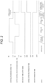
- FIG. 1 is a schematic configuration diagram of the electronic control unit of the present embodiment.
- an electronic control unit (ECU) 100 of the present embodiment includes an external load switching element 103 for driving an external load 101, and a controller 102 such as a microcontroller for driving the external load switching element 103.
- a controller diagnosis signal 114 from the controller 102 is input to a NOR circuit 106 via filters such as a filter capacitor 104 and a filter resistor 105 so as to be HI at the normal time.
- an output control circuit diagnosis signal 115 is input to the NOR circuit 106 as a signal that becomes LO when the external load 101 is turned ON.
- the electronic control unit (ECU) 100 includes an output holding circuit 107 that holds output from the NOR circuit 106, and includes a charge extracting transistor 108 that extracts a gate charge of a shutoff transistor 109.
- the shutoff transistor 109 has a function of shutting off an external GND (vehicle GND) 111 of a vehicle or the like and an ECU internal GND (ECU GND) 112.
- While the GND inside the electronic control unit (ECU) 100 can control influence at the time of shutoff of the GND, depending on which of the vehicle GND 111 and the ECU GND 112 is set as the GND, a GND of the output holding circuit 107 and a GND of the charge extracting transistor 108 are common to the external GND (vehicle GND) 111 in order to maintain a shutoff state after the shutoff.
- ECU electronice control unit
- the controller diagnosis signal 114 is output as LO until the controller 102 such as the microcontroller is activated.
- the output control circuit diagnosis signal 115 is pulled up with a battery voltage VBAT 110, a HI output is maintained.
- the NOR circuit 106 outputs LO and the output holding circuit 107 also outputs LO, the charge extracting transistor 108 is put into an OFF state.
- the ECU internal GND 112 is connected to the external GND 111 of the vehicle or the like.
- the controller 102 After the activation of the controller 102, in a normal state, the controller 102 outputs the controller diagnosis signal 114 as HI. Since the NOR circuit 106 maintains the LO output, the shutoff transistor 109 maintains ON, and the ECU internal GND 112 maintains the connection with the external GND 111 of the vehicle or the like.
- the controller (microcontroller) 102 turns the external load 101 ON, the output control circuit signal 115 is output as LO. Since the controller diagnosis signal 114 is HI and the NOR circuit 106 maintains the LO output, the shutoff transistor 109 maintains ON, and the ECU internal GND 112 maintains the connection with the external GND 111 of the vehicle or the like.
- the controller diagnosis signal 114 becomes LO due to a failure of an internal circuit of the electronic control unit (ECU) 100, an external signal (collision signal) 113 from the outside, or the like, when the output control circuit diagnosis signal 115 is HI and the external load 101 is OFF, the NOR circuit 106 maintains the LO output, so that the shutoff transistor 109 maintains ON, and the ECU internal GND 112 maintains the connection with the external GND 111 of the vehicle or the like.
- the controller diagnosis signal 114 is LO due to a failure of an internal circuit of the electronic control unit (ECU) 100, the external signal (collision signal) 113 from the outside, or the like, and when the external load 101 has an ON failure, the output control circuit diagnosis signal 115 becomes LO, and thus, the NOR circuit 106 becomes HI.
- the charge extracting transistor 108 is turned ON upon reception of the HI output of the output holding circuit 107, and extracts a gate voltage of the shutoff transistor 109. Since the shutoff transistor 109 is turned OFF, the connection between the ECU internal GND 112 and the external GND 111 of the vehicle or the like is shut off.
- the ECU internal GND 112 is shut off from the external GND 111 of the vehicle or the like, by which a path in which a current flows to the external GND 111 of the vehicle or the like through the external load switching element 103 is shut off in the external load 101, so that the external load 101 is shut off.
- controller diagnosis signal 114 can be used not only for a failure of an internal circuit or the like but also for preventing an ON failure of the external load 101 by outputting the controller diagnosis signal 114 as an LO output upon receiving a signal from an ECU different from the electronic control unit (ECU) 100.
- shutoff of the shutoff transistor 109 that shuts off the ECU internal GND 112 and the external GND 111 of the vehicle or the like is held by the output holding circuit 107, the holding of the output holding circuit 107 is released by once turning OFF and again turning ON the battery voltage VBAT 110 supplied to the electronic control unit (ECU) 100, so that the external load 101 can be turned ON again.
- the electronic control unit (ECU) 100 of the present embodiment includes the external load switching element 103 that drives the external load 101, the controller 102 that drives the external load switching element 103, the shutoff transistor 109 that shuts off the connection between the ECU internal GND 112 and the external GND 111 of the vehicle or the like, the diagnosis circuit (NOR circuit 106) that receives, as input, the diagnosis signal (output control circuit diagnosis signal 115) of the control circuit that controls the external load 101 by the external load switching element 103, and the diagnosis signal (controller diagnosis signal 114) of the controller 102 and outputs the diagnosis result, and the output holding circuit 107 that holds the output signal of the diagnosis circuit (NOR circuit 106), and the shutoff transistor 109 shuts off the connection between the ECU internal GND 112 and the external GND 111 of the vehicle or the like on the basis of the signal held by the output holding circuit 107.
- an ON failure of the external load 101 is detected on the basis of the diagnosis signal (output control circuit diagnosis signal 115) of the control circuit that controls the external load 101 by the external load switching element 103, and the diagnosis signal (controller diagnosis signal 114) of the controller 102.
- the external load 101 is a relay that controls a high-voltage power supply line
- FIG. 3 is a schematic configuration diagram of the electronic control unit of the present embodiment.
- ECU electronice control unit
- FIG. 3 is a schematic configuration diagram of the electronic control unit of the present embodiment.
- a filter circuit 120 using filter capacitors 104, 118, filter resistors 105, 117, a filter diode 116, and the like is added for the controller diagnosis signal 114.
- Other configurations are similar to those of the first embodiment ( FIG. 1 ).
- An object of the filter circuit 120 is to exclude a DC component by the filter capacitor 118.
- PWM output is input as an input of the filter circuit 120
- a voltage is divided by the filter capacitor 118 and other circuits at the time of HI input of PWM, and charges are accumulated in the filter capacitor 104.
- charges of the filter capacitor 118 are discharged through the filter resistor 117. Since the charges of the filter capacitor 104 are limited to the filter diode 116, no charge is discharged from the filter resistor 117.
- Filter output becomes HI output by repetition of HI and LO.
- a controller output signal 119 performs the PWM output in a normal state.
- the controller diagnosis signal 114 becomes HI through the filter circuit 120.
- the filter circuit 120 causes the controller diagnosis signal 114 to be LO.
- the controller diagnosis signal 114 becomes LO according to the configuration of the present embodiment. Therefore, when the external load 101 has an ON failure, it is possible to shut off the signal.
- the electronic control unit (ECU) 100 of the present embodiment includes the filter circuit 120 configured of the filter capacitors 104, 118, the filter resistors 105, 117, and the filter diode 116, and the filter circuit 120 is connected between the controller 102 and the diagnosis circuit (NOR circuit 106).
- the PWM output from the controller 102 is transmitted via the filter circuit 120 to exclude the DC component output from the controller 102, and is input to the diagnosis circuit (NOR circuit 106) as the diagnosis signal (controller diagnosis signal 114) of the controller 102.
- FIG. 4 is a schematic configuration diagram of the electronic control unit according to the present embodiment.
- the filter circuit 120 is added between the controller 102 such as a microcontroller and the external load switching element 103.
- controller 102 such as a microcontroller
- Other configurations are similar to those of the first embodiment ( FIG. 1 ).
- the electronic control unit (ECU) 100 of the present embodiment includes the filter circuit 120 configured of the filter capacitors 104, 118, the filter resistors 105, 117, and the filter diode 116, and the filter circuit 120 is connected between the controller 102 and the external load switching element 103.
- a gate voltage of the external load switching element 103 becomes HI, the external load switching element 103 is turned ON, and the external load 101 can be turned ON.
- the controller output signal 119 is fixed to the HI output due to a failure of an internal circuit of the electronic control unit (ECU) 100 or the like, the external load switching element 103 is not turned ON, so that it is possible to prevent the external load 101 from having an ON failure.
- the controller 102 does not control the external load switching element 103, the output of the controller diagnosis signal 114 becomes LO. Therefore, when the external load 101 has an ON failure and the output control circuit diagnosis signal 115 becomes LO, the shutoff transistor 109 is turned OFF, so that the current path of the external load 101 is shut off, and the ON failure of the external load 101 can be prevented.
- FIG. 5 is a schematic configuration diagram of the electronic control unit according to the present embodiment.
- an electronic control unit (ECU) 100 of the present embodiment directly inputs the controller diagnosis signal 114 from an external signal of the electronic control unit (ECU) 100 instead of the output from the controller 102.
- controller diagnosis signal 114 may be configured to be input to the NOR circuit 106 via the filter circuit 120 as in the second embodiment ( FIG. 3 ).
- the electronic control unit (ECU) 100 of the present embodiment uses the external signal 113 (for example, vehicle collision signal) input from the outside as the diagnosis signal (controller diagnosis signal 114) of the controller 102.
- the external signal 113 for example, vehicle collision signal
- controller diagnosis signal 114 the diagnosis signal of the controller 102.
- An external controller (not illustrated) of the electronic control unit (ECU) 100 can forcibly turn OFF an ON state of the external load 101.
- FIG. 6 is a schematic configuration diagram of the electronic control unit according to the present embodiment.
- an electronic control unit (ECU) 100 of the present embodiment is a system for controlling the external load 101 by supplying an ECU power supply VB 121 of the electronic control unit (ECU) 100 to the external load 101.
- the output control circuit diagnosis signal 115 becomes LO by a NOT circuit 122.
- the control circuit diagnosis signal 114 is LO, the NOR circuit 106 is HI.
- controller diagnosis signal 114 may be configured to use the external signal 113 as in the fourth embodiment.
- the shutoff transistor 109 Since HI input of the NOR circuit 106 is held by the output holding circuit 107, the shutoff transistor 109 is turned OFF, so that the connection between the battery voltage VBAT 110 and the ECU power supply VB 121 is shut off. Since the output of the external load 101 is shut off by shutting off the power supply of the ECU power supply VB 121, the external load 101 is shut off.
- the diagnosis circuit is the NOT circuit 122 and the NOR circuit 106
- the diagnosis signal (output control circuit diagnosis signal 115) of the control circuit that controls the external load 101 to an internal power supply voltage (ECU power supply VB 121) by the external load switching element 103 is input to the NOR circuit 106 via the NOT circuit 122
- the diagnosis signal (controller diagnosis signal 114) of the controller 102 is input to the NOR circuit 106
- the connection between the internal power supply system (ECU power supply VB 121) and the external power supply system (battery voltage VBAT 110) is shut off by the shutoff transistor 109 on the basis of the output signal of the NOR circuit 106 held by the output holding circuit 107.
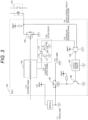
- FIG. 7 is a schematic configuration diagram of the electronic control unit according to the present embodiment.
- ECU electronice control unit
- the filter circuit 120 using the filter capacitors 104, 118, the filter resistors 105, 117, the filter diode 116, and the like is added for the controller diagnosis signal 114.
- Other configurations are similar to those of the fifth embodiment ( FIG. 6 ).
- the electronic control unit (ECU) 100 of the present embodiment includes the filter circuit 120 configured of filter capacitors 104, 118, filter resistors 105,117, and the filter diode 116, and PWM output from the controller 102 is transmitted via the filter circuit 120 to exclude a DC component output from the controller 102, and is input to the NOR circuit 106 as the diagnosis signal (controller diagnosis signal 114) of the controller 102.
- the filter circuit 120 configured of filter capacitors 104, 118, filter resistors 105,117, and the filter diode 116
- PWM output from the controller 102 is transmitted via the filter circuit 120 to exclude a DC component output from the controller 102, and is input to the NOR circuit 106 as the diagnosis signal (controller diagnosis signal 114) of the controller 102.
- the controller diagnosis signal 114 becomes LO according to the method of the present embodiment. Therefore, when the external load 101 has an ON failure, it is possible to shutoff the signal.
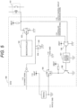
- FIG. 8 is a schematic configuration diagram of the electronic control unit according to the present embodiment.
- the filter circuit 120 is added between the controller 102 such as a microcontroller and the external load switching element 103.
- an AND circuit 123 is connected instead of the NOR circuit 106 and the NOT circuit 122 of the fifth embodiment ( FIG. 6 ).
- Other configurations are similar to those of the fifth embodiment ( FIG. 6 ).
- the electronic control unit (ECU) 100 of the present embodiment includes the filter circuit 120 configured of the filter capacitors 104, 118, the filter resistors 105, 117, and the filter diode 116.
- the filter circuit 120 is connected between the controller 102 and the external load switching element 103.
- the diagnosis circuit is the AND circuit 123.
- the PWM output from the controller 102 is transmitted via the filter circuit 120 to exclude a DC component output from the controller 102, and is input to the AND circuit 123 as the diagnosis signal (controller diagnosis signal 114) of the controller 102.
- the shutoff transistor 109 shuts off connection between the internal power supply system (ECU power supply VB 121) and the external power supply system (battery voltage VBAT 110) on the basis of an output signal of the AND circuit 123 held by the output holding circuit 107.
- the gate voltage of the external load switching element 103 becomes LO, the external load switching element 103 is turned ON, and the external load 101 can be turned ON.
- the controller output signal 119 is fixed to the LO output or the HI output due to a failure of an internal circuit of the electronic control unit (ECU) 100 or the like, the external load switching element 103 is not turned ON, so that it is possible to prevent the external load 101 from having an ON failure.
- the controller 102 does not control the external load switching element 103, the output of the controller diagnosis signal 114 becomes LO. Therefore, when the external load 101 has an ON failure and the output control circuit diagnosis signal 115 becomes HI, the AND circuit 123 performs HI output, the output holding circuit 107 holds the HI output, and the shutoff transistor 109 is turned OFF, so that the current path of the external load 101 is shut off, and the ON failure of the external load 101 can be prevented.
- diagnosis circuit (the NOR circuit 106, the NOT circuit 122, the AND circuit 123) and the output holding circuit 107 described in each of the above embodiments, it is desirable to use a semiconductor element in which at least these circuits are formed on the same semiconductor chip.
- diagnosis circuit and the output holding circuit 107 By forming the diagnosis circuit and the output holding circuit 107 on the same semiconductor chip, wiring delay between both the circuits is eliminated, and the shutoff transistor 109 can be operated without delay.
- the present invention is not limited to the above-described embodiments, but includes various modifications.
- the above-described embodiments have been described in detail in order to facilitate understanding of the present invention, and are not necessarily limited to those including all the described configurations.
- a part of the configuration of one embodiment can be replaced with a configuration of another embodiment, and the configuration of one embodiment can be added to a configuration of another embodiment.
- addition, deletion, or replacement of another configuration can be made.
Landscapes
- Engineering & Computer Science (AREA)
- Power Engineering (AREA)
- Life Sciences & Earth Sciences (AREA)
- Sustainable Development (AREA)
- Sustainable Energy (AREA)
- Transportation (AREA)
- Mechanical Engineering (AREA)
- Electronic Switches (AREA)
Applications Claiming Priority (2)
| Application Number | Priority Date | Filing Date | Title |
|---|---|---|---|
| JP2020140687 | 2020-08-24 | ||
| PCT/JP2021/017531 WO2022044432A1 (ja) | 2020-08-24 | 2021-05-07 | 電子制御装置 |
Publications (2)
| Publication Number | Publication Date |
|---|---|
| EP4201751A1 true EP4201751A1 (de) | 2023-06-28 |
| EP4201751A4 EP4201751A4 (de) | 2025-01-01 |
Family
ID=80353001
Family Applications (1)
| Application Number | Title | Priority Date | Filing Date |
|---|---|---|---|
| EP21860864.4A Pending EP4201751A4 (de) | 2020-08-24 | 2021-05-07 | Elektronische steuereinrichtung |
Country Status (5)
| Country | Link |
|---|---|
| US (1) | US12502972B2 (de) |
| EP (1) | EP4201751A4 (de) |
| JP (1) | JP7492588B2 (de) |
| CN (1) | CN115943093B (de) |
| WO (1) | WO2022044432A1 (de) |
Family Cites Families (18)
| Publication number | Priority date | Publication date | Assignee | Title |
|---|---|---|---|---|
| JPS5636093B2 (de) * | 1973-03-16 | 1981-08-21 | ||
| US5389824A (en) * | 1992-03-17 | 1995-02-14 | Kabushiki Kaisha Equos Research | Power supply cut off apparatus |
| US5488283A (en) * | 1993-09-28 | 1996-01-30 | Globe-Union, Inc. | Vehicle battery system providing battery back-up and opportunity charging |
| JP4285827B2 (ja) | 1999-02-25 | 2009-06-24 | 三菱電機株式会社 | エレベーターのブレーキ制御装置 |
| JP2004159439A (ja) * | 2002-11-07 | 2004-06-03 | Toyota Motor Corp | 電源遮断装置 |
| JP4595482B2 (ja) * | 2004-10-08 | 2010-12-08 | トヨタ自動車株式会社 | 車両用電源装置 |
| JP4573884B2 (ja) * | 2008-06-18 | 2010-11-04 | 三菱電機株式会社 | 車載電子制御装置の電源異常検出回路 |
| JP5960966B2 (ja) * | 2011-10-21 | 2016-08-02 | 株式会社ケーヒン | 電子制御装置 |
| EP2607178B1 (de) * | 2011-12-21 | 2014-07-30 | Volvo Car Corporation | Stromversorgung zum Versorgen einer elektrischen Last eines Fahrzeugs |
| KR20130127214A (ko) * | 2012-05-14 | 2013-11-22 | 엘에스산전 주식회사 | 모터 제어 장치 및 이의 모터 구동 제어 방법 |
| JP6267232B2 (ja) | 2013-11-29 | 2018-01-24 | 日立オートモティブシステムズ株式会社 | 負荷駆動回路 |
| KR101535011B1 (ko) * | 2014-02-18 | 2015-07-07 | 현대자동차주식회사 | 차량용 배터리 전원 차단 장치 및 방법 |
| JP6751905B2 (ja) * | 2015-09-11 | 2020-09-09 | パナソニックIpマネジメント株式会社 | 照明制御装置、照明装置、および移動体 |
| JP2017114373A (ja) | 2015-12-25 | 2017-06-29 | 矢崎総業株式会社 | ジャンクションボックス |
| FR3055466B1 (fr) * | 2016-08-29 | 2018-09-21 | Schneider Electric Industries Sas | Unite de controle d'un disjoncteur comportant un systeme de gestion d'alimentation electrique et disjoncteur comportant une telle unite |
| JP6695244B2 (ja) | 2016-09-14 | 2020-05-20 | 日立オートモティブシステムズ株式会社 | 電源制御装置 |
| JP6496342B2 (ja) * | 2017-03-28 | 2019-04-03 | 株式会社Subaru | 車両用制御装置 |
| US11418042B2 (en) * | 2018-02-15 | 2022-08-16 | Hitachi Astemo, Ltd. | Battery management unit |
-
2021
- 2021-05-07 JP JP2022545306A patent/JP7492588B2/ja active Active
- 2021-05-07 WO PCT/JP2021/017531 patent/WO2022044432A1/ja not_active Ceased
- 2021-05-07 EP EP21860864.4A patent/EP4201751A4/de active Pending
- 2021-05-07 US US18/022,714 patent/US12502972B2/en active Active
- 2021-05-07 CN CN202180051590.9A patent/CN115943093B/zh active Active
Also Published As
| Publication number | Publication date |
|---|---|
| JPWO2022044432A1 (de) | 2022-03-03 |
| US12502972B2 (en) | 2025-12-23 |
| CN115943093A (zh) | 2023-04-07 |
| JP7492588B2 (ja) | 2024-05-29 |
| US20240034151A1 (en) | 2024-02-01 |
| EP4201751A4 (de) | 2025-01-01 |
| WO2022044432A1 (ja) | 2022-03-03 |
| CN115943093B (zh) | 2026-01-02 |
Similar Documents
| Publication | Publication Date | Title |
|---|---|---|
| JP6719015B2 (ja) | 過電流保護回路 | |
| JP3117262B2 (ja) | 過電圧保護装置 | |
| US6731023B2 (en) | Backup power supply for restraint control module | |
| DE102011005729B4 (de) | Fahrzeugenergiesystem | |
| KR101704112B1 (ko) | 모터 구동 장치 | |
| US11059439B2 (en) | In-vehicle power supply device | |
| JPH07228215A (ja) | 車両用安全装置の制御回路 | |
| CN114448079A (zh) | 电源切换控制系统 | |
| CN110023131B (zh) | 具有电机的机动车、尤其是混合动力车辆或电动车辆 | |
| US10882475B2 (en) | Multi-voltage control device for a motor vehicle, motor vehicle and operating method for the control device | |
| CN1926010B (zh) | 借助于能量储备器的点火电流给至少一个点火级电流馈电的装置 | |
| US20130062936A1 (en) | Load control device | |
| CN107431348A (zh) | 被保护免受过压的电子控制设备 | |
| US12502972B2 (en) | Electronic control unit | |
| JP7492586B2 (ja) | 車載用電子制御装置及び車載機器制御方法 | |
| EP3839539A1 (de) | Verfahren, system und vorrichtung zur diagnose einer fehlfunktion in einer stromverteilungseinheit | |
| US20050264972A1 (en) | Relay control device for a direct current electrical apparatus | |
| US20200384890A1 (en) | Electronic control device | |
| CN119010544A (zh) | 主动放电电路和电力转换装置 | |
| US10826486B2 (en) | Switching driving circuit, switching circuit, and power supply device | |
| CN113785491A (zh) | 控制装置 | |
| CN114559817B (zh) | 一种车辆控制方法、控制器及车辆 | |
| JP6894957B2 (ja) | 誤出力防止回路 | |
| JP2009196541A (ja) | エアバッグ点火回路及びエアバッグ点火ユニット | |
| JP2001206190A (ja) | 乗員保護装置 |
Legal Events
| Date | Code | Title | Description |
|---|---|---|---|
| STAA | Information on the status of an ep patent application or granted ep patent |
Free format text: STATUS: THE INTERNATIONAL PUBLICATION HAS BEEN MADE |
|
| PUAI | Public reference made under article 153(3) epc to a published international application that has entered the european phase |
Free format text: ORIGINAL CODE: 0009012 |
|
| STAA | Information on the status of an ep patent application or granted ep patent |
Free format text: STATUS: REQUEST FOR EXAMINATION WAS MADE |
|
| 17P | Request for examination filed |
Effective date: 20230324 |
|
| AK | Designated contracting states |
Kind code of ref document: A1 Designated state(s): AL AT BE BG CH CY CZ DE DK EE ES FI FR GB GR HR HU IE IS IT LI LT LU LV MC MK MT NL NO PL PT RO RS SE SI SK SM TR |
|
| DAV | Request for validation of the european patent (deleted) | ||
| DAX | Request for extension of the european patent (deleted) | ||
| A4 | Supplementary search report drawn up and despatched |
Effective date: 20241128 |
|
| RIC1 | Information provided on ipc code assigned before grant |
Ipc: B60L 3/00 20190101ALI20241122BHEP Ipc: B60L 3/04 20060101ALI20241122BHEP Ipc: B60R 16/02 20060101AFI20241122BHEP |
|
| RAP3 | Party data changed (applicant data changed or rights of an application transferred) |
Owner name: ASTEMO, LTD. |