EP4201544B1 - Workpiece conveying wheeled platform and working system - Google Patents
Workpiece conveying wheeled platform and working system Download PDFInfo
- Publication number
- EP4201544B1 EP4201544B1 EP21858243.5A EP21858243A EP4201544B1 EP 4201544 B1 EP4201544 B1 EP 4201544B1 EP 21858243 A EP21858243 A EP 21858243A EP 4201544 B1 EP4201544 B1 EP 4201544B1
- Authority
- EP
- European Patent Office
- Prior art keywords
- slider
- placing part
- workpiece
- pallet
- wheeled platform
- Prior art date
- Legal status (The legal status is an assumption and is not a legal conclusion. Google has not performed a legal analysis and makes no representation as to the accuracy of the status listed.)
- Active
Links
Images




Classifications
-
- B—PERFORMING OPERATIONS; TRANSPORTING
- B65—CONVEYING; PACKING; STORING; HANDLING THIN OR FILAMENTARY MATERIAL
- B65G—TRANSPORT OR STORAGE DEVICES, e.g. CONVEYORS FOR LOADING OR TIPPING, SHOP CONVEYOR SYSTEMS OR PNEUMATIC TUBE CONVEYORS
- B65G65/00—Loading or unloading
-
- B—PERFORMING OPERATIONS; TRANSPORTING
- B23—MACHINE TOOLS; METAL-WORKING NOT OTHERWISE PROVIDED FOR
- B23Q—DETAILS, COMPONENTS, OR ACCESSORIES FOR MACHINE TOOLS, e.g. ARRANGEMENTS FOR COPYING OR CONTROLLING; MACHINE TOOLS IN GENERAL CHARACTERISED BY THE CONSTRUCTION OF PARTICULAR DETAILS OR COMPONENTS; COMBINATIONS OR ASSOCIATIONS OF METAL-WORKING MACHINES, NOT DIRECTED TO A PARTICULAR RESULT
- B23Q7/00—Arrangements for handling work specially combined with or arranged in, or specially adapted for use in connection with, machine tools, e.g. for conveying, loading, positioning, discharging, sorting
- B23Q7/16—Loading work on to conveyors; Arranging work on conveyors, e.g. varying spacing between individual workpieces
-
- B—PERFORMING OPERATIONS; TRANSPORTING
- B21—MECHANICAL METAL-WORKING WITHOUT ESSENTIALLY REMOVING MATERIAL; PUNCHING METAL
- B21D—WORKING OR PROCESSING OF SHEET METAL OR METAL TUBES, RODS OR PROFILES WITHOUT ESSENTIALLY REMOVING MATERIAL; PUNCHING METAL
- B21D43/00—Feeding, positioning or storing devices combined with, or arranged in, or specially adapted for use in connection with, apparatus for working or processing sheet metal, metal tubes or metal profiles; Associations therewith of cutting devices
- B21D43/02—Advancing work in relation to the stroke of the die or tool
- B21D43/04—Advancing work in relation to the stroke of the die or tool by means in mechanical engagement with the work
- B21D43/13—Advancing work in relation to the stroke of the die or tool by means in mechanical engagement with the work by linearly moving tables
-
- B—PERFORMING OPERATIONS; TRANSPORTING
- B21—MECHANICAL METAL-WORKING WITHOUT ESSENTIALLY REMOVING MATERIAL; PUNCHING METAL
- B21D—WORKING OR PROCESSING OF SHEET METAL OR METAL TUBES, RODS OR PROFILES WITHOUT ESSENTIALLY REMOVING MATERIAL; PUNCHING METAL
- B21D43/00—Feeding, positioning or storing devices combined with, or arranged in, or specially adapted for use in connection with, apparatus for working or processing sheet metal, metal tubes or metal profiles; Associations therewith of cutting devices
- B21D43/20—Storage arrangements; Piling or unpiling
- B21D43/24—Devices for removing sheets from a stack
-
- B—PERFORMING OPERATIONS; TRANSPORTING
- B30—PRESSES
- B30B—PRESSES IN GENERAL
- B30B15/00—Details of, or accessories for, presses; Auxiliary measures in connection with pressing
- B30B15/30—Feeding material to presses
-
- B—PERFORMING OPERATIONS; TRANSPORTING
- B65—CONVEYING; PACKING; STORING; HANDLING THIN OR FILAMENTARY MATERIAL
- B65G—TRANSPORT OR STORAGE DEVICES, e.g. CONVEYORS FOR LOADING OR TIPPING, SHOP CONVEYOR SYSTEMS OR PNEUMATIC TUBE CONVEYORS
- B65G25/00—Conveyors comprising a cyclically-moving, e.g. reciprocating, carrier or impeller which is disengaged from the load during the return part of its movement
- B65G25/04—Conveyors comprising a cyclically-moving, e.g. reciprocating, carrier or impeller which is disengaged from the load during the return part of its movement the carrier or impeller having identical forward and return paths of movement, e.g. reciprocating conveyors
- B65G25/06—Conveyors comprising a cyclically-moving, e.g. reciprocating, carrier or impeller which is disengaged from the load during the return part of its movement the carrier or impeller having identical forward and return paths of movement, e.g. reciprocating conveyors having carriers, e.g. belts
-
- B—PERFORMING OPERATIONS; TRANSPORTING
- B65—CONVEYING; PACKING; STORING; HANDLING THIN OR FILAMENTARY MATERIAL
- B65G—TRANSPORT OR STORAGE DEVICES, e.g. CONVEYORS FOR LOADING OR TIPPING, SHOP CONVEYOR SYSTEMS OR PNEUMATIC TUBE CONVEYORS
- B65G69/00—Auxiliary measures taken, or devices used, in connection with loading or unloading
- B65G69/22—Horizontal loading or unloading platforms
-
- B—PERFORMING OPERATIONS; TRANSPORTING
- B21—MECHANICAL METAL-WORKING WITHOUT ESSENTIALLY REMOVING MATERIAL; PUNCHING METAL
- B21D—WORKING OR PROCESSING OF SHEET METAL OR METAL TUBES, RODS OR PROFILES WITHOUT ESSENTIALLY REMOVING MATERIAL; PUNCHING METAL
- B21D43/00—Feeding, positioning or storing devices combined with, or arranged in, or specially adapted for use in connection with, apparatus for working or processing sheet metal, metal tubes or metal profiles; Associations therewith of cutting devices
- B21D43/02—Advancing work in relation to the stroke of the die or tool
- B21D43/04—Advancing work in relation to the stroke of the die or tool by means in mechanical engagement with the work
- B21D43/10—Advancing work in relation to the stroke of the die or tool by means in mechanical engagement with the work by grippers
- B21D43/105—Manipulators, i.e. mechanical arms carrying a gripper element having several degrees of freedom
-
- B—PERFORMING OPERATIONS; TRANSPORTING
- B21—MECHANICAL METAL-WORKING WITHOUT ESSENTIALLY REMOVING MATERIAL; PUNCHING METAL
- B21D—WORKING OR PROCESSING OF SHEET METAL OR METAL TUBES, RODS OR PROFILES WITHOUT ESSENTIALLY REMOVING MATERIAL; PUNCHING METAL
- B21D5/00—Bending sheet metal along straight lines, e.g. to form simple curves
-
- B—PERFORMING OPERATIONS; TRANSPORTING
- B65—CONVEYING; PACKING; STORING; HANDLING THIN OR FILAMENTARY MATERIAL
- B65D—CONTAINERS FOR STORAGE OR TRANSPORT OF ARTICLES OR MATERIALS, e.g. BAGS, BARRELS, BOTTLES, BOXES, CANS, CARTONS, CRATES, DRUMS, JARS, TANKS, HOPPERS, FORWARDING CONTAINERS; ACCESSORIES, CLOSURES, OR FITTINGS THEREFOR; PACKAGING ELEMENTS; PACKAGES
- B65D19/00—Pallets or like platforms, with or without side walls, for supporting loads to be lifted or lowered
- B65D19/0004—Rigid pallets without side walls
- B65D19/0006—Rigid pallets without side walls the load supporting surface being made of a single element
- B65D19/0008—Rigid pallets without side walls the load supporting surface being made of a single element forming a continuous plane contact surface
- B65D19/001—Rigid pallets without side walls the load supporting surface being made of a single element forming a continuous plane contact surface the base surface being made of a single element
- B65D19/0014—Rigid pallets without side walls the load supporting surface being made of a single element forming a continuous plane contact surface the base surface being made of a single element forming discontinuous or non-planar contact surfaces
- B65D19/0016—Rigid pallets without side walls the load supporting surface being made of a single element forming a continuous plane contact surface the base surface being made of a single element forming discontinuous or non-planar contact surfaces and each contact surface having a stringer-like shape
-
- B—PERFORMING OPERATIONS; TRANSPORTING
- B65—CONVEYING; PACKING; STORING; HANDLING THIN OR FILAMENTARY MATERIAL
- B65D—CONTAINERS FOR STORAGE OR TRANSPORT OF ARTICLES OR MATERIALS, e.g. BAGS, BARRELS, BOTTLES, BOXES, CANS, CARTONS, CRATES, DRUMS, JARS, TANKS, HOPPERS, FORWARDING CONTAINERS; ACCESSORIES, CLOSURES, OR FITTINGS THEREFOR; PACKAGING ELEMENTS; PACKAGES
- B65D2519/00—Pallets or like platforms, with or without side walls, for supporting loads to be lifted or lowered
- B65D2519/00004—Details relating to pallets
- B65D2519/00258—Overall construction
- B65D2519/00313—Overall construction of the base surface
- B65D2519/00328—Overall construction of the base surface shape of the contact surface of the base
- B65D2519/00333—Overall construction of the base surface shape of the contact surface of the base contact surface having a stringer-like shape
Definitions
- the present invention relates to a workpiece conveying wheeled platform that conveys a plurality of stacked workpieces in a predetermined direction, and a working system that continuously processes the plurality of workpieces.
- a bending system as an example of a working system includes a press brake that bends a workpiece and a loading machine that is provided in a vicinity of the press brake and supplies the workpiece to the press brake.
- the bending system includes a workpiece conveying wheeled platform that conveys the stacked workpieces from a setup area to a pickup area in a predetermined direction.
- the setup area is an area for setting up the stacked workpieces
- the pickup area is an area for picking up an uppermost workpiece in the workpieces stacked by the loading machine.
- the workpiece conveying wheeled platform includes a slider that moves in the predetermined direction between the setup area and the pickup area, and the slider includes a placing table for placing the plurality of workpieces directly or via a pallet.
- a pair of guide mechanisms that support the slider so as to be movable in the predetermined direction are arranged below the placing table of the slider, and the pair of guide mechanisms are separated in the lateral direction orthogonal to the predetermined direction.
- a drive mechanism for moving the slider in the predetermined direction is arranged below the placing table of the slider.
- the drive mechanism is provided below the placing table of the slider and includes an electric motor for moving the slider in the predetermined direction.
- the drive mechanism includes a rack member that is provided, on part of an installation surface on a floor, below the placing table of the slider, and extends in the predetermined direction, and a pinion that is connected to an output shaft of the electric motor and is engaged with the rack member.
- WO 2018/175770 A1 A discloses a processing system for processing objects using a programmable motion device is disclosed, wherein the programmable motion device is adapted for assisting in the delivery of the object to an identified processing bin.
- WO 2020/156393 A1 discloses a fork assembly that comprises a base assembly, a fork arm assembly, and a drive assembly; the fork arm assembly is slidingly mounted on the base assembly, and the drive assembly may be used to drive the fork arm assembly to perform reciprocating linear movement on the base assembly.
- CN 107 054 960 A discloses split-type four-way shuttle bus comprising a first shuttle bus and a second shuttle bus which are separately arranged.
- the second shuttle bus carries the cargoes and moves forward along a second rail.
- CN 102 408 011 B discloses a feeding device, which comprises a material disc delivering mechanism.
- the material disc delivering mechanism comprises a positioning member. In the positioning member, two guide rails are arranged in parallel on a bottom plate, and sliding cylinder drives a sliding plate that is slidable along the guide rails.
- US 5 190 434 A discloses an article supplier provided with a driving mechanism for seesaw-moving first and second elevators with a pallet being moved to an article supply position and a discharge position for the empty pallet by the elevators.
- JP 2018 126794 A discloses background art. Note that other prior arts related to the present invention are shown in Patent Literatures 1 to 3 described below.
- the stacking height of the workpieces on the workpiece conveying wheeled platform is equal to or less than a predetermined height because the stacking height of the workpieces has an upper limit relative to the installation surface on the floor.
- the guide mechanisms and the drive mechanism are arranged under the placing table of the slider, the height from the installation surface on the floor to the upper surface of the placing table of the slider increases, and the number of stacked sheets of the workpieces on the workpiece conveying wheeled platform is limited for that amount. As a result, the frequency of setting up the workpieces for the workpiece conveying wheeled platform increases, and thus improvement in workability has been desired.
- an object of the present invention is to provide a workpiece conveying wheeled platform and a working system capable of reducing the frequency of setting up workpieces and improving workability. This object is achieved with a workpiece conveying wheeled platform according to claim 1. Preferred embodiments are set out in the dependent claims.
- a workpiece conveying wheeled platform which includes a slider (a wheeled platform main body) provided in a vicinity of a loading machine for supplying a workpiece to a working machine, the slider being movable in a predetermined direction between a setup area (setting area) for setting up (setting) a plurality of workpieces stacked on a pallet and a pickup area for picking up an uppermost workpiece from among the plurality of workpieces with the loading machine, the slider being recessed to form a placing part for placing the pallet, guide mechanisms respectively both sides in a lateral direction orthogonal to the predetermined direction in the placing part of the slider and configured to support the slider so as to be movable in the predetermined direction, and a drive mechanism arranged on at least one side in the lateral direction of the placing part of the slider and configured to move the slider in the predetermined direction.
- a recessed depth of the placing part of the slider may be set to a depth corresponding to a height of the pallet.
- the placing part of the slider is close to an installation surface on a floor.
- a notch for allowing a fork of a pallet jack to enter is formed on the placing part of the slider.
- the workpiece conveying wheeled platform may further include an auxiliary roller provided to the placing part of the slider and configured to roll on the installation surface on the floor.
- the guide mechanisms include a pair of a first guide mechanism and a second guide mechanism, in which the first guide mechanism may include a first guide rail first guide mechanism may include a first guide rail provided, on part of the installation surface on the floor, on one side in the lateral direction of the placing part of the slider and extending in the predetermined direction, and a guide block provided on the one side in the lateral direction of the placing part of the slider and configured to be guided by the first guide rail so as to be movable in the predetermined direction, and the second guide mechanism may include a second guide rail provided, on part of the installation surface on the floor, on another side in the lateral direction of the placing part of the slider and extending in the predetermined direction, and a guide roller provided on the other side in the lateral direction of the placing part of the slider and configured to roll on the second guide rail in the predetermined direction.
- the first guide mechanism may include a first guide rail
- first guide mechanism may include a first guide rail provided, on part of the installation surface on the floor, on one side in the lateral direction
- a working system which includes a working machine configured to process a workpiece, a loading machine configured to supply the workpiece to the working machine, and the workpiece conveying wheeled platform according to the first aspect.
- the "front-rear direction” is one of the horizontal directions, and is the direction in which a workpiece is conveyed by a workpiece conveying wheeled platform.
- the "left-right direction” is a horizontal direction orthogonal to the front-rear direction, and is a lateral direction of the workpiece conveying wheeled platform or a press brake.
- "FF", "FR”, “L”, “R”, “U” and “D” indicate a forward direction, a backward direction, a left direction, a right direction, an upward direction, and a downward direction, respectively.
- a bending system 10 is a working system that continuously bends a plate-shaped workpiece (a sheet metal) W.
- the bending system 10 includes a press brake 12 as a working machine that bends the workpiece W by a collaboration between a punch tool (not shown) and a die tool (not shown).
- a guide frame 14 extending in the left-right direction is provided in a vicinity of a front of the press brake 12.
- the guide frame 14 includes a bending robot 16, so as to be movable in the left-right direction, as a loading machine for supplying the workpiece W to the press brake 12.
- the bending robot 16 is provided in the vicinity of the front of the press brake 12 so as to be movable in the left-right direction via the guide frame 14.
- the bending robot 16 assists in bending the workpiece W.
- the bending robot 16 carries out a bent product (not shown) to a product pallet (not shown) that is arranged in a carry-out area TA on the right front side of the guide frame 14.
- the bending robot 16 has a publicly known configuration, for example, shown in Patent Literature 2, and includes an articulated robot arm 18 and a robot hand 20, which is provided at the distal end of the robot arm 18 and used as a workpiece suction unit for sucking the workpiece W.
- a safety fence 22 for ensuring safety in bending the workpiece W is provided in a periphery of the operating range of the bending robot 16.
- the safety fence 22 includes a plurality of doors (not shown) for allowing a pallet jack HL (see Figure 5C ) or a forklift (not shown) to pass.
- a workpiece conveying wheeled platform 24 for conveying the workpiece W from a setup area (a setting area) SA to a pickup area GA along the front-rear direction, which is the predetermined direction, is provided.
- the setup area SA is positioned outside the safety fence 22 and is an area for setting up (setting) the workpieces W stacked on the pallet P.
- the pickup area GA is positioned inside the safety fence 22 and is an area for sucking and picking up an uppermost workpiece W from among a plurality of the workpieces W with the bending robot 16 (the robot hand 20). Then, the specific configuration of the workpiece conveying wheeled platform 24 is as follows.
- a base plate (an attachment plate) 26 extending in the left-right direction (the lateral direction) is installed in the vicinity of the front of the bending robot 16, and the upper surface of the base plate 26 corresponds to an installation surface IS on a floor.
- the front side portion of the base plate 26 is positioned outside the safety fence 22, and the rear side portion of the base plate 26 is positioned inside the safety fence 22.
- Notches 26n for two wheels for allowing wheels HLb on the distal end of forks HLa of the pallet jack HL to enter are formed on the front end side of the right side portion and the front end side of the left side portion of the base plate 26, respectively.
- Sliders (wheeled platform main bodies) 28 that move in the front-rear direction between the setup area SA and the pickup area GA are provided on the upper side of the left side portion and the upper side of the right side portion of the base plate 26, respectively.
- Each of the sliders 28 is recessed downward to form a placing part 28a for placing the pallet P thereon.
- the upper surface and the lower surface of the placing part 28a of the slider 28 are formed as flat surfaces.
- the lower surface of the placing part 28a is close to the upper surface of the base plate 26 that corresponds to the installation surface IS on the floor.
- the recessed depth of the placing part 28a is set to a depth corresponding to a height of the pallet P, for example, set to a depth equal to the height of the pallet P.
- notches 28n for the two forks for allowing the forks HLa of the pallet jack HL to enter are formed on the front end side of the placing part 28a.
- the notch 28n is matched to the notch 26n of the base plate 26.
- the recessed depth of the placing part 28a does not necessarily have to be set to the depth equal to the height of the pallet P as long as it is set to the depth corresponding to the height of the pallet P.
- a plurality of auxiliary rollers 30 that roll on the upper surface of the base plate 26 are rotatably provided at the center portion in the left-right direction (the lateral direction) of the placing part 28a. As a result, the lower surface of the placing part 28a can be brought closer to the upper surface of the base plate 26 without bringing the slider 28 into contact with the base plate 26.
- auxiliary rollers 30 may be rotatably provided on both end sides in the left-right direction of the placing part 28a.
- An intermediate plate (not shown) harder than the base plate 26 or a flat roller cage (not shown) may be interposed between the base plate 26 and the slider 28.
- a first guide mechanism 32 that supports the slider 28 so as to be movable in the front-rear direction is arranged on the right side (one side in the lateral direction) of the placing part 28a.
- a first guide rail 34 extending in the front-rear direction is provided, on part of the upper surface of the base plate 26, on the right side of the placing part 28a.
- a guide block 36 that is guided by the first guide rail 34 and is movable in the front-rear direction is provided on the right side of the placing part 28a. The movement of the guide block 36 is restricted in the left-right direction with respect to the first guide rail 34.
- a second guide mechanism 38 that supports the slider 28 so as to be movable in the front-rear direction is arranged on the left side (the other side in the lateral direction) of the placing part 28a.
- a second guide rail 40 extending in the front-rear direction is provided, on part of the upper surface of the base plate 26, on the left side of the placing part 28a.
- a guide roller 42 that rolls on the second guide rail 40 is rotatably provided on the left side of the placing part 28a.
- the second guide mechanism 38 may include a guide block that is provided on the left side of the placing part 28a, is guided by the second guide rail 40, and is movable in the front-rear direction.
- a drive mechanism 44 for moving the slider 28 in the front-rear direction is arranged on the right side of the placing part 28a.
- a geared motor 46 which is a type of an electric motor as a moving actuator, is provided on the right side of the placing part 28a.
- a rack member 48 extending in the front-rear direction is provided, on part of the upper surface of the base plate 26, on the right side of the placing part 28a.
- a pinion 52 that is engaged with the rack member 48 is connected to an output shaft 50 of the geared motor 46.
- the drive mechanism 44 may include an electric motor other than the geared motor 46.
- the drive mechanism 44 may include a ball screw extending in the front-rear direction and a nut member screwed into the ball screw.
- the drive mechanism 44 may include a hydraulic cylinder as a moving actuator in lieu of the electric motor such as the geared motor 46.
- another driving mechanism for moving the slider 28 in the front-rear direction may be arranged on the left side or both of the left and right sides of the placing part 28a.
- a first stopper (not shown) and a second stopper (not shown) are provided, on part of the upper surface of the base plate 26, at appropriate positions on the left side of the placing part 28a, so as to be separated in the front-rear direction.
- the first stopper prevents the slider 28 from moving forward beyond a predetermined position of the setup area SA.
- the second stopper prevents the slider 28 from moving backward beyond a predetermined position of the pickup area GA.
- a first sensor (not shown) and a second sensor (not shown) are provided, on part of the upper surface of the base plate 26, at appropriate positions on the right side of the placing part 28a, so as to be separated in the front-rear direction. The first sensor detects that the slider 28 is positioned at the predetermined position of the setup area SA.
- the second sensor detects that the slider 28 is positioned at the predetermined position of the pickup area GA. Further, a cable carrier (not shown) and a cable duct (not shown) are arranged, on part of the upper surface of the base plate 26, at appropriate positions on the right side of the placing part 28a.
- a placing plate 54 having an L shape in a plan view is provided from the rear portion to the right portion of the placing part 28a.
- a plurality of magnet floaters 56 are erected on the placing plate 54.
- the magnet floaters 56 levitate, by magnetic force, the uppermost workpiece W from among the plurality of workpieces W stacked on the pallet P.
- the magnet floater 56 has a publicly known configuration shown in Patent Literature 3.
- an air separator 58 is provided on the side portion of any of the magnet floaters 56.
- the air separator 58 separates, by jet pressure of air, the uppermost workpiece W from among the plurality of workpieces W stacked on the pallet P.
- the air separator 58 has a publicly known configuration shown in Patent Literature 3.
- a plurality of abutting posts 60 against which the pallet P can be abutted are erected in a vicinity of the placing plate 54 in the placing part 28a.
- the placing plate 54 may be provided to the base plate 26 instead of being provided to the placing part 28a.
- the plurality of magnet floaters 56 and the air separator 58 may be omitted from the configuration of the workpiece conveying wheeled platform 24.
- a plurality of shutters for opening and closing a part of the safety fence 22 are provided on the upper surface of the base plate 26.
- Each of the shutters is configured to switch the setup area SA and the pickup area GA from a communication state to a cutoff state when the slider 28 is moved in the front-rear direction.
- the communication state is a state in which the setup area SA and the pickup area GA are in communication.
- the cutoff state is a state in which the setup area SA and the pickup area GA are cut off.
- the bending robot 16 picks up the uppermost workpiece from the workpieces W that are stacked, via the pallet P, on the placing part 28a of the slider 28 on the right side.
- the bending robot 16 supplies the workpiece W, which is picked up, to the press brake 12.
- the workpiece W is bent by the collaboration between the punch tool and the die tool of the press brake 12.
- the bending robot 16 carries out the bent product to the product pallet.
- the slider 28 is recessed downward to form the placing part 28a for placing the pallet P.
- the recessed depth of the placing part 28a is set to the depth corresponding to the height of the pallet P.
- the first guide mechanism 32 and the drive mechanism 44 are respectively arranged on the right side of the placing part 28a, and the second guide mechanism 38 is arranged on the left side of the placing part 28a.
- the lower surface of the placing part 28a is close to the upper surface of the base plate 26 as described above.
- the notches 28n for the two forks HLa are formed on the front end side of the placing part 28a. Therefore, when the pallet P is placed on the placing part 28a or the pallet P is picked up from the placing part 28a, the amount of a vertical movement of the forks HLa can be reduced. Therefore, according to the present embodiment, the workpiece W can be set up by using the simple pallet jack HL having a small capable amount of the vertical movement of the forks HLa.
- the workpiece conveying wheeled platform 24 includes the slider 28 that is movable between the setup area SA and the pickup area GA, the guide mechanisms 32 and 38 that movably support the slider 28, and the drive mechanism 44 that moves the slider 28 in the predetermined direction described above.
- the slider 28 is recessed to form the placing part 28a for placing the pallet P.
- the guide mechanisms 32 and 38 are arranged on the both sides in the lateral direction orthogonal to the predetermined direction in the placing part 28a, respectively.
- the drive mechanism 44 is arranged on at least one side in the above-described lateral direction of the placing part 28a.
- the workpiece conveying wheeled platform 24 related to the present embodiment it is possible to shorten the height from the installation surface on the floor to the upper surface of the placing part 28a. Then, the stacking capacity of the workpieces W in the workpiece conveying wheeled platform 24 can be increased.
- the stacking capacity of the workpieces W can be increased, the frequency of setting up the workpieces W for the workpiece conveying wheeled platform 24 can be reduced. As a result, the workability can be enhanced.
- the recessed depth of the placing part 28a is set to the depth corresponding to the height of the pallet P. Therefore, the pallet P can be easily placed on the placing part 28a, and the workability can be further enhanced.
- the placing part 28a is arranged close to the installation surface IS on the floor. Therefore, when the pallet P is placed on the placing part 28a (or when the pallet P is picked up from the placing part 28a), the vertical movement amount of the pallet P can be reduced and the workpieces W can be set up with the pallet jack HL.
- the notches 28n for allowing the forks HLa of the pallet jack HL to enter are formed on the placing part 28a. This fact also allows the vertical movement amount of the pallet P to be smaller, which makes the setup of the workpiece W by the pallet jack HL easy.
- auxiliary rollers 30 that roll on the installation surface IS on the floor are provided to the placing part 28a, it is possible to bring the lower surface of the placing part 28a close to the upper surface of the base plate 26 without bringing the slider 28 into contact with the base plate 26. As a result, the workability can be further improved.
- the guide mechanisms 32 and 38 include the pair of the first guide mechanism 32 and the second guide mechanism 38.
- the first guide mechanism 32 includes the first guide rail 34 and the guide block 36 that are described above.
- the second guide mechanism 38 includes the second guide rail 40 and the guide roller 42 that are described above. Therefore, the slider 28 can be easily slid in the predetermined direction, and the workability can be further enhanced.
- the working system 10 includes the working machine (the press brake) 12 for processing the workpiece W, the loading machine (the bending robot) 16 for supplying the workpiece W to the working machine 12, and the workpiece conveying wheeled platform 24 described above. Therefore, according to the working system 10 related to the present embodiment, the same effect as that of the workpiece conveying wheeled platform 24 described above is brought about.
- the present invention is not limited to the descriptions of the present embodiment described above but rather only to the appended claims.
- the present invention can be executed in various modes, for example, the technical idea applied to the bending system 10 can be applied to a working system other than the bending system 10.
Landscapes
- Engineering & Computer Science (AREA)
- Mechanical Engineering (AREA)
- Bending Of Plates, Rods, And Pipes (AREA)
- Feeding Of Workpieces (AREA)
- Warehouses Or Storage Devices (AREA)
Description
- The present invention relates to a workpiece conveying wheeled platform that conveys a plurality of stacked workpieces in a predetermined direction, and a working system that continuously processes the plurality of workpieces.
- A bending system as an example of a working system includes a press brake that bends a workpiece and a loading machine that is provided in a vicinity of the press brake and supplies the workpiece to the press brake. The bending system includes a workpiece conveying wheeled platform that conveys the stacked workpieces from a setup area to a pickup area in a predetermined direction. The setup area is an area for setting up the stacked workpieces, and the pickup area is an area for picking up an uppermost workpiece in the workpieces stacked by the loading machine.
- The workpiece conveying wheeled platform includes a slider that moves in the predetermined direction between the setup area and the pickup area, and the slider includes a placing table for placing the plurality of workpieces directly or via a pallet. In addition, a pair of guide mechanisms that support the slider so as to be movable in the predetermined direction are arranged below the placing table of the slider, and the pair of guide mechanisms are separated in the lateral direction orthogonal to the predetermined direction. A drive mechanism for moving the slider in the predetermined direction is arranged below the placing table of the slider. The drive mechanism is provided below the placing table of the slider and includes an electric motor for moving the slider in the predetermined direction. The drive mechanism includes a rack member that is provided, on part of an installation surface on a floor, below the placing table of the slider, and extends in the predetermined direction, and a pinion that is connected to an output shaft of the electric motor and is engaged with the rack member.
- A workpiece conveying wheeled platform according to the preamble of claim 1 is disclosed in
DE 10 2019 101310 A1 .WO 2018/175770 A1 A discloses a processing system for processing objects using a programmable motion device is disclosed, wherein the programmable motion device is adapted for assisting in the delivery of the object to an identified processing bin.WO 2020/156393 A1 discloses a fork assembly that comprises a base assembly, a fork arm assembly, and a drive assembly; the fork arm assembly is slidingly mounted on the base assembly, and the drive assembly may be used to drive the fork arm assembly to perform reciprocating linear movement on the base assembly.CN 107 054 960 A discloses split-type four-way shuttle bus comprising a first shuttle bus and a second shuttle bus which are separately arranged. The second shuttle bus carries the cargoes and moves forward along a second rail.CN 102 408 011 B discloses a feeding device, which comprises a material disc delivering mechanism. The material disc delivering mechanism comprises a positioning member. In the positioning member, two guide rails are arranged in parallel on a bottom plate, and sliding cylinder drives a sliding plate that is slidable along the guide rails.US 5 190 434 A discloses an article supplier provided with a driving mechanism for seesaw-moving first and second elevators with a pallet being moved to an article supply position and a discharge position for the empty pallet by the elevators.JP 2018 126794 A -
- Patent Literature 1:
Japanese Patent Application Laid-Open Publication No. 2019-206036 - Patent Literature 2:
Japanese Patent Application Laid-Open Publication No. 2017-124469 - Patent Literature 3:
Japanese Patent Application Laid-Open Publication No. 2017-149496 - Now, in order to properly pick up the uppermost workpiece with the loading machine, it is necessary to suppress the stacking height of the workpieces on the workpiece conveying wheeled platform to be equal to or less than a predetermined height because the stacking height of the workpieces has an upper limit relative to the installation surface on the floor. In addition, since the guide mechanisms and the drive mechanism are arranged under the placing table of the slider, the height from the installation surface on the floor to the upper surface of the placing table of the slider increases, and the number of stacked sheets of the workpieces on the workpiece conveying wheeled platform is limited for that amount. As a result, the frequency of setting up the workpieces for the workpiece conveying wheeled platform increases, and thus improvement in workability has been desired.
- Note that when the workpieces are directly stacked on the placing table of the slider, the stacking capacity of the workpieces can be increased by the height of the pallet. However, this makes the work of setting up the workpieces a complete manual work, which makes the working time long.
- Therefore, an object of the present invention is to provide a workpiece conveying wheeled platform and a working system capable of reducing the frequency of setting up workpieces and improving workability. This object is achieved with a workpiece conveying wheeled platform according to claim 1. Preferred embodiments are set out in the dependent claims.
- According to a first aspect of the subject matter disclosed herein, there is provided a workpiece conveying wheeled platform, which includes a slider (a wheeled platform main body) provided in a vicinity of a loading machine for supplying a workpiece to a working machine, the slider being movable in a predetermined direction between a setup area (setting area) for setting up (setting) a plurality of workpieces stacked on a pallet and a pickup area for picking up an uppermost workpiece from among the plurality of workpieces with the loading machine, the slider being recessed to form a placing part for placing the pallet, guide mechanisms respectively both sides in a lateral direction orthogonal to the predetermined direction in the placing part of the slider and configured to support the slider so as to be movable in the predetermined direction, and a drive mechanism arranged on at least one side in the lateral direction of the placing part of the slider and configured to move the slider in the predetermined direction.
- A recessed depth of the placing part of the slider may be set to a depth corresponding to a height of the pallet.
- The placing part of the slider is close to an installation surface on a floor.
- In this case, a notch for allowing a fork of a pallet jack to enter is formed on the placing part of the slider.
- The workpiece conveying wheeled platform may further include an auxiliary roller provided to the placing part of the slider and configured to roll on the installation surface on the floor.
- The guide mechanisms include a pair of a first guide mechanism and a second guide mechanism, in which the first guide mechanism may include a first guide rail first guide mechanism may include a first guide rail provided, on part of the installation surface on the floor, on one side in the lateral direction of the placing part of the slider and extending in the predetermined direction, and a guide block provided on the one side in the lateral direction of the placing part of the slider and configured to be guided by the first guide rail so as to be movable in the predetermined direction, and the second guide mechanism may include a second guide rail provided, on part of the installation surface on the floor, on another side in the lateral direction of the placing part of the slider and extending in the predetermined direction, and a guide roller provided on the other side in the lateral direction of the placing part of the slider and configured to roll on the second guide rail in the predetermined direction.
- According to a second aspect of the subject matter disclosed herein, there is provided a working system, which includes a working machine configured to process a workpiece, a loading machine configured to supply the workpiece to the working machine, and the workpiece conveying wheeled platform according to the first aspect.
-
- [
Figure 1] Figure 1 is a schematic plan view of a bending system according to an embodiment. - [
Figure 2] Figure 2 is a front view showing a left half of a workpiece conveying wheeled platform according to the embodiment. - [
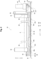
Figure 3] Figure 3 is a plan view showing the left half of the workpiece conveying wheeled platform. - [
Figure 4] Figure 4 is a perspective view showing the workpiece conveying wheeled platform. - [
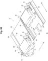
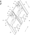
Figure 5A] Figure 5A is a perspective view showing an operation of the workpiece conveying wheeled platform. - [
Figure 5B] Figure 5B is a perspective view showing an operation of the workpiece conveying wheeled platform. - [
Figure 5C] Figure 5C is a perspective view showing an operation of the workpiece conveying wheeled platform. - [
Figure 5D] Figure 5D is a perspective view showing an operation of the workpiece conveying wheeled platform. - An embodiment will be described with reference to
Figures 1 to 5D . - Note that the "front-rear direction" is one of the horizontal directions, and is the direction in which a workpiece is conveyed by a workpiece conveying wheeled platform. The "left-right direction" is a horizontal direction orthogonal to the front-rear direction, and is a lateral direction of the workpiece conveying wheeled platform or a press brake. In the drawings, "FF", "FR", "L", "R", "U" and "D" indicate a forward direction, a backward direction, a left direction, a right direction, an upward direction, and a downward direction, respectively.
- As shown in
Figure 1 , abending system 10 according to the present embodiment is a working system that continuously bends a plate-shaped workpiece (a sheet metal) W. Thebending system 10 includes apress brake 12 as a working machine that bends the workpiece W by a collaboration between a punch tool (not shown) and a die tool (not shown). - A
guide frame 14 extending in the left-right direction is provided in a vicinity of a front of thepress brake 12. Theguide frame 14 includes abending robot 16, so as to be movable in the left-right direction, as a loading machine for supplying the workpiece W to thepress brake 12. In other words, thebending robot 16 is provided in the vicinity of the front of thepress brake 12 so as to be movable in the left-right direction via theguide frame 14. In addition to supplying the workpiece W to thepress brake 12, thebending robot 16 assists in bending the workpiece W. Thebending robot 16 carries out a bent product (not shown) to a product pallet (not shown) that is arranged in a carry-out area TA on the right front side of theguide frame 14. Thebending robot 16 has a publicly known configuration, for example, shown in Patent Literature 2, and includes an articulatedrobot arm 18 and arobot hand 20, which is provided at the distal end of therobot arm 18 and used as a workpiece suction unit for sucking the workpiece W. - A
safety fence 22 for ensuring safety in bending the workpiece W is provided in a periphery of the operating range of thebending robot 16. Thesafety fence 22 includes a plurality of doors (not shown) for allowing a pallet jack HL (seeFigure 5C ) or a forklift (not shown) to pass. - In a vicinity of a front of the bending
robot 16, a workpiece conveyingwheeled platform 24 for conveying the workpiece W from a setup area (a setting area) SA to a pickup area GA along the front-rear direction, which is the predetermined direction, is provided. The setup area SA is positioned outside thesafety fence 22 and is an area for setting up (setting) the workpieces W stacked on the pallet P. The pickup area GA is positioned inside thesafety fence 22 and is an area for sucking and picking up an uppermost workpiece W from among a plurality of the workpieces W with the bending robot 16 (the robot hand 20). Then, the specific configuration of the workpiece conveyingwheeled platform 24 is as follows. - As shown in
Figures 1 to 4 , a base plate (an attachment plate) 26 extending in the left-right direction (the lateral direction) is installed in the vicinity of the front of the bendingrobot 16, and the upper surface of thebase plate 26 corresponds to an installation surface IS on a floor. The front side portion of thebase plate 26 is positioned outside thesafety fence 22, and the rear side portion of thebase plate 26 is positioned inside thesafety fence 22.Notches 26n for two wheels for allowing wheels HLb on the distal end of forks HLa of the pallet jack HL to enter are formed on the front end side of the right side portion and the front end side of the left side portion of thebase plate 26, respectively. - Sliders (wheeled platform main bodies) 28 that move in the front-rear direction between the setup area SA and the pickup area GA are provided on the upper side of the left side portion and the upper side of the right side portion of the
base plate 26, respectively. Each of thesliders 28 is recessed downward to form a placingpart 28a for placing the pallet P thereon. The upper surface and the lower surface of the placingpart 28a of theslider 28 are formed as flat surfaces. The lower surface of the placingpart 28a is close to the upper surface of thebase plate 26 that corresponds to the installation surface IS on the floor. The recessed depth of the placingpart 28a is set to a depth corresponding to a height of the pallet P, for example, set to a depth equal to the height of the pallet P. In addition, on the front end side of the placingpart 28a,notches 28n for the two forks for allowing the forks HLa of the pallet jack HL to enter are formed. Thenotch 28n is matched to thenotch 26n of thebase plate 26. - Note that the recessed depth of the placing
part 28a does not necessarily have to be set to the depth equal to the height of the pallet P as long as it is set to the depth corresponding to the height of the pallet P. - A plurality of auxiliary rollers 30 (see
Figure 3 ) that roll on the upper surface of thebase plate 26 are rotatably provided at the center portion in the left-right direction (the lateral direction) of the placingpart 28a. As a result, the lower surface of the placingpart 28a can be brought closer to the upper surface of thebase plate 26 without bringing theslider 28 into contact with thebase plate 26. - Note that the
auxiliary rollers 30 may be rotatably provided on both end sides in the left-right direction of the placingpart 28a. An intermediate plate (not shown) harder than thebase plate 26 or a flat roller cage (not shown) may be interposed between thebase plate 26 and theslider 28. - A
first guide mechanism 32 that supports theslider 28 so as to be movable in the front-rear direction is arranged on the right side (one side in the lateral direction) of the placingpart 28a. Specifically, afirst guide rail 34 extending in the front-rear direction is provided, on part of the upper surface of thebase plate 26, on the right side of the placingpart 28a. In addition, aguide block 36 that is guided by thefirst guide rail 34 and is movable in the front-rear direction is provided on the right side of the placingpart 28a. The movement of theguide block 36 is restricted in the left-right direction with respect to thefirst guide rail 34. - A
second guide mechanism 38 that supports theslider 28 so as to be movable in the front-rear direction is arranged on the left side (the other side in the lateral direction) of the placingpart 28a. Specifically, asecond guide rail 40 extending in the front-rear direction is provided, on part of the upper surface of thebase plate 26, on the left side of the placingpart 28a. Aguide roller 42 that rolls on thesecond guide rail 40 is rotatably provided on the left side of the placingpart 28a. - Note that in lieu of the
guide roller 42, thesecond guide mechanism 38 may include a guide block that is provided on the left side of the placingpart 28a, is guided by thesecond guide rail 40, and is movable in the front-rear direction. - A
drive mechanism 44 for moving theslider 28 in the front-rear direction is arranged on the right side of the placingpart 28a. Specifically, a gearedmotor 46, which is a type of an electric motor as a moving actuator, is provided on the right side of the placingpart 28a. Arack member 48 extending in the front-rear direction is provided, on part of the upper surface of thebase plate 26, on the right side of the placingpart 28a. Apinion 52 that is engaged with therack member 48 is connected to anoutput shaft 50 of the gearedmotor 46. - Note that the
drive mechanism 44 may include an electric motor other than the gearedmotor 46. In lieu of therack member 48 and thepinion 52, thedrive mechanism 44 may include a ball screw extending in the front-rear direction and a nut member screwed into the ball screw. Thedrive mechanism 44 may include a hydraulic cylinder as a moving actuator in lieu of the electric motor such as the gearedmotor 46. Instead of arranging thedrive mechanism 44 on the right side of the placingpart 28a, another driving mechanism for moving theslider 28 in the front-rear direction may be arranged on the left side or both of the left and right sides of the placingpart 28a. - A first stopper (not shown) and a second stopper (not shown) are provided, on part of the upper surface of the
base plate 26, at appropriate positions on the left side of the placingpart 28a, so as to be separated in the front-rear direction. The first stopper prevents theslider 28 from moving forward beyond a predetermined position of the setup area SA. The second stopper prevents theslider 28 from moving backward beyond a predetermined position of the pickup area GA. In addition, a first sensor (not shown) and a second sensor (not shown) are provided, on part of the upper surface of thebase plate 26, at appropriate positions on the right side of the placingpart 28a, so as to be separated in the front-rear direction. The first sensor detects that theslider 28 is positioned at the predetermined position of the setup area SA. The second sensor detects that theslider 28 is positioned at the predetermined position of the pickup area GA. Further, a cable carrier (not shown) and a cable duct (not shown) are arranged, on part of the upper surface of thebase plate 26, at appropriate positions on the right side of the placingpart 28a. - A placing
plate 54 having an L shape in a plan view is provided from the rear portion to the right portion of the placingpart 28a. A plurality ofmagnet floaters 56 are erected on the placingplate 54. The magnet floaters 56 levitate, by magnetic force, the uppermost workpiece W from among the plurality of workpieces W stacked on the pallet P. Themagnet floater 56 has a publicly known configuration shown in Patent Literature 3. In addition, anair separator 58 is provided on the side portion of any of themagnet floaters 56. Theair separator 58 separates, by jet pressure of air, the uppermost workpiece W from among the plurality of workpieces W stacked on the pallet P. Theair separator 58 has a publicly known configuration shown in Patent Literature 3. A plurality of abuttingposts 60 against which the pallet P can be abutted are erected in a vicinity of the placingplate 54 in the placingpart 28a. - Note that the placing
plate 54 may be provided to thebase plate 26 instead of being provided to the placingpart 28a. When the uppermost workpiece W is picked up by using a camera (not shown) that captures an image of the uppermost workpiece W from above, the plurality ofmagnet floaters 56 and theair separator 58 may be omitted from the configuration of the workpiece conveyingwheeled platform 24. - A plurality of shutters (not shown) for opening and closing a part of the
safety fence 22 are provided on the upper surface of thebase plate 26. Each of the shutters is configured to switch the setup area SA and the pickup area GA from a communication state to a cutoff state when theslider 28 is moved in the front-rear direction. The communication state is a state in which the setup area SA and the pickup area GA are in communication. The cutoff state is a state in which the setup area SA and the pickup area GA are cut off. - Subsequently, the overall operation of the
bending system 10 and the particular effect of the workpiece conveyingwheeled platform 24 will be described. - As shown in
Figures 1 and5A , with theslider 28 on the right side being positioned in the pickup area GA, the bendingrobot 16 picks up the uppermost workpiece from the workpieces W that are stacked, via the pallet P, on the placingpart 28a of theslider 28 on the right side. Next, the bendingrobot 16 supplies the workpiece W, which is picked up, to thepress brake 12. Then, with the bendingrobot 16 assisting in bending the workpiece W, the workpiece W is bent by the collaboration between the punch tool and the die tool of thepress brake 12. Further, the bendingrobot 16 carries out the bent product to the product pallet. By repeating the operation described above, the workpieces W stacked via the pallet P on the placingpart 28a of theslider 28 on the right side are continuously bent. - In the meantime, as shown in
Figure 5B , with theslider 28 on the left side being positioned in the setup area SA, the pallet P on which the workpieces W are stacked by the pallet jack HL is moved backward and positioned above the placingpart 28a of theslider 28 on the left side. Next, by lowering the forks HLa of the pallet jack HL to place the pallet P on the placingpart 28a on the left side, the workpieces W stacked on the pallet P are set up. Further, as shown inFigure 5C , the pallet jack HL is moved forward to be separated from theleft slider 28. Then, as shown inFigure 5D , thepinion 52 on the left side (seeFigure 2 ) is rotated in the positive direction by driving the gearedmotor 46 on the left side so that theslider 28 on the left side is moved from the setup area SA to the pickup area GA. In this manner, the workpieces W stacked via the pallet P on the placingpart 28a of theslider 28 on the left side are prepared to be bent. - Note that when the workpieces W stacked on the pallet P placed on the placing
part 28a of theslider 28 on the left side are continuously bent, the same operation as that of the bending process on the right side, which is described above, is executed. In addition, when the workpieces W stacked on the pallet P placed on the placingpart 28a of theslider 28 on the right side are prepared to be bent, the same operation as that of the preparation on the left side, which is described above, is executed. - In the configuration of the workpiece conveying
wheeled platform 24, as described above, theslider 28 is recessed downward to form the placingpart 28a for placing the pallet P. In addition, the recessed depth of the placingpart 28a is set to the depth corresponding to the height of the pallet P. Thefirst guide mechanism 32 and thedrive mechanism 44 are respectively arranged on the right side of the placingpart 28a, and thesecond guide mechanism 38 is arranged on the left side of the placingpart 28a. As a result, it is possible to lower the height from the upper surface of thebase plate 26, which corresponds to the installation surface IS on the floor, to the upper surface of the placingpart 28a. Accordingly, it is possible to increase the stacking capacity of the workpieces W in the workpiece conveyingwheeled platform 24. According to the present embodiment, it is possible to reduce the frequency of setting up the workpieces W for the workpiece conveyingwheeled platform 24 so as to enhance the workability. - In addition, in the configuration of the workpiece conveying
wheeled platform 24, the lower surface of the placingpart 28a is close to the upper surface of thebase plate 26 as described above. Thenotches 28n for the two forks HLa are formed on the front end side of the placingpart 28a. Therefore, when the pallet P is placed on the placingpart 28a or the pallet P is picked up from the placingpart 28a, the amount of a vertical movement of the forks HLa can be reduced. Therefore, according to the present embodiment, the workpiece W can be set up by using the simple pallet jack HL having a small capable amount of the vertical movement of the forks HLa. - Further, in the configuration of the workpiece conveying
wheeled platform 24, as described above, theguide block 36 that is guided by thefirst guide rail 34 so as to be movable in the front-rear direction is provided on the right side of the placingpart 28a. Theguide roller 42 that rolls on thesecond guide rail 40 is rotatably provided on the left side of the placingpart 28a. As a result, even if an undulation (a slight deformation in the vertical direction) is generated on the upper surface of thebase plate 26 that corresponds to the installation surface IS on the floor, it is possible to move theslider 28 in the front-rear direction while absorbing the undulation. Therefore, according to the present embodiment, it is possible to stabilize the operation of the workpiece conveyingwheeled platform 24. - The workpiece conveying
wheeled platform 24 according to the present embodiment includes theslider 28 that is movable between the setup area SA and the pickup area GA, theguide mechanisms slider 28, and thedrive mechanism 44 that moves theslider 28 in the predetermined direction described above. Theslider 28 is recessed to form the placingpart 28a for placing the pallet P. Theguide mechanisms part 28a, respectively. Thedrive mechanism 44 is arranged on at least one side in the above-described lateral direction of the placingpart 28a. Therefore, according to the workpiece conveyingwheeled platform 24 related to the present embodiment, it is possible to shorten the height from the installation surface on the floor to the upper surface of the placingpart 28a. Then, the stacking capacity of the workpieces W in the workpiece conveyingwheeled platform 24 can be increased. - Since the stacking capacity of the workpieces W can be increased, the frequency of setting up the workpieces W for the workpiece conveying
wheeled platform 24 can be reduced. As a result, the workability can be enhanced. - In addition, in the workpiece conveying
wheeled platform 24 according to the present embodiment, the recessed depth of the placingpart 28a is set to the depth corresponding to the height of the pallet P. Therefore, the pallet P can be easily placed on the placingpart 28a, and the workability can be further enhanced. - In addition, in the workpiece conveying
wheeled platform 24 according to the present invention, the placingpart 28a is arranged close to the installation surface IS on the floor. Therefore, when the pallet P is placed on the placingpart 28a (or when the pallet P is picked up from the placingpart 28a), the vertical movement amount of the pallet P can be reduced and the workpieces W can be set up with the pallet jack HL. - Here, the
notches 28n for allowing the forks HLa of the pallet jack HL to enter are formed on the placingpart 28a. This fact also allows the vertical movement amount of the pallet P to be smaller, which makes the setup of the workpiece W by the pallet jack HL easy. - Further, since the
auxiliary rollers 30 that roll on the installation surface IS on the floor are provided to the placingpart 28a, it is possible to bring the lower surface of the placingpart 28a close to the upper surface of thebase plate 26 without bringing theslider 28 into contact with thebase plate 26. As a result, the workability can be further improved. - In addition, the
guide mechanisms first guide mechanism 32 and thesecond guide mechanism 38. Thefirst guide mechanism 32 includes thefirst guide rail 34 and theguide block 36 that are described above. Thesecond guide mechanism 38 includes thesecond guide rail 40 and theguide roller 42 that are described above. Therefore, theslider 28 can be easily slid in the predetermined direction, and the workability can be further enhanced. - The working
system 10 according to the present embodiment includes the working machine (the press brake) 12 for processing the workpiece W, the loading machine (the bending robot) 16 for supplying the workpiece W to the workingmachine 12, and the workpiece conveyingwheeled platform 24 described above. Therefore, according to the workingsystem 10 related to the present embodiment, the same effect as that of the workpiece conveyingwheeled platform 24 described above is brought about. - Note that the present invention is not limited to the descriptions of the present embodiment described above but rather only to the appended claims. The present invention can be executed in various modes, for example, the technical idea applied to the
bending system 10 can be applied to a working system other than the bendingsystem 10.
Claims (5)
- A workpiece conveying wheeled platform (24), comprising:a slider (28) provided in a vicinity of a loading machine (16) for supplying a workpiece (W) to a working machine (12), the slider (28) being movable in a predetermined direction between a setup area (SA) for setting up a plurality of workpieces (W) stacked on a pallet (P) and a pickup area (GA) for picking up an uppermost workpiece (W) from among the plurality of workpieces (W) with the loading machine (16), the slider (28) being recessed to form a placing part (28a) for placing the pallet (P);guide mechanisms (32, 38) respectively arranged to both sides of the placing part (28a) in a lateral direction orthogonal to the predetermined direction of the slider (28) and configured to support the slider (28) so as to be movable in the predetermined direction; anda drive mechanism (44) arranged to at least one side of the placing part (28a) in the lateral direction of the slider (28) and configured to move the slider (28) in the predetermined direction,wherein the placing part (28a) of the slider (28) is close to an installation surface (IS) on a floor,characterized in thata notch (28n) for allowing a fork (HLa) of a pallet jack (HL) to enter is formed on the placing part (28a) of the slider (28).
- The workpiece conveying wheeled platform (24) according to claim 1, further comprising:the pallet (P) placed on the placing part (28a), whereina recessed depth of the placing part (28a) of the slider (28) is set to a depth corresponding to a height of the pallet (P).
- The workpiece conveying wheeled platform (24) according to claim 1 or 2, further comprising an auxiliary roller (30) provided to the placing part (28a) of the slider (28) and configured to roll on the installation surface (IS) on the floor.
- The workpiece conveying wheeled platform (24) according to any one of claims 1 to 3, whereinthe guide mechanisms (32, 38) include a pair of a first guide mechanism (32) and a second guide mechanism (38),the first guide mechanism (32) includes:a first guide rail (34) provided, on part of the installation surface (IS) on the floor, on one side in the lateral direction of the placing part (28a) of the slider (28), and extending in the predetermined direction; anda guide block (36) provided on the one side in the lateral direction of the placing part (28a) of the slider (28), and configured to be guided by the first guide rail (34) so as to be movable in the predetermined direction, andthe second guide mechanism (38) includes:a second guide rail (40) provided, on part of the installation surface (IS) on the floor, on another side in the lateral direction of the placing part (28a) of the slider (28), and extending in the predetermined direction; anda guide roller (42) provided on the other side in the lateral direction of the placing part (28a) of the slider (28), and configured to roll on the second guide rail (40) in the predetermined direction.
- A working system (10), comprising:a working machine (12) configured to process a workpiece (W);a loading machine (16) configured to supply the workpiece (W) to the working machine (12); andthe workpiece conveying wheeled platform (24) according to any one of claims 1 to 4.
Applications Claiming Priority (2)
| Application Number | Priority Date | Filing Date | Title |
|---|---|---|---|
| JP2020138692A JP7489260B2 (en) | 2020-08-19 | 2020-08-19 | Work transport vehicle and processing system |
| PCT/JP2021/029704 WO2022039096A1 (en) | 2020-08-19 | 2021-08-12 | Workpiece conveying wheeled platform and working system |
Publications (3)
| Publication Number | Publication Date |
|---|---|
| EP4201544A1 EP4201544A1 (en) | 2023-06-28 |
| EP4201544A4 EP4201544A4 (en) | 2024-02-21 |
| EP4201544B1 true EP4201544B1 (en) | 2025-05-21 |
Family
ID=80322732
Family Applications (1)
| Application Number | Title | Priority Date | Filing Date |
|---|---|---|---|
| EP21858243.5A Active EP4201544B1 (en) | 2020-08-19 | 2021-08-12 | Workpiece conveying wheeled platform and working system |
Country Status (5)
| Country | Link |
|---|---|
| US (1) | US12600000B2 (en) |
| EP (1) | EP4201544B1 (en) |
| JP (1) | JP7489260B2 (en) |
| CN (1) | CN115884839A (en) |
| WO (1) | WO2022039096A1 (en) |
Families Citing this family (2)
| Publication number | Priority date | Publication date | Assignee | Title |
|---|---|---|---|---|
| JP7365464B1 (en) * | 2022-07-22 | 2023-10-19 | 株式会社アマダ | Work supply system, work supply method and work supply program |
| CN121042893B (en) * | 2025-09-11 | 2026-02-13 | 东营贝特尔机械科技有限公司 | A steel-aluminum composite wheel and its production apparatus |
Family Cites Families (43)
| Publication number | Priority date | Publication date | Assignee | Title |
|---|---|---|---|---|
| SE447238B (en) | 1985-04-16 | 1986-11-03 | Hymo Ab | DEVICE FOR A HYDRAULIC LIFT TABLE OF SAXT TYPE WHICH TABLE IS E-FORM |
| US5190434A (en) * | 1989-03-14 | 1993-03-02 | Canon Kabushiki Kaisha | Article supplier |
| JP3283562B2 (en) * | 1992-02-28 | 2002-05-20 | 株式会社アマダ | Plate loading machine for plate processing machine |
| IT1257209B (en) * | 1992-05-29 | 1996-01-10 | Comau Spa | UNIT FOR THE SUPPLY OF SEMI-FINISHED PRODUCTS TO A FORMING MACHINE, IN PARTICULAR A PRESS. |
| JP3002622U (en) * | 1994-03-31 | 1994-09-27 | 株式会社牧野フライス製作所 | Pallet changer |
| JPH08258986A (en) * | 1995-03-22 | 1996-10-08 | Zen Nikku Motor Service Kk | Automatic transferring device for air cargo |
| JPH10202438A (en) * | 1997-01-20 | 1998-08-04 | Kanto Auto Works Ltd | Part takeout device |
| JPH10309646A (en) * | 1997-05-08 | 1998-11-24 | Seibu Electric & Mach Co Ltd | Pallet transfer device |
| JPH1128528A (en) * | 1997-07-04 | 1999-02-02 | Amada Eng Center:Kk | Method for carrying-in work in punching press and device therefor |
| JP4036926B2 (en) * | 1997-08-27 | 2008-01-23 | 松下電器産業株式会社 | LAMINATED MANUFACTURING METHOD AND ITS MANUFACTURING DEVICE |
| JP3488072B2 (en) * | 1998-01-08 | 2004-01-19 | 株式会社名機製作所 | Apparatus and method for managing carrier plate in press machine |
| JPH11300441A (en) * | 1998-04-22 | 1999-11-02 | Amada Co Ltd | Loader and unloader device having shift function |
| JP2000094256A (en) * | 1998-09-21 | 2000-04-04 | Aichi Corp | Pallet transfer type work transfer device and work loading / unloading device |
| JP2000167742A (en) * | 1998-12-02 | 2000-06-20 | Yasuyuki Moriyama | Thermal cutting machining device |
| JP2001038437A (en) * | 1999-07-28 | 2001-02-13 | Amada Co Ltd | Material carrying-in device |
| JP2001113392A (en) * | 1999-10-14 | 2001-04-24 | Amada Co Ltd | Plate carry-in/carry-away device in thermal cutting machine |
| JP2001259956A (en) * | 2000-03-13 | 2001-09-25 | Cnk:Kk | Fall-down preventing device for track truck |
| JP2002153929A (en) * | 2000-11-24 | 2002-05-28 | Amada Co Ltd | Work feed apparatus |
| JP4242126B2 (en) * | 2002-09-02 | 2009-03-18 | 株式会社アマダ | Workpiece supply device for plate processing machine |
| JP2005103662A (en) * | 2003-09-26 | 2005-04-21 | Nippei Toyama Corp | Work transfer device |
| JP2006182564A (en) * | 2004-12-03 | 2006-07-13 | Amada Co Ltd | Method for stacking work on pallet and its device as well as shelf device and skid |
| EP2217515B1 (en) * | 2007-12-04 | 2011-10-26 | Dieter Faude | Palletizing device and method for loading and/or unloading pallets |
| CN102408011B (en) * | 2010-09-24 | 2013-08-28 | 鸿富锦精密工业(深圳)有限公司 | Feeding device |
| EP2676768B1 (en) * | 2011-02-15 | 2016-04-13 | Makino Milling Machine Co., Ltd. | System of a machine tool for transporting a pallet |
| CN102416961A (en) | 2011-11-02 | 2012-04-18 | 南车二七车辆有限公司 | Railway vehicle capable of loading containers in single or double layers |
| WO2014130937A1 (en) * | 2013-02-24 | 2014-08-28 | Intelligrated Headquaters Llc | Goods to robot for order fulfillment |
| JP2014172047A (en) * | 2013-03-06 | 2014-09-22 | Amada Co Ltd | Workpiece conveyance method and workpiece conveyance system |
| US9393686B1 (en) * | 2013-03-15 | 2016-07-19 | Industrial Perception, Inc. | Moveable apparatuses having robotic manipulators and conveyors to facilitate object movement |
| US8919360B1 (en) * | 2013-05-14 | 2014-12-30 | Gilbert Frank Ransley | Cabinet washer and rack system |
| JP5836464B1 (en) * | 2014-10-09 | 2015-12-24 | 株式会社アマダマシンツール | Machine Tools |
| JP2017024140A (en) * | 2015-07-27 | 2017-02-02 | 三菱重工業株式会社 | Positioning system and positioning method |
| JP2017109285A (en) * | 2015-12-18 | 2017-06-22 | 村田機械株式会社 | Workpiece conveyance system, laser processing system, and workpiece conveyance method |
| JP6622598B2 (en) | 2016-01-14 | 2019-12-18 | 株式会社アマダホールディングス | Robot hand, articulated robot, and material loading method |
| JP6667316B2 (en) | 2016-02-22 | 2020-03-18 | 株式会社アマダホールディングス | Air separator |
| JP2018126794A (en) * | 2017-02-06 | 2018-08-16 | 株式会社アマダホールディングス | Workpiece conveyance control device, workpiece detection method, and workpiece supply device |
| CN110662707B (en) | 2017-03-23 | 2021-12-14 | 伯克希尔格雷股份有限公司 | System and method for processing objects including automatically moving matrix boxes |
| CN107054960A (en) | 2017-04-24 | 2017-08-18 | 深圳市鸿鹭工业设备有限公司 | A kind of split type four-way shuttle and products storage circulation system |
| DE102017113500B4 (en) * | 2017-06-20 | 2023-05-17 | Logistik Service GmbH | transport system |
| US10583991B2 (en) * | 2018-02-20 | 2020-03-10 | Toyota Motor Engineering & Manufacturing North America, Inc. | Slide rail assemblies for moving objects on a transfer path, conveyor assemblies having slide rail assemblies, and methods of moving objects on a transfer path |
| US10898981B2 (en) * | 2018-12-19 | 2021-01-26 | Amada Holdings Co., Ltd. | Workpiece storage device and workpiece loading method |
| DE102019101310B4 (en) | 2019-01-18 | 2021-01-14 | Andreas Klasen | Dock leveler and method for reloading a load between two spaced depots |
| CN209522153U (en) | 2019-01-31 | 2019-10-22 | 深圳市海柔创新科技有限公司 | A kind of transfer robot and its pallet fork component |
| JP6616919B2 (en) | 2019-09-05 | 2019-12-04 | 株式会社アマダホールディングス | Work supply device |
-
2020
- 2020-08-19 JP JP2020138692A patent/JP7489260B2/en active Active
-
2021
- 2021-08-12 WO PCT/JP2021/029704 patent/WO2022039096A1/en not_active Ceased
- 2021-08-12 CN CN202180050616.8A patent/CN115884839A/en active Pending
- 2021-08-12 EP EP21858243.5A patent/EP4201544B1/en active Active
- 2021-08-12 US US18/018,463 patent/US12600000B2/en active Active
Also Published As
| Publication number | Publication date |
|---|---|
| EP4201544A1 (en) | 2023-06-28 |
| WO2022039096A1 (en) | 2022-02-24 |
| JP7489260B2 (en) | 2024-05-23 |
| EP4201544A4 (en) | 2024-02-21 |
| US20230286094A1 (en) | 2023-09-14 |
| US12600000B2 (en) | 2026-04-14 |
| CN115884839A (en) | 2023-03-31 |
| JP2022034814A (en) | 2022-03-04 |
Similar Documents
| Publication | Publication Date | Title |
|---|---|---|
| CN111229926B (en) | Automatic change fork panel beating production line | |
| US9352917B2 (en) | Method for removing a substantially planar work piece from the top of a stack of work pieces | |
| CN109533973B (en) | Automatic blanking machine for glass | |
| CN109516197B (en) | Automatic plate splitting feeding and discharging device | |
| US12600000B2 (en) | Workpiece conveying wheeled platform and working system | |
| US20240083697A1 (en) | Stacking device, automation module and method | |
| CN213562936U (en) | Automatic cutting and feeding and discharging production line for film-coated plates | |
| US20200079630A1 (en) | Driverless transporter | |
| CN112845936A (en) | Automatic bending production line for packaging boxes | |
| CN115156363A (en) | Stamping device with feeding structure | |
| JP2008184316A (en) | Rack device, and method for placing workpiece on product pallet | |
| EP0992318A2 (en) | Device and method of feeding panels onto a cutting system | |
| KR101733983B1 (en) | High-efficient press system | |
| CN216426154U (en) | A manipulator for pressing from both sides paper | |
| KR101665868B1 (en) | Mold system using two-row transfer device | |
| KR101875374B1 (en) | Method of pressing and high-efficient press system | |
| JPH07155874A (en) | Work feeding device in plate working machine | |
| CN217192162U (en) | Automatic stamping forming production system for automobile transmission suspension support parts | |
| KR101694339B1 (en) | Supplying apparatus of blank | |
| CN223534276U (en) | Automatic wire frame identification and guidance system | |
| CN223981084U (en) | A heavy-duty automatic bending workstation | |
| CN116900874B (en) | A fully automated vehicle-mounted glass grinding and milling production line | |
| JPH0650424Y2 (en) | Work transfer device for plate processing machine | |
| CN213080469U (en) | Automatic loading and unloading device of laser cutting machine | |
| JP4923752B2 (en) | Board processing system |
Legal Events
| Date | Code | Title | Description |
|---|---|---|---|
| STAA | Information on the status of an ep patent application or granted ep patent |
Free format text: STATUS: THE INTERNATIONAL PUBLICATION HAS BEEN MADE |
|
| PUAI | Public reference made under article 153(3) epc to a published international application that has entered the european phase |
Free format text: ORIGINAL CODE: 0009012 |
|
| STAA | Information on the status of an ep patent application or granted ep patent |
Free format text: STATUS: REQUEST FOR EXAMINATION WAS MADE |
|
| 17P | Request for examination filed |
Effective date: 20230119 |
|
| AK | Designated contracting states |
Kind code of ref document: A1 Designated state(s): AL AT BE BG CH CY CZ DE DK EE ES FI FR GB GR HR HU IE IS IT LI LT LU LV MC MK MT NL NO PL PT RO RS SE SI SK SM TR |
|
| DAV | Request for validation of the european patent (deleted) | ||
| DAX | Request for extension of the european patent (deleted) | ||
| A4 | Supplementary search report drawn up and despatched |
Effective date: 20240122 |
|
| RIC1 | Information provided on ipc code assigned before grant |
Ipc: B21D 43/10 20060101ALN20240116BHEP Ipc: B21D 5/00 20060101ALN20240116BHEP Ipc: B21D 43/13 20060101ALI20240116BHEP Ipc: B65G 25/06 20060101ALI20240116BHEP Ipc: B30B 15/30 20060101ALI20240116BHEP Ipc: B23Q 7/00 20060101ALI20240116BHEP Ipc: B21D 43/24 20060101ALI20240116BHEP Ipc: B21D 5/02 20060101AFI20240116BHEP |
|
| STAA | Information on the status of an ep patent application or granted ep patent |
Free format text: STATUS: EXAMINATION IS IN PROGRESS |
|
| 17Q | First examination report despatched |
Effective date: 20240905 |
|
| GRAP | Despatch of communication of intention to grant a patent |
Free format text: ORIGINAL CODE: EPIDOSNIGR1 |
|
| STAA | Information on the status of an ep patent application or granted ep patent |
Free format text: STATUS: GRANT OF PATENT IS INTENDED |
|
| RIC1 | Information provided on ipc code assigned before grant |
Ipc: B21D 43/10 20060101ALN20250122BHEP Ipc: B21D 5/00 20060101ALN20250122BHEP Ipc: B21D 43/13 20060101ALI20250122BHEP Ipc: B65G 25/06 20060101ALI20250122BHEP Ipc: B30B 15/30 20060101ALI20250122BHEP Ipc: B23Q 7/00 20060101ALI20250122BHEP Ipc: B21D 43/24 20060101ALI20250122BHEP Ipc: B21D 5/02 20060101AFI20250122BHEP |
|
| RIC1 | Information provided on ipc code assigned before grant |
Ipc: B21D 43/10 20060101ALN20250127BHEP Ipc: B21D 5/00 20060101ALN20250127BHEP Ipc: B21D 43/13 20060101ALI20250127BHEP Ipc: B65G 25/06 20060101ALI20250127BHEP Ipc: B30B 15/30 20060101ALI20250127BHEP Ipc: B23Q 7/00 20060101ALI20250127BHEP Ipc: B21D 43/24 20060101ALI20250127BHEP Ipc: B21D 5/02 20060101AFI20250127BHEP |
|
| INTG | Intention to grant announced |
Effective date: 20250205 |
|
| GRAS | Grant fee paid |
Free format text: ORIGINAL CODE: EPIDOSNIGR3 |
|
| GRAA | (expected) grant |
Free format text: ORIGINAL CODE: 0009210 |
|
| STAA | Information on the status of an ep patent application or granted ep patent |
Free format text: STATUS: THE PATENT HAS BEEN GRANTED |
|
| P01 | Opt-out of the competence of the unified patent court (upc) registered |
Free format text: CASE NUMBER: APP_12287/2025 Effective date: 20250313 |
|
| AK | Designated contracting states |
Kind code of ref document: B1 Designated state(s): AL AT BE BG CH CY CZ DE DK EE ES FI FR GB GR HR HU IE IS IT LI LT LU LV MC MK MT NL NO PL PT RO RS SE SI SK SM TR |
|
| REG | Reference to a national code |
Ref country code: GB Ref legal event code: FG4D |
|
| REG | Reference to a national code |
Ref country code: CH Ref legal event code: EP |
|
| REG | Reference to a national code |
Ref country code: DE Ref legal event code: R096 Ref document number: 602021031255 Country of ref document: DE |
|
| REG | Reference to a national code |
Ref country code: IE Ref legal event code: FG4D |
|
| REG | Reference to a national code |
Ref country code: NL Ref legal event code: MP Effective date: 20250521 |
|
| PG25 | Lapsed in a contracting state [announced via postgrant information from national office to epo] |
Ref country code: PT Free format text: LAPSE BECAUSE OF FAILURE TO SUBMIT A TRANSLATION OF THE DESCRIPTION OR TO PAY THE FEE WITHIN THE PRESCRIBED TIME-LIMIT Effective date: 20250922 Ref country code: FI Free format text: LAPSE BECAUSE OF FAILURE TO SUBMIT A TRANSLATION OF THE DESCRIPTION OR TO PAY THE FEE WITHIN THE PRESCRIBED TIME-LIMIT Effective date: 20250521 Ref country code: ES Free format text: LAPSE BECAUSE OF FAILURE TO SUBMIT A TRANSLATION OF THE DESCRIPTION OR TO PAY THE FEE WITHIN THE PRESCRIBED TIME-LIMIT Effective date: 20250521 |
|
| PGFP | Annual fee paid to national office [announced via postgrant information from national office to epo] |
Ref country code: DE Payment date: 20250820 Year of fee payment: 5 |
|
| REG | Reference to a national code |
Ref country code: LT Ref legal event code: MG9D |
|
| PG25 | Lapsed in a contracting state [announced via postgrant information from national office to epo] |
Ref country code: NO Free format text: LAPSE BECAUSE OF FAILURE TO SUBMIT A TRANSLATION OF THE DESCRIPTION OR TO PAY THE FEE WITHIN THE PRESCRIBED TIME-LIMIT Effective date: 20250821 Ref country code: GR Free format text: LAPSE BECAUSE OF FAILURE TO SUBMIT A TRANSLATION OF THE DESCRIPTION OR TO PAY THE FEE WITHIN THE PRESCRIBED TIME-LIMIT Effective date: 20250822 |
|
| PG25 | Lapsed in a contracting state [announced via postgrant information from national office to epo] |
Ref country code: PL Free format text: LAPSE BECAUSE OF FAILURE TO SUBMIT A TRANSLATION OF THE DESCRIPTION OR TO PAY THE FEE WITHIN THE PRESCRIBED TIME-LIMIT Effective date: 20250521 Ref country code: NL Free format text: LAPSE BECAUSE OF FAILURE TO SUBMIT A TRANSLATION OF THE DESCRIPTION OR TO PAY THE FEE WITHIN THE PRESCRIBED TIME-LIMIT Effective date: 20250521 |
|
| PG25 | Lapsed in a contracting state [announced via postgrant information from national office to epo] |
Ref country code: BG Free format text: LAPSE BECAUSE OF FAILURE TO SUBMIT A TRANSLATION OF THE DESCRIPTION OR TO PAY THE FEE WITHIN THE PRESCRIBED TIME-LIMIT Effective date: 20250521 |
|
| PG25 | Lapsed in a contracting state [announced via postgrant information from national office to epo] |
Ref country code: HR Free format text: LAPSE BECAUSE OF FAILURE TO SUBMIT A TRANSLATION OF THE DESCRIPTION OR TO PAY THE FEE WITHIN THE PRESCRIBED TIME-LIMIT Effective date: 20250521 |
|
| PG25 | Lapsed in a contracting state [announced via postgrant information from national office to epo] |
Ref country code: RS Free format text: LAPSE BECAUSE OF FAILURE TO SUBMIT A TRANSLATION OF THE DESCRIPTION OR TO PAY THE FEE WITHIN THE PRESCRIBED TIME-LIMIT Effective date: 20250821 |
|
| PG25 | Lapsed in a contracting state [announced via postgrant information from national office to epo] |
Ref country code: IS Free format text: LAPSE BECAUSE OF FAILURE TO SUBMIT A TRANSLATION OF THE DESCRIPTION OR TO PAY THE FEE WITHIN THE PRESCRIBED TIME-LIMIT Effective date: 20250921 |
|
| PG25 | Lapsed in a contracting state [announced via postgrant information from national office to epo] |
Ref country code: LV Free format text: LAPSE BECAUSE OF FAILURE TO SUBMIT A TRANSLATION OF THE DESCRIPTION OR TO PAY THE FEE WITHIN THE PRESCRIBED TIME-LIMIT Effective date: 20250521 |
|
| REG | Reference to a national code |
Ref country code: AT Ref legal event code: MK05 Ref document number: 1796358 Country of ref document: AT Kind code of ref document: T Effective date: 20250521 |
|
| PG25 | Lapsed in a contracting state [announced via postgrant information from national office to epo] |
Ref country code: SM Free format text: LAPSE BECAUSE OF FAILURE TO SUBMIT A TRANSLATION OF THE DESCRIPTION OR TO PAY THE FEE WITHIN THE PRESCRIBED TIME-LIMIT Effective date: 20250521 Ref country code: AT Free format text: LAPSE BECAUSE OF FAILURE TO SUBMIT A TRANSLATION OF THE DESCRIPTION OR TO PAY THE FEE WITHIN THE PRESCRIBED TIME-LIMIT Effective date: 20250521 Ref country code: DK Free format text: LAPSE BECAUSE OF FAILURE TO SUBMIT A TRANSLATION OF THE DESCRIPTION OR TO PAY THE FEE WITHIN THE PRESCRIBED TIME-LIMIT Effective date: 20250521 |
|
| PG25 | Lapsed in a contracting state [announced via postgrant information from national office to epo] |
Ref country code: CZ Free format text: LAPSE BECAUSE OF FAILURE TO SUBMIT A TRANSLATION OF THE DESCRIPTION OR TO PAY THE FEE WITHIN THE PRESCRIBED TIME-LIMIT Effective date: 20250521 |
|
| PG25 | Lapsed in a contracting state [announced via postgrant information from national office to epo] |
Ref country code: EE Free format text: LAPSE BECAUSE OF FAILURE TO SUBMIT A TRANSLATION OF THE DESCRIPTION OR TO PAY THE FEE WITHIN THE PRESCRIBED TIME-LIMIT Effective date: 20250521 |
|
| PG25 | Lapsed in a contracting state [announced via postgrant information from national office to epo] |
Ref country code: SK Free format text: LAPSE BECAUSE OF FAILURE TO SUBMIT A TRANSLATION OF THE DESCRIPTION OR TO PAY THE FEE WITHIN THE PRESCRIBED TIME-LIMIT Effective date: 20250521 |
|
| PG25 | Lapsed in a contracting state [announced via postgrant information from national office to epo] |
Ref country code: IT Free format text: LAPSE BECAUSE OF FAILURE TO SUBMIT A TRANSLATION OF THE DESCRIPTION OR TO PAY THE FEE WITHIN THE PRESCRIBED TIME-LIMIT Effective date: 20250521 |
|
| REG | Reference to a national code |
Ref country code: DE Ref legal event code: R097 Ref document number: 602021031255 Country of ref document: DE |
|
| PG25 | Lapsed in a contracting state [announced via postgrant information from national office to epo] |
Ref country code: RO Free format text: LAPSE BECAUSE OF FAILURE TO SUBMIT A TRANSLATION OF THE DESCRIPTION OR TO PAY THE FEE WITHIN THE PRESCRIBED TIME-LIMIT Effective date: 20250521 |
|
| REG | Reference to a national code |
Ref country code: CH Ref legal event code: H13 Free format text: ST27 STATUS EVENT CODE: U-0-0-H10-H13 (AS PROVIDED BY THE NATIONAL OFFICE) Effective date: 20260324 |
|
| PLBE | No opposition filed within time limit |
Free format text: ORIGINAL CODE: 0009261 |
|
| STAA | Information on the status of an ep patent application or granted ep patent |
Free format text: STATUS: NO OPPOSITION FILED WITHIN TIME LIMIT |
|
| PG25 | Lapsed in a contracting state [announced via postgrant information from national office to epo] |
Ref country code: MC Free format text: LAPSE BECAUSE OF FAILURE TO SUBMIT A TRANSLATION OF THE DESCRIPTION OR TO PAY THE FEE WITHIN THE PRESCRIBED TIME-LIMIT Effective date: 20250521 |
|
| REG | Reference to a national code |
Ref country code: CH Ref legal event code: L10 Free format text: ST27 STATUS EVENT CODE: U-0-0-L10-L00 (AS PROVIDED BY THE NATIONAL OFFICE) Effective date: 20260402 |
|
| PG25 | Lapsed in a contracting state [announced via postgrant information from national office to epo] |
Ref country code: LU Free format text: LAPSE BECAUSE OF NON-PAYMENT OF DUE FEES Effective date: 20250812 |
|
| PG25 | Lapsed in a contracting state [announced via postgrant information from national office to epo] |
Ref country code: CH Free format text: LAPSE BECAUSE OF NON-PAYMENT OF DUE FEES Effective date: 20250831 |
|
| 26N | No opposition filed |
Effective date: 20260224 |
|
| GBPC | Gb: european patent ceased through non-payment of renewal fee |
Effective date: 20250821 |