EP4201501A1 - Reinigungssystem zur abschnittsweisen reinigung einer batch-off anlage und verfahren zur abschnittsweisen reinigung einer batch-off anlage - Google Patents
Reinigungssystem zur abschnittsweisen reinigung einer batch-off anlage und verfahren zur abschnittsweisen reinigung einer batch-off anlage Download PDFInfo
- Publication number
- EP4201501A1 EP4201501A1 EP22212723.5A EP22212723A EP4201501A1 EP 4201501 A1 EP4201501 A1 EP 4201501A1 EP 22212723 A EP22212723 A EP 22212723A EP 4201501 A1 EP4201501 A1 EP 4201501A1
- Authority
- EP
- European Patent Office
- Prior art keywords
- foam
- batch
- mixture
- cleaning
- collection container
- Prior art date
- Legal status (The legal status is an assumption and is not a legal conclusion. Google has not performed a legal analysis and makes no representation as to the accuracy of the status listed.)
- Granted
Links
Images

Classifications
-
- B—PERFORMING OPERATIONS; TRANSPORTING
- B01—PHYSICAL OR CHEMICAL PROCESSES OR APPARATUS IN GENERAL
- B01D—SEPARATION
- B01D21/00—Separation of suspended solid particles from liquids by sedimentation
- B01D21/02—Settling tanks with single outlets for the separated liquid
- B01D21/04—Settling tanks with single outlets for the separated liquid with moving scrapers
-
- B—PERFORMING OPERATIONS; TRANSPORTING
- B01—PHYSICAL OR CHEMICAL PROCESSES OR APPARATUS IN GENERAL
- B01D—SEPARATION
- B01D21/00—Separation of suspended solid particles from liquids by sedimentation
- B01D21/24—Feed or discharge mechanisms for settling tanks
- B01D21/2433—Discharge mechanisms for floating particles
- B01D21/2438—Discharge mechanisms for floating particles provided with scrapers on the liquid surface for removing floating particles
-
- B—PERFORMING OPERATIONS; TRANSPORTING
- B01—PHYSICAL OR CHEMICAL PROCESSES OR APPARATUS IN GENERAL
- B01D—SEPARATION
- B01D21/00—Separation of suspended solid particles from liquids by sedimentation
- B01D21/24—Feed or discharge mechanisms for settling tanks
- B01D21/245—Discharge mechanisms for the sediments
- B01D21/2461—Positive-displacement pumps; Screw feeders; Trough conveyors
-
- B—PERFORMING OPERATIONS; TRANSPORTING
- B01—PHYSICAL OR CHEMICAL PROCESSES OR APPARATUS IN GENERAL
- B01D—SEPARATION
- B01D21/00—Separation of suspended solid particles from liquids by sedimentation
- B01D21/26—Separation of sediment aided by centrifugal force or centripetal force
Definitions
- the invention relates to a cleaning system for the section-by-section cleaning of a batch-off system according to the combination of features of patent claim 1.
- the invention also relates to a method for the section-by-section cleaning of a batch-off system using a cleaning system according to the invention according to the combination of features of patent claim 10.
- Batch-off systems are systems that are installed, for example, as a result of a rolling mill. With the help of a batch-off system, the rubber webs, which are produced using a calender process, are firstly cooled and secondly placed in easily manageable volumes.
- An anti-adhesion agent is applied by coating the rubber web with the anti-adhesion agent using a coating device.
- the coating device essentially comprises a dip tank through which the rubber sheet can be guided. In the dip tank is a G solution containing an anti-seize agent.
- the solution in the dip tank becomes contaminated during the course of the coating process.
- Several factors are known to contribute to contamination of the release agent solution.
- pieces of rubber or parts of the rubber sheets can get into the anti-adhesive solution due to mechanical stress.
- the anti-seize agent can precipitate and collect, for example, at the bottom of the coater.
- the chemical components that do not end up as a coating on the rubber sheeting go into solution.
- the object of the present invention to use the cleaning system to conserve resources such as water resources and to reuse or clean as high a proportion of the anti-adhesive solution as possible.
- the invention is based on the idea that a cleaning system according to the invention for cleaning a batch-off system at least in sections has at least one collection container for a mixture to be collected.
- the mixture to be collected contains at least anti-adhesive residues.
- the at least one collection container has at least one foam skimming device, the foam skimming device being designed to separate foam components of the mixture from liquid components of the mixture and to transport the foam components to a foam collection container. With the help of the formation of a foam skimming device, it is possible to carry out cleaning in sections, d. H. carry out at least one cleaning in a selected section of the batch-off system.
- the mixture to be collected preferably contains water and/or material sections or material particles of the rubber component to be processed in the batch-off system, in particular the rubber band.
- the anti-adhesion agent itself is preferably a mixture of a wide variety of chemicals. These can be inert minerals in combination with calcium stearate, detergents, antifoams and rust inhibitors.
- the anti-adhesive residues can thus contain components of the powder compositions mentioned.
- the foam skimming device has at least one wall or plate inclined in relation to the horizontal of the collecting container and a movable, in particular horizontally movable, spatula.
- a horizontal line of the collecting container is to be understood in particular as such an axis which runs parallel to a liquid surface formed in the collecting container.
- the inclined wall or the inclined plate is thus inclined to the horizontal and to the liquid surface formed in the collection container.
- An inclined wall is to be understood in particular as a wall or housing section of the collection container.
- a section of the collecting container itself is preferably designed to be inclined.
- An inclined plate is preferably a separately formed component connected to the receptacle.
- the spatula which can be moved, in particular horizontally, is, for example, a plastic element which can be moved above the inclined surface or inclined plate. Due to the, in particular horizontal, movement of the spatula, a foam component of the mixture formed on the liquid surface can be pushed along the inclined surface or inclined plate in the direction of an edge section of the collecting container, so that the foam component of the mixture is separated from liquid components of the mixture and becomes one Foam collection container can be transported. The foam is thus skimmed off at the collection container.
- the spatula may be generically referred to or configured as an elongate member that allows for sweeping motion over a liquid surface.
- a first collection container is preferably arranged below a coating device of the batch-off system.
- the coating device can be a dip tank or a dip tank.
- the mixture located in the immersion container or in the immersion basin, which has residues of anti-adhesive agent, can thus be discharged in a vertical direction downwards into the first collection container.
- a preferably at least second collection container can be arranged below a dripping zone of the batch-off system.
- the drying area of a batch-off system, in which the anti-adhesive agent initially on the rubber web can still drip off, is to be understood as a dripping zone.
- the at least one collecting container in particular the first collecting container, has a collecting section in the bottom section, in particular a conically shaped collecting section, which is designed to collect solids of the mixture.
- the solids of the mixture can be powder components of the anti-adhesion agent.
- the solids can be particles or material sections of the rubber sheet or rubber material to be treated in the batch-off system.
- such a recess is preferably formed in the bottom section, which is preferably formed in the vertical direction opposite to the foam skimming device of the collecting container, which depression can serve as a collecting section for the heavier solids of the mixture.
- the at least one collecting container in particular the first collecting container, can be fluidly connected to a centrifuge or to a centrifugal separator or to a screw conveyor.
- the collection container particularly in the area of the collection section, has a solids discharge opening through which the collected solids can be removed from the collection container and transported to a centrifuge or a centrifugal separator or a screw conveyor.
- the screw conveyor prefferably be designed in the collection container, in particular in the region of the collection section, so that the solids collected in the collection section can be transported out of the collection container.
- the foam collection container can have a filter device, in particular a sieve separator, which is designed to separate residual liquid from the foam component located in the foam collection container.
- the foam collection container can be fluidly connected to a waste collection container, the waste collection container preferably having a filter device, in particular a sieve separator, which is designed to separate residual liquid from the materials located in the waste collection container.
- a filter device in particular a sieve separator
- a rinsing and/or spraying device in a/the dripping zone of the batch-off system, which is designed to dilute the mixture to be collected in the dripping zone.
- the at least second collecting container which is formed in a/the dripping zone, is preferably designed as an elongate collecting container which has an inclined wall in one section.
- the inclined wall is itself formed by the collection container. Since the mixture to be collected in the area of the dripping zone has a lower viscosity than, for example, in the area of the coating device, it is advantageous to dilute the mixture to be collected in the dripping zone so that a foam can be skimmed off accordingly.
- a further aspect of the invention relates to a method for cleaning a batch-off plant in sections by means of a cleaning system according to the invention.
- the method according to the invention provides that, at least in sections, a mixture containing anti-adhesive residues is collected in at least one collection container, with the foam skimming device designed according to the invention separating foam components of the mixture from liquid components of the mixture, preferably regularly, and transporting the foam components to a foam collection container .
- the foam skimming device is activated at regular time intervals, the time interval being 20 minutes to 240 minutes, in particular 30 minutes to 120 minutes, in particular 45 minutes to 80 minutes.
- the cleaning system has a plurality of collection containers each with foam skimming devices, it is possible for the respective foam skimming devices to be activated in parallel or at different times.
- the advantage of activating several foam skimming devices at different times is that the foam components collected in each case can be continuously cleaned.
- the post-treatments or subsequent cleaning steps in connection with the foam components skimmed off in each case can be carried out more quickly in view of the smaller accumulated amounts of foam components in each case.
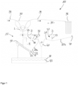
- FIG. 1 shows schematically the basic structure of a cleaning system 10 according to the invention for cleaning a batch-off system 100 in sections.
- a rubber sheet 99 is cooled and coated with an anti-adhesive agent, so that the rubber sheet 99 is transported further in a stacked or folded form 98 or can be processed.
- the batch-off system 100 has a coating device 90 .
- the coating device 90 is designed as a type of dip tank through which the rubber band 99 can be guided.
- An anti-adhesive solution L is located in the dip tank, so that the rubber web 99 can be coated with an appropriate anti-adhesive agent.
- the anti-adhesion agent solution is a mixture of water and anti-adhesion agent, the anti-adhesion agent being present, for example, in a concentration of 2 to 4% by weight, based on the total mixture.
- a mixture G containing anti-adhesive residues is collected in a collecting container 20a.
- the mixture G can contain, for example, rubber components or rubber particles.
- the collection container 20a also has a foam skimming device 30 .
- the foam skimming device 30 has at least one plate 32 inclined in relation to the horizontal 21 of the collecting container 20a and a movable spatula 33 .
- the spatula 33 can be moved horizontally in the moving direction D as shown by the arrow.
- a foam component S of the mixture G can be separated from the liquid components F of the mixture G with the aid of the horizontally movable gap 33 and transported to a foam collection container 40 .
- the first collecting container 20a is arranged below the coating device 90 in the vertical direction.
- the cleaning system 10 has a second collection container 20b.
- the second collection container 20b is arranged in the vertical direction below the dripping zone 95 of the batch-off system 100. Drops of the anti-adhesive agent can detach from the coated rubber strip 99 in the drip zone 95 .
- the second collection container 20b has an inclined wall 31 .
- the inclined wall 31 is part of the foam skimming device 30.
- a gap 33 is also formed in connection with the second collecting container 20b.
- the spatula 33 can also be moved in the direction of movement D. With a movement of the spatula 33 to the left, a foam component S can thus be transported to the foam collection container 40 .
- a liquid component F of the mixture G on the other hand, initially remains in the second collection container 20b.
- the inclined plate 32 is formed as a separate component.
- a foam skimming device 30 in order to form a foam skimming device 30, it is necessary to form a separate plate 32 in addition to forming a spatula 33.
- a wall of the collection container 20b itself is designed as an inclined surface or inclined wall 31 . It is therefore not necessary to form a separate plate here.
- a spray device 70 is preferably provided in the area of the second collecting container 20b, so that the drops of anti-adhesive agent collected by the second collecting container 20b can be diluted.
- the concentration of the anti-adhesive agent in the foam component S is around 50%, for example.
- the first collecting container 20a has a collecting section 23 in the bottom section 22 .
- the collection section 23 is designed to collect solids M of the mixture G.
- the collecting section 23 is formed, for example, by a cone-like shape of the base section 22 .
- the collection section 23 can also be referred to as a depression in the collection container 20a, in which solids M of the mixture G collect.
- the cleaning system 10 has a screw conveyor 50, with the help of which the solids M can be transported out of the first collecting container 20a.
- the solids M are preferably transported to a waste collection container 80 .
- This waste collection container can have a filter device, in particular a sieve separator 85 which is designed to separate residual liquid from the materials located in the waste collection container 80 .
- the solid M can be, for example, deposits of the precipitated anti-adhesive powder and rubber compound particles.
- the precipitated non-stick powder can be present in a concentration of about 75% at this stage.
- waste collection container 80 With the help of the waste collection container 80 and the additionally designed sieve separator 85, it is possible to separate residual liquid from collected waste materials again, so that this residual liquid can be returned to the batch-off system circuit.
- the foam component S of the foam collection container 40 is preferably also collected in the waste collection container 80 and separated again with the aid of the sieve separator 85 .
- the foam collection container 40 itself to have a filter device, in particular a sieve separator.
- This embodiment of the cleaning system 10 differs only in the alternative design of a centrifugal separator 60 instead of a screw conveyor 50.
- the solids M collected in the collecting container 20a can be separated again with regard to the liquid and solid components.
- the separated liquid fractions can be returned to the batch-off plant.
- the solids separated by means of the centrifugal separator 60 can be transported to the waste collection container 80 .
- a further separation or cleaning can be carried out here with the aid of a sieve separator 85 .
Landscapes
- Chemical & Material Sciences (AREA)
- Chemical Kinetics & Catalysis (AREA)
- Cleaning By Liquid Or Steam (AREA)
- Cleaning In General (AREA)
Abstract
wobei das Reinigungssystem (10) mindestens einen Auffangbehälter (20a, 20b) für ein zu sammelndes Gemisch (G), das mindestens Antihaftmittelrückstände enthält, aufweist, wobei der mindestens eine Auffangbehälter (20a, 20b) mindestens eine Schaumabschöpfvorrichtung (30) aufweist, wobei die Schaumabschöpfvorrichtung (30) dazu ausgebildet ist, Schaumbestandteile (S) des Gemisches (G) von Flüssigbestandteilen (F) des Gemisches (G) zu trennen und die Schaumbestandteile (S) zu mindestens einen Schaumsammelbehälter (40) zu transportieren.
Description
- Die Erfindung betrifft ein Reinigungssystem zur abschnittsweisen Reinigung einer Batch-Off Anlage gemäß Merkmalskombination des Patentanspruches 1. Des Weiteren betrifft die Erfindung ein Verfahren zur abschnittsweisen Reinigung einer Batch-Off Anlage mittels eines erfindungsgemäßen Reinigungssystems gemäß Merkmalskombination des Patentanspruches 10.
- Batch-Off Anlagen sind Anlagen, die beispielsweise in Folge eines Walzwerks installiert sind. Mit Hilfe einer Batch-Off Anlage werden die mittels eines Kalander-Prozesses hergestellten Gummibahnen zum einen abgekühlt und zum anderen in einfach handhabbare Volumina gelegt.
- Um die hergestellten Gummibahnen palettieren, falten bzw. aufeinanderlegen zu können, ist es notwendig, die Gummibahnen mit einem Antihaftmittel zu versehen. Das Auftragen eines Antihaftmittels erfolgt, indem die Gummibahn mittels einer Beschichtungsvorrichtung mit dem Antihaftmittel beschichtet wird. Die Beschichtungsvorrichtung umfasst im Wesentlichen einen Eintauchbehälter, durch den die Gummibahn geführt werden kann. In dem Eintauchbehälter ist ein G Lösung befindlich, die ein Antihaftmittel aufweist.
- Es zeigt sich jedoch, dass die in dem Eintauchbehälter befindliche Lösung im Laufe des Beschichtungsverfahrens verunreinigt wird. Es sind mehrere Faktoren bekannt, die eine Verunreinigung der Antihaftmittel-Lösung begünstigen. Zum einen können durch mechanische Beanspruchungen Gummistücke bzw. Teile der Gummibahnen in die Antihaftmittellösung gelangen. Aufgrund von Verdunstung und Zirkulation im System kann außerdem das Antihaftmittel ausfallen und sich beispielsweise am Boden der Beschichtungsvorrichtung sammeln. Des Weiteren ist es bekannt, dass die chemischen Bestandteile, die nicht als Beschichtung auf die Gummibahnen gelangen, in Lösung gehen. Diese genannten Faktoren führen dazu, dass sich zum einen am Boden der Beschichtungsvorrichtung Ablagerungen bilden und zum anderen auf der Flüssigkeitsoberfläche bzw. Lösungsoberfläche Schaum bildet. Die Schaumbildung kann unter Umständen in einem derartigen Maß erfolgen, dass ein Aus- bzw. Überlaufen der Antihaftmittellösung in der Beschichtungsvorrichtung bzw. an einem Eintauchbehälter erfolgt.
- Daher ist es bislang notwendig, manuell eine Batch-Off Anlage, insbesondere im Bereich der Beschichtungsvorrichtung durchzuführen. Hierzu ist es notwendig, die Batch-Off Anlage zu stoppen, während eine entsprechende Reinigung durchgeführt wird. Demnach kann während eines Reinigungsprozesses die Batch-Off Anlage nicht genutzt werden.
- Im Lichte der vorgenannten Nachteile des bekannten Standes der Technik ist es Aufgabe der vorliegenden Erfindung, ein Reinigungssystem zur abschnittsweisen Reinigung einer Batch-Off Anlage anzugeben, die eine einfache abschnittsweise Reinigung, beispielsweise im Bereich einer Beschichtungsvorrichtung, einer Batch-Off Anlage ermöglicht. Vorzugsweise soll dies mit Hilfe des Reinigungssystems automatisierbar sein.
- Des Weiteren ist es Aufgabe der vorliegenden Erfindung, mit Hilfe des Reinigungssystems Ressourcen wie beispielsweise Wasserresourcen zu schonen und einen möglichst hohen Anteil der Antihaftmittellösung wiederzuverwenden bzw. zu reinigen.
- Des Weiteren ist es Aufgabe der vorliegenden Erfindung ein Verfahren anzugeben, mit dessen Hilfe eine zumindest abschnittsweise Reinigung einer Batch-Off Anlage automatisiert durchführbar ist.
- Die Aufgabe wird im Hinblick auf ein Reinigungssystem durch den Gegenstand des Anspruches 1 gelöst. Im Hinblick auf ein Verfahren zur abschnittsweisen Reinigung einer Batch-Off Anlage wird die Aufgabe durch das Verfahren mit den Merkmalen des Anspruches 10 gelöst.
- Zweckmäßige Fortbildungen des Erfindungsgedankens sind Gegenstand der von den Ansprüchen 1 und 10 abhängigen Ansprüche.
- Der Erfindung liegt der Gedanke zu Grunde, dass ein erfindungsgemäßes Reinigungssystem zur zumindest abschnittsweisen Reinigung einer Batch-Off Anlage mindestens einen Auffangbehälter für ein zu sammelndes Gemisch aufweist.
- Das zu sammelnde Gemisch enthält mindestens Antihaftmittelrückstände. Der mindestens eine Auffangbehälter weist mindestens eine Schaumabschöpfvorrichtung auf, wobei die Schaumabschöpfvorrichtung dazu ausgebildet ist, Schaumbeststandteile des Gemisches von Flüssigbestandteilen des Gemisches zu trennen und die Schaumbestandteile zu einem Schaumsammelbehälter zu transportieren. Mit Hilfe der Ausbildung einer Schaumabschöpfvorrichtung ist es möglich, eine abschnittsweise Reinigung, d. h. zumindest eine Reinigung in einem ausgewählten Abschnitt der Batch-Off Anlage durchzuführen.
- Hierzu ist es nicht notwendig, den Betrieb der Batch-Off Anlage zu unterbrechen. Vielmehr kann mit Hilfe einer Schaumabschöpfvorrichtung während des Betriebs der Batch-Off Anlage eine derartige zumindest abschnittsweise Reinigung erfolgen, die weitere Reinigungs- und Separierschritte ohne eine Außerbetriebnahme der Batch-Off Anlage ermöglichen.
- Das zu sammelnde Gemisch enthält neben Antihaftmittelrückständen vorzugsweise Wasser und/oder Materialabschnitte oder Materialpartikel der in der Batch-Off Anlage zu bearbeitenden Gummikomponente, insbesondere der Gummiban.
- Bei dem Antihaftmittel selbst handelt es sich vorzugsweise um eine Mischung verschiedenster Chemikalien. Hierbei kann es sich um inerte Mineralien in Kombination mit Calziumstearat, Detergenzien, Antischaum- und Rostschutzmittel handeln. Die Antihaftmittelrückstände können somit Bestandteile der genannten Pulverzusammensetzungen enthalten.
- Die Schaumabschöpfvorrichtung weist in einer bevorzugten Ausführungsform der Erfindung mindestens eine in Relation zur Horizontalen des Auffangbehälters geneigte Wandung oder Platte und einen bewegbaren, insbesondere horizontal bewegbaren, Spatel auf.
- Als eine Horizontale des Auffangbehälters ist insbesondere eine derartige Achse zu verstehen, die parallel zu einer im Auffangbehälter gebildeten Flüssigkeitsoberfläche verläuft. Die geneigte Wandung oder die geneigte Platte ist somit zur Horizontalen sowie zur im Auffangbehälter ausgebildeten Flüssigkeitsoberfläche geneigt.
- Als eine geneigte Wandung ist insbesondere eine Wandungs- oder Gehäuseabschnitt des Auffangsbehälters zu verstehen. In diesem Fall ist vorzugsweise ein Abschnitt des Auffangbehälters selbst geneigt ausgebildet.
- Bei einer geneigten Platte handelt es sich vorzugsweise um ein separat ausgebildetes und mit dem Auffangbehälter verbundenes Bauteil.
- Bei dem, insbesondere horizontal, bewegbaren Spatel handelt es sich beispielsweise um ein Kunststoffelement, das oberhalb der geneigten Oberfläche oder geneigten Platte bewegbar ist. Aufgrund der, insbesondere horizontalen, Bewegung des Spatels kann ein auf der Flüssigkeitsoberfläche ausgebildeter Schaumbestandteil des Gemisches entlang der geneigten Oberfläche oder geneigten Platte in Richtung eines Randabschnittes des Auffangbehälters geschoben werden, so dass der Schaumbestandteil des Gemisches von Flüssigbestandteilen des Gemisches getrennt und zu einem Schaumsammelbehälter transportiert werden kann. Es findet somit ein Abschöpfen des Schaumes am Auffangbehälter statt.
- Der Spatel kann allgemein als ein längliches Bauteil bezeichnet oder ausgebildet sein, das eine Streichbewegung über einer Flüssigkeitsoberfläche ermöglicht.
- Es ist möglich, dass das Reinigungssystem mehrere Auffangbehälter aufweist. Ein erster Auffangbehälter ist vorzugsweise unterhalb einer Beschichtungsvorrichtung der Batch-Off Anlage angeordnet. Bei der Beschichtungsvorrichtung kann es sich um ein Tauchbecken bzw. einen Eintauchbehälter handeln. Das im Eintauchbehälter bzw. im Tauchbecken befindliche Gemisch, das Antihaftmittelrückstände aufweist, kann somit in vertikaler Richtung nach unten in den ersten Auffangbehälter abgelassen werden.
- Ein vorzugsweise mindestens zweiter Auffangbehälter kann unterhalb einer Abtropfzone der Batch-Off Anlage angeordnet sein. Als eine Abtropfzone ist der Trocknungsbereich einer Batch-Off Anlage zu verstehen, in dem das zunächst auf der Gummibahn befindliche Antihaftmittel noch abtropfen kann.
- Mit Hilfe des erfindungsgemäßen Reinigungssystems ist es somit in vorteilhafter Weise möglich, auch überschüssiges Antihaftmittel, das von beschichteten Gummibahnen tropft, entsprechend zu sammeln und zu reinigen bzw. aufzubereiten.
- In einer bevorzugten Ausführungsform der Erfindung weist der mindestens eine Auffangbehälter, insbesondere der erste Auffangbehälter, im Bodenabschnitt einen, insbesondere konusartig geformten, Sammelabschnitt auf, der dazu ausgebildet ist, Feststoffe des Gemisches zu sammeln. Bei den Feststoffen des Gemisches kann es sich um Pulverbestandteile des Antihaftmittels handeln. Des Weiteren kann es sich bei den Feststoffen um Partikel bzw. Materialabschnitte der in der Batch-Off Anlage zu behandelnden Gummibahn bzw. des Gummimaterials handeln.
- Im Bodenabschnitt, der in vertikaler Richtung vorzugsweise gegenüberliegend zur Schaumabschöpfvorrichtung des Auffangbehälters ausgebildet ist, wird mit anderen Worten vorzugsweise eine derartige Vertiefung ausgebildet, die als Sammelabschnitt für die schwereren Feststoffe des Gemisches dienen kann.
- Der mindestens eine Auffangbehälter, insbesondere der erste Auffangbehälter, kann mit einer Zentrifuge oder mit einem Fliehkraftabscheider oder mit einem Schneckenförderer fluidverbunden sein. Hierzu ist es möglich, dass der Auffangbehälter, insbesondere im Bereich des Sammelabschnitts, eine Feststoffaustragsöffnung aufweist, durch welche der gesammelte Feststoff aus dem Auffangbehälter entnommen und zu einer Zentrifuge oder einem Fliehkraftabscheider oder einem Schneckenförderer transportiert werden kann.
- Es ist möglich, dass der Schneckenförderer im Auffangbehälter, insbesondere im Bereich des Sammelabschnitts, ausgebildet ist, so dass die im Sammelabschnitt gesammelten Feststoffe aus dem Auffangbehälter transportiert werden können.
- Bei der Ausbildung eines Fliehkraftabscheiders ist es hingegen möglich, dass die gesammelten Feststoffe nochmals einer Reinigung unterzogen werden können, so dass eine nochmalige Trennung der Feststoffe von Flüssigbestandteilen ermöglicht wird.
- In einer weiteren Ausführungsform der Erfindung kann der Schaumsammelbehälter eine Filtervorrichtung, insbesondere einen Siebabscheider, aufweisen, der dazu ausgebildet ist, Restflüssigkeit von dem im Schaumsammelbehälter befindlichen Schaumbestandteil zu trennen.
- Der Schaumsammelbehälter kann mit einem Abfallsammelbehälter fluidverbunden sein, wobei der Abfallsammelbehälter vorzugsweise eine Filtervorrichtung, insbesondere einen Siebabscheider, aufweist, der dazu ausgebildet ist, Restflüssigkeit von den im Abfallsammelbehälter befindlichen Materialien zu trennen.
- Es ist möglich, dass bei Ausbildung von mindestens zwei Auffangbehältern die jeweils abgetrennten Schaumbestandteile zu einem gemeinsamen Schaumsammelbehälter transportiert werden. Es ist also möglich, dass trotz Ausbilden mehrerer Auffangbehälter lediglich ein Schaumsammelbehälter im Reinigungssystem ausgebildet ist.
- In einer weiteren Ausführungsform der Erfindung ist es möglich, dass in einer/der Abtropfzone der Batch-Off Anlage eine Spül- und/oder Sprühvorrichtung ausgebildet ist, die dazu ausgebildet ist, das in der Abtropfzone zu sammelnde Gemisch zu verdünnen.
- Vorzugsweise ist der mindestens zweite Auffangbehälter, der in einer/der Abtropfzone ausgebildet ist, als ein länglicher Auffangbehälter ausgebildet, der in einem Abschnitt eine geneigte Wandung aufweist. Die geneigte Wandung wird somit bei einer derartigen Ausführungsform der Erfindung selbst vom Auffangbehälter gebildet. Da das zu sammelnde Gemisch im Bereich der Abtropfzone eine geringere Viskosität als beispielsweise im Bereich der Beschichtungsvorrichtung aufweist, ist es vorteilhaft, das in der Abtropfzone zu sammelnde Gemisch zu verdünnen, so dass ein entsprechendes Abschöpfen eines Schaums erfolgen kann.
- Mit Hilfe des erfindungsgemäßen Reinigungssystems ist es möglich, die bislang vollständig zu entsorgenden Gemische, die als Abfallprodukte einer Batch-Off Anlage anfallen, mittels mehrerer Komponenten, die vom Reinigungssystem umfasst sind, zu reinigen. Es ist möglich, die dadurch abgetrennten Flüssigbestandteile des gesammelten Gemisches nochmals in der Batch-Off Anlage zu verwenden.
- Der Anteil an tatsächlich zu entsorgenden Feststoffanteilen wird erheblich verringert.
- Da die Batch-Off Anlage während eines durchzuführenden Reinigungsvorganges nicht außer Betrieb genommen werden muss, können weitere Kosten eingespart werden. Des Weiteren werden aufgrund der durchführbaren Reinigungsvorgänge mittels des Reinigungssystems erhebliche Mengen an Wasser eingespart, die bislang zum Spülen bzw. Reinigen der Batch-Off Anlage verwendet werden müssen.
- Ein weiterer Aspekt der Erfindung betrifft ein Verfahren zur abschnittsweisen Reinigung einer Batch-Off Anlage mittels eines erfindungsgemäßen Reinigungssystems. Das erfindungsgemäße Verfahren sieht vor, dass zumindest abschnittsweise ein Gemisch, das Antihaftmittelrückstände enthält, in dem mindestens einen Auffangbehälter gesammelt wird, wobei mittels der erfindungsgemäß ausgebildeten Schaumabschöpfvorrichtung, vorzugsweise regelmäßig, Schaumbestandteile des Gemisches von Flüssigbestandteilen des Gemisches getrennt und die Schaumbestandteile in einen Schaumsammelbehälter transportiert werden.
- Vorzugsweise wird die Schaumabschöpfvorrichtung in regelmäßigen Zeitintervallen aktiviert, wobei das Zeitintervall 20 min bis 240 min, insbesondere 30 min bis 120 min, insbesondere 45 min bis 80 min, beträgt.
- Sofern das Reinigungssystem mehrere Auffangbehälter mit jeweils ausgebildeten Schaumabschöpfvorrichtungen aufweist, ist es möglich, dass die jeweiligen Schaumabschöpfvorrichtungen parallel oder zeitlich versetzt zueinander aktiviert werden.
- Der Vorteil einer zeitlich versetzten Aktivierung mehrerer Schaumabschöpfvorrichtungen besteht darin, dass die jeweils dadurch gesammelten Schaumbestandteile fortlaufend gereinigt werden können. Die Nachbehandlungen bzw. nachfolgenden Reinigungsschritte im Zusammenhang mit den jeweils abgeschöpften Schaumbestandteilen, können hinsichtlich der jeweils kleineren angesammelten Mengen an Schaumbestandteilen schneller durchgeführt werden.
- Vorteile und Zweckmäßigkeiten der Erfindung ergeben sich im Übrigen aus der Beschreibung von Ausführungsbeispielen anhand er Figuren. Diese zeigen:
- Fig. 1
- eine erste Ausführungsform eines erfindungsgemäßen Reinigungssystems; und
- Fig. 2
- eine weitere Ausführungsform eines erfindungsgemäßen Reinigungssystems.
- Im Folgenden werden für gleiche und gleich wirkende Teile die gleichen Bezugsziffern verwendet.
-
Fig. 1 zeigt schematisch den Grundaufbau eines erfindungsgemäßen Reinigungssystems 10 zur abschnittsweisen Reinigung einer Batch-Off Anlage 100. In der Batch-Off Anlage 100 wird eine Gummibahn 99 gekühlt und mit einem Antihaftmittel beschichtet, so dass die Gummibahn 99 in einer gestapelten bzw. gefalteten Form 98 weitertransportiert bzw. verarbeitet werden kann. - Um die Gummibahn 99 mit einem Antihaftmittel zu beschichten, weist die Batch-Off Anlage 100 eine Beschichtungsvorrichtung 90 auf. Die Beschichtungsvorrichtung 90 ist als eine Art Tauchbecken ausgebildet, durch welches das Gummiband 99 geführt werden kann. In dem Tauchbecken befindet sich eine Antihaftmittellösung L, so dass die Gummibahn 99 mit entsprechendem Antihaftmittel beschichtet werden kann. Bei der Antihaftmittellösung handelt es sich um eine Mischung aus Wasser und Antihaftmittel, wobei das Antihaftmittel beispielsweise in einer Konzentration von 2 bis 4 Gew.-% gemessen an der Gesamtmischung vorliegt.
- In einem Auffangbehälter 20a wird ein Gemisch G gesammelt, das Antihaftmittelrückstände enthält. Neben Antihaftmittelrückständen können in dem Gemisch G beispielsweise Gummibestandteile bzw. Gummipartikel befindlich sein.
- Der Auffangbehälter 20a weist des Weiteren eine Schaumabschöpfvorrichtung 30 auf. Die Schaumabschöpfvorrichtung 30 weist mindestens eine in Relation zur Horizontalen 21 des Auffangbehälters 20a geneigte Platte 32 und einen bewegbaren Spatel 33 auf. Der Spatel 33 kann in horizontaler Richtung in Bewegungsrichtung D, wie dies durch den Pfeil dargestellt ist, bewegt werden. Mit Hilfe des horizontal bewegbaren Spaltes 33 kann ein Schaumbestandteil S des Gemisches G von Flüssigbestandteilen F des Gemisches G getrennt und zu einem Schaumsammelbehälter 40 transportiert werden. Der erste Auffangbehälter 20a ist in vertikaler Richtung unterhalb der Beschichtungsvorrichtung 90 angeordnet.
- Das erfindungsgemäße Reinigungssystem 10 weist in der dargestellten Ausführungsform einen zweiten Auffangbehälter 20b auf. Der zweite Auffangbehälter 20b ist in vertikaler Richtung unterhalb der Abtropfzone 95 der Batch-Off Anlage 100 angeordnet. In der Abtropfzone 95 können sich Tropfen des Antihaftmittels von der beschichteten Gummibahn 99 lösen.
- Mit Hilfe des zweiten Auffangbehälters 20b können diese Antihaftmitteltropfen aufgefangen werden. Der zweite Auffangbehälter 20b weist eine geneigte Wandung 31 auf. Die geneigte Wandung 31 ist Teil der Schaumabschöpfvorrichtung 30. Des Weiteren ist auch im Zusammenhang mit dem zweiten Auffangbehälter 20b ein Spalte 33 ausgebildet. Der Spatel 33 kann ebenfalls in Bewegungsrichtung D bewegt werden. Bei einer Bewegung des Spatels 33 nach links kann somit ein Schaumbestandteil S zu dem Schaumsammelbehälter 40 transportiert werden. Ein Flüssigbestandteil F des Gemisches G verbleibt hingegen zunächst im zweiten Auffangbehälter 20b.
- Im ersten Auffangbehälter 20a ist die geneigte Platte 32 als separates Bauteil ausgebildet. Mit anderen Worten ist es in diesem Zusammenhang zur Bildung einer Schaumabschöpfvorrichtung 30 notwendig, neben der Ausbildung eines Spatels 33 eine separate Platte 32 auszubilden.
- Im Zusammenhang mit dem zweiten Auffangbehälter 20b ist eine Wandung des Auffangbehälters 20b selbst als geneigte Oberfläche bzw. geneigte Wandung 31 ausgebildet. Somit ist hier nicht das Ausbilden einer separaten Platte notwendig.
- Um eine bessere Abschöpfung bzw. eine bessere Trennung des Schaumbestandteils des Gemisches vom Flüssigbestandteil F des Gemisches G zu ermöglichen, ist im Bereich des zweiten Auffangbehälters 20b vorzugsweise eine Sprühvorrichtung 70 ausgebildet, so dass die vom zweiten Auffangbehälter 20b gesammelten Antihaftmitteltropfen verdünnt werden können.
- In dem ersten Auffangbehälter 20a liegt die Konzentration des Antihaftmittel im Schaumbestandteil S beispielsweise bei in etwa 50 %.
- Der erste Auffangbehälter 20a weist im Bodenabschnitt 22 einen Sammelabschnitt 23 auf. Der Sammelabschnitt 23 ist dazu ausgebildet, Feststoffe M des Gemisches G zu sammeln. Der Sammelabschnitt 23 wird beispielsweise durch eine konusartige Form des Bodenabschnittes 22 gebildet. Der Sammelabschnitt 23 kann auch als Vertiefung des Auffangbehälters 20a bezeichnet werden, in dem sich Feststoffe M des Gemisches G sammeln.
- In der in
Fig. 1 dargestellten Ausführungsform weist das Reinigungssystem 10 einen Schneckenförderer 50 auf, mit dessen Hilfe die Feststoffe M aus dem ersten Auffangbehälter 20a transportiert werden können. Die Feststoffe M werden vorzugsweise zu einem Abfallsammelbehälter 80 transportiert. Dieser Abfallsammelbehälter kann eine Filtervorrichtung, insbesondere einen Siebabscheider 85 aufweisen, der dazu ausgebildet ist, Restflüssigkeit von den im Abfallsammelbehälter 80 befindlichen Materialien zu trennen. - Bei dem Feststoff M kann es sich beispielsweise um Ablagerung des ausgefällten Antihaftpulvers sowie um Gummimischungsteilchen handeln. Das ausgefällte Antihaftpulver kann in diesem Stadium in einer Konzentration von ca. 75 % vorliegen.
- Mit Hilfe des Abfallsammelbehälters 80 und dem zusätzlich ausgebildeten Siebabscheider 85 wird es ermöglicht, nochmals Restflüssigkeit von gesammelten Abfallstoffen zu trennen, so dass diese Restflüssigkeit in den Batch-Off Anlagenkreislauf zurückgeführt werden kann.
- Vorzugsweise wird in dem Abfallsammelbehälter 80 auch der Schaumbestandteil S des Schaumsammelbehälters 40 gesammelt und nochmals mit Hilfe des Siebabscheiders 85 getrennt.
- In einer weiteren Ausführungsform der Erfindung ist es möglich, dass der Schaumsammelbehälter 40 selbst eine Filtervorrichtung, insbesondere einen Siebabscheider, aufweist.
- In
Fig. 2 ist eine weitere Ausführungsform der Erfindung dargestellt. Diese Ausführungsform des Reinigungssystems 10 unterscheidet sich lediglich in der alternativen Ausbildung eines Fliehkraftabscheiders 60 anstelle eines Schneckenförderers 50. - Mit Hilfe des Fliehkraftabscheiders 60 kann der im Auffangbehälter 20a gesammelte Feststoff M nochmals hinsichtlich der Flüssig- und Feststoffanteile getrennt werden. Die abgetrennten Flüssiganteile können in die Batch-Off Anlage rückgeführt werden. Die mittels des Fliehkraftabscheiders 60 abgetrennten Feststoffe können hingegen zum Abfallsammelbehälter 80 transportiert werden. Hier kann mit Hilfe eines Siebabscheiders 85 eine nochmalige Trennung bzw. Reinigung durchgeführt werden.
- Die Ausführung der Erfindung ist nicht auf die oben beschriebenen Beispiele und erwähnten Aspekte beschränkt, sondern ebenso in einer Vielzahl von Abwandlungen möglich, die im Schutzbereich der Ansprüche liegen.
-
- 10
- Reinigungssystem
- 20a, 20b
- Auffangbehälter
- 21
- Horizontale des Auffangbehälters
- 22
- Bodenabschnitt Auffangbehälter
- 23
- Sammelabschnitt
- 30
- Schaumabschöpfvorrichtung
- 31
- geneigte Wandung
- 32
- geneigte Platte
- 33
- Spatel
- 40
- Schaumsammelbehälter
- 50
- Schneckenförderer
- 60
- Fliehkraftabscheider
- 70
- Sprühvorrichtung
- 80
- Abfallsammelbehälter
- 85
- Siebabscheider
- 90
- Beschichtungsvorrichtung
- 95
- Abtropfzone
- 98
- Stapel
- 99
- Gummibahn
- 100
- Batch-Off Anlage
- D
- Bewegungsrichtung Spatel
- F
- Flüssigbestandteil
- G
- Gemisch
- L
- Antihaftmittel-Lösung
- M
- Feststoffe des Gemisches
- S
- Schaumbestandteil
Claims (11)
- Reinigungssystem (10) zur abschnittsweisen Reinigung einer Batch-Off Anlage (100),
wobei das Reinigungssystem (10) mindestens einen Auffangbehälter (20a, 20b) für ein zu sammelndes Gemisch (G), das mindestens Antihaftmittelrückstände enthält, aufweist, wobei der mindestens eine Auffangbehälter (20a, 20b) mindestens eine Schaumabschöpfvorrichtung (30) aufweist, wobei die Schaumabschöpfvorrichtung (30) dazu ausgebildet ist, Schaumbestandteile (S) des Gemisches (G) von Flüssigbestandteilen (F) des Gemisches (G) zu trennen und die Schaumbestandteile (S) zu mindestens einen Schaumsammelbehälter (40) zu transportieren. - Reinigungssystem (10) nach Anspruch 1,
dadurch gekennzeichnet, dass
die Schaumabschöpfvorrichtung (30) mindestens eine in Relation zur Horizontalen (21) des Auffangbehälters (20a, 20b) geneigte Wandung (31) oder geneigte Platte (32) und einen bewegbaren, insbesondere horizontal bewegbaren, Spatel (33) aufweist. - Reinigungssystem (10) nach Anspruch 1 oder 2,
dadurch gekennzeichnet, dass
ein erster Auffangbehälter (20a) unterhalb einer Beschichtungsvorrichtung (90) der Batch-Off Anlage (100) angeordnet ist. - Reinigungssystem (10) nach Anspruch 3,
dadurch gekennzeichnet, dass
ein mindestens zweiter Auffangbehälter (20b) unterhalb in einer Abtropfzone (95) der Batch-Off Anlage (100) angeordnet ist. - Reinigungssystem (10) nach einem der vorangegangenen Ansprüche, insbesondere nach Anspruch 3,
dadurch gekennzeichnet, dass
der mindestens eine Auffangbehälter (20a, 20b), insbesondere der erste Auffangbehälter (20a), im Bodenabschnitt (22) einen, insbesondere konusartig geformten, Sammelabschnitt (23) aufweist, der dazu ausgebildet ist, Feststoffe (M) des Gemisches (G) zu sammeln. - Reinigungssystem (10) nach Anspruch 5,
dadurch gekennzeichnet, dass
der mindestens eine Auffangbehälter (20a, 20b), insbesondere der erste Auffangbehälter (20a), mit einer Zentrifuge oder mit einem Fliehkraftabscheider (60) oder mit einem Schneckenförderer (50) fluidverbunden ist. - Reinigungssystem (10) nach einem der vorangegangenen Ansprüche,
dadurch gekennzeichnet, dass
der Schaumsammelbehälter (40) eine Filtervorrichtung, insbesondere einen Siebabscheider, aufweist, der dazu ausgebildet ist, Restflüssigkeit von dem im Schaumsammelbehälter (40) befindlichen Schaumbestandteil (S) zu trennen. - Reinigungssystem (10) nach einem der vorangegangenen Ansprüche,
dadurch gekennzeichnet, dass
der Schaumsammelbehälter (40) mit einem Abfallsammelbehälter (80) fluidverbunden ist, wobei der Abfallsammelbehälter (80) vorzugsweise eine Filtervorrichtung, insbesondere einen Siebabscheider (85), aufweist, der dazu ausgebildet ist, Restflüssigkeit von dem im Abfallsammelbehälter (80) befindlichen Materialien zu trennen. - Reinigungssystem (10) nach einem der vorangegangenen Ansprüche, insbesondere nach einem der Ansprüche 4 bis 8,
gekennzeichnet durch
eine in einer/der Abtropfzone (95) der Batch-Off Anlage (100), ausgebildete Spül- und/oder Sprühvorrichtung (70), die dazu ausgebildet ist, das in der Abtropfzone (95) zu sammelnde Gemisch (G) zu verdünnen. - Verfahren zur abschnittsweisen Reinigung einer Batch-Off Anlage (100) mittels eines Reinigungssystems (10) nach einem der Ansprüche 1 bis 9,
dadurch gekennzeichnet, dass
zumindest abschnittsweise Gemisch (G), das Antihaftmittelrückstände enthält, in dem mindestens einen Auffangbehälter (20a, 20b) gesammelt wird, wobei mittels der Schaumabschöpfvorrichtung (30), vorzugsweise regelmäßig, Schaumbestandteile (S) des Gemisches (G) von Flüssigbestandteilen (F) des Gemisches (G) getrennt und die Schaumbestandteile (S) in einen Schaumsammelbehälter (40) transportiert werden. - Verfahren nach Anspruch 10,
dadurch gekennzeichnet, dass
die Schaumabschöpfvorrichtung (30) in regelmäßigen Zeitintervallen aktiviert wird, wobei der Zeitintervall 20 min - 240 min, insbesondere 30 min - 120 min, insbesondere 45 min - 80 min, beträgt.
Applications Claiming Priority (1)
| Application Number | Priority Date | Filing Date | Title |
|---|---|---|---|
| DE102021214793.3A DE102021214793A1 (de) | 2021-12-21 | 2021-12-21 | Reinigungssystem zur abschnittsweisen Reinigung einer Batch-Off Anlage und Verfahren zur abschnittsweisen Reinigung einer Batch-Off Anlage |
Publications (2)
| Publication Number | Publication Date |
|---|---|
| EP4201501A1 true EP4201501A1 (de) | 2023-06-28 |
| EP4201501B1 EP4201501B1 (de) | 2025-04-23 |
Family
ID=84488388
Family Applications (1)
| Application Number | Title | Priority Date | Filing Date |
|---|---|---|---|
| EP22212723.5A Active EP4201501B1 (de) | 2021-12-21 | 2022-12-12 | Batch-off anlage mit einem reinigungssystem zur abschnittsweisen reinigung der batch-off anlage und verfahren zur abschnittsweisen reinigung in einer batch-off anlage mit einem reinigungssystem |
Country Status (2)
| Country | Link |
|---|---|
| EP (1) | EP4201501B1 (de) |
| DE (1) | DE102021214793A1 (de) |
Citations (4)
| Publication number | Priority date | Publication date | Assignee | Title |
|---|---|---|---|---|
| US4005019A (en) * | 1974-09-27 | 1977-01-25 | L.S. Love & Associates Limited | Gravitational separator |
| US20060243677A1 (en) * | 2005-04-27 | 2006-11-02 | Sheahan Donald T | Manure separator |
| KR100992430B1 (ko) * | 2010-03-12 | 2010-11-08 | 코오롱워터텍 주식회사 | 침전 장치 및 이를 포함하는 하ㆍ폐수 처리 장치 |
| WO2012047680A2 (en) * | 2010-09-27 | 2012-04-12 | World Water Works, Inc. | Floated solids separation |
-
2021
- 2021-12-21 DE DE102021214793.3A patent/DE102021214793A1/de active Pending
-
2022
- 2022-12-12 EP EP22212723.5A patent/EP4201501B1/de active Active
Patent Citations (4)
| Publication number | Priority date | Publication date | Assignee | Title |
|---|---|---|---|---|
| US4005019A (en) * | 1974-09-27 | 1977-01-25 | L.S. Love & Associates Limited | Gravitational separator |
| US20060243677A1 (en) * | 2005-04-27 | 2006-11-02 | Sheahan Donald T | Manure separator |
| KR100992430B1 (ko) * | 2010-03-12 | 2010-11-08 | 코오롱워터텍 주식회사 | 침전 장치 및 이를 포함하는 하ㆍ폐수 처리 장치 |
| WO2012047680A2 (en) * | 2010-09-27 | 2012-04-12 | World Water Works, Inc. | Floated solids separation |
Also Published As
| Publication number | Publication date |
|---|---|
| DE102021214793A1 (de) | 2023-06-22 |
| EP4201501B1 (de) | 2025-04-23 |
Similar Documents
| Publication | Publication Date | Title |
|---|---|---|
| DE3629947C2 (de) | Vorrichtung zur kontinuierlichen Abtrennung von Feststoffteilchen aus einer flüssigen Suspension | |
| EP0838264B1 (de) | Verfahren und Schwingförderrinne zum Behandeln von Reinigungsgut | |
| EP4201501B1 (de) | Batch-off anlage mit einem reinigungssystem zur abschnittsweisen reinigung der batch-off anlage und verfahren zur abschnittsweisen reinigung in einer batch-off anlage mit einem reinigungssystem | |
| DE4402185A1 (de) | Verfahren und Vorrichtung zum Reinigen von Entfettungsmitteln | |
| EP3730224A1 (de) | Entstaubungsanlage | |
| DE3342689C2 (de) | Filtervorrichtung zum Entfernen von Verunreinigungen aus Flüssigkeiten, insbesondere aus Dispersionsfarben | |
| DE3687513T2 (de) | Filterapparat. | |
| DE10246540A1 (de) | Reinigungsvorrichtung und Verfahren zur Reinigung von Prozessgas einer Reflowlötanlage | |
| DE102016108441B4 (de) | Verfahren und Vorrichtung zur Separation eines Stoffgemischs | |
| DE4310862C2 (de) | Verfahren zur Batteriesortierung | |
| DE2525550A1 (de) | Vorrichtung zur behandlung von abwaessern | |
| DE3513673A1 (de) | Verfahren und vorrichtung zum reinigen von mit kohlenwasserstoffen und insbesondere oel bzw. derivaten verschmutzten feststoffteilchen | |
| EP2170606A2 (de) | Filtration für druckmaschinen | |
| WO2000026141A1 (de) | Kompaktanlage für die mechanische reinigung von abwasser | |
| DE4231790A1 (de) | Verfahren und Vorrichtung zum Aufbereiten von Abwässern | |
| DE3200192A1 (de) | "spruehbehandlungsvorrichtung" | |
| DE4027880C2 (de) | ||
| EP3248695A1 (de) | Siebvorrichtung | |
| CH653395A5 (de) | Verfahren zum betrieb einer gesamtanlage zur herstellung von papier sowie gesamtanlage zur ausfuehrung des verfahrens. | |
| DE69809947T2 (de) | Verfahren und vorrichtung zur trennung von schlammartigen materialen mittels einer feinblasigen belüftung | |
| DE1269594B (de) | Vorrichtung zum Entfernen von wasserunloeslichen Stoffen aus Luft | |
| DE10104552A1 (de) | Vorrichtung und Verfahren zum Abschälen eines Feststoffkuchens aus einer Zentrifugentrommel | |
| EP0401812A1 (de) | Verfahren und Vorrichtung zur Aufbereitung von Hackfrüchten | |
| DE102011011759A1 (de) | Magnetabscheidevorrichtung und Magnetabscheideverfahren zum Abscheiden von ferromagnetischen Teilchen aus einer damit belasteten Flüssigkeit | |
| DE19623027C1 (de) | Anlage zum Abscheiden und Trennen von leichteren und schwereren Fremdstoffen aus einem diese Stoffe enthaltenden Behandlungsgut, insbesondere zum Abscheiden von Fremdstoffen aus mit diesen belastetem Sand |
Legal Events
| Date | Code | Title | Description |
|---|---|---|---|
| PUAI | Public reference made under article 153(3) epc to a published international application that has entered the european phase |
Free format text: ORIGINAL CODE: 0009012 |
|
| STAA | Information on the status of an ep patent application or granted ep patent |
Free format text: STATUS: THE APPLICATION HAS BEEN PUBLISHED |
|
| AK | Designated contracting states |
Kind code of ref document: A1 Designated state(s): AL AT BE BG CH CY CZ DE DK EE ES FI FR GB GR HR HU IE IS IT LI LT LU LV MC ME MK MT NL NO PL PT RO RS SE SI SK SM TR |
|
| STAA | Information on the status of an ep patent application or granted ep patent |
Free format text: STATUS: REQUEST FOR EXAMINATION WAS MADE |
|
| 17P | Request for examination filed |
Effective date: 20240102 |
|
| RBV | Designated contracting states (corrected) |
Designated state(s): AL AT BE BG CH CY CZ DE DK EE ES FI FR GB GR HR HU IE IS IT LI LT LU LV MC ME MK MT NL NO PL PT RO RS SE SI SK SM TR |
|
| RAP3 | Party data changed (applicant data changed or rights of an application transferred) |
Owner name: CONTINENTAL REIFEN DEUTSCHLAND GMBH |
|
| RIC1 | Information provided on ipc code assigned before grant |
Ipc: B01D 43/00 20060101ALI20241122BHEP Ipc: B01D 21/26 20060101ALI20241122BHEP Ipc: B01D 21/24 20060101ALI20241122BHEP Ipc: B01D 21/04 20060101ALI20241122BHEP Ipc: B01D 21/00 20060101AFI20241122BHEP |
|
| GRAP | Despatch of communication of intention to grant a patent |
Free format text: ORIGINAL CODE: EPIDOSNIGR1 |
|
| STAA | Information on the status of an ep patent application or granted ep patent |
Free format text: STATUS: GRANT OF PATENT IS INTENDED |
|
| INTG | Intention to grant announced |
Effective date: 20250108 |
|
| GRAS | Grant fee paid |
Free format text: ORIGINAL CODE: EPIDOSNIGR3 |
|
| GRAA | (expected) grant |
Free format text: ORIGINAL CODE: 0009210 |
|
| STAA | Information on the status of an ep patent application or granted ep patent |
Free format text: STATUS: THE PATENT HAS BEEN GRANTED |
|
| P01 | Opt-out of the competence of the unified patent court (upc) registered |
Free format text: CASE NUMBER: APP_10976/2025 Effective date: 20250306 |
|
| AK | Designated contracting states |
Kind code of ref document: B1 Designated state(s): AL AT BE BG CH CY CZ DE DK EE ES FI FR GB GR HR HU IE IS IT LI LT LU LV MC ME MK MT NL NO PL PT RO RS SE SI SK SM TR |
|
| REG | Reference to a national code |
Ref country code: GB Ref legal event code: FG4D Free format text: NOT ENGLISH |
|
| REG | Reference to a national code |
Ref country code: CH Ref legal event code: EP |
|
| REG | Reference to a national code |
Ref country code: DE Ref legal event code: R096 Ref document number: 502022003664 Country of ref document: DE |
|
| REG | Reference to a national code |
Ref country code: IE Ref legal event code: FG4D Free format text: LANGUAGE OF EP DOCUMENT: GERMAN |
|
| REG | Reference to a national code |
Ref country code: NL Ref legal event code: MP Effective date: 20250423 |
|
| PG25 | Lapsed in a contracting state [announced via postgrant information from national office to epo] |
Ref country code: NL Free format text: LAPSE BECAUSE OF FAILURE TO SUBMIT A TRANSLATION OF THE DESCRIPTION OR TO PAY THE FEE WITHIN THE PRESCRIBED TIME-LIMIT Effective date: 20250423 |
|
| PG25 | Lapsed in a contracting state [announced via postgrant information from national office to epo] |
Ref country code: FI Free format text: LAPSE BECAUSE OF FAILURE TO SUBMIT A TRANSLATION OF THE DESCRIPTION OR TO PAY THE FEE WITHIN THE PRESCRIBED TIME-LIMIT Effective date: 20250423 Ref country code: PT Free format text: LAPSE BECAUSE OF FAILURE TO SUBMIT A TRANSLATION OF THE DESCRIPTION OR TO PAY THE FEE WITHIN THE PRESCRIBED TIME-LIMIT Effective date: 20250825 Ref country code: ES Free format text: LAPSE BECAUSE OF FAILURE TO SUBMIT A TRANSLATION OF THE DESCRIPTION OR TO PAY THE FEE WITHIN THE PRESCRIBED TIME-LIMIT Effective date: 20250423 |
|
| REG | Reference to a national code |
Ref country code: LT Ref legal event code: MG9D |
|
| PG25 | Lapsed in a contracting state [announced via postgrant information from national office to epo] |
Ref country code: GR Free format text: LAPSE BECAUSE OF FAILURE TO SUBMIT A TRANSLATION OF THE DESCRIPTION OR TO PAY THE FEE WITHIN THE PRESCRIBED TIME-LIMIT Effective date: 20250724 Ref country code: NO Free format text: LAPSE BECAUSE OF FAILURE TO SUBMIT A TRANSLATION OF THE DESCRIPTION OR TO PAY THE FEE WITHIN THE PRESCRIBED TIME-LIMIT Effective date: 20250723 |
|
| PG25 | Lapsed in a contracting state [announced via postgrant information from national office to epo] |
Ref country code: PL Free format text: LAPSE BECAUSE OF FAILURE TO SUBMIT A TRANSLATION OF THE DESCRIPTION OR TO PAY THE FEE WITHIN THE PRESCRIBED TIME-LIMIT Effective date: 20250423 |
|
| PG25 | Lapsed in a contracting state [announced via postgrant information from national office to epo] |
Ref country code: BG Free format text: LAPSE BECAUSE OF FAILURE TO SUBMIT A TRANSLATION OF THE DESCRIPTION OR TO PAY THE FEE WITHIN THE PRESCRIBED TIME-LIMIT Effective date: 20250423 |
|
| PG25 | Lapsed in a contracting state [announced via postgrant information from national office to epo] |
Ref country code: HR Free format text: LAPSE BECAUSE OF FAILURE TO SUBMIT A TRANSLATION OF THE DESCRIPTION OR TO PAY THE FEE WITHIN THE PRESCRIBED TIME-LIMIT Effective date: 20250423 |
|
| PG25 | Lapsed in a contracting state [announced via postgrant information from national office to epo] |
Ref country code: RS Free format text: LAPSE BECAUSE OF FAILURE TO SUBMIT A TRANSLATION OF THE DESCRIPTION OR TO PAY THE FEE WITHIN THE PRESCRIBED TIME-LIMIT Effective date: 20250723 |
|
| PG25 | Lapsed in a contracting state [announced via postgrant information from national office to epo] |
Ref country code: IS Free format text: LAPSE BECAUSE OF FAILURE TO SUBMIT A TRANSLATION OF THE DESCRIPTION OR TO PAY THE FEE WITHIN THE PRESCRIBED TIME-LIMIT Effective date: 20250823 |
|
| PG25 | Lapsed in a contracting state [announced via postgrant information from national office to epo] |
Ref country code: LV Free format text: LAPSE BECAUSE OF FAILURE TO SUBMIT A TRANSLATION OF THE DESCRIPTION OR TO PAY THE FEE WITHIN THE PRESCRIBED TIME-LIMIT Effective date: 20250423 |
|
| PG25 | Lapsed in a contracting state [announced via postgrant information from national office to epo] |
Ref country code: SM Free format text: LAPSE BECAUSE OF FAILURE TO SUBMIT A TRANSLATION OF THE DESCRIPTION OR TO PAY THE FEE WITHIN THE PRESCRIBED TIME-LIMIT Effective date: 20250423 Ref country code: DK Free format text: LAPSE BECAUSE OF FAILURE TO SUBMIT A TRANSLATION OF THE DESCRIPTION OR TO PAY THE FEE WITHIN THE PRESCRIBED TIME-LIMIT Effective date: 20250423 |
|
| PGFP | Annual fee paid to national office [announced via postgrant information from national office to epo] |
Ref country code: AT Payment date: 20260113 Year of fee payment: 4 |
|
| PGFP | Annual fee paid to national office [announced via postgrant information from national office to epo] |
Ref country code: FR Payment date: 20251229 Year of fee payment: 4 |
|
| PG25 | Lapsed in a contracting state [announced via postgrant information from national office to epo] |
Ref country code: CZ Free format text: LAPSE BECAUSE OF FAILURE TO SUBMIT A TRANSLATION OF THE DESCRIPTION OR TO PAY THE FEE WITHIN THE PRESCRIBED TIME-LIMIT Effective date: 20250423 |
|
| PG25 | Lapsed in a contracting state [announced via postgrant information from national office to epo] |
Ref country code: EE Free format text: LAPSE BECAUSE OF FAILURE TO SUBMIT A TRANSLATION OF THE DESCRIPTION OR TO PAY THE FEE WITHIN THE PRESCRIBED TIME-LIMIT Effective date: 20250423 |
|
| REG | Reference to a national code |
Ref country code: DE Ref legal event code: R097 Ref document number: 502022003664 Country of ref document: DE |
|
| PG25 | Lapsed in a contracting state [announced via postgrant information from national office to epo] |
Ref country code: SK Free format text: LAPSE BECAUSE OF FAILURE TO SUBMIT A TRANSLATION OF THE DESCRIPTION OR TO PAY THE FEE WITHIN THE PRESCRIBED TIME-LIMIT Effective date: 20250423 |
|
| PG25 | Lapsed in a contracting state [announced via postgrant information from national office to epo] |
Ref country code: IT Free format text: LAPSE BECAUSE OF FAILURE TO SUBMIT A TRANSLATION OF THE DESCRIPTION OR TO PAY THE FEE WITHIN THE PRESCRIBED TIME-LIMIT Effective date: 20250423 |
|
| PLBE | No opposition filed within time limit |
Free format text: ORIGINAL CODE: 0009261 |
|
| STAA | Information on the status of an ep patent application or granted ep patent |
Free format text: STATUS: NO OPPOSITION FILED WITHIN TIME LIMIT |
|
| REG | Reference to a national code |
Ref country code: CH Ref legal event code: L10 Free format text: ST27 STATUS EVENT CODE: U-0-0-L10-L00 (AS PROVIDED BY THE NATIONAL OFFICE) Effective date: 20260304 |
|
| PG25 | Lapsed in a contracting state [announced via postgrant information from national office to epo] |
Ref country code: RO Free format text: LAPSE BECAUSE OF FAILURE TO SUBMIT A TRANSLATION OF THE DESCRIPTION OR TO PAY THE FEE WITHIN THE PRESCRIBED TIME-LIMIT Effective date: 20250423 |