EP4200552B1 - Ensemble de maintien de cylindre d'impact comprenant un cylindre d'impact et une bride de maintien reliée à un corps de support - Google Patents
Ensemble de maintien de cylindre d'impact comprenant un cylindre d'impact et une bride de maintien reliée à un corps de support Download PDFInfo
- Publication number
- EP4200552B1 EP4200552B1 EP21839383.3A EP21839383A EP4200552B1 EP 4200552 B1 EP4200552 B1 EP 4200552B1 EP 21839383 A EP21839383 A EP 21839383A EP 4200552 B1 EP4200552 B1 EP 4200552B1
- Authority
- EP
- European Patent Office
- Prior art keywords
- impact cylinder
- impact
- fastening
- screws
- cylinder
- Prior art date
- Legal status (The legal status is an assumption and is not a legal conclusion. Google has not performed a legal analysis and makes no representation as to the accuracy of the status listed.)
- Active
Links
Images



Classifications
-
- F—MECHANICAL ENGINEERING; LIGHTING; HEATING; WEAPONS; BLASTING
- F16—ENGINEERING ELEMENTS AND UNITS; GENERAL MEASURES FOR PRODUCING AND MAINTAINING EFFECTIVE FUNCTIONING OF MACHINES OR INSTALLATIONS; THERMAL INSULATION IN GENERAL
- F16L—PIPES; JOINTS OR FITTINGS FOR PIPES; SUPPORTS FOR PIPES, CABLES OR PROTECTIVE TUBING; MEANS FOR THERMAL INSULATION IN GENERAL
- F16L23/00—Flanged joints
- F16L23/02—Flanged joints the flanges being connected by members tensioned axially
- F16L23/024—Flanged joints the flanges being connected by members tensioned axially characterised by how the flanges are joined to, or form an extension of, the pipes
-
- F—MECHANICAL ENGINEERING; LIGHTING; HEATING; WEAPONS; BLASTING
- F28—HEAT EXCHANGE IN GENERAL
- F28G—CLEANING OF INTERNAL OR EXTERNAL SURFACES OF HEAT-EXCHANGE OR HEAT-TRANSFER CONDUITS, e.g. WATER TUBES OR BOILERS
- F28G7/00—Cleaning by vibration or pressure waves
Definitions
- the invention relates to an impact cylinder arrangement comprising an impact cylinder, a holding flange, connected to a support body, in particular a bowl or the like.
- connection plate for the detachable connection of an impact cylinder to a holding flange which is connected to a carrier body.
- the impact cylinder comprises an impact cylinder front plate arranged at a front end, a cylindrical piston jacket which extends from the impact cylinder front plate at the front end to a rear end and circumferentially encloses an inner piston chamber.
- the impact cylinder front plate and the impact cylinder rear plate which have an external diameter adapted to the piston jacket, close the impact cylinder at the front and rear ends.
- a piston is guided in a relatively movable manner along a longitudinal axis of the impact cylinder between a rear rest position and a front impact position.
- a fluid, in particular compressed air is supplied via a connection and a valve switches selectively to filling a compressed air reservoir and triggering a stroke of the piston.
- Such an impact cylinder is used, for example, to remove flue gas residues in flue gas cleaning systems, for which purpose the impact cylinder is arranged on the outside on a support body designed as a flue gas duct and the impact cylinder uses its impact rod or anvil to strike the outside of the flue gas duct in order to thus detach deposits from the inside , which significantly reduce the efficiency of systems.
- impact cylinders can be mounted on flanges in rows next to and one above the other on the carrier body to form impact cylinder structures.
- the impact cylinders are usually only accessible to the fitter from the rear side, i.e. the side facing away from the carrier body.
- An impact cylinder weighs approx. 25 kilos and between the impact cylinders in a row of impact cylinders arranged next to and above each other there is sometimes only a 46 mm wide gap up, down and to the side.
- each impact cylinder is secured with four nuts.
- the dismantling of the impact cylinders in the event of a defect or maintenance must also be carried out in a precisely specified order. For example, if you want to dismantle a single impact cylinder in the middle of a lower row, you must first dismantle all the impact cylinders that are located to the side of it. Alternatively, the impact cylinders on the other side can be dismantled. Both the top and bottom rows must be dismantled if several rows are arranged one above the other, which is the rule.
- clamping nuts i.e. self-locking nuts
- open-end wrenches are not used.
- Cordless impact wrenches would be very helpful for tightening nuts, but cannot be used due to limited accessibility. Therefore, in the prior art, reversible ratchets are usually used, which are placed on the side and then operated like a ratchet.
- the invention is based on the object of at least partially avoiding the disadvantages mentioned and, in particular, of providing an impact cylinder arrangement that is significantly easier to assemble and can also be easily dismantled for maintenance.
- a fastening section is now formed on the front end of the impact cylinder, which extends radially outwards in a flange-like manner at the front end of the impact cylinder via the frontal projection of the impact cylinder onto the plane in front of the impact cylinder and thus provides an area in which through holes for passing the screw shaft through Screw-shaped bolts are formed.
- This flange-like fastening section can therefore also be referred to as a fastening flange.
- Bolts designed as screws are used as bolts for fastening the impact cylinder to the holding flange, which have a screw shaft with a nominal diameter and a screw head with a screw head diameter that is larger than the nominal diameter.
- the holding flange is designed for screwing in the screws.
- it preferably has threaded openings which are designed to correspond to the screws, into which the screws inserted through the through holes in the fastening section can be screwed and tightened in order to finally fix the impact cylinder on the holding flange.
- the impact cylinder can now be screwed onto the back of the support flange facing the fitter, i.e. with a fitter standing behind the impact cylinder, who therefore has insight and access to the cylinder head screws.
- nuts no longer need to be attached to the back of the holding flange. Rather includes the holding flange has threaded openings corresponding to the through holes in the installed position, into which the screw shafts of the screws can be screwed.
- the holding flange has threaded holes into which the screws can be screwed in from the operator's side.
- a standard combination of cordless screwdriver, square extension and hexagon bit socket wrench insert can be used as a tool. Each screw is therefore freely accessible and visible from the operator's side (back of the impact cylinder).
- the arrangement of the screws at the four corners of the fastening section on the side of the impact cylinder front plate is particularly advantageous because this enables the fastening section to be as small as possible. If the screws were placed centrally on the axes extending in the transverse directions on the impact cylinder plate, an additional distance to the nearest impact cylinder and thus more installation space would be required.
- the invention also relates to an assembly and/or maintenance method for an impact cylinder, in which one is mounted on a holding flange of a carrier body, the impact cylinder can be releasably attached, the screws holding these are initially loosened slightly, i.e.
- a new impact cylinder with a corresponding fastening section or a corresponding connection plate or a corresponding connection area will be placed on the screws and then pre-fixed in a fastening direction on the carrier body and the holding flange attached to it Rotating the impact cylinder in a fastening direction.
- the final fixing is carried out by tightening the screws that have preferably been at least partially screwed into the holding flange beforehand.
- the impact cylinder to be processed needs to be dismantled and assembled.
- the impact cylinders arranged around this in an impact cylinder structure comprising several impact cylinders arranged in rows next to one another and also one above the other are eliminated.
- the impact cylinder with its impact cylinder front plate or its impact cylinder front part is placed on the holding flange and screwed to it, which has the corresponding threaded holes for screwing the screws inserted into the through holes of the fastening section.
- the fitter can use any tools, especially a cordless screwdriver or a battery-operated impact wrench.
- the flange-like fastening section at the front end of the impact cylinder is formed in one piece on the impact cylinder front plate, i.e. is, for example, integrally formed on it.
- the fastening section is preferably formed on the impact cylinder front plate, but can also be formed radially on the outside of the cylinder surface.
- the fastening section can be designed as required, so that it forms, for example, a fastening edge or fastening flange, which is located at the front end of the impact cylinder extends radially over the outer surface of the impact cylinder and the impact cylinder front plate and forms the fastening plane for fastening to the holding flange with the corresponding threaded holes.
- a plurality of through holes are preferably provided which correspond to the threaded holes of the holding flange in the installed position.
- two or three diametrically opposed or spaced through holes are provided in the fastening section.
- connection plate which is designed to be connected to the front end of the impact cylinder.
- This connection plate defines a plate plane which, in the installed position, extends preferably parallel offset from the impact cylinder front plate, to which the connection plate can be fastened, for example by means of screws. In the installed position, the plate plane defined by the connection plate extends transversely to the longitudinal axis of the impact cylinder (longitudinal axis of the impact cylinder).
- the size of the connection plate essentially corresponds to the size of the impact cylinder front plate, but in addition to a connecting section for attachment to the front end of the impact cylinder or the impact cylinder front plate, it has the radially projecting fastening section or fastening areas arranged over the front impact cylinder jacket surface or laterally next to it, which i.e. serves to attach to the holding plate.
- connection plate is preferably screwed to the impact cylinder front plate and therefore protrudes beyond the circumferential Outer edge of the impact cylinder front plate at least with the fastening section(s) which have the through holes into which the screws can now easily be screwed into the holding flange from the operator's side, i.e. by a fitter who is standing behind the impact cylinder rear plate.
- At least two diametrically opposed through holes are provided on the fastening section which extends radially outwards over the front, outer projection surface of the impact cylinder surface, through which screws can be screwed in from the user side, i.e. from behind, with the corresponding threaded openings provided in the holding flange.
- the at least two fastening sections can be formed in a continuous fastening area which circumferentially surrounds the front cylinder surface in a flange-like manner and which has at least two through holes.
- the fastening sections can only extend in sections radially over the outer lateral surface or projection surface of the impact cylinder front plate in order to provide individual fastening sections which are circumferentially spaced from one another and each have a through hole assigned to them.
- cylinder head screws are particularly useful because the cylindrical head has more material, the notch stresses are therefore lower and cylinder head screws are preferably designed as Allen or Torx screws, can tolerate larger torques when screwing and are more durable.
- the bolts are therefore preferably designed as cylinder head screws, which comprise a cylindrical screw shaft comprising a screw diameter with a screw thread formed thereon and a cylinder head with a cylinder head diameter that is larger than the screw diameter.
- the assembly of the impact cylinder holding arrangement is particularly simple if the through-hole lateral surfaces of the through-holes or through-holes have screw-in guides that open laterally into them.
- These include elongated holes assigned to the through holes in the size of the screw shaft or slightly larger, which extend from a side or edge of the fastening section adjacent to a through hole to the adjacent through hole, i.e. open into or merge into the through hole.
- the screws can already be pre-assembled in the screw openings of the holding flange, i.e. partially screwed in.
- the impact cylinder can then be attached to the corresponding screws with the entrances of the screw-in guides in the sides of the fastening section and then transferred into the through holes by rotation, with the screw shafts being guided in the screw-in guides.
- the impact cylinder already hangs on the fastening section, so that the fitter can no longer hold the impact cylinder himself must.
- the impact cylinder pre-fixed in this way is then finally fixed by tightening the screws.
- the fastening section in the form of a substantially square connection plate, which has a side length greater than or equal to the diameter of the front end of the impact cylinder or of the impact cylinder front plate adjacent to the connection plate.
- the through holes can be in the projection surface of a fastening area (area where the connection plate is on the front of the impact cylinder or . the impact cylinder front plate is fastened or formed) of the impact cylinder in the front view, areas of the plate can be formed, so that on the projection surface of the impact cylinder in the plane in front of the impact cylinder, the fastening section forms four corners projecting beyond the impact cylinder lateral surface, in which through holes are formed, which are directly and visibly accessible to the fitter from behind, i.e. with the fitter standing behind the impact cylinder.
- the fastening section is preferably designed in the form of a connection plate, which can be connected, in particular screwed, to the impact cylinder front plate.
- This connection plate is characterized by the fact that it has a significantly smaller thickness, which extends along the longitudinal axis of the impact cylinder in the installed position, than its length and width.
- the length and width are preferably the same and are preferably 5 to 25 percent longer than the impact cylinder diameter at the front connection end, at which it is connected or provided with the connection plate.
- the fastening section with the screw-in guides are turned laterally against the screw shafts, e.g. counterclockwise, so that the screws are guided in the screw-in guides until they sit in the through holes formed at the end of the screw-in guides. Thanks to this design, the impact cylinder can even be assembled with one hand by screwing the impact cylinder into the pre-assembly position, in which the screw shafts sit in the through holes of the connection plate. The screws are then tightened by the fitter without having to hold the impact cylinder. It is held in place solely by the pre-fixed fastening sections.
- the screw-in guides have the shape of a circular arc segment, the central axis of the circular arc segment lying on a circumference whose center lies in a fastening section center axis or connection plate rotation axis.
- the fastening section center axis or connection plate rotation axis extends coaxially to the impact cylinder longitudinal axis of the impact cylinder, so that the screw-in guides lie on a circular arc segment-shaped path which extends around the central longitudinal axis and the connection plate longitudinal axis.
- the preferred embodiment comprises at least three or four spaced through holes on one fastening section or several fastening sections, with two fastening sections being formed with screw-in guides on diametrically opposite through holes and in the other two diametrically opposite through holes only one fastening section opening laterally into the corresponding through hole Screw-in guide is provided and the other fastening section only has a through hole without a screw-in guide opening laterally, so that this serves for fixation.
- the screw-in guides that open laterally into the corresponding through holes are also preferably designed as circular arc segments with the diameter corresponding to the screw shank of the screw. In this way, pre-assembly can be carried out particularly easily by pre-assembling the screws in the threaded openings of the holding flange.
- the fastening section or the connection plate is then screwed in with the three screw-in guides provided on the side until the screw shafts sit in the through holes or stops formed on the ends of the screw-in guides.
- the impact cylinder holds in the pre-assembly position due to its own weight.
- a final fixation can already take place by tightening the fastening section with only the through hole.
- the remaining cylinder head screws are then preferably finally fixed by tightening them.
- connection plate or an adapter plate itself is thus disclosed for attaching an impact cylinder to a holding flange attached to a support arrangement.
- connection plate is characterized in that it defines a connection plate plane, which is connected to the impact cylinder front plate at a connection section and onto a plane via the projection surface of the impact cylinder front plate protrudes laterally in front of the impact cylinder to form at least one flange-like fastening section, whereby
- This can be a continuous fastening edge or fastening flange surrounding the impact cylinder or several separate fastening areas or fastening projections projecting radially or laterally, which thus form either one continuous or several separately formed fastening sections in which through holes are provided which extend transversely to the connection plate plane are, through which screw shafts of corresponding screws with threads can be inserted and can then be releasably fastened with corresponding internal threads in screw openings of a holding flange that lies flat against the connection plate in the installed position.
- connection plate thus forms the flange-like fastening section (mounting flange) with the through holes or through holes.
- screw-in guides opening laterally into these and one through-hole do not have a side-opening screw-in guide.
- connection plate is preferably designed as a square plate with a side length that is 5 to 20 percent larger than the impact cylinder diameter at its front end, and this has four through holes in the four corners thus formed, of which at least three have associated screw-in guides and one only Through holes is formed.
- connection plate preferably has a material thickness of 15 to 25 mm, in particular 20 mm, and is particularly preferably made of steel.
- connection plate usually includes a central opening in the middle of the connecting section for the passage of the firing pin, which is particularly preferably circumferentially surrounded by screw holes for connecting the connection plate to the impact cylinder front plate.
- countersunk head screws are particularly preferably used to connect the connection plate to the impact cylinder front plate, which are screwed into the impact cylinder front plate from the front through the connection plate and which are secured against loosening by the dynamic forces when lying against the holding plate.
- connection plate can be used for any impact cylinder, i.e. for impact cylinders with an internal compressed air reservoir, with an external compressed air reservoir.
- the specific structure of the impact cylinder is not relevant to the implementation of the invention.
- Impact cylinders can therefore be used in which the piston, which is relatively movable in the cylinder space, is reset by a spring and those without a spring.
- the fluid used is not relevant for the operation of the impact cylinder and the implementation of the invention.
- the preferred fluid is compressed air.
- the components of the impact cylinder arrangement are preferably made of steel, sometimes even high-strength steel.
- the support bodies are preferably structures made of metal walls, such as boilers, fume hoods, flue gas cleaning systems and the like, to which the holding flange is attached, in particular welded.
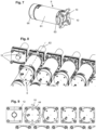
- Figure 1 shows an isometric view from the user's side from behind of two rows of a total of ten impact cylinder arrangements per row on a flue gas duct to form an impact cylinder structure.
- Figure 2 shows the view of the impact cylinder arrangements mounted on the flue gas duct from the side of the flue gas duct with the wall removed, to which the impact cylinder arrangements are welded to form the impact cylinder structure.
- Each impact cylinder arrangement includes an impact cylinder 2, which is screwed to a holding flange 4 with its front end.
- the holding flange 4 has a hollow cylindrical receiving tube, which is attached to the boiler wall with its front end.
- Each impact cylinder 2 comprises a hollow cylindrical piston jacket, which extends in the longitudinal direction along an impact cylinder longitudinal axis and is closed with an impact cylinder front plate at an impact cylinder front end, which faces the holding flange in the installed position.
- the rear end of the piston jacket facing the user is closed by a likewise circular impact cylinder rear plate.
- the radial outer diameters of the impact cylinder front plate 23 and the impact cylinder rear plate correspond to the outer diameter of the piston skirt.
- the impact cylinder front plate and Impact cylinder rear plate therefore includes a piston chamber within the piston jacket, in which a piston moves along the longitudinal axis of the impact cylinder and strikes a firing pin that is accommodated in a relatively movable manner in the impact cylinder front plate when the impact is triggered.
- the piston is therefore relatively movable within the piston chamber along the longitudinal axis of the impact cylinder between a front impact position and a rear rest position.
- Compressed air is supplied to the impact cylinder 2 via a connection and a valve accommodated within the impact cylinder regulates the alternating filling of a compressed air reservoir and an impact triggering, in which the air contained in the compressed air reservoir suddenly escapes into the piston chamber and drives the piston forward against the in to trigger the impact
- the firing pin is accommodated in a relatively moving manner on the front plate of the striking cylinder.
- each impact cylinder front plate four threaded bolts are arranged around the longitudinal axis of the impact cylinder and extend parallel to the longitudinal axis of the impact cylinder, which in the installed position sit in corresponding through holes on the plate-shaped holding flange 4 and on which in the Figure 2 Visible back of the holding flange are mounted on the holding flange 4 with four self-locking nuts.
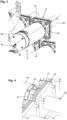
- FIG 3 shows, however, an enlarged view of an impact cylinder arrangement according to the invention, also comprising an impact cylinder 6 and a holding flange 8 attached to a support body, not shown
- Impact cylinder 6 in turn has a piston jacket 61, which extends along a longitudinal axis of impact cylinder 62 and is enclosed on the front by an impact cylinder front plate 63 and on the rear by an impact cylinder rear plate 64, which therefore close the piston space enclosed by the piston jacket 61 on the front and back.
- the impact cylinder front plate 63 and impact cylinder rear plate 64 in turn correspond in their outer diameter to the outer diameter of the piston jacket 61, so that a continuous cylindrical body is formed, which is screwed to the holding flange at the front and to which compressed air can be supplied at the rear via a connection 65.
- the holding flange 8 comprises a holding flange plate 81, on the front of which a hollow cylindrical guide sleeve 82 is welded in the middle and extends from the plane defined by the holding flange plate 81 forward to the carrier body and is connected to it.
- the anvil which is accommodated in the impact cylinder 6 in a relatively movable manner, strikes a plunger which is accommodated in a longitudinally displaceable manner in the guide sleeve 82 when struck by the impact cylinder front plate 63, which in turn impacts the support body.
- the exact structure is not the subject of the invention, but the holding flange plate 81 and the connection plate 10 are formed in the middle with corresponding central openings 84 so that the plunger can extend through these two components in the installed position.
- the isometric enlarged top view of the impact cylinder arrangement according to Figure 4 shows how these cylinder head screws 2 are screwed through the connection plate 10 into the holding flange plate 81 and thus fix the connection plate 10 flat on the holding flange plate 81 of the holding flange 8.
- Figure 5 shows the holding flange 8 geometrically adapted to the holding plate 10 in an isometric view from above.
- This is also designed as a square metal plate, in particular a steel plate, adapted to the size of the connection plate 10, which is provided in the four corners with threaded openings 83 or extending transversely to the connection plate, i.e. with holes in which there is an internal thread corresponding to the screws is provided.
- the four cylinder head screws 12 can be screwed into these internal threads, each of which has a cylindrical screw shaft with an external thread and, at a rear end, a cylindrical screw head with an Allen key that is significantly wider than this screw shaft.
- connection plate 10 can be screwed onto the impact cylinder front plate 63 using four screws, in particular countersunk screws.
- the spacers and tappets are installed.
- three cylinder head screws 12 are screwed in, preferably the two upper ones and one lower one.
- the cylinder head screws 12 are only screwed in so far that they hold securely and do not fall out.
- the screw head distance to the spacer is preferably more than 20 mm, i.e. more than the thickness of the connection plate 10.
- the last cylinder head screw 12 at the bottom right is intentionally not installed yet.
- connection plate 10 has the semicircular or arcuate screw-in guides 13 at the appropriate points.
- the impact cylinder 6 is rotated 45° to the left around the longitudinal axis 62 of the impact cylinder.
- the three arcuate screw-in guides 13 (circular elongated holes) are now pushed over the screw shafts, whereby the impact cylinder 6 hooks into place. Now the fitter can release the impact cylinder 6, since the screw heads with a larger outer diameter than the screw-in guides 13 effectively prevent slipping.
- the fourth cylinder head screw 12 is screwed in. This alone prevents the impact cylinder 6 from being turned back and thus loosened. This only needs to be installed hand-tight.
- the time that the impact cylinder 6 has to be held in the hands is minimal compared to the prior art.
- the cylinder head screws 12 only need to be turned slightly by hand. After the first rotation, the respective cylinder head screw 12 and the impact cylinder 6 are secured against falling.
- a cordless screwdriver with standard tools can fasten the screws more quickly compared to the state of the art.
- Figure 10 shows a front view of the connection plate 10.
- This therefore comprises a central area, which is designed as a connecting section for connection to the impact cylinder front plate 63 and has a flat contact area with a central through hole for the firing pin and a lowering area arranged around the screw holes 11 is used the fastening screw for mounting the connection plate 10 on the impact cylinder front plate 63.
- the central connecting section is circumferentially enclosed by the fastening section, which in the present embodiment is designed as a square connection plate 10 with equal side lengths, the side length of the connection plate 10 being approximately 5 to 20 Percent larger than the diameter of the impact cylinder 6, in order to provide a sufficient projection area for the fastening section when the impact cylinder 6 is screwed with its impact cylinder front plate 63 to the connection plate 10.
- the connection plate 10 in the installed position, the connection plate 10 preferably has a fastening section which circumferentially encloses the outer lateral surface of the impact cylinder front plate 63 in the installed position and which has an associated through hole 11 in each corner.
- the right, lower through hole 11 is designed solely as a cylindrical through hole.
- the through holes 11 are formed with an arcuate screw-in guides 13 which extend laterally therefrom and run to the adjacent side i.e. extends from approximately the middle of an adjacent side of the connection plate 10 into the through holes 11, so that an elongated hole ending in the through hole 11 is formed.
- This configuration is provided at three corners of the connection plate 10, namely at the ones in the Figure 10 both top corners and the bottom left corner.
- a center opening 14 can be provided in the middle of the connecting section for the passage of the firing pin.
- the invention relates to an impact cylinder holding arrangement with an impact cylinder 6 which can be fastened to a holding flange 8 by means of bolts.
- the bolts are designed as screws and a fastening section which projects radially beyond the outer peripheral region of an impact cylinder front plate 63 is provided and which has a fastening plane for abutment against the retaining flange 8 Installation position forms and has at least two diametrically opposite through holes 11, which extend transversely to the fastening plane and are designed for inserting the screw shaft of the screws.
- the holding flange 8 is designed for screwing in the screws.
Landscapes
- Engineering & Computer Science (AREA)
- General Engineering & Computer Science (AREA)
- Mechanical Engineering (AREA)
- Chemical & Material Sciences (AREA)
- Combustion & Propulsion (AREA)
- Percussive Tools And Related Accessories (AREA)
- Earth Drilling (AREA)
- Portable Nailing Machines And Staplers (AREA)
Claims (8)
- Ensemble de maintien de cylindre de percussion comprenantun cylindre de percussion (6) présentantune plaque de cylindre de percussion (63) avant disposée à une extrémité avant,une enveloppe de piston (61) cylindrique qui s'étend de l'extrémité avant à une extrémité arrière et qui entoure circonférentiellement une chambre à piston intérieure,une plaque de cylindre de percussion (64) arrière refermant la chambre à piston à l'extrémité arrière,un piston disposé dans la chambre à piston et mobile longitudinalement le long d'un axe longitudinal entre une position de percussion avant et une position de repos arrière,un percuteur, une barre de percussion, une enclume ou similaire, logé(e) de façon mobile dans la plaque de cylindre de percussion (63) avant,un raccord (65) d'alimentation en fluide, en particulier en air comprimé,ainsi qu'une valve destinée à sélectivement remplir un réservoir d'air comprimé et actionner le piston pour le déclenchement d'une percussion,des boulons étant prévus à l'extrémité avant du cylindre de percussion pour la fixation à une bride de maintien (8) reliée à un corps de support, en particulier à une chaudière ou similaire,les boulons étant réalisés sous forme de vis qui présentent une tige de vis, pourvue d'un filet de vis, et une tête de vis ayant un diamètre de tête de vis agrandi par rapport au filet de vis,caractérisé en ce quesur la plaque de cylindre de percussion (63) avant ou sur une plaque de raccordement (10) susceptible d'être reliée à celle-ci, il est prévu une partie de fixation dépassant radialement d'une zone périphérique extérieure de la plaque de cylindre de percussion (63) avant pour former une partie de fixation en forme de bride, qui constitue un plan de fixation pour l'appui contre la bride de maintien (8),en ce qu'au moins deux trous de passage (11) diamétralement opposés sont ménagés dans la partie de fixation, qui s'étendent transversalement au plan de fixation et qui sont conçus pour le passage de la tige des vis,en ce que les trous de passage (11) présentent des guides de vissage (13) débouchant latéralement dans ceux-ci, eten ce que la bride de maintien (8) comprend des trous taraudés pour le vissage des vis.
- Ensemble de maintien de cylindre à percussion selon la revendication 1, caractérisé en ce que
la partie de fixation est réalisée d'une seule pièce sur la plaque de cylindre de percussion (63) avant. - Ensemble de maintien de cylindre de percussion selon la revendication 1, caractérisé en ce que
la partie de fixation est réalisée sur une plaque de raccordement (10) qui peut être raccordée ou est raccordée à la plaque de cylindre de percussion (63) avant. - Ensemble de maintien de cylindre de percussion selon l'une des revendications précédentes,
caractérisé en ce que
la partie de fixation est réalisée sous forme de bord de fixation ou de bride de fixation continu(e) qui, à l'extrémité avant du cylindre de percussion, s'étend radialement sur la surface enveloppe extérieure du cylindre de percussion (6) et la plaque de cylindre de percussion (63) avant. - Ensemble de maintien de cylindre de percussion selon l'une des revendications précédentes,
caractérisé en ce que
la partie de fixation présente au moins deux zones de fixation diamétralement opposées, s'étendant séparément sur la surface de projection du cylindre de percussion, en vue frontale, qui dépassent radialement au-delà de la surface enveloppe du cylindre de percussion. - Ensemble de maintien de cylindre de percussion selon l'une des revendications précédentes,
caractérisé en ce que
les vis sont réalisées sous forme de vis à tête cylindrique (12). - Ensemble de maintien de cylindre de percussion selon l'une des revendications précédentes,
caractérisé en ce que
la bride de maintien (8) présente des trous taraudés (83) qui sont complémentaires aux vis. - Procédé de montage et/ou de maintenance pour la fixation amovible d'un cylindre de percussion (6) sur une bride de maintien (8) d'un corps de support au moyen de vis,
caractérisé en ce quela bride de maintien (8) présente des trous taraudés (83) complémentaires aux vis,en ce que sur une plaque de cylindre de percussion (63) avant ou sur une plaque de raccordement (10) reliée ou pouvant être reliée à celle-ci, il est prévu une partie de fixation en forme de bride (bride de fixation) dépassant radialement d'une zone périphérique extérieure de la plaque de cylindre de percussion (63) avant, qui forme un plan de fixation pour l'appui contre la bride de maintien (8) et qui présente au moins deux trous de passage (11) diamétralement opposés, qui s'étendent transversalement au plan de fixation et sont conçus pour le passage d'une tige des vis,en ce qu'au moins deux des trous de passage (11) présentent des guides de vissage (13) débouchant latéralement dans ceux-ci,en ce que les vis sont d'abord vissées ou desserrées dans des trous taraudés (83) correspondants de la bride de maintien (8),en ce que le cylindre de percussion (6) est ensuite saisi ou appliqué,en ce que le cylindre de percussion (6) est ensuite tourné dans un sens de fixation ou dans un sens de desserrage,et en ce que les vis sont finalement serrées pour la fixation finale, ou le cylindre de percussion (6) est retiré et un autre cylindre de percussion est mis en place.
Applications Claiming Priority (2)
| Application Number | Priority Date | Filing Date | Title |
|---|---|---|---|
| DE102020134265.9A DE102020134265A1 (de) | 2020-12-18 | 2020-12-18 | Schlagzylinderhalteanordnung umfassend einen Schlagzylinder und einen mit einem Trägerkörper verbundener Halteflansch |
| PCT/EP2021/085427 WO2022128883A1 (fr) | 2020-12-18 | 2021-12-13 | Ensemble de maintien de cylindre d'impact comprenant un cylindre d'impact et une bride de maintien reliée à un corps de support |
Publications (3)
| Publication Number | Publication Date |
|---|---|
| EP4200552A1 EP4200552A1 (fr) | 2023-06-28 |
| EP4200552B1 true EP4200552B1 (fr) | 2023-11-29 |
| EP4200552C0 EP4200552C0 (fr) | 2023-11-29 |
Family
ID=79283082
Family Applications (1)
| Application Number | Title | Priority Date | Filing Date |
|---|---|---|---|
| EP21839383.3A Active EP4200552B1 (fr) | 2020-12-18 | 2021-12-13 | Ensemble de maintien de cylindre d'impact comprenant un cylindre d'impact et une bride de maintien reliée à un corps de support |
Country Status (3)
| Country | Link |
|---|---|
| EP (1) | EP4200552B1 (fr) |
| DE (1) | DE102020134265A1 (fr) |
| WO (1) | WO2022128883A1 (fr) |
Family Cites Families (8)
| Publication number | Priority date | Publication date | Assignee | Title |
|---|---|---|---|---|
| US2973233A (en) * | 1958-10-02 | 1961-02-28 | John E Mcphee | Disengageable leg assembly |
| DE3324456A1 (de) | 1983-07-07 | 1985-01-17 | Tenge-Rietberg, Carl Friedrich, 4835 Rietberg | Wandseitig zu befestigender klappsitz |
| DE3334456C2 (de) | 1983-09-23 | 1986-06-12 | L. & C. Steinmüller GmbH, 5270 Gummersbach | Vorrichtung zur Kraftstoßübertragung |
| DE29512786U1 (de) * | 1995-08-09 | 1995-10-12 | Judo Wasseraufbereitung GmbH, 71364 Winnenden | Anschlußstück |
| DE19851268C1 (de) * | 1998-11-06 | 1999-08-26 | Wolf Gmbh Richard | Einrichtung zur lösbaren Verbindung zweier zusammensteckbarer Bauteile, insbesondere zur Verbindung von Bauteilen medizinischer Geräte, Apparate und Instrumente |
| CN201596660U (zh) | 2008-12-02 | 2010-10-06 | 国际壳牌研究有限公司 | 振打装置 |
| DE102009051089B4 (de) * | 2009-10-28 | 2017-12-07 | Rosink-Werkstätten GmbH | Schlagzylinder |
| FI122923B (sv) | 2010-11-23 | 2012-08-31 | Kamwest Oy | Slaganordning för rengöring av ytor, speciellt värmeytor |
-
2020
- 2020-12-18 DE DE102020134265.9A patent/DE102020134265A1/de not_active Ceased
-
2021
- 2021-12-13 EP EP21839383.3A patent/EP4200552B1/fr active Active
- 2021-12-13 WO PCT/EP2021/085427 patent/WO2022128883A1/fr not_active Ceased
Also Published As
| Publication number | Publication date |
|---|---|
| WO2022128883A1 (fr) | 2022-06-23 |
| EP4200552A1 (fr) | 2023-06-28 |
| EP4200552C0 (fr) | 2023-11-29 |
| DE102020134265A1 (de) | 2022-06-23 |
Similar Documents
| Publication | Publication Date | Title |
|---|---|---|
| DE102010012748B4 (de) | Kettensäge | |
| EP0458069A1 (fr) | Liaison transversale pour des barres profilées | |
| EP3399120B1 (fr) | Système de coffrage à ancre comprenant deux éléments de coffrage éloignés l'un de l'autre, son procédé de montage | |
| WO2016026812A1 (fr) | Dispositif d'ancrage d'un coffrage pour mur en béton, élément de coffrage et procédé de montage d'un dispositif d'ancrage | |
| DE202004014423U1 (de) | Vorrichtung zur Montage einer Kfz.-Kupplung | |
| EP3658785B1 (fr) | Boulon d'écartement et ensemble de liaison comportant un tel boulon d'écartement | |
| EP0475216B1 (fr) | Dispositif d'assemblage entre des poutres et des noeuds d'une structure tridimensionelle | |
| EP4130495B1 (fr) | Système de fixation destiné à la fixation d'une pièce rapportée et procédé de fixation et d'ajustement de la pièce rapportée | |
| DE19715496C1 (de) | Justierelement | |
| DE2618877B2 (de) | Vorrichtung zum Kontern und Brechen der Gewindeverbindungen zwischen Rohrkörpern | |
| EP3909903B1 (fr) | Point de butée | |
| EP1143182A2 (fr) | Vis et raccord à vis entre un tuyau flexible et une conduite de freins | |
| EP4200552A1 (fr) | Ensemble de maintien de cylindre d'impact comprenant un cylindre d'impact et une bride de maintien reliée à un corps de support | |
| DE102004051059B4 (de) | Vorrichtung zur Montage einer Ölspritzdüse | |
| DE3111764C2 (fr) | ||
| DE202005019595U1 (de) | Vorrichtung zum Ausziehen von Einspritzdüsen | |
| DE102011115627B4 (de) | Spreizvorrichtung | |
| DE202009008994U1 (de) | Gerüstkonstruktion | |
| DE10221773B4 (de) | Griff mit mindestens einem Halsteil und mit einer Befestigungsvorrichtung je Halsteil | |
| DE69400049T2 (de) | Vorrichtung zur Montage von Verbindungsbolzen für Gerüsteelemente und Verbindungsbolzen hierfür | |
| DE8814967U1 (de) | Schraubenschlüssel für Flügelmuttern von Schraubspindeln des Betonsbaus | |
| DE102006058764B4 (de) | Befestigungsvorrichtung für den Anbau von Rollenbaueinheiten am Fahrgestell von Transportwagen oder dergleichen | |
| DE102010042581B4 (de) | Werkzeug zur Montage und Demontage eines Injektors einer Brennkraftmaschine | |
| DE102022000879A1 (de) | Einhänge- und Verspannvorrichtung von Klettergriffen | |
| DE102014209668B4 (de) | Werkzeug zur Demontage eines Injektors einer Brennkraftmaschine |
Legal Events
| Date | Code | Title | Description |
|---|---|---|---|
| STAA | Information on the status of an ep patent application or granted ep patent |
Free format text: STATUS: UNKNOWN |
|
| STAA | Information on the status of an ep patent application or granted ep patent |
Free format text: STATUS: THE INTERNATIONAL PUBLICATION HAS BEEN MADE |
|
| PUAI | Public reference made under article 153(3) epc to a published international application that has entered the european phase |
Free format text: ORIGINAL CODE: 0009012 |
|
| STAA | Information on the status of an ep patent application or granted ep patent |
Free format text: STATUS: REQUEST FOR EXAMINATION WAS MADE |
|
| 17P | Request for examination filed |
Effective date: 20230319 |
|
| AK | Designated contracting states |
Kind code of ref document: A1 Designated state(s): AL AT BE BG CH CY CZ DE DK EE ES FI FR GB GR HR HU IE IS IT LI LT LU LV MC MK MT NL NO PL PT RO RS SE SI SK SM TR |
|
| GRAP | Despatch of communication of intention to grant a patent |
Free format text: ORIGINAL CODE: EPIDOSNIGR1 |
|
| STAA | Information on the status of an ep patent application or granted ep patent |
Free format text: STATUS: GRANT OF PATENT IS INTENDED |
|
| INTG | Intention to grant announced |
Effective date: 20230727 |
|
| GRAS | Grant fee paid |
Free format text: ORIGINAL CODE: EPIDOSNIGR3 |
|
| GRAA | (expected) grant |
Free format text: ORIGINAL CODE: 0009210 |
|
| STAA | Information on the status of an ep patent application or granted ep patent |
Free format text: STATUS: THE PATENT HAS BEEN GRANTED |
|
| DAV | Request for validation of the european patent (deleted) | ||
| DAX | Request for extension of the european patent (deleted) | ||
| AK | Designated contracting states |
Kind code of ref document: B1 Designated state(s): AL AT BE BG CH CY CZ DE DK EE ES FI FR GB GR HR HU IE IS IT LI LT LU LV MC MK MT NL NO PL PT RO RS SE SI SK SM TR |
|
| REG | Reference to a national code |
Ref country code: GB Ref legal event code: FG4D Free format text: NOT ENGLISH |
|
| REG | Reference to a national code |
Ref country code: CH Ref legal event code: EP |
|
| REG | Reference to a national code |
Ref country code: DE Ref legal event code: R096 Ref document number: 502021002097 Country of ref document: DE |
|
| REG | Reference to a national code |
Ref country code: IE Ref legal event code: FG4D Free format text: LANGUAGE OF EP DOCUMENT: GERMAN |
|
| U01 | Request for unitary effect filed |
Effective date: 20231228 |
|
| U07 | Unitary effect registered |
Designated state(s): AT BE BG DE DK EE FI FR IT LT LU LV MT NL PT SE SI Effective date: 20240109 |
|
| U20 | Renewal fee for the european patent with unitary effect paid |
Year of fee payment: 3 Effective date: 20240126 |
|
| PG25 | Lapsed in a contracting state [announced via postgrant information from national office to epo] |
Ref country code: GR Free format text: LAPSE BECAUSE OF FAILURE TO SUBMIT A TRANSLATION OF THE DESCRIPTION OR TO PAY THE FEE WITHIN THE PRESCRIBED TIME-LIMIT Effective date: 20240301 |
|
| PG25 | Lapsed in a contracting state [announced via postgrant information from national office to epo] |
Ref country code: IS Free format text: LAPSE BECAUSE OF FAILURE TO SUBMIT A TRANSLATION OF THE DESCRIPTION OR TO PAY THE FEE WITHIN THE PRESCRIBED TIME-LIMIT Effective date: 20240329 |
|
| PG25 | Lapsed in a contracting state [announced via postgrant information from national office to epo] |
Ref country code: ES Free format text: LAPSE BECAUSE OF FAILURE TO SUBMIT A TRANSLATION OF THE DESCRIPTION OR TO PAY THE FEE WITHIN THE PRESCRIBED TIME-LIMIT Effective date: 20231129 |
|
| PG25 | Lapsed in a contracting state [announced via postgrant information from national office to epo] |
Ref country code: IS Free format text: LAPSE BECAUSE OF FAILURE TO SUBMIT A TRANSLATION OF THE DESCRIPTION OR TO PAY THE FEE WITHIN THE PRESCRIBED TIME-LIMIT Effective date: 20240329 Ref country code: GR Free format text: LAPSE BECAUSE OF FAILURE TO SUBMIT A TRANSLATION OF THE DESCRIPTION OR TO PAY THE FEE WITHIN THE PRESCRIBED TIME-LIMIT Effective date: 20240301 Ref country code: ES Free format text: LAPSE BECAUSE OF FAILURE TO SUBMIT A TRANSLATION OF THE DESCRIPTION OR TO PAY THE FEE WITHIN THE PRESCRIBED TIME-LIMIT Effective date: 20231129 |
|
| PG25 | Lapsed in a contracting state [announced via postgrant information from national office to epo] |
Ref country code: RS Free format text: LAPSE BECAUSE OF FAILURE TO SUBMIT A TRANSLATION OF THE DESCRIPTION OR TO PAY THE FEE WITHIN THE PRESCRIBED TIME-LIMIT Effective date: 20231129 Ref country code: PL Free format text: LAPSE BECAUSE OF FAILURE TO SUBMIT A TRANSLATION OF THE DESCRIPTION OR TO PAY THE FEE WITHIN THE PRESCRIBED TIME-LIMIT Effective date: 20231129 Ref country code: NO Free format text: LAPSE BECAUSE OF FAILURE TO SUBMIT A TRANSLATION OF THE DESCRIPTION OR TO PAY THE FEE WITHIN THE PRESCRIBED TIME-LIMIT Effective date: 20240229 Ref country code: HR Free format text: LAPSE BECAUSE OF FAILURE TO SUBMIT A TRANSLATION OF THE DESCRIPTION OR TO PAY THE FEE WITHIN THE PRESCRIBED TIME-LIMIT Effective date: 20231129 |
|
| PG25 | Lapsed in a contracting state [announced via postgrant information from national office to epo] |
Ref country code: CZ Free format text: LAPSE BECAUSE OF FAILURE TO SUBMIT A TRANSLATION OF THE DESCRIPTION OR TO PAY THE FEE WITHIN THE PRESCRIBED TIME-LIMIT Effective date: 20231129 |
|
| PG25 | Lapsed in a contracting state [announced via postgrant information from national office to epo] |
Ref country code: SK Free format text: LAPSE BECAUSE OF FAILURE TO SUBMIT A TRANSLATION OF THE DESCRIPTION OR TO PAY THE FEE WITHIN THE PRESCRIBED TIME-LIMIT Effective date: 20231129 |
|
| PG25 | Lapsed in a contracting state [announced via postgrant information from national office to epo] |
Ref country code: SM Free format text: LAPSE BECAUSE OF FAILURE TO SUBMIT A TRANSLATION OF THE DESCRIPTION OR TO PAY THE FEE WITHIN THE PRESCRIBED TIME-LIMIT Effective date: 20231129 Ref country code: SK Free format text: LAPSE BECAUSE OF FAILURE TO SUBMIT A TRANSLATION OF THE DESCRIPTION OR TO PAY THE FEE WITHIN THE PRESCRIBED TIME-LIMIT Effective date: 20231129 Ref country code: RO Free format text: LAPSE BECAUSE OF FAILURE TO SUBMIT A TRANSLATION OF THE DESCRIPTION OR TO PAY THE FEE WITHIN THE PRESCRIBED TIME-LIMIT Effective date: 20231129 Ref country code: CZ Free format text: LAPSE BECAUSE OF FAILURE TO SUBMIT A TRANSLATION OF THE DESCRIPTION OR TO PAY THE FEE WITHIN THE PRESCRIBED TIME-LIMIT Effective date: 20231129 |
|
| PG25 | Lapsed in a contracting state [announced via postgrant information from national office to epo] |
Ref country code: MC Free format text: LAPSE BECAUSE OF FAILURE TO SUBMIT A TRANSLATION OF THE DESCRIPTION OR TO PAY THE FEE WITHIN THE PRESCRIBED TIME-LIMIT Effective date: 20231129 |
|
| PG25 | Lapsed in a contracting state [announced via postgrant information from national office to epo] |
Ref country code: MC Free format text: LAPSE BECAUSE OF FAILURE TO SUBMIT A TRANSLATION OF THE DESCRIPTION OR TO PAY THE FEE WITHIN THE PRESCRIBED TIME-LIMIT Effective date: 20231129 |
|
| REG | Reference to a national code |
Ref country code: DE Ref legal event code: R097 Ref document number: 502021002097 Country of ref document: DE |
|
| PLBE | No opposition filed within time limit |
Free format text: ORIGINAL CODE: 0009261 |
|
| STAA | Information on the status of an ep patent application or granted ep patent |
Free format text: STATUS: NO OPPOSITION FILED WITHIN TIME LIMIT |
|
| REG | Reference to a national code |
Ref country code: IE Ref legal event code: MM4A |
|
| PG25 | Lapsed in a contracting state [announced via postgrant information from national office to epo] |
Ref country code: IE Free format text: LAPSE BECAUSE OF NON-PAYMENT OF DUE FEES Effective date: 20231213 |
|
| PG25 | Lapsed in a contracting state [announced via postgrant information from national office to epo] |
Ref country code: IE Free format text: LAPSE BECAUSE OF NON-PAYMENT OF DUE FEES Effective date: 20231213 |
|
| 26N | No opposition filed |
Effective date: 20240830 |
|
| U20 | Renewal fee for the european patent with unitary effect paid |
Year of fee payment: 4 Effective date: 20241223 |
|
| PG25 | Lapsed in a contracting state [announced via postgrant information from national office to epo] |
Ref country code: CY Free format text: LAPSE BECAUSE OF FAILURE TO SUBMIT A TRANSLATION OF THE DESCRIPTION OR TO PAY THE FEE WITHIN THE PRESCRIBED TIME-LIMIT; INVALID AB INITIO Effective date: 20211213 |
|
| REG | Reference to a national code |
Ref country code: CH Ref legal event code: PL |
|
| PG25 | Lapsed in a contracting state [announced via postgrant information from national office to epo] |
Ref country code: CH Free format text: LAPSE BECAUSE OF NON-PAYMENT OF DUE FEES Effective date: 20241231 |
|
| PG25 | Lapsed in a contracting state [announced via postgrant information from national office to epo] |
Ref country code: TR Free format text: LAPSE BECAUSE OF FAILURE TO SUBMIT A TRANSLATION OF THE DESCRIPTION OR TO PAY THE FEE WITHIN THE PRESCRIBED TIME-LIMIT Effective date: 20231129 |
|
| U20 | Renewal fee for the european patent with unitary effect paid |
Year of fee payment: 5 Effective date: 20251216 |
|
| PG25 | Lapsed in a contracting state [announced via postgrant information from national office to epo] |
Ref country code: HU Free format text: LAPSE BECAUSE OF FAILURE TO SUBMIT A TRANSLATION OF THE DESCRIPTION OR TO PAY THE FEE WITHIN THE PRESCRIBED TIME-LIMIT; INVALID AB INITIO Effective date: 20211213 |
|
| PG25 | Lapsed in a contracting state [announced via postgrant information from national office to epo] |
Ref country code: CH Free format text: THE PATENT HAS BEEN ANNULLED BY A DECISION OF A NATIONAL AUTHORITY Effective date: 20241231 |