EP4200508B1 - Vorrichtung und verfahren zum reinigen einer bohrlochöffnung - Google Patents
Vorrichtung und verfahren zum reinigen einer bohrlochöffnung Download PDFInfo
- Publication number
- EP4200508B1 EP4200508B1 EP21759429.0A EP21759429A EP4200508B1 EP 4200508 B1 EP4200508 B1 EP 4200508B1 EP 21759429 A EP21759429 A EP 21759429A EP 4200508 B1 EP4200508 B1 EP 4200508B1
- Authority
- EP
- European Patent Office
- Prior art keywords
- boom
- sweeper assembly
- borehole
- brush
- entrance
- Prior art date
- Legal status (The legal status is an assumption and is not a legal conclusion. Google has not performed a legal analysis and makes no representation as to the accuracy of the status listed.)
- Active
Links
Images


Classifications
-
- E—FIXED CONSTRUCTIONS
- E21—EARTH OR ROCK DRILLING; MINING
- E21B—EARTH OR ROCK DRILLING; OBTAINING OIL, GAS, WATER, SOLUBLE OR MELTABLE MATERIALS OR A SLURRY OF MINERALS FROM WELLS
- E21B12/00—Accessories for drilling tools
- E21B12/06—Mechanical cleaning devices
-
- E—FIXED CONSTRUCTIONS
- E21—EARTH OR ROCK DRILLING; MINING
- E21B—EARTH OR ROCK DRILLING; OBTAINING OIL, GAS, WATER, SOLUBLE OR MELTABLE MATERIALS OR A SLURRY OF MINERALS FROM WELLS
- E21B37/00—Methods or apparatus for cleaning boreholes or wells
- E21B37/02—Scrapers specially adapted therefor
-
- A—HUMAN NECESSITIES
- A46—BRUSHWARE
- A46B—BRUSHES
- A46B13/00—Brushes with driven brush bodies or carriers
-
- B—PERFORMING OPERATIONS; TRANSPORTING
- B08—CLEANING
- B08B—CLEANING IN GENERAL; PREVENTION OF FOULING IN GENERAL
- B08B1/00—Cleaning by methods involving the use of tools
- B08B1/10—Cleaning by methods involving the use of tools characterised by the type of cleaning tool
- B08B1/12—Brushes
-
- B—PERFORMING OPERATIONS; TRANSPORTING
- B08—CLEANING
- B08B—CLEANING IN GENERAL; PREVENTION OF FOULING IN GENERAL
- B08B1/00—Cleaning by methods involving the use of tools
- B08B1/10—Cleaning by methods involving the use of tools characterised by the type of cleaning tool
- B08B1/16—Rigid blades, e.g. scrapers; Flexible blades, e.g. wipers
- B08B1/165—Scrapers
Definitions
- the present disclosure relates to a sweeper assembly arranged at a distal end of a boom of a mining or construction work machine.
- the sweeper assembly may be used for preparing boreholes for a blasting operation.
- the present disclosure further relates to a method of using the sweeper assembly for removing blockages from a borehole opening.
- Mining operations and construction work commonly utilize drilling and blasting techniques. Usually, a plurality of boreholes need to be drilled into a rock surface. The boreholes extend a proper depth into the rock and are filled with explosive charges when drilling of all the holes is complete.
- drill cuttings need to be removed from the drilled holes with the aid of a flushing medium such as compressed air or liquid.
- the liquid flush medium such as water may mix with the drill cuttings to form a clay paste.
- the drill cuttings from a hole currently being drilled can block entrance to the already drilled holes nearby.
- the particularly affected are the lifter holes which are drilled along the floor of a tunnel for lifting the rock to floor level. The lifter holes may become buried and covered up completely by the drill cuttings and/or the clay paste thereof.
- US1612186 discloses a rotatable brush for removal of loose earth resting upon the blade of a boring member or an auger.
- the rotatable brush is positioned at one side of the blade and fixedly connected to the auger.
- the rotation of auger causes all portions of the auger blade upon which the loose earth rests to be presented to similarly timed rotative movement of the brush, and results in the removal of the loose earth away from the auger blade and the vicinity of the borehole in the ground.
- the brush is inappropriate for cleaning a lifter hole buried and covered up by tough drill cuttings and/or clay paste thereof.
- one object of the present disclosure is therefore to reduce manual workload and risks for personnel at the site during operations for clearing a borehole opening of blockages at entrance to the borehole.
- Yet another object of the disclosure is to provide a novel and advantageous solution for clearing a borehole opening of blockages at entrance to the borehole.
- Yet another object of the disclosure is to provide a robust and reliable solution for clearing a borehole opening of blockages at entrance to the borehole.
- Yet another object of the disclosure is to improve mechanization and automation of clearing a borehole opening of blockages at entrance to the borehole.
- the sweeper assembly as was described above comprises at least one rotary actuator and/or at least one linear actuator.
- the at least one rotary actuator is used to transform energy to mechanical rotation of the sweeper assembly.
- the at least one linear actuator is used to move the sweeper assembly in a straight line.
- the sweeper assembly as was described above further comprises at least one brush configured to rotate about an axis A.
- the rotating brush has the advantage of producing a continuous cleaning of a large area thereby increasing work efficiency and productivity.
- the brush as was described above may comprise a rotatable shaft or drum.
- the rotary actuator as was described above controls mechanical rotation of the at least one brush via the shaft or drum.
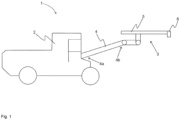
- a boom 4 of a mining or construction work machine 1 which boom 4 comprising a first end 4a connectable to the mining or construction work machine 1, a distal second end 4b, and a sweeper assembly 6 arranged at the distal second end 4b of the boom 4.
- the sweeper assembly 6 is configured to clear a borehole opening of blockages at entrance to the borehole.
- the boom 4 comprising the sweeper assembly 6 enables mechanization and automation of the process of clearing a borehole opening of blockages at entrance to the borehole. Furthermore, the sweeper assembly 6 is easy to operate.
- the at least one rotary actuator is used to transform energy to mechanical rotation of the sweeper assembly 6.
- the at least one rotary actuator may be hydraulically, pneumatically or electrically powered.
- the sweeper assembly 6 may further comprise at least one brush 7 configured to rotate about an axis A ( Figs. 2 and 3 ).
- the rotating brush 7 has the advantage of producing a continuous cleaning of a large area thereby increasing work efficiency and productivity.
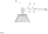
- connection means 20 comprising an extendable first part with at least two telescopic sections 51, 52 provides the advantage of space-saving storage of the brush 7 when the sweeper assembly 6 is not in use and the advantage of flexibility in getting access to the area to be swept. Operation of the extendable first part of the connection means 20 may be controlled by a linear actuator.
- the brush 7 as illustrated in Fig. 2 may comprise a rotatable shaft.
- the rotary actuator as was described above controls mechanical rotation of the at least one brush 7 via the shaft.
- the brush 7 as illustrated in Fig. 2 may comprise a single-piece mounting flange 21, wherein a plurality of single- and/or multi-strand wire packs 8 are mechanically affixed to the single-piece mounting flange 21.
- the wire packs 8 are made of wear-resistant material such as steel wires, which enables more aggressive performance of the sweeper assembly 6.
- the brush 7 as illustrated in Fig. 3 may comprise a rotatable drum 9 ( Fig. 3a).
- Fig. 3b is a cross-sectional view of the brush 7 with a rotatable drum 9.
- a cutting plane 30 indicated in Fig. 3a defines the cross-section shown in Fig. 3b .
- the rotary actuator as was described above controls mechanical rotation of the at least one brush 7 via the drum 9.
- the brush 7 as illustrated in Fig. 3 may comprise a plurality of single- and/or multi-strand wire packs 8 mechanically affixed to the drum 9.
- the wire packs 8 are made of wear-resistant material such as stainless steel, which enables aggressive performance of the sweeper assembly 6.
- the sweeper assembly 6 may comprise at least one scraping tool 10.
- the scraping tool 10 has the advantage of providing a more focused cleaning which is particularly efficient for removing tough clay paste of drill cuttings from a borehole opening.
- the sweeper assembly 6 may comprise at least one hydraulic cylinder 11 configured to control operation of the at least one scraping tool 10.
- the hydraulic cylinder 11 inherently produces linear motion of the at least one scraping tool 10.
- the sweeper assembly 6 may comprise a connection means 20, which connection means 20 comprising a shank 40 connected to the at least one scraping tool 10, a pivot member 42 connecting the shank 40 to the distal second end 4b of the boom 4, and a feeding device 41 arranged at the distal second end 4b of the boom 4, wherein the feeding device 41 is connected to the shank 40.
- the pivot member 42 enables rotary motion of the shank 40 around the pivot member 42 ( Fig. 4 ).
- a rig 1 comprising at least one boom 4 as was described above.
- the rig 1 may be a complex equipment intended for earth surface use or underground use.
- the rig 1 may be a mining or construction work machine adapted for various mining operations or construction work.
- the rig 1 may be a drilling rig adapted for drilling blasting holes, injection holes, holes for rock bolt reinforcement, etc..
- the rig 1 may be a charging rig for loading boreholes with explosive charges.
- Fig. 1 shows schematically a mining or construction work machine 1 comprising a carrier 2, at least one boom 4 and a mounting device 3 attached to the distal second end 4b of the at least one boom 4.
- the mounting device 3 comprises a beam 5 on which the sweeper assembly 6 may be arranged ( Figs. 2 and 4 ).
- Other devices or tools e.g. a drilling machine, a loading assembly as was described in our patent application SE 2030174-3 , a hose for flushing medium, an explosive delivery hose, a hose handling unit, etc. may also be arranged on the same beam 5 as the sweeper assembly 6.
- An enlarged view of the beam 5 with the sweeper assembly 6 is provided in Figs. 2 and 4 .
- the rig 1 has all the advantages that have been described above in conjunction with the boom 4 and the sweeper assembly 6.
Landscapes
- Engineering & Computer Science (AREA)
- Life Sciences & Earth Sciences (AREA)
- Geology (AREA)
- Mining & Mineral Resources (AREA)
- Physics & Mathematics (AREA)
- Environmental & Geological Engineering (AREA)
- Fluid Mechanics (AREA)
- General Life Sciences & Earth Sciences (AREA)
- Geochemistry & Mineralogy (AREA)
- Mechanical Engineering (AREA)
- Earth Drilling (AREA)
- Geophysics And Detection Of Objects (AREA)
Claims (10)
- Ausleger (4) einer Bergbau- oder Bauarbeitsmaschine (1), wobei der Ausleger (4) Folgendes umfasst:ein erstes Ende (4a), das mit der Bergbau- oder Bauarbeitsmaschine (1) verbindbar ist,ein distales zweites Ende (4b), undmindestens eine Kehranordnung (6), die an dem distalen zweiten Ende (4b) des Auslegers (4) angeordnet ist, wobei die Kehranordnung (6) dazu ausgebildet ist, Verstopfungen an einer Bohrlochöffnung am Eingang des Bohrlochs zu beseitigen, und wobei die Kehranordnung (6) mindestens ein lineares Stellglied umfasst, das dazu ausgebildet ist, die Kehranordnung (6) in einer geraden Linie zu bewegen.
- Ausleger (4) nach Anspruch 1, wobei die Kehranordnung (6) weiter mindestens ein drehendes Stellglied umfasst.
- Ausleger (4) nach Anspruch 1 oder 2, wobei die Kehranordnung (6) weiter mindestens eine Bürste (7) umfasst, die dazu ausgebildet ist, sich um eine Achse A zu drehen.
- Ausleger (4) nach Anspruch 3, wobei die Bürste (7) eine drehbare Welle umfasst.
- Ausleger (4) nach Anspruch 3, wobei die Bürste (7) eine drehbare Trommel (9) umfasst.
- Ausleger (4) nach einem der Ansprüche 3 bis 5, wobei die Bürste (7) weiter eine Vielzahl von einfach und/oder mehrfach verseilten Stahldrahtpaketen (8) umfasst.
- Ausleger (4) nach Anspruch 1 oder 2, wobei die Kehranordnung (6) mindestens ein Schabwerkzeug (10) umfasst.
- Ausleger (4) nach Anspruch 7, wobei die Kehranordnung (6) mindestens einen Hydraulikzylinder (11) umfasst, der dazu ausgebildet ist, den Betrieb des mindestens einen Schabwerkzeugs (10) zu steuern.
- Bohranlage (1), die mindestens einen Ausleger (4) nach einem der vorstehenden Ansprüche umfasst.
- Verfahren zum Beseitigen von Verstopfungen von einer Bohrlochöffnung am Eingang des Bohrlochs, wobei das Verfahren die Schritte umfasst zum Positionieren der Kehranordnung (6) nach einem der Ansprüche 1 bis 8 am Eingang des Bohrlochs; und
Steuern des Betriebs der Kehranordnung (6), um Verstopfungen von der Bohrlochöffnung zu entfernen.
Applications Claiming Priority (2)
| Application Number | Priority Date | Filing Date | Title |
|---|---|---|---|
| SE2050959A SE544331C2 (en) | 2020-08-18 | 2020-08-18 | Apparatus and method for clearing a borehole opening |
| PCT/SE2021/050801 WO2022039653A1 (en) | 2020-08-18 | 2021-08-17 | Apparatus and method for clearing a borehole opening |
Publications (3)
| Publication Number | Publication Date |
|---|---|
| EP4200508A1 EP4200508A1 (de) | 2023-06-28 |
| EP4200508B1 true EP4200508B1 (de) | 2025-03-19 |
| EP4200508C0 EP4200508C0 (de) | 2025-03-19 |
Family
ID=77499891
Family Applications (1)
| Application Number | Title | Priority Date | Filing Date |
|---|---|---|---|
| EP21759429.0A Active EP4200508B1 (de) | 2020-08-18 | 2021-08-17 | Vorrichtung und verfahren zum reinigen einer bohrlochöffnung |
Country Status (5)
| Country | Link |
|---|---|
| EP (1) | EP4200508B1 (de) |
| AU (1) | AU2021327697A1 (de) |
| CA (1) | CA3188347A1 (de) |
| SE (1) | SE544331C2 (de) |
| WO (1) | WO2022039653A1 (de) |
Family Cites Families (7)
| Publication number | Priority date | Publication date | Assignee | Title |
|---|---|---|---|---|
| US1612186A (en) * | 1926-12-28 | Posthole digger | ||
| DE4330973A1 (de) * | 1992-10-02 | 1994-04-07 | Putzmeister Maschf | Bürstenkopf für Großmanipulatoren |
| US6527345B2 (en) | 2001-05-10 | 2003-03-04 | Inco Limited | Method for excavating a tunnel rock face by drilling a pattern of lifter and line holes |
| KR100893316B1 (ko) * | 2008-12-11 | 2009-04-15 | 주식회사 고속도로관리공단 | 터널 조명등 세척기 |
| SE536651C2 (sv) | 2010-11-17 | 2014-04-29 | Atlas Copco Rock Drills Ab | Förfarande, system och bergborrningssystem för installationav rör vid bergborrning |
| CN109372534A (zh) * | 2018-11-15 | 2019-02-22 | 江西蓝翔重工有限公司 | 一种运输槽体上带电缆卷筒的钻装机组 |
| CN210396627U (zh) * | 2019-09-02 | 2020-04-24 | 无锡中维建筑机械制造有限公司 | 一种用于滑移装载机的液压螺旋钻 |
-
2020
- 2020-08-18 SE SE2050959A patent/SE544331C2/en unknown
-
2021
- 2021-08-17 WO PCT/SE2021/050801 patent/WO2022039653A1/en not_active Ceased
- 2021-08-17 EP EP21759429.0A patent/EP4200508B1/de active Active
- 2021-08-17 CA CA3188347A patent/CA3188347A1/en active Pending
- 2021-08-17 AU AU2021327697A patent/AU2021327697A1/en active Pending
Also Published As
| Publication number | Publication date |
|---|---|
| SE2050959A1 (en) | 2022-02-19 |
| WO2022039653A1 (en) | 2022-02-24 |
| EP4200508C0 (de) | 2025-03-19 |
| EP4200508A1 (de) | 2023-06-28 |
| AU2021327697A1 (en) | 2023-02-09 |
| CA3188347A1 (en) | 2022-02-24 |
| SE544331C2 (en) | 2022-04-12 |
Similar Documents
| Publication | Publication Date | Title |
|---|---|---|
| CN111684144B (zh) | 移动式地下隧道掘进机装置 | |
| US3729056A (en) | Mining and excavating apparatus | |
| CN106761792A (zh) | 一种全套管全回转钻机套筒及盾构刀盘前方障碍物清除方法 | |
| JP6685214B2 (ja) | トンネル掘削方法及びトンネル掘削機 | |
| JP7598869B2 (ja) | 地中にパイプを設置するための装置、方法及び掘削リグ | |
| EP0115426B1 (de) | Schachtbohrmaschine | |
| CN113446008A (zh) | 竖井挖掘装置及其施工方法 | |
| US9650833B2 (en) | Portable modular earth boring machine | |
| US20170037596A1 (en) | Excavator Bucket With an Internally Deployable Breaker | |
| AU2021327697A1 (en) | Apparatus and method for clearing a borehole opening | |
| US5366029A (en) | Large shaft over-reamer apparatus and method | |
| US20240368989A1 (en) | Shaft Excavator | |
| JP3543633B2 (ja) | トンネル掘削装置 | |
| CN210003277U (zh) | 一种尾部带锚杆钻机的巷道工作装置 | |
| DE3011578A1 (de) | Einrichtung zum maschinellen abteufen von seigeren schaechten | |
| CN110284830B (zh) | 一种便携式液压传动旋挖装置及旋挖方法 | |
| JP2021116574A (ja) | トンネル掘削方法及びトンネル掘削機 | |
| JP3187326B2 (ja) | 縦穴掘削機 | |
| JPH0344871Y2 (de) | ||
| JP2020101086A (ja) | トンネル掘削機、及び、コンクリート又はモルタルの吹付け方法 | |
| KR20110105245A (ko) | 물 분사 기능을 갖는 그래브용 코어 바렐 및 이를 구비한 굴착기 | |
| JP7650216B2 (ja) | トンネル掘削機及びトンネルの施工方法 | |
| CN113309521B (zh) | 一种适用于硬岩的小口径矩形断面竖井开挖设备 | |
| CN115672901A (zh) | 一种钻井泥浆罐清理机器人刀头装置 | |
| US4379594A (en) | Process for sinking of shafts |
Legal Events
| Date | Code | Title | Description |
|---|---|---|---|
| STAA | Information on the status of an ep patent application or granted ep patent |
Free format text: STATUS: UNKNOWN |
|
| STAA | Information on the status of an ep patent application or granted ep patent |
Free format text: STATUS: THE INTERNATIONAL PUBLICATION HAS BEEN MADE |
|
| PUAI | Public reference made under article 153(3) epc to a published international application that has entered the european phase |
Free format text: ORIGINAL CODE: 0009012 |
|
| STAA | Information on the status of an ep patent application or granted ep patent |
Free format text: STATUS: REQUEST FOR EXAMINATION WAS MADE |
|
| 17P | Request for examination filed |
Effective date: 20221220 |
|
| AK | Designated contracting states |
Kind code of ref document: A1 Designated state(s): AL AT BE BG CH CY CZ DE DK EE ES FI FR GB GR HR HU IE IS IT LI LT LU LV MC MK MT NL NO PL PT RO RS SE SI SK SM TR |
|
| DAV | Request for validation of the european patent (deleted) | ||
| DAX | Request for extension of the european patent (deleted) | ||
| GRAP | Despatch of communication of intention to grant a patent |
Free format text: ORIGINAL CODE: EPIDOSNIGR1 |
|
| STAA | Information on the status of an ep patent application or granted ep patent |
Free format text: STATUS: GRANT OF PATENT IS INTENDED |
|
| INTG | Intention to grant announced |
Effective date: 20241211 |
|
| GRAS | Grant fee paid |
Free format text: ORIGINAL CODE: EPIDOSNIGR3 |
|
| GRAA | (expected) grant |
Free format text: ORIGINAL CODE: 0009210 |
|
| STAA | Information on the status of an ep patent application or granted ep patent |
Free format text: STATUS: THE PATENT HAS BEEN GRANTED |
|
| AK | Designated contracting states |
Kind code of ref document: B1 Designated state(s): AL AT BE BG CH CY CZ DE DK EE ES FI FR GB GR HR HU IE IS IT LI LT LU LV MC MK MT NL NO PL PT RO RS SE SI SK SM TR |
|
| REG | Reference to a national code |
Ref country code: GB Ref legal event code: FG4D |
|
| REG | Reference to a national code |
Ref country code: CH Ref legal event code: EP |
|
| REG | Reference to a national code |
Ref country code: DE Ref legal event code: R096 Ref document number: 602021027849 Country of ref document: DE |
|
| REG | Reference to a national code |
Ref country code: IE Ref legal event code: FG4D |
|
| U01 | Request for unitary effect filed |
Effective date: 20250319 |
|
| U07 | Unitary effect registered |
Designated state(s): AT BE BG DE DK EE FI FR IT LT LU LV MT NL PT RO SE SI Effective date: 20250326 |
|
| PG25 | Lapsed in a contracting state [announced via postgrant information from national office to epo] |
Ref country code: RS Free format text: LAPSE BECAUSE OF FAILURE TO SUBMIT A TRANSLATION OF THE DESCRIPTION OR TO PAY THE FEE WITHIN THE PRESCRIBED TIME-LIMIT Effective date: 20250619 |
|
| PG25 | Lapsed in a contracting state [announced via postgrant information from national office to epo] |
Ref country code: NO Free format text: LAPSE BECAUSE OF FAILURE TO SUBMIT A TRANSLATION OF THE DESCRIPTION OR TO PAY THE FEE WITHIN THE PRESCRIBED TIME-LIMIT Effective date: 20250619 |
|
| PG25 | Lapsed in a contracting state [announced via postgrant information from national office to epo] |
Ref country code: HR Free format text: LAPSE BECAUSE OF FAILURE TO SUBMIT A TRANSLATION OF THE DESCRIPTION OR TO PAY THE FEE WITHIN THE PRESCRIBED TIME-LIMIT Effective date: 20250319 |
|
| PG25 | Lapsed in a contracting state [announced via postgrant information from national office to epo] |
Ref country code: GR Free format text: LAPSE BECAUSE OF FAILURE TO SUBMIT A TRANSLATION OF THE DESCRIPTION OR TO PAY THE FEE WITHIN THE PRESCRIBED TIME-LIMIT Effective date: 20250620 |
|
| U20 | Renewal fee for the european patent with unitary effect paid |
Year of fee payment: 5 Effective date: 20250723 |
|
| PG25 | Lapsed in a contracting state [announced via postgrant information from national office to epo] |
Ref country code: SM Free format text: LAPSE BECAUSE OF FAILURE TO SUBMIT A TRANSLATION OF THE DESCRIPTION OR TO PAY THE FEE WITHIN THE PRESCRIBED TIME-LIMIT Effective date: 20250319 |
|
| PG25 | Lapsed in a contracting state [announced via postgrant information from national office to epo] |
Ref country code: ES Free format text: LAPSE BECAUSE OF FAILURE TO SUBMIT A TRANSLATION OF THE DESCRIPTION OR TO PAY THE FEE WITHIN THE PRESCRIBED TIME-LIMIT Effective date: 20250319 |
|
| PG25 | Lapsed in a contracting state [announced via postgrant information from national office to epo] |
Ref country code: PL Free format text: LAPSE BECAUSE OF FAILURE TO SUBMIT A TRANSLATION OF THE DESCRIPTION OR TO PAY THE FEE WITHIN THE PRESCRIBED TIME-LIMIT Effective date: 20250319 |
|
| PG25 | Lapsed in a contracting state [announced via postgrant information from national office to epo] |
Ref country code: CZ Free format text: LAPSE BECAUSE OF FAILURE TO SUBMIT A TRANSLATION OF THE DESCRIPTION OR TO PAY THE FEE WITHIN THE PRESCRIBED TIME-LIMIT Effective date: 20250319 |
|
| PG25 | Lapsed in a contracting state [announced via postgrant information from national office to epo] |
Ref country code: SK Free format text: LAPSE BECAUSE OF FAILURE TO SUBMIT A TRANSLATION OF THE DESCRIPTION OR TO PAY THE FEE WITHIN THE PRESCRIBED TIME-LIMIT Effective date: 20250319 |
|
| PG25 | Lapsed in a contracting state [announced via postgrant information from national office to epo] |
Ref country code: IS Free format text: LAPSE BECAUSE OF FAILURE TO SUBMIT A TRANSLATION OF THE DESCRIPTION OR TO PAY THE FEE WITHIN THE PRESCRIBED TIME-LIMIT Effective date: 20250719 |
|
| PLBE | No opposition filed within time limit |
Free format text: ORIGINAL CODE: 0009261 |
|
| STAA | Information on the status of an ep patent application or granted ep patent |
Free format text: STATUS: NO OPPOSITION FILED WITHIN TIME LIMIT |
|
| REG | Reference to a national code |
Ref country code: CH Ref legal event code: L10 Free format text: ST27 STATUS EVENT CODE: U-0-0-L10-L00 (AS PROVIDED BY THE NATIONAL OFFICE) Effective date: 20260128 |
|
| 26N | No opposition filed |
Effective date: 20251222 |
|
| REG | Reference to a national code |
Ref country code: CH Ref legal event code: H13 Free format text: ST27 STATUS EVENT CODE: U-0-0-H10-H13 (AS PROVIDED BY THE NATIONAL OFFICE) Effective date: 20260324 |
|
| PG25 | Lapsed in a contracting state [announced via postgrant information from national office to epo] |
Ref country code: MC Free format text: LAPSE BECAUSE OF FAILURE TO SUBMIT A TRANSLATION OF THE DESCRIPTION OR TO PAY THE FEE WITHIN THE PRESCRIBED TIME-LIMIT Effective date: 20250319 |
|
| PG25 | Lapsed in a contracting state [announced via postgrant information from national office to epo] |
Ref country code: CH Free format text: LAPSE BECAUSE OF NON-PAYMENT OF DUE FEES Effective date: 20250831 |
|
| GBPC | Gb: european patent ceased through non-payment of renewal fee |
Effective date: 20250817 |