EP4200009B1 - Vorrichtung zur stimulation des haarwuchses - Google Patents
Vorrichtung zur stimulation des haarwuchses Download PDFInfo
- Publication number
- EP4200009B1 EP4200009B1 EP21772830.2A EP21772830A EP4200009B1 EP 4200009 B1 EP4200009 B1 EP 4200009B1 EP 21772830 A EP21772830 A EP 21772830A EP 4200009 B1 EP4200009 B1 EP 4200009B1
- Authority
- EP
- European Patent Office
- Prior art keywords
- control device
- skin
- hair
- cap
- electrode
- Prior art date
- Legal status (The legal status is an assumption and is not a legal conclusion. Google has not performed a legal analysis and makes no representation as to the accuracy of the status listed.)
- Active
Links
Images




Classifications
-
- A—HUMAN NECESSITIES
- A61—MEDICAL OR VETERINARY SCIENCE; HYGIENE
- A61N—ELECTROTHERAPY; MAGNETOTHERAPY; RADIATION THERAPY; ULTRASOUND THERAPY
- A61N1/00—Electrotherapy; Circuits therefor
- A61N1/02—Details
- A61N1/04—Electrodes
- A61N1/0404—Electrodes for external use
- A61N1/0472—Structure-related aspects
-
- A—HUMAN NECESSITIES
- A61—MEDICAL OR VETERINARY SCIENCE; HYGIENE
- A61N—ELECTROTHERAPY; MAGNETOTHERAPY; RADIATION THERAPY; ULTRASOUND THERAPY
- A61N1/00—Electrotherapy; Circuits therefor
- A61N1/02—Details
- A61N1/04—Electrodes
- A61N1/0404—Electrodes for external use
- A61N1/0472—Structure-related aspects
- A61N1/0484—Garment electrodes worn by the patient
-
- A—HUMAN NECESSITIES
- A61—MEDICAL OR VETERINARY SCIENCE; HYGIENE
- A61N—ELECTROTHERAPY; MAGNETOTHERAPY; RADIATION THERAPY; ULTRASOUND THERAPY
- A61N1/00—Electrotherapy; Circuits therefor
- A61N1/18—Applying electric currents by contact electrodes
- A61N1/32—Applying electric currents by contact electrodes alternating or intermittent currents
- A61N1/36—Applying electric currents by contact electrodes alternating or intermittent currents for stimulation
- A61N1/36014—External stimulators, e.g. with patch electrodes
- A61N1/3603—Control systems
- A61N1/36031—Control systems using physiological parameters for adjustment
-
- A—HUMAN NECESSITIES
- A61—MEDICAL OR VETERINARY SCIENCE; HYGIENE
- A61N—ELECTROTHERAPY; MAGNETOTHERAPY; RADIATION THERAPY; ULTRASOUND THERAPY
- A61N1/00—Electrotherapy; Circuits therefor
- A61N1/18—Applying electric currents by contact electrodes
- A61N1/32—Applying electric currents by contact electrodes alternating or intermittent currents
- A61N1/322—Electromedical brushes, combs, massage devices
-
- A—HUMAN NECESSITIES
- A61—MEDICAL OR VETERINARY SCIENCE; HYGIENE
- A61N—ELECTROTHERAPY; MAGNETOTHERAPY; RADIATION THERAPY; ULTRASOUND THERAPY
- A61N1/00—Electrotherapy; Circuits therefor
- A61N1/18—Applying electric currents by contact electrodes
- A61N1/32—Applying electric currents by contact electrodes alternating or intermittent currents
- A61N1/36—Applying electric currents by contact electrodes alternating or intermittent currents for stimulation
- A61N1/36014—External stimulators, e.g. with patch electrodes
Definitions
- the invention relates to a device for stimulating hair growth, comprising at least one electrode for electrical stimulation of the skin, wherein a control device connected to the at least one electrode triggers electrical impulses.
- US 2018-0326208 A1 A device for electrical stimulation of hair growth is disclosed, which exerts electrical stimulation via a needle wheel that is rolled over the scalp.
- the needle wheel pierces the upper epidermis with very small needles and generates wound electrolysis when stimulated.
- the state of the art proposes that the electrical impulses be introduced into the skin via needle-shaped electrodes.
- the needles used for this are very thin, like acupuncture needles, and therefore hardly hurt when they are stuck in the upper layers of the skin.
- inserting the electrodes requires a lot of effort to overcome the possible pain when applying them. Needles or electrodes stuck in the skin reduce compliance even further.
- the needles stuck in the skin are also stationary. A continuous Adjustment of the electrical stimulation is not possible, for example if the device for stimulating the skin slips on the user's head during the day, similar to a cap.
- the object of the invention is therefore to provide a device for stimulating hair growth with increased wearing comfort, which also automatically adapts the stimulation to the local hair status.
- the object according to the invention is achieved by a device for stimulating hair growth with the features of claim 1. Further advantageous embodiments of the device according to the invention for stimulating hair growth are specified in the subclaims to claim 1.
- the control device carries out a stimulation program depending on the detected hair loss status or the detected hair growth.
- the control and detection device can contain temperature sensors, positioning sensors to detect the position of the device on the scalp, contact and/or proximity sensors to detect the adequate contact of the device with the skin, conductivity sensors to detect changes in the conductivity of the scalp and to adapt the therapy accordingly. If the device detects, for example, hair loss in the so-called receding hairline, electrodes are preferably subjected to electrical stimulation pulses in this region.
- the particular advantage of the constant measurement of hair loss status or persistence is that the device adapts to the current position of the stimulation device on the head or on the relevant part of the body. It is therefore possible to move the device if the wearing comfort is impaired, for example due to a perceived feeling of pressure or itching of the scalp or the skin at the wearing sites, is responded to reflexively by the wearer and user moving the device.
- foil electrodes can be used that enable area detection.
- the control device can be connected to a plurality of detector devices, with each individual detector device covering a predetermined area of the scalp or the relevant skin.
- the detector device can detect the local hair loss status or local hair growth via an impedance measurement. Since the hair has an electrically insulating effect and also distances an electrode from the skin, the hair acts like a dielectric between the electrically conductive skin and the electrode.
- spikes can be present on the electrode. These have a round tip and protrude through any remaining hair, but rest on the scalp and do not penetrate the skin.
- the round spikes on the surface are non-invasive electrodes.
- control device is also connected to a moisture sensor, via which the electrical conductivity of the skin can be determined, whereby the control device varies the preset stimulation program depending on the moisture detected. It is thus possible to reduce the level of electrical voltage for stimulating the skin when a sweaty head or sweaty skin is detected, in order not to disturb the user with unpleasant or even painful electrical impulses.
- the control device is further connected to a device for wireless data transmission, such as a BlueTooth ® module or a WLAN module, via which the status of the current control device can be read out.
- a device for wireless data transmission such as a BlueTooth ® module or a WLAN module
- the intelligence can come from a program in a remote computer, from a mobile phone with sufficient computing power.
- the data can be transmitted remotely to a treating doctor who controls and monitors the hair growth therapy.
- the control device is also connected to a device for wireless transmission, such as a BlueTooth ® module or a WLAN module, via which the status of the control device can be changed.
- a device for wireless transmission such as a BlueTooth ® module or a WLAN module, via which the status of the control device can be changed.
- a change in status can be that the activated electrodes are adjusted, that the parameters for detecting the areas worthy of stimulation are adjusted externally or that a predefined stimulation program is adjusted.
- the device is constructed in the form of a hat or a cap, wherein the at least one electrode and the at least one detector device are arranged inside the hat or inside the cap.
- the hat lining or the cap lining is a suitable location for the electrode and for the at least one detector device.
- a battery is arranged inside the hat or cap to provide power. This makes the wearer independent of a power supply and also of a cable that may lead to a power source that is worn on the body.
- the hat or cap can be provided with a power supply cable for charging the battery, or a coil can be present in the hat or cap for inductively charging the battery.
- the device for stimulating hair growth in the form of a hat or in the form of a cap can then be inductively charged on a storage device, similar to a wig stand.
- the control device can be designed to stimulate the skin with the following electrical parameters: 1 V to 160 V, 1 nC to 1 ⁇ C, pulses from 1 Hz to 100 Hz. This means that short pulses with an electrical voltage of between 1 V and 160 V are directed onto the skin. Within one pulse, a charge of between 1 nC and one ⁇ C is discharged onto the skin at a frequency of between 1 Hz and 100 Hz. It goes without saying that the electrical stimulation of the skin is carried out in such a way that the user does not receive an electric shock. When stimulating with 160 V pulses, the charge is so low, for example several nC, that no electric shock can be felt despite the high voltage. At lower voltages in the single-digit volt range, the charge can be considerably greater.
- either a high voltage or a larger current per area is suitable for electrical stimulation.
- very short pulses it is not sensible to define an electric current, as the cross-section on the skin widens considerably and there are different contacts through the electrodes, which can be point contacts or surface contacts.
- the electrical pulses of the control device begin with an electrical depolarization of the skin and continue with an immediate polarization of the skin. The short-term depolarization followed by polarization increases the effect of the electrical pulses on the stimulation of the skin.
- a first variant of the device 100 according to the invention for electrical stimulation of the scalp is shown in the form of a cap K with an electrical power supply cable 111.
- the power supply cable 111 can be connected to an electrical power supply that is worn on the body, for example in an inside jacket pocket.
- the electrical supply device consists of a rechargeable electrical battery available on the market, such as those available as "power banks" for mobile phones. This device is suitable for covering long-term stimulation programs with relatively high power consumption.
- a second variant 200 of the device according to the invention for electrical stimulation of the scalp is shown in the form of a cap K with accumulator 110 and a device 105 for wireless data transmission.
- a control device 102 which can carry out various programs for stimulating the scalp, wherein the control device 102 can access data from at least one detector device 103 for detecting the hair loss status to select the programs.
- Data from the control device 102 is sent to the device 105 for wireless data transmission and can be sent from there to a mobile phone M for evaluation. It is also possible to use the mobile phone M to set functional parameters for the control device 102.
- Figure 3 the device is made of Figure 1 shown as a sketch with a view of the cap lining.
- an electrode 101 is visible, which is designed here as a foil electrode and takes up approximately the entire area of the cap lining.
- There are spikes with round tips on the foil electrode (not shown here), which penetrate any remaining hair and rest on the scalp with their round tips. The spikes do not penetrate the scalp, so that a non-invasive electrode with a large number of contact points is present.
- Figure 4 the device is made of Figure 2 shown as a sketch with a view of the cap lining.
- an electrode 101 is also visible, which is also designed as a foil electrode with spikes with round tips as a contact point for transmitting the electrical stimuli to the scalp and takes up approximately the entire area of the cap lining.
- the accumulator 110 and the integrated control device 102 are also visible approximately in the forehead area of the cap.
- the stimulation electrode 101 of the device in Figure 1 is in Figure 5 shown individually. It can be clearly seen that the foil electrode with spikes with round tips is concave in this embodiment in order to adapt to the approximately ellipsoidal shape of the head. Due to the concave shape, the distance of the electrode 101 designed as a foil electrode to the local surface of the head is always approximately the same.
- the electrode 101 is directly connected to an electrical power supply cable 111. In Figure 6 However, the counterpart without external power supply cable is shown. This electrode is in Figure 2 connected to the accumulator 110 and the control device 102.
- Electrodes 101 designed as foil electrodes with spikes with round tips in the figures Figure 5 and Figure 6 are designed as individual pins and reach through the hair right up to the scalp, thus creating direct contact with the surface of the head. These pins also do not penetrate the scalp and form a non-invasive scalp electrode. The resulting reduced contact resistance makes it possible to work with stimulation pulses with lower electrical voltage.
- the individual electrodes 101 designed as pin electrodes, are connected to the power supply cable 111.
- the same electrodes 101 are shown, which are not connected to a power supply cable 111, but these electrodes 101 are connected to the accumulator 110 and the control device 102 in Figure 2 tied together.
- a third variant of the stimulation electrode 101 is shown in the form of a very special electrode arrangement.
- the electrodes 101 are arranged in a mountain and valley shape.
- detector devices 103 which determine the density of the hair H located between them via impedance measurements.
- the electrodes 101 are varied by the control device 102 depending on the measured hair density.
- the arrangement of the electrodes 101 can, as in Figure 9 shown, be designed as a circumferential electrode. However, it is also possible to install the detector devices 103 on the sides of the pins of the electrodes 101, which are Figures 5 and 6 shown.
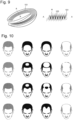
- FIG 10 a matrix of typical hair loss stages is shown. Depending on the physical constitution of the person affected, hair loss progresses through the stages from left to right. Starting on the left with full hair (shaded), a person affected by hair loss goes through an ever-growing forehead (1st row), or experiences circular hair loss (2nd row), with the circle constantly growing. The progressive stage of hair loss differs for some in that a circular tuft remains in the area of the upper forehead (3rd row). Another variant of the hair loss stages is shown in the 4th row. In these stages, the so-called "receding hairline” grows until baldness develops here too, which grows into a kind of tonsure in all stages. The effect of the device presented here for stimulating hair growth is to determine these different stages of hair loss and to carry out stimulation only in the affected areas of the scalp.
- FIG 11 and Figure 12 is shown how the electrode 101 ( Figure 11 ) and the detector device 103 lie directly on top of each other in layers. From above, the individual sketches in Figure 11 the view into the lining of the cap with visible foil electrode with spikes with round tips as contact point (see. Figure 4 ). In the middle picture, the cap with the sun visor tilts forward out of the plane of the paper. In order to show the foil electrode in this position, the cap has been hidden in the middle picture so that the foil electrode can be seen from the side that lies on the lining of the cap K. In this position, the concave foil electrode (cf. Figure 5 and Figure 6 ) or the concave arrangement of individual electrodes (cf. Figure 7 and Figure 8 ) to the affected surface of the head.
- the concave foil electrode cf. Figure 5 and Figure 6
- the concave arrangement of individual electrodes cf. Figure 7 and Figure 8
- the detector arrangement 103 is shown, which is directly connected to the foil electrode or to the arrangement of individual electrodes.
- the detector device 103 has several flat coils, with the help of which the status of hair loss at typical locations on the head can be detected via a local impedance measurement.
- the detectors are located to the left and right of the fontanelle.
- various electrical stimulation patterns are shown as example programs P1, P2, P3, P4, P5 and P6. It is possible, for example, to stimulate the scalp with short pulses with a frequency of 1 Hz to 4 Hz. To increase the effect of the stimulation, depolarization can be carried out first, as in the example programs P1 and P2. Depolarization is followed by polarization with a single pulse as in program P1 or a double pulse sequence as in program P2.
- the example program P3 consists of a slightly faster pulse sequence with uniform pulses without prior depolarization. It is also possible for the pulses to occur in pulse groups, as in the example program P4.
- the example program P5 shows a pulse sequence with around 25 Hz.
- pulse sequence is shown in program P6 with low-voltage pulses into which higher voltage pulses are inserted at a frequency of around 1 Hz.
- the frequency of the pulses can be between 1 Hz and 100 Hz and show different depolarization/polarization patterns.
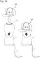
- FIG 14 Finally, a stand for the device for stimulating head hair growth 100 is shown, which is reminiscent of a wig stand.
- a coil 112 is inserted into the upper surface of the stand S, which is connected to a power supply cable V.
- the accumulator 110 of the device for stimulating head hair growth can be charged wirelessly via this coil 112.
- the Qi protocol which is also used in mobile phones, can be used as the charging protocol.
- the invention presented here is suitable for non-invasive electrostimulation of head hair growth when it is in the form of a hat or cap, and also for non-invasive electrostimulation of hair on other parts of the body, such as chest or back hair, armpit hair, but also pubic hair, or for stimulating beard growth when it is in the form of another item of clothing.
- the device it is possible for the device to be designed as a portable device in the form of a piece of clothing, as a so-called “wearable”, for example in the form of an outer garment, such as an undershirt, a T-shirt, a shirt, a sweater, a jacket, underpants, sports pants, an elastic bandage, such as a bandage to support the back muscles, or as a scarf or a beard bandage.
- a so-called “wearable” for example in the form of an outer garment, such as an undershirt, a T-shirt, a shirt, a sweater, a jacket, underpants, sports pants, an elastic bandage, such as a bandage to support the back muscles, or as a scarf or a beard bandage.
Landscapes
- Health & Medical Sciences (AREA)
- Life Sciences & Earth Sciences (AREA)
- Animal Behavior & Ethology (AREA)
- Engineering & Computer Science (AREA)
- Biomedical Technology (AREA)
- Nuclear Medicine, Radiotherapy & Molecular Imaging (AREA)
- Radiology & Medical Imaging (AREA)
- General Health & Medical Sciences (AREA)
- Public Health (AREA)
- Veterinary Medicine (AREA)
- Biophysics (AREA)
- Heart & Thoracic Surgery (AREA)
- Physiology (AREA)
- Electrotherapy Devices (AREA)
Applications Claiming Priority (2)
| Application Number | Priority Date | Filing Date | Title |
|---|---|---|---|
| DE102020121715.3A DE102020121715B4 (de) | 2020-08-19 | 2020-08-19 | Vorrichtung zur Stimulation des Haarwuchses |
| PCT/IB2021/057585 WO2022038529A1 (de) | 2020-08-19 | 2021-08-18 | Vorrichtung zur stimulation des haarwuchses |
Publications (3)
| Publication Number | Publication Date |
|---|---|
| EP4200009A1 EP4200009A1 (de) | 2023-06-28 |
| EP4200009C0 EP4200009C0 (de) | 2024-07-17 |
| EP4200009B1 true EP4200009B1 (de) | 2024-07-17 |
Family
ID=77801748
Family Applications (1)
| Application Number | Title | Priority Date | Filing Date |
|---|---|---|---|
| EP21772830.2A Active EP4200009B1 (de) | 2020-08-19 | 2021-08-18 | Vorrichtung zur stimulation des haarwuchses |
Country Status (8)
| Country | Link |
|---|---|
| US (1) | US20230310853A1 (enExample) |
| EP (1) | EP4200009B1 (enExample) |
| JP (1) | JP7693239B2 (enExample) |
| KR (1) | KR20230070214A (enExample) |
| CN (1) | CN116348178A (enExample) |
| DE (1) | DE102020121715B4 (enExample) |
| ES (1) | ES2992302T3 (enExample) |
| WO (1) | WO2022038529A1 (enExample) |
Families Citing this family (1)
| Publication number | Priority date | Publication date | Assignee | Title |
|---|---|---|---|---|
| WO2025100793A1 (ko) * | 2023-11-06 | 2025-05-15 | 에스에스비상사 주식회사 | 고주파 두피 마사지 장치 |
Family Cites Families (19)
| Publication number | Priority date | Publication date | Assignee | Title |
|---|---|---|---|---|
| JPH08173551A (ja) * | 1994-12-26 | 1996-07-09 | Kozo Oshio | 頭皮電気マッサージ用導子 |
| US6267720B1 (en) | 1999-07-07 | 2001-07-31 | Jo Rodney Knox | System and method for hair loss reduction and re-growth |
| JP2003339885A (ja) | 2002-05-31 | 2003-12-02 | Fes:Kk | 頭皮賦活用電気刺激装置 |
| JP2005194640A (ja) | 2003-12-26 | 2005-07-21 | Shinji Yoshizawa | 微弱電流による頭皮刺戟用帽子式電極構造とそれを用いた育毛及び脱毛防止器具 |
| KR100671943B1 (ko) | 2005-06-07 | 2007-01-24 | 이송자 | 두발성장을 돕는 두피조직 활성화 캡 |
| WO2008035910A1 (en) | 2006-09-22 | 2008-03-27 | Jeon Ho Ha | Massaging apparatus for head skin |
| US20100217369A1 (en) | 2009-01-07 | 2010-08-26 | Raibow Medical Ltd. | Hat for hair loss treatment |
| AU2012239966B2 (en) * | 2011-04-07 | 2015-11-26 | Oculeve, Inc. | Stimulation devices and methods |
| US11110272B2 (en) * | 2011-12-08 | 2021-09-07 | Pilogics L.P. | Apparatus for stimulating hair growth and/or preventing hair loss |
| RU2686427C2 (ru) | 2011-12-08 | 2019-04-25 | Пилоджикс Л.П. | Устройство и способ для стимуляции роста волос и/или предотвращения выпадения волос |
| US20160001073A1 (en) * | 2014-06-13 | 2016-01-07 | Pilogics L.P. | Apparatus and method for stimulating hair growth and/or preventing hair loss |
| US20140088670A1 (en) | 2012-09-25 | 2014-03-27 | Ines Verner Rashkovsky | Devices and methods for stimulation of hair growth |
| US20180015300A1 (en) | 2015-06-28 | 2018-01-18 | Theradome, Inc. | Coaching, documenting, reporting, and managing scalp hair recovery with laser photo-therapy devices |
| US20190143138A1 (en) * | 2017-08-22 | 2019-05-16 | Laserstim, Inc. | System and method to promote hair growth |
| CN108114378B (zh) * | 2018-02-07 | 2020-05-22 | 南昌仁恩医疗器械有限公司 | 一种育发装置 |
| CN209154906U (zh) * | 2018-07-13 | 2019-07-26 | 深圳市华越激光有限公司 | 一种自带人眼保护安全功能的低能量激光生发装置 |
| KR102204824B1 (ko) * | 2018-12-28 | 2021-01-19 | (주)셀리턴 | 헤어 상태 분석 기능을 갖는 헤어 관리 장치 |
| CN110694174A (zh) * | 2019-10-31 | 2020-01-17 | 深圳市刷新智能电子有限公司 | 一种多功能光电刺激生发帽 |
| JP6882806B2 (ja) * | 2020-03-18 | 2021-06-02 | 日本エステサービス株式会社 | 育毛促進装置 |
-
2020
- 2020-08-19 DE DE102020121715.3A patent/DE102020121715B4/de not_active Expired - Fee Related
-
2021
- 2021-08-18 KR KR1020237009280A patent/KR20230070214A/ko active Pending
- 2021-08-18 US US18/021,208 patent/US20230310853A1/en active Pending
- 2021-08-18 WO PCT/IB2021/057585 patent/WO2022038529A1/de not_active Ceased
- 2021-08-18 ES ES21772830T patent/ES2992302T3/es active Active
- 2021-08-18 EP EP21772830.2A patent/EP4200009B1/de active Active
- 2021-08-18 JP JP2023511997A patent/JP7693239B2/ja active Active
- 2021-08-18 CN CN202180069383.6A patent/CN116348178A/zh active Pending
Also Published As
| Publication number | Publication date |
|---|---|
| JP7693239B2 (ja) | 2025-06-17 |
| EP4200009A1 (de) | 2023-06-28 |
| CN116348178A (zh) | 2023-06-27 |
| EP4200009C0 (de) | 2024-07-17 |
| ES2992302T3 (es) | 2024-12-11 |
| KR20230070214A (ko) | 2023-05-22 |
| DE102020121715B4 (de) | 2024-01-11 |
| WO2022038529A1 (de) | 2022-02-24 |
| DE102020121715A1 (de) | 2022-02-24 |
| JP2023538579A (ja) | 2023-09-08 |
| US20230310853A1 (en) | 2023-10-05 |
Similar Documents
| Publication | Publication Date | Title |
|---|---|---|
| DE102006033623B4 (de) | System zur transkutanen Stimulation eines Nervs des menschlichen Körpers | |
| DE102008043973B4 (de) | Vorrichtung zur transkraniellen Neurostimulation | |
| Salenius et al. | Human cortical 40 Hz rhythm is closely related to EMG rhythmicity | |
| EP2866881B1 (de) | Vorrichtung zur muskulären stimulation | |
| DE102008052078B4 (de) | Vorrichtung zur konditionierten desynchronisierenden Stimulation | |
| EP2150311B1 (de) | Gerät zur punktual-stimulation | |
| WO2019145891A1 (de) | Bekleidungsstück und anordnung zur stimulation von körperbereichen und zur erfassung von daten sowie verfahren zur steuerung der anordnung | |
| US20130204315A1 (en) | Systems for and methods of transcranial direct current electrical stimulation | |
| EP0346513A1 (de) | Anordnung zur Elektrotherapie | |
| DE102014108315A1 (de) | Behandlungsvorrichtung und Behandlungsverfahren für das Gesicht | |
| DE102009017179A1 (de) | Vorrichtung zur komplexen Elektromyostimulation | |
| WO2014135636A1 (de) | Bekleidungsstück mit einer steuerungseinrichtung und mit elektroden zur stimulation von muskeln | |
| DE102020121715B4 (de) | Vorrichtung zur Stimulation des Haarwuchses | |
| WO2015188811A1 (de) | Behandlungsvorrichtung und behandlungsverfahren für das gesicht | |
| Insola et al. | Parallel processing of sensory inputs: an evoked potentials study in Parkinsonian patients implanted with thalamic stimulators | |
| WO2019145866A1 (de) | Elektrisch leitfähiges garn für elektroden eines bekleidungsstücks, bekleidungsstück und verfahren zur herstellung eines elektrisch leitfähigen garns für bekleidungsstücke zur stimulation und datenerfassung von körperbereichen | |
| DE102018101559B9 (de) | Bekleidungsstück zur Stimulation von Körperbereichen und Verfahren zu dessen Herstellung | |
| DE102018101565B3 (de) | Textiles Material und System zur Stimulation von Körperbereichen von Pferden | |
| WO2020099987A1 (de) | Textil zur stimulation von körperbereichen und bekleidungsstück daraus | |
| Liu et al. | Neuromorphic transcutaneous electrical nerve stimulation (nTENS) induces efficient tactile-related cortical networks in forearm amputees | |
| DE102024117735A1 (de) | Tragbare Vorrichtung zur elektrischen Stimulation von mindestens einem und/oder mehreren Nerven eines Benutzers und Verfahren zum Betreiben einer tragbaren Vorrichtung | |
| CN206587279U (zh) | 一种电极及具有该电极的骶神经植入刺激器 | |
| DE102024001712A1 (de) | Elektronische Schaltung zur Muskelstimulation und Steuerverfahren | |
| EP4568739A1 (de) | Nervenstimulationsvorrichtung zum elektrischen stimulieren zumindest eines nervs | |
| CN121606819A (zh) | 一种闭环控制的经皮迷走神经刺激系统及方法 |
Legal Events
| Date | Code | Title | Description |
|---|---|---|---|
| STAA | Information on the status of an ep patent application or granted ep patent |
Free format text: STATUS: UNKNOWN |
|
| STAA | Information on the status of an ep patent application or granted ep patent |
Free format text: STATUS: THE INTERNATIONAL PUBLICATION HAS BEEN MADE |
|
| PUAI | Public reference made under article 153(3) epc to a published international application that has entered the european phase |
Free format text: ORIGINAL CODE: 0009012 |
|
| STAA | Information on the status of an ep patent application or granted ep patent |
Free format text: STATUS: REQUEST FOR EXAMINATION WAS MADE |
|
| 17P | Request for examination filed |
Effective date: 20230308 |
|
| AK | Designated contracting states |
Kind code of ref document: A1 Designated state(s): AL AT BE BG CH CY CZ DE DK EE ES FI FR GB GR HR HU IE IS IT LI LT LU LV MC MK MT NL NO PL PT RO RS SE SI SK SM TR |
|
| DAV | Request for validation of the european patent (deleted) | ||
| DAX | Request for extension of the european patent (deleted) | ||
| GRAP | Despatch of communication of intention to grant a patent |
Free format text: ORIGINAL CODE: EPIDOSNIGR1 |
|
| STAA | Information on the status of an ep patent application or granted ep patent |
Free format text: STATUS: GRANT OF PATENT IS INTENDED |
|
| INTG | Intention to grant announced |
Effective date: 20240403 |
|
| GRAS | Grant fee paid |
Free format text: ORIGINAL CODE: EPIDOSNIGR3 |
|
| GRAA | (expected) grant |
Free format text: ORIGINAL CODE: 0009210 |
|
| STAA | Information on the status of an ep patent application or granted ep patent |
Free format text: STATUS: THE PATENT HAS BEEN GRANTED |
|
| AK | Designated contracting states |
Kind code of ref document: B1 Designated state(s): AL AT BE BG CH CY CZ DE DK EE ES FI FR GB GR HR HU IE IS IT LI LT LU LV MC MK MT NL NO PL PT RO RS SE SI SK SM TR |
|
| REG | Reference to a national code |
Ref country code: CH Ref legal event code: EP |
|
| REG | Reference to a national code |
Ref country code: DE Ref legal event code: R096 Ref document number: 502021004426 Country of ref document: DE |
|
| REG | Reference to a national code |
Ref country code: IE Ref legal event code: FG4D Free format text: LANGUAGE OF EP DOCUMENT: GERMAN |
|
| U01 | Request for unitary effect filed |
Effective date: 20240809 |
|
| U07 | Unitary effect registered |
Designated state(s): AT BE BG DE DK EE FI FR IT LT LU LV MT NL PT SE SI Effective date: 20240826 |
|
| U20 | Renewal fee for the european patent with unitary effect paid |
Year of fee payment: 4 Effective date: 20241008 |
|
| REG | Reference to a national code |
Ref country code: ES Ref legal event code: FG2A Ref document number: 2992302 Country of ref document: ES Kind code of ref document: T3 Effective date: 20241211 |
|
| PG25 | Lapsed in a contracting state [announced via postgrant information from national office to epo] |
Ref country code: NO Free format text: LAPSE BECAUSE OF FAILURE TO SUBMIT A TRANSLATION OF THE DESCRIPTION OR TO PAY THE FEE WITHIN THE PRESCRIBED TIME-LIMIT Effective date: 20241017 |
|
| PG25 | Lapsed in a contracting state [announced via postgrant information from national office to epo] |
Ref country code: PL Free format text: LAPSE BECAUSE OF FAILURE TO SUBMIT A TRANSLATION OF THE DESCRIPTION OR TO PAY THE FEE WITHIN THE PRESCRIBED TIME-LIMIT Effective date: 20240717 Ref country code: GR Free format text: LAPSE BECAUSE OF FAILURE TO SUBMIT A TRANSLATION OF THE DESCRIPTION OR TO PAY THE FEE WITHIN THE PRESCRIBED TIME-LIMIT Effective date: 20241018 |
|
| PG25 | Lapsed in a contracting state [announced via postgrant information from national office to epo] |
Ref country code: IS Free format text: LAPSE BECAUSE OF FAILURE TO SUBMIT A TRANSLATION OF THE DESCRIPTION OR TO PAY THE FEE WITHIN THE PRESCRIBED TIME-LIMIT Effective date: 20241117 |
|
| PG25 | Lapsed in a contracting state [announced via postgrant information from national office to epo] |
Ref country code: HR Free format text: LAPSE BECAUSE OF FAILURE TO SUBMIT A TRANSLATION OF THE DESCRIPTION OR TO PAY THE FEE WITHIN THE PRESCRIBED TIME-LIMIT Effective date: 20240717 |
|
| PG25 | Lapsed in a contracting state [announced via postgrant information from national office to epo] |
Ref country code: RS Free format text: LAPSE BECAUSE OF FAILURE TO SUBMIT A TRANSLATION OF THE DESCRIPTION OR TO PAY THE FEE WITHIN THE PRESCRIBED TIME-LIMIT Effective date: 20241017 |
|
| PG25 | Lapsed in a contracting state [announced via postgrant information from national office to epo] |
Ref country code: RS Free format text: LAPSE BECAUSE OF FAILURE TO SUBMIT A TRANSLATION OF THE DESCRIPTION OR TO PAY THE FEE WITHIN THE PRESCRIBED TIME-LIMIT Effective date: 20241017 Ref country code: PL Free format text: LAPSE BECAUSE OF FAILURE TO SUBMIT A TRANSLATION OF THE DESCRIPTION OR TO PAY THE FEE WITHIN THE PRESCRIBED TIME-LIMIT Effective date: 20240717 Ref country code: NO Free format text: LAPSE BECAUSE OF FAILURE TO SUBMIT A TRANSLATION OF THE DESCRIPTION OR TO PAY THE FEE WITHIN THE PRESCRIBED TIME-LIMIT Effective date: 20241017 Ref country code: IS Free format text: LAPSE BECAUSE OF FAILURE TO SUBMIT A TRANSLATION OF THE DESCRIPTION OR TO PAY THE FEE WITHIN THE PRESCRIBED TIME-LIMIT Effective date: 20241117 Ref country code: HR Free format text: LAPSE BECAUSE OF FAILURE TO SUBMIT A TRANSLATION OF THE DESCRIPTION OR TO PAY THE FEE WITHIN THE PRESCRIBED TIME-LIMIT Effective date: 20240717 Ref country code: GR Free format text: LAPSE BECAUSE OF FAILURE TO SUBMIT A TRANSLATION OF THE DESCRIPTION OR TO PAY THE FEE WITHIN THE PRESCRIBED TIME-LIMIT Effective date: 20241018 |
|
| PG25 | Lapsed in a contracting state [announced via postgrant information from national office to epo] |
Ref country code: SM Free format text: LAPSE BECAUSE OF FAILURE TO SUBMIT A TRANSLATION OF THE DESCRIPTION OR TO PAY THE FEE WITHIN THE PRESCRIBED TIME-LIMIT Effective date: 20240717 |
|
| PG25 | Lapsed in a contracting state [announced via postgrant information from national office to epo] |
Ref country code: MC Free format text: LAPSE BECAUSE OF FAILURE TO SUBMIT A TRANSLATION OF THE DESCRIPTION OR TO PAY THE FEE WITHIN THE PRESCRIBED TIME-LIMIT Effective date: 20240717 |
|
| PG25 | Lapsed in a contracting state [announced via postgrant information from national office to epo] |
Ref country code: CZ Free format text: LAPSE BECAUSE OF FAILURE TO SUBMIT A TRANSLATION OF THE DESCRIPTION OR TO PAY THE FEE WITHIN THE PRESCRIBED TIME-LIMIT Effective date: 20240717 |
|
| PG25 | Lapsed in a contracting state [announced via postgrant information from national office to epo] |
Ref country code: SK Free format text: LAPSE BECAUSE OF FAILURE TO SUBMIT A TRANSLATION OF THE DESCRIPTION OR TO PAY THE FEE WITHIN THE PRESCRIBED TIME-LIMIT Effective date: 20240717 |
|
| PLBE | No opposition filed within time limit |
Free format text: ORIGINAL CODE: 0009261 |
|
| STAA | Information on the status of an ep patent application or granted ep patent |
Free format text: STATUS: NO OPPOSITION FILED WITHIN TIME LIMIT |
|
| 26N | No opposition filed |
Effective date: 20250422 |
|
| PG25 | Lapsed in a contracting state [announced via postgrant information from national office to epo] |
Ref country code: IE Free format text: LAPSE BECAUSE OF NON-PAYMENT OF DUE FEES Effective date: 20240818 |
|
| U20 | Renewal fee for the european patent with unitary effect paid |
Year of fee payment: 5 Effective date: 20250812 |
|
| PGFP | Annual fee paid to national office [announced via postgrant information from national office to epo] |
Ref country code: ES Payment date: 20250917 Year of fee payment: 5 |
|
| PGFP | Annual fee paid to national office [announced via postgrant information from national office to epo] |
Ref country code: GB Payment date: 20250818 Year of fee payment: 5 |
|
| PGFP | Annual fee paid to national office [announced via postgrant information from national office to epo] |
Ref country code: CH Payment date: 20250901 Year of fee payment: 5 |
|
| PG25 | Lapsed in a contracting state [announced via postgrant information from national office to epo] |
Ref country code: RO Free format text: LAPSE BECAUSE OF FAILURE TO SUBMIT A TRANSLATION OF THE DESCRIPTION OR TO PAY THE FEE WITHIN THE PRESCRIBED TIME-LIMIT Effective date: 20240717 |
|
| PG25 | Lapsed in a contracting state [announced via postgrant information from national office to epo] |
Ref country code: CY Free format text: LAPSE BECAUSE OF FAILURE TO SUBMIT A TRANSLATION OF THE DESCRIPTION OR TO PAY THE FEE WITHIN THE PRESCRIBED TIME-LIMIT; INVALID AB INITIO Effective date: 20210818 |
|
| PG25 | Lapsed in a contracting state [announced via postgrant information from national office to epo] |
Ref country code: HU Free format text: LAPSE BECAUSE OF FAILURE TO SUBMIT A TRANSLATION OF THE DESCRIPTION OR TO PAY THE FEE WITHIN THE PRESCRIBED TIME-LIMIT; INVALID AB INITIO Effective date: 20210818 |