EP4199822B1 - Dispositif d'échantillonnage de sang - Google Patents
Dispositif d'échantillonnage de sang Download PDFInfo
- Publication number
- EP4199822B1 EP4199822B1 EP21859085.9A EP21859085A EP4199822B1 EP 4199822 B1 EP4199822 B1 EP 4199822B1 EP 21859085 A EP21859085 A EP 21859085A EP 4199822 B1 EP4199822 B1 EP 4199822B1
- Authority
- EP
- European Patent Office
- Prior art keywords
- lancet
- axis
- spring
- connector
- lancing device
- Prior art date
- Legal status (The legal status is an assumption and is not a legal conclusion. Google has not performed a legal analysis and makes no representation as to the accuracy of the status listed.)
- Active
Links
Images


Classifications
-
- A—HUMAN NECESSITIES
- A61—MEDICAL OR VETERINARY SCIENCE; HYGIENE
- A61B—DIAGNOSIS; SURGERY; IDENTIFICATION
- A61B5/00—Measuring for diagnostic purposes; Identification of persons
- A61B5/15—Devices for taking samples of blood
- A61B5/150007—Details
- A61B5/150015—Source of blood
- A61B5/150022—Source of blood for capillary blood or interstitial fluid
-
- A—HUMAN NECESSITIES
- A61—MEDICAL OR VETERINARY SCIENCE; HYGIENE
- A61B—DIAGNOSIS; SURGERY; IDENTIFICATION
- A61B5/00—Measuring for diagnostic purposes; Identification of persons
- A61B5/15—Devices for taking samples of blood
- A61B5/150007—Details
- A61B5/150053—Details for enhanced collection of blood or interstitial fluid at the sample site, e.g. by applying compression, heat, vibration, ultrasound, suction or vacuum to tissue; for reduction of pain or discomfort; Skin piercing elements, e.g. blades, needles, lancets or canulas, with adjustable piercing speed
- A61B5/150061—Means for enhancing collection
- A61B5/150083—Means for enhancing collection by vibration, e.g. ultrasound
-
- A—HUMAN NECESSITIES
- A61—MEDICAL OR VETERINARY SCIENCE; HYGIENE
- A61B—DIAGNOSIS; SURGERY; IDENTIFICATION
- A61B5/00—Measuring for diagnostic purposes; Identification of persons
- A61B5/15—Devices for taking samples of blood
- A61B5/150007—Details
- A61B5/150053—Details for enhanced collection of blood or interstitial fluid at the sample site, e.g. by applying compression, heat, vibration, ultrasound, suction or vacuum to tissue; for reduction of pain or discomfort; Skin piercing elements, e.g. blades, needles, lancets or canulas, with adjustable piercing speed
- A61B5/150106—Means for reducing pain or discomfort applied before puncturing; desensitising the skin at the location where body is to be pierced
- A61B5/150137—Means for reducing pain or discomfort applied before puncturing; desensitising the skin at the location where body is to be pierced by vibration
-
- A—HUMAN NECESSITIES
- A61—MEDICAL OR VETERINARY SCIENCE; HYGIENE
- A61B—DIAGNOSIS; SURGERY; IDENTIFICATION
- A61B5/00—Measuring for diagnostic purposes; Identification of persons
- A61B5/15—Devices for taking samples of blood
- A61B5/150007—Details
- A61B5/150374—Details of piercing elements or protective means for preventing accidental injuries by such piercing elements
- A61B5/150381—Design of piercing elements
- A61B5/150412—Pointed piercing elements, e.g. needles, lancets for piercing the skin
- A61B5/150435—Specific design of proximal end
-
- A—HUMAN NECESSITIES
- A61—MEDICAL OR VETERINARY SCIENCE; HYGIENE
- A61B—DIAGNOSIS; SURGERY; IDENTIFICATION
- A61B5/00—Measuring for diagnostic purposes; Identification of persons
- A61B5/15—Devices for taking samples of blood
- A61B5/151—Devices specially adapted for taking samples of capillary blood, e.g. by lancets, needles or blades
- A61B5/15101—Details
- A61B5/15103—Piercing procedure
- A61B5/15107—Piercing being assisted by a triggering mechanism
- A61B5/15113—Manually triggered, i.e. the triggering requires a deliberate action by the user such as pressing a drive button
-
- A—HUMAN NECESSITIES
- A61—MEDICAL OR VETERINARY SCIENCE; HYGIENE
- A61B—DIAGNOSIS; SURGERY; IDENTIFICATION
- A61B5/00—Measuring for diagnostic purposes; Identification of persons
- A61B5/15—Devices for taking samples of blood
- A61B5/151—Devices specially adapted for taking samples of capillary blood, e.g. by lancets, needles or blades
- A61B5/15101—Details
- A61B5/15115—Driving means for propelling the piercing element to pierce the skin, e.g. comprising mechanisms based on shape memory alloys, magnetism, solenoids, piezoelectric effect, biased elements, resilient elements, vacuum or compressed fluids
- A61B5/15117—Driving means for propelling the piercing element to pierce the skin, e.g. comprising mechanisms based on shape memory alloys, magnetism, solenoids, piezoelectric effect, biased elements, resilient elements, vacuum or compressed fluids comprising biased elements, resilient elements or a spring, e.g. a helical spring, leaf spring, or elastic strap
-
- A—HUMAN NECESSITIES
- A61—MEDICAL OR VETERINARY SCIENCE; HYGIENE
- A61B—DIAGNOSIS; SURGERY; IDENTIFICATION
- A61B5/00—Measuring for diagnostic purposes; Identification of persons
- A61B5/15—Devices for taking samples of blood
- A61B5/151—Devices specially adapted for taking samples of capillary blood, e.g. by lancets, needles or blades
- A61B5/15101—Details
- A61B5/15126—Means for controlling the lancing movement, e.g. 2D- or 3D-shaped elements, tooth-shaped elements or sliding guides
- A61B5/15128—Means for controlling the lancing movement, e.g. 2D- or 3D-shaped elements, tooth-shaped elements or sliding guides comprising 2D- or 3D-shaped elements, e.g. cams, curved guide rails or threads
-
- A—HUMAN NECESSITIES
- A61—MEDICAL OR VETERINARY SCIENCE; HYGIENE
- A61B—DIAGNOSIS; SURGERY; IDENTIFICATION
- A61B5/00—Measuring for diagnostic purposes; Identification of persons
- A61B5/15—Devices for taking samples of blood
- A61B5/151—Devices specially adapted for taking samples of capillary blood, e.g. by lancets, needles or blades
- A61B5/15101—Details
- A61B5/15126—Means for controlling the lancing movement, e.g. 2D- or 3D-shaped elements, tooth-shaped elements or sliding guides
- A61B5/1513—Means for controlling the lancing movement, e.g. 2D- or 3D-shaped elements, tooth-shaped elements or sliding guides comprising linear sliding guides
-
- A—HUMAN NECESSITIES
- A61—MEDICAL OR VETERINARY SCIENCE; HYGIENE
- A61B—DIAGNOSIS; SURGERY; IDENTIFICATION
- A61B5/00—Measuring for diagnostic purposes; Identification of persons
- A61B5/15—Devices for taking samples of blood
- A61B5/151—Devices specially adapted for taking samples of capillary blood, e.g. by lancets, needles or blades
- A61B5/15101—Details
- A61B5/15126—Means for controlling the lancing movement, e.g. 2D- or 3D-shaped elements, tooth-shaped elements or sliding guides
- A61B5/15132—Means for controlling the lancing movement, e.g. 2D- or 3D-shaped elements, tooth-shaped elements or sliding guides comprising tooth-shaped elements, e.g. toothed wheel or rack and pinion
-
- A—HUMAN NECESSITIES
- A61—MEDICAL OR VETERINARY SCIENCE; HYGIENE
- A61B—DIAGNOSIS; SURGERY; IDENTIFICATION
- A61B5/00—Measuring for diagnostic purposes; Identification of persons
- A61B5/15—Devices for taking samples of blood
- A61B5/151—Devices specially adapted for taking samples of capillary blood, e.g. by lancets, needles or blades
- A61B5/15186—Devices loaded with a single lancet, i.e. a single lancet with or without a casing is loaded into a reusable drive device and then discarded after use; drive devices reloadable for multiple use
- A61B5/15188—Constructional features of reusable driving devices
- A61B5/1519—Constructional features of reusable driving devices comprising driving means, e.g. a spring, for propelling the piercing unit
-
- A—HUMAN NECESSITIES
- A61—MEDICAL OR VETERINARY SCIENCE; HYGIENE
- A61B—DIAGNOSIS; SURGERY; IDENTIFICATION
- A61B5/00—Measuring for diagnostic purposes; Identification of persons
- A61B5/15—Devices for taking samples of blood
- A61B5/151—Devices specially adapted for taking samples of capillary blood, e.g. by lancets, needles or blades
- A61B5/15186—Devices loaded with a single lancet, i.e. a single lancet with or without a casing is loaded into a reusable drive device and then discarded after use; drive devices reloadable for multiple use
- A61B5/15188—Constructional features of reusable driving devices
- A61B5/15192—Constructional features of reusable driving devices comprising driving means, e.g. a spring, for retracting the lancet unit into the driving device housing
- A61B5/15194—Constructional features of reusable driving devices comprising driving means, e.g. a spring, for retracting the lancet unit into the driving device housing fully automatically retracted, i.e. the retraction does not require a deliberate action by the user, e.g. by terminating the contact with the patient's skin
-
- A—HUMAN NECESSITIES
- A61—MEDICAL OR VETERINARY SCIENCE; HYGIENE
- A61B—DIAGNOSIS; SURGERY; IDENTIFICATION
- A61B5/00—Measuring for diagnostic purposes; Identification of persons
- A61B5/15—Devices for taking samples of blood
- A61B5/150007—Details
- A61B5/150053—Details for enhanced collection of blood or interstitial fluid at the sample site, e.g. by applying compression, heat, vibration, ultrasound, suction or vacuum to tissue; for reduction of pain or discomfort; Skin piercing elements, e.g. blades, needles, lancets or canulas, with adjustable piercing speed
- A61B5/150106—Means for reducing pain or discomfort applied before puncturing; desensitising the skin at the location where body is to be pierced
- A61B5/150152—Means for reducing pain or discomfort applied before puncturing; desensitising the skin at the location where body is to be pierced by an adequate mechanical impact on the puncturing location
Definitions
- the present disclosure relates to a lancing device for extracting a blood sample.
- blood samples need to be drawn from a person.
- a lancing device for collect blood samples comfortably without excessive pain is desired.
- US2009024009 discloses a body fluid sensing device with a body fluid capture structure and a body fluid measurement sensor positioned in the body fluid capture structure, wherein a capacitance sensor is coupled to the body fluid measurement sensor, and the capacitance sensor is used to assist in the positioning of a body part relative to the body fluid capture structure.
- the main body portion is a hand-gripping portion configured for gripping with one hand of a person.
- the tip portion comprises a skin contact surface or edge for contacting a skin area from which blood is to be sampled.
- the tip portion further comprises an opening through which a needle is to travel.
- the lancet receiving portion connects the main body portion and the tip portion therebetween.
- the lancet connector comprises an engagement portion configured to engage with a counterpart component of the lancet body for integrating the lancet with the lancet connector.
- the lancet Upon integrating the lancet with the lancet connector without triggering the reciprocating actuator, the lancet is generally located in or on the lancet receiving portion of the lancing device body, in which the needle extends in a forward direction along the axis away from the main body portion but does not extend beyond the skin contact surface in the forward direction such that a distal end of the needle would not and does not stab the skin area even if the tip portion is place on the skin area.
- the reciprocating actuator may comprise a cam and a cam follower operably connected to the cam to generate the linear reciprocating motion in the forward direction and the backward direction along the axis.
- the lancet connector may be operably connected to cam follower for the linear reciprocating motion.
- the reciprocating actuator may further comprise a rack gear elongated generally in the axis and a pinion gear engaged with the rack gear.
- the pinion gear may be operably engaged with the rack gear and further operably connected to the cam such that sliding of the rack gear along the axis causes rotation of the pinion gear which further causes rotation of the cam about the cam axis.
- the reciprocating actuator may further comprise a handle disposed outside the main body portion and configured for pulling in the backward direction along the axis relative to the lancing device body.
- the handle may be connected to the rack gear for sliding the rack gear in the backward direction relative to the pinion gear when the handle is pulled in the backward direction.
- the reciprocating actuator may comprise an electromechanical reciprocating actuator which may comprise a motor configured to generate a rotational force to rotate the cam.
- the trigger may comprise an electrical switch configured to turn on the motor.
- the reciprocating actuator may comprise a spring-loaded reciprocating actuator which may comprise a spring mechanism configured to store spring energy for generating a rotational force to rotate the cam, wherein the trigger may be configured to initiate a release of the spring energy.
- the trigger may be located on an exterior of the main body portion opposite to the tip portion such that, when the lancing device body may be gripped with one hand of the person, a finger of the same hand or another hand may apply an external force to the trigger.
- the reciprocating actuator may be configured to initiate an actuating operation in response to the external force applied to the trigger.
- the arm comprises a first connection portion hingedly connected with the lancet connector for hinged rotation relative to the lancet connector about a second axis generally perpendicular to the first axis.
- the arm comprises a second connection portion distanced from the first connection portion and engaged with the zigzag guide such that the second connection portion is to travel along the zigzag guide as the zigzag guide member moves in the forward direction and in the backward direction along the first axis.
- the arm further comprises a third connection portion distanced from the first connection portion and engaged with a linear guide that is provided inside the main body portion and extends in a third axis generally perpendicular to the first axis and further to the second axis such that the third connection portion is to travel along the linear guide between two lateral positions in the third axis.
- the trigger is configured to initiate a release of the spring energy.
- the zigzag guide member slides in the forward direction, which causes the second connection portion to travel relative to the zigzag guide member along the zigzag guide, which further causes the hinged rotation of the arm about the second axis relative to the lancet connector, while the third connection portion of the arm travels along the linear guide between the two lateral positions in the third axis, which further causes the arm to push the lancet connector in the forward direction and pull the lancet connector in the backward direction to make the linear reciprocating motion of the lancet connector.
- the zigzag guide may comprise at least one guide groove formed into the zigzag guide member that extends in a zigzag pattern when viewed in the second axis.
- the second connection portion of the arm may be sized and shaped for engaging with the at least one guide groove for traveling along the third axis as the zigzag guide member slides in the forward direction and in the backward direction.
- the zigzag guide may comprise at least one guide rail formed on the zigzag guide member that extends in a zigzag pattern when viewed in the second axis.
- the second connection portion of the arm may be sized and shaped for engaging with the at least one guide rail for traveling along the third axis as the zigzag guide member slides in the forward direction and in the backward direction.
- the linear guide may comprise a linear guide channel defined inside the main body and extending in the third axis.
- the third connection portion may be inserted in the linear guide channel and restricted to travel only along the linear guide channel between the two lateral positions in the third axis.
- the arm may be configured to hingedly rotate on an imaginary plane generally parallel to the plane defined by the first axis and the third axis.
- the second connection portion extends generally in the second axis further from the third connection portion to engage with the zigzag guide.
- the reciprocating actuator may further comprise a spring guide configured to guide and keep the spring within a space it defines as the spring compresses and extends.
- the spring guide may comprise a spring contact surface which one end of the spring contacts.
- the zigzag guide member may be integrated with the spring guide, wherein, as the spring energy is released, the spring is configured to push the spring contact surface, which causes the spring guide to travel in the forward direction and accordingly moves the zigzag guide member in the forward direction relative to the main body portion.
- the reciprocating actuator may further comprise a handle connected to the spring guide and exposed outside the main body portion at an opposite end of the tip portion.
- the handle is configured to be pulled in the backward direction relative to the main body portion, which causes the spring guide to travel in the backward direction and compresses the spring.
- the reciprocating actuator may further comprise a latch configured to stop the movement of the handle in the backward direction beyond a predetermine point in the main body portion, at which the spring may be compressed and stores the spring energy, wherein the trigger may be configured to initiate the release of the spring energy.
- the lancet receiving portion may comprise a channel extending in the axis for aligning the needle when connecting the lancet to the lancet connector.
- the lancet receiving portion may further comprise a recess configured to receive the lancet body and permits a linear movement of the lancet body along the axis when the lancet is connected to the lancet connector and the lancet advances in the forward direction and retreats in the backward direction along the axis.
- the lancet receiving portion may further comprise a step configured to block the lancet body from advancing further in the forward direction.
- the lancet may comprise at least one wing extending from the lancet body in a direction generally perpendicular to the extension of the needle from the lancet body.
- a lancing system comprising any of the foregoing lancing devices and a lancet comprising a lancet body and a needle extending from the lancet body. Also disclosed is a non claimed method of sampling blood with any of the foregoing lancing device or system.
- the gauge size or diameter of the needle can be determined to obtain the required amount of blood sample in a single operation. If the diameter of the lancet is too small, capillaries may not be ruptured enough and a sufficient amount of blood may not come out. Also, if the opening formed into the skin is too small, it will be difficult for the blood to flow out. However, if the diameter of the lancet needle is too large, the needle may hit or touch pain receptors distributed under the skin, which will cause pain every time the lancet is used. Some people are extremely sensitive to such pain. Diabetic patients who lance 3 to 4 times a day may find this procedure uncomfortable. In addition, calluses may develop when the lancet is used repeatedly in one spot.
- a lancet needle having a smaller diameter is less likely to touch pain receptors under skin and accordingly may reduce the discomfort and pain when collecting blood using the lancet. If a small diameter lancet needle is used to lance the same skin location multiple times, more capillaries could be ruptured and more blood could be obtained without causing the discomfort or pain from larger lancet needles. However, multiple lancing on the same skin location is difficult to accomplish when using a lancing device designed for a single lancing.
- the needle 142 has an elongated body for piercing the skin.
- the needle 142 has a generally circular cross-section although not limited thereto.
- the needle 142 may have a generally tapered shape toward the tip thereof, although not limited thereto.
- the needle 142 may be in a tubular configuration, although not limited thereto.
- the length of the needle 142 beyond the lancet body 144 to its tip is about 0.3, 0.4, 0.5, 0.6, 0.7, 0.8, 0.9, 1.0, 1.1, 1.2, 1.3, 1.4, 1.5, 1.6, 1.7, 1.8, 1.9 or 2.0 cm.
- the length may be in a range between two numbers selected from those listed in the immediately previous sentence.
- the length of the needle 142 is chosen in view of the size and configuration of the lancing device 100. Also, the length may be chosen in view of the subject to which multiple lancing is used. For example, when the multiple lancing is used for an animal with a thick skin, a longer needle may be appropriate. Again, the needle tip does not extend beyond the lancing device 100 when the device is not operating for lancing.
- the diameter of needles is typically represented in a gauge number.
- a 20 gauge needle has 0.9081 mm outer diameter
- a 25 gauge needle has 0.5144 mm outer diameter
- a 30 gauge needle has 0.3112 mm outer diameter
- a 34 gauge needle has 0.1842 mm outer diameter.
- the needle 142 for multiple lancing has 36, 35, 34, 33, 32, 31, 30, 29, 28, 27, 26, 25, 24, 23, 22, 21, 20, 19, 18, 17, 16, 15, 14, 13, 12, 11, or 10 gauge number.
- the gauge number may be in a range between two numbers selected from those listed in the immediately previous sentence.
- the gauge number of the needle 142 is chosen in view of the skin location and/or the subject to which multiple lancing is applied.
- a thinner needle is to be used to a skin area of a person where pain receptors are abundant or crowded
- a thicker needle is to be used to a skin area where pain receptors are scarce.
- the lancet body 144 additionally includes a lancet body wing 144b.
- the lancet body wing 144b may extend from the main lancet body 144a in an approximately right angle with the needle 142.
- the lancet body wing 144b may make it easy for the user to hold the lancet 140.
- the lancet body 144 additionally includes a lancet body engagement portion 144c that extends from the main lancet body 144a in the opposite direction to the needle 142.
- This lancet body engagement portion 144c is configured to engage and couple to the lancing device 100, more specifically to lancet connector 134.
- the extension of the needle 142 may coincide with the first axis
- the lancet body wing 144b may coincide with the second axis that is perpendicular to the first axis.
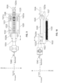
- the lancing device body 110 includes a main body 112, a front-end portion 135, and a lancet receiving portion 130. As illustrated, the lancet receiving portion 130 is interposed between the main body 112 and the front-end portion 135 and connects the two components.
- the main body 112 serves as a housing that accommodates some components of the lancing device 100.
- the main body 112 may generally extend along the first axis.
- the main body 112 provides surfaces that a user grips and holds with a hand for use.
- the main body 112 is in a size and thickness that can be held with one hand.
- the front-end portion 135 is formed at one end of the lancing device 100.
- the front-end portion 135 may include a skin contacting surface 135a and a hole 135b formed through the skin contacting surface 135a.
- the skin contacting surface 135a is to contact with the skin when the lancing device 100 is positioned on the skin for blood sampling.
- the hole 135b provides a passage through which the needle 142 travels back and forth.
- the lancet receiving portion 130 is a portion in which the lancet 140 is accommodated between the front-end portion 135 and the main body 112.
- the lancet receiving portion 130 includes a lancet guide groove 136a and a recess 136b to receive the lancet body 140 when the lancet 140 is connected to the lancet connector 134.
- the length of the lancet receiving portion 130 in the first axis may be slightly greater than the overall length of the lancet 140 so that the lancet receiving portion 130 can easily accommodate the lancet 140.
- the lancet receiving portion 130 may be integrally formed with the main body 112.
- the lancet receiving portion 130 may include a lancet guide groove 136a that extends along the first axis as shown in FIGS 1 and 2 .
- the groove 136a may have a shape to accommodate the shape of the lancet main body 144a, and the size of the groove 136 can be slightly greater than the size of the lancet main body 144a.
- the groove 136 may facilitate aligning the needle 142 when positioning the lancet 140 at the lancet receiving portion 130. In operation, the needle 142 or lancet main body 144a may or may not contact surfaces of the lancet guide groove.
- the actuation member 124 has an elongated body integrated with the handle 122 at one end and the guide member 128 at the other end.
- the elongated body includes a spring space 124a for accommodating the spring 150 with an end piece 124b.
- the handle 122, the actuation member 124 and the guide member 128 are arranged in order and formed in a single piece.
- the single piece is produced by injection molding to form the single piece component.
- the first accommodating space 154 may be a groove or channel formed inside the main body 112.
- the actuation member 124 and the guide member 128 of the actuator 120 are accommodated within the first accommodating space 154 and slidable forward and backward along the first axis relative to the lancing device body 110.
- the second accommodating space 158 may be a groove or channel formed inside the main body 112.
- first accommodating space 154 and the second accommodating space 158 are separated by the bridge 156. However, the first and second accommodating spaces 154 and 158 are connected with each other via an opening (not shown) underneath the bridge 156.
- the spring 150 is inserted between the spring stop 152 and the end piece 124b within the spring space 124a of the actuation member 124.
- the spring 150 may be replaced with an elastic device that can generate power by a linear expansion or compression along its length.
- One end of the spring 150 abuts and/or is fixed to the end piece 124b of the actuation member 124.
- the other end of the spring 150 abuts and/or is fixed to the spring stop 152 formed in the first accommodation space 154 of the main body 112. Accordingly, the spring 150 is interposed between one end piece 124b (of the actuation member 124) and the spring stop 152 (of the main body 112).
- the spring 150 is a compression spring, the spring accumulates energy in it when the spring is compressed by pushing the handle 122 in the forward direction relative to the lancing device body 112. If the spring is an extension spring, the spring accumulates energy in it when the spring is extended by pulling the handle 122 in the backward direction relative to the lancing device body 112.
- FIG 4A illustrates a fully relaxed state of the actuator 120, in which the spring 150 is fully expanded and the guide member 128 is fully advanced into the second accommodation space 158.
- the actuation member 124 and the guide member 128 move backward. A portion of the actuation member 124 extends beyond and outside the lancing device body 110, and the guide member 128 moves from the second accommodation space 158 to the first accommodation space 154. Further, the end piece 124b of the actuation member 124 will compress the spring 150 toward the spring stop 152 of the main body 112, which will load the actuator 120 to the loaded state of FIG 4B .
- a latch 116a may be connected to the actuator 120 inside the main body 112.
- the latch 116a may selectively keep the actuator 120 at a predetermined position.
- FIG 4B illustrates that the latch 116a keeps the actuator 120 at its loaded state, in which the tip of the latch 116a contacts a leading edge of the guide member 128 and blocks the guide member 128 from moving into the second accommodation space 158.
- the latch 116a may selectively release the actuator 120 from the predetermined position at the loaded state and start the actuator 120.
- a mechanical or electrical button 116 may cause the latch 116a to release the guide member 128 or the loaded state of the actuator 120.
- the latch 116 may release the guide member 128, which then causes the spring 150 to expand and push the guide member 128 to move into the second accommodation space 158.
- the button for the latch 116a may be disposed on the side of the main body 112, so that the user can press the button 116 while holding the lancing device 100 with one hand.
- the pair of straight arms 138 operably connects between the guide member 128 and the lancet connector 134 for the linear reciprocal movement of the lancet connector 134.
- Each arm 138 includes a first connection portion connecting with the lancet connector 134 and a second connection portion connecting with the guide member 128.
- Each arm 138 includes the first connection portion at or near its end next to the lancet connector 134.
- the first connection portion (or first end portion) of each arm 138 hingedly connects with a counterpart mechanism provided in the lancet connector 134.
- the lancet connector 134 includes a hinge pin (not illustrated), and each arm's first connection portion includes a hole that receives the hinge pin, which allows the arm hingedly moves about the hinge pin, i.e., hinge axis of the lancet connector 134 and generally on a plane formed by the first and third axes.
- a lancet connector 1034 has a cylindrical shape with a circular or oval cross-section.
- the lancet connector 1034 is integral to the lancet connector base 1034a located over the actuator housing 1022, although not limited thereto.
- the lancet connector base 1034a is integrated to the front end portion of the cam follower 1029 by the pin 1029a. As the front end portion of the cam follower 1029 travels forward and backward in the first axis, the lancet connector base 1034a and the lancet connector 1034 travel forward and backward together with the pin 1029a in the first axis.
- a lancet 1040 has a lancet body and a lancet needle fixed to the lancet body as discussed in connection with the implementation of FIGS 1-4C .
- the lancet body includes an engagement portion for engaging with a counterpart portion of the lancet connector 1034. Any mechanical or magnetic engagement is applicable here.
- FIGS 15-18 illustrate a lancing device 1000 that incorporates the actuator of FIG 14 .
- the lancing device 1000 includes a front-end portion 1050, a lancing device body 1010, a trigger button 1060 and the handle 1022.
- FIGS 15 and 16 illustrate the lancing device 1000 in which the handle 1022 is not pulled away from the lancing device body 1010.
- FIGS 17 and 18 illustrate the lancing device 1000 in which the handle 1022 is pulled away from the lancing device body 1010.
- the front-end portion 1050 includes a tip surface or edge that is to contact the skin of desired location for sampling blood.
- the front-end portion 1050 accommodates the lancet needle 1042 such that the lancet needle 1042 does not extend beyond the front-end portion 1050 in any of the illustrated configurations.
- the lancet needle 1042 is to advance forward in the first axis beyond the tip surface or edge of the front-end portion 1050 and to retract backward multiple times.
- the actuator 1020 includes a spring or elastic member 1030 for providing power for its operation.
- the spring 1030 may extend along the first axis.
- the spring 1030 may be placed under the rack gear 1028 as in FIGS 10 and 12 .
- the spring or at least part of it may be placed behind the rack gear 1028 as in FIG 13 .
- the front end of the spring 1030 is fixed to a front fixation member 1023 attached to the actuation housing 1022, and the rear end of the spring 1030 is fixed to a rear fixation member 1027 attached to the rack gear 1028.
- the rack gear 1028 is also pulled backward relative to the actuator body 1022 from the state of FIGS 9 and 10 to the state of FIGS 11 and 12 , and the rear fixation member 1027 moves backward and the spring 1030 is extended.
- the spring is an extension spring
- the extended state of the spring may provide a restorative force to drive the rack gear 1028 back in the forward direction, which would cause the pinion gear 1026 and cam 1025 to rotate and would further cause the linear reciprocation of the pin 1029a and the components integrated thereto.
- the rack gear 1028 or handle 1222 is also pushed forward relative to the actuator body 1022 from the state of FIGS 11 and 12 to the state of FIGS 9 and 10 , the rear fixation member 1027 moves forward and the spring 1030 is compressed.
- the spring is a compression spring, the compressed state of the spring may provide a restorative force to drive the rack gear 1028 back in the backward direction, which would cause the pinion gear 1026 and cam 1025 to rotate and would further cause the linear reciprocation of the pin 1029a and the components integrated thereto.
- An "Accu-Chek Softclix” lancing device of Roche was provided.
- a lancet with a 28-gauge needle (outer diameter of 0.36mm) was provided to use with the Accu-Chek Softclix lancing device.
- the lancet was installed with the multiple lancing device for the maximum penetration depth to be 1.0 mm.
- the glucometer strips from Examples 1 and 2 were tested using a Mirae 3.3G glucometer available from Osang Healthcare requiring minimum 0.3 ⁇ L to provide a test result.
- the video recordings of the lancing and blood collection from Examples 1 and 2 were evaluated with the following criteria: Score Evaluation 0 Blood not collected; sampling failure 1 Blood collected, but insufficient amount for glucometer test; the strip did not get blood 2 Blood collected, but insufficient amount for glucometer test; the strip was less than half filled with blood 3 Blood collected, but insufficient amount for glucometer test; the strip was more than half filled with blood, but not enough for glucometer test 4 Blood collected as much as required for glucometer test 5 Blood collected more than required for glucometer test
- the multiple lancing device of Example 1 resulted in less pain to the subjects than Accu-Check Softclix. Further, lancing with the multiple lancing device of Example 1 resulted in more blood collection and a greater chance of success for blood glucose measurement, even if the multiple lancing device of Example 1 had a needle with smaller diameter and shallower penetration depth.
- a lancing device may include the actuator 1020 and other components described in relation to the lancing device 100.
- a lancing device may include an actuator combining components described herein in relation to different implementation of actuators.
Landscapes
- Health & Medical Sciences (AREA)
- Life Sciences & Earth Sciences (AREA)
- Heart & Thoracic Surgery (AREA)
- Surgery (AREA)
- Biophysics (AREA)
- Pathology (AREA)
- Engineering & Computer Science (AREA)
- Biomedical Technology (AREA)
- Hematology (AREA)
- Medical Informatics (AREA)
- Molecular Biology (AREA)
- Physics & Mathematics (AREA)
- Animal Behavior & Ethology (AREA)
- General Health & Medical Sciences (AREA)
- Public Health (AREA)
- Veterinary Medicine (AREA)
- Dermatology (AREA)
- Pain & Pain Management (AREA)
- Measurement Of The Respiration, Hearing Ability, Form, And Blood Characteristics Of Living Organisms (AREA)
Claims (14)
- Autopiqueur (100) comprenant :(a) un raccord de lancette (134) destiné à être relié à une lancette qui comprend un corps de lancette (144) et une aiguille (142) fixée au corps de lancette (144) et se prolongeant à partir de celui-ci ;(b) un actionneur alternatif (120) relié de manière fonctionnelle au raccord de lancette (134) et configuré pour provoquer un mouvement alternatif linéaire du raccord de lancette (134) le long d'un premier axe ;(c) une gâchette (116) configurée pour déclencher l'actionneur alternatif (120) afin de provoquer le mouvement alternatif linéaire du raccord de lancette (134) ;(d) un corps d'autopiqueur (110) comprenant une partie corps principal (112), une partie de réception de lancette (130) et une partie pointe (135) qui sont agencées dans l'ordre le long du premier axe et intégrées pour former un corps unique ;la partie corps principal (112) étant configurée pour être saisie par une main d'une personne ;la partie pointe (135) comprenant une surface de contact avec la peau (135a) pour entrer en contact avec une zone cutanée à partir de laquelle le sang doit être prélevé, la partie pointe (135) comprenant également une ouverture (135b) à travers laquelle l'aiguille (142) doit se déplacer ; etla partie de réception de lancette (130) reliant la partie corps principal (112) et la partie pointe (135) entre elles, dans lequel le raccord de lancette (134) comprend une partie de prise (144c) configurée pour être reliée à un composant homologue du corps de lancette (144) pour intégrer la lancette au raccord de lancette (134),dans lequel l'actionneur alternatif (120) comprend un ressort (150), un élément de guidage en zigzag (128) et un bras (138) relié de manière fonctionnelle à l'élément de guidage en zigzag (128),dans lequel l'élément de guidage en zigzag (128) est configuré pour coulisser dans la direction avant et dans la direction arrière le long du premier axe,dans lequel l'élément de guidage en zigzag (128) est relié de manière fonctionnelle au ressort (150) de sorte que, lorsque l'élément de guidage en zigzag (128) se déplace dans la direction arrière, le ressort (150) doit être comprimé et stocker une énergie de ressort (150), et également de sorte que, lorsque l'énergie de ressort (150) est libérée, le ressort (150) doit se prolonger et déplacer l'élément de guidage en zigzag (128) dans la direction avant,dans lequel l'élément de guidage en zigzag (128) comprend un guide en zigzag,dans lequel le bras (138) comprend une première partie de liaison reliée de manière articulée au raccord de lancette (134) pour une rotation articulée par rapport au raccord de lancette (134) autour d'un deuxième axe généralement perpendiculaire au premier axe,dans lequel le bras (138) comprend une deuxième partie de liaison distante de la première partie de liaison et en prise avec le guide en zigzag de sorte que la deuxième partie de liaison doit se déplacer le long du guide en zigzag lorsque l'élément de guidage en zigzag (128) se déplace dans la direction avant et dans la direction arrière le long du premier axe,dans lequel le bras (138) comprend également une troisième partie de liaison distante de la première partie de liaison et en prise avec un guide linéaire qui est prévu à l'intérieur de la partie corps principal (112) et se prolonge dans un troisième axe généralement perpendiculaire au premier axe et également au deuxième axe de sorte que la troisième partie de liaison doit se déplacer le long du guide linéaire entre deux positions latérales dans le troisième axe,dans lequel la gâchette (116) est configurée pour initier une libération de l'énergie de ressort (150),dans lequel lorsque l'énergie de ressort (150) est libérée, l'élément de guidage en zigzag (128) coulisse dans la direction avant, ce qui provoque le déplacement de la deuxième partie de liaison par rapport à l'élément de guidage en zigzag (128) le long du guide en zigzag, ce qui provoque également la rotation articulée du bras (138) autour du deuxième axe par rapport au raccord de lancette (134), tandis que la troisième partie de liaison du bras (138) se déplace le long du guide linéaire entre les deux positions latérales dans le troisième axe, ce qui amène également le bras (138) à pousser le raccord de lancette (134) dans la direction avant et à tirer le raccord de lancette (134) dans la direction arrière pour effectuer le mouvement alternatif linéaire du raccord de lancette (134) ;dans lequel, lors de l'intégration de la lancette au raccord de lancette (134) sans déclencher l'actionneur alternatif (120), la lancette est généralement située dans ou sur la partie de réception de lancette (130) du corps d'autopiqueur (100), dans lequel l'aiguille (142) se prolonge dans une direction avant à l'opposé de la partie corps principal (112) le long du premier axe mais ne se prolonge pas au-delà de la surface de contact avec la peau (135a) dans la direction avant de sorte qu'une extrémité distale de l'aiguille (142) ne pique pas la zone cutanée même si la partie pointe (135) est placée sur la zone cutanée,dans lequel, en réponse au déclenchement unique de l'actionneur alternatif (120) par la gâchette (116), l'actionneur alternatif (120) provoque le mouvement alternatif linéaire du raccord de lancette (134) le long du premier axe à plusieurs reprises de sorte que, lorsque la lancette est intégrée au raccord de lancette (134), la lancette avance dans la direction avant et recule dans une direction arrière vers la partie corps principal (112) le long du premier axe, par lequel l'extrémité distale de l'aiguille (142) se déplace dans la direction avant et dans la direction arrière à plusieurs reprises à travers l'ouverture (135b) entre une position avancée et une position retirée,dans lequel, en position avancée, l'extrémité distale de l'aiguille (142) est au-delà de la surface de contact avec la peau (135a) dans la direction avant de sorte que l'aiguille (142) pourrait percer la zone cutanée si la zone cutanée entre en contact avec la surface de contact avec la peau (135a), le premier axe étant généralement perpendiculaire à un plan imaginaire de la zone cutanée, dans lequel, en position retirée, l'extrémité distale de l'aiguille (142) est plus proche de la partie corps principal (112) le long du premier axe qu'en position avancée de sorte que l'aiguille (142) ne peut pas percer la zone cutanée même si la zone cutanée entre en contact avec la surface de contact avec la peau (135a), le premier axe étant généralement perpendiculaire au plan imaginaire de la zone cutanée.
- Autopiqueur (100) selon la revendication 1, dans lequel l'actionneur alternatif (120) comprend une came (1025) configurée pour tourner autour d'un axe de came et un suiveur de came (1029) relié de manière fonctionnelle à la came (1025) pour se déplacer dans la direction avant et dans la direction arrière le long du premier axe, dans lequel le raccord de lancette (134) est relié de manière fonctionnelle au suiveur de came (1029) pour le mouvement alternatif linéaire.
- Autopiqueur (100) selon la revendication 2, dans lequel l'actionneur alternatif (120) comprend un actionneur alternatif électromécanique (120) qui comprend un moteur configuré pour générer une force de rotation pour faire tourner la came (1025), dans lequel la gâchette (116) comprend un interrupteur électrique configuré pour allumer le moteur.
- Autopiqueur (100) selon la revendication 2, dans lequel l'actionneur alternatif (120) comprend un actionneur alternatif à ressort (120) qui comprend un mécanisme à ressort configuré pour stocker une énergie de ressort afin de générer une force de rotation pour faire tourner la came (1025), dans lequel la gâchette (116) est configurée pour initier une libération de l'énergie de ressort.
- Autopiqueur (100) selon la revendication 2, dans lequel l'actionneur alternatif (120) comprend également une crémaillère (1028) allongée généralement selon le premier axe et un pignon (1026) en prise avec la crémaillère (1028), dans lequel le pignon (1026) est en prise fonctionnelle avec la crémaillère (1028) et relié fonctionnellement également à la came (1025) de sorte que le coulissement de la crémaillère (1028) le long du premier axe entraîne la rotation du pignon (1026), ce qui entraîne également la rotation de la came (1025) autour de l'axe de came, dans lequel l'actionneur alternatif (120) comprend également une poignée disposée à l'extérieur de la partie corps principal (112) et configurée pour tirer dans la direction arrière le long du premier axe par rapport au corps d'autopiqueur (100), dans lequel la poignée est reliée à la crémaillère (1028) pour faire coulisser la crémaillère (1028) dans la direction arrière par rapport au pignon (1026) lorsque la poignée est tirée dans la direction arrière.
- Autopiqueur (100) selon la revendication 1, dans lequel la gâchette (116) est située à l'extérieur de la partie corps principal (112) opposée à la partie pointe (135) de sorte que, lorsque le corps d'autopiqueur (100) est saisi par une main de la personne, un doigt de la même main ou d'une autre main peut appliquer une force externe à la gâchette (116), dans lequel l'actionneur alternatif (120) est configuré pour initier une opération d'actionnement en réponse à la force externe appliquée à la gâchette (116).
- Autopiqueur (100) selon la revendication 1, dans lequel le guide en zigzag comprend au moins une rainure de guidage (128a, b) formée dans l'élément de guidage en zigzag (128) qui se prolonge selon un motif en zigzag lorsqu'il est vu dans le deuxième axe, dans lequel la deuxième partie de liaison du bras (138) est dimensionnée et formée pour venir en prise avec l'au moins une rainure de guidage (128a, b) pour se déplacer le long du troisième axe lorsque l'élément de guidage en zigzag (128) coulisse dans la direction avant et dans la direction arrière.
- Autopiqueur (100) selon la revendication 1, dans lequel le guide en zigzag comprend au moins un rail de guidage formé sur l'élément de guidage en zigzag (128) qui se prolonge selon un motif en zigzag lorsqu'il est vu dans le deuxième axe, dans lequel la deuxième partie de liaison du bras (138) est dimensionnée et formée pour venir en prise avec l'au moins un rail de guidage afin de se déplacer le long du troisième axe lorsque l'élément de guidage en zigzag (128) coulisse dans la direction avant et dans la direction arrière.
- Autopiqueur (100) selon la revendication 1, dans lequel le guide linéaire comprend un canal de guidage linéaire défini à l'intérieur du corps principal et se prolongeant dans le troisième axe, dans lequel la troisième partie de liaison est insérée dans le canal de guidage linéaire et limitée à se déplacer uniquement le long du canal de guidage linéaire entre les deux positions latérales dans le troisième axe.
- Autopiqueur (100) selon la revendication 1, dans lequel le bras (138) est configuré pour tourner de manière articulée sur un plan imaginaire généralement parallèle au plan défini par le premier axe et le troisième axe, dans lequel la deuxième partie de liaison se prolonge généralement dans le deuxième axe plus loin de la troisième partie de liaison pour venir en prise avec le guide en zigzag.
- Autopiqueur (100) selon la revendication 1, dans lequel l'actionneur alternatif (120) comprend également un guide de ressort configuré pour guider et maintenir le ressort (150) dans un espace qu'il définit lorsque le ressort (150) se comprime et se prolonge, dans lequel le guide de ressort comprend une surface de contact de ressort avec laquelle une extrémité du ressort (150) entre en contact, dans lequel l'élément de guidage en zigzag (128) est intégré au guide de ressort, dans lequel, lorsque l'énergie de ressort est libérée, le ressort (150) est configuré pour pousser la surface de contact de ressort, ce qui amène le guide de ressort à se déplacer dans la direction avant et déplace en conséquence l'élément de guidage en zigzag (128) dans la direction avant par rapport à la partie corps principal (112).
- Autopiqueur (100) selon la revendication 11, dans lequel l'actionneur alternatif (120) comprend également une poignée reliée au guide de ressort et exposée à l'extérieur de la partie corps principal (112) à une extrémité opposée de la partie pointe (135), dans lequel la poignée est configurée pour être tirée dans la direction arrière par rapport à la partie corps principal (112), ce qui amène le guide de ressort à se déplacer dans la direction arrière et comprime le ressort (150), dans lequel l'actionneur alternatif (120) comprend également un loquet (116a) configuré pour arrêter le mouvement de la poignée dans la direction arrière au-delà d'un point prédéterminé dans la partie corps principal (112), auquel le ressort (150) est comprimé et stocke l'énergie de ressort, dans lequel la gâchette (116) est configurée pour initier la libération de l'énergie de ressort.
- Autopiqueur (100) selon la revendication 1, dans lequel la partie de réception de lancette (130) comprend un canal (136a) se prolongeant dans le premier axe pour aligner l'aiguille (142) lors de la liaison de la lancette au raccord de lancette (134),
dans lequel la partie de réception de lancette (130) comprend également un évidement (136b) configuré pour recevoir le corps de lancette (144) et permet un mouvement linéaire du corps de lancette (144) le long du premier axe lorsque la lancette est reliée au raccord de lancette (134) et la lancette avance dans la direction avant et recule dans la direction arrière le long du premier axe, dans lequel la partie de réception de lancette (130) comprend également une marche configurée pour empêcher le corps de lancette (144) d'avancer davantage dans la direction avant. - Système d'autopiqueur comprenant :(a) une lancette comprenant un corps de lancette (144) et une aiguille (142) se prolongeant à partir du corps de lancette (144) ; et(b) l'autopiqueur (100) selon l'une quelconque des revendications 1 à 13.
Applications Claiming Priority (2)
| Application Number | Priority Date | Filing Date | Title |
|---|---|---|---|
| US202063067224P | 2020-08-18 | 2020-08-18 | |
| PCT/US2021/046559 WO2022040348A1 (fr) | 2020-08-18 | 2021-08-18 | Dispositif d'échantillonnage de sang et son procédé d'utilisation |
Publications (3)
| Publication Number | Publication Date |
|---|---|
| EP4199822A1 EP4199822A1 (fr) | 2023-06-28 |
| EP4199822A4 EP4199822A4 (fr) | 2024-07-17 |
| EP4199822B1 true EP4199822B1 (fr) | 2025-07-02 |
Family
ID=80323689
Family Applications (1)
| Application Number | Title | Priority Date | Filing Date |
|---|---|---|---|
| EP21859085.9A Active EP4199822B1 (fr) | 2020-08-18 | 2021-08-18 | Dispositif d'échantillonnage de sang |
Country Status (6)
| Country | Link |
|---|---|
| US (2) | US12268502B2 (fr) |
| EP (1) | EP4199822B1 (fr) |
| JP (1) | JP7669064B2 (fr) |
| KR (1) | KR20230076130A (fr) |
| CN (1) | CN116471990A (fr) |
| WO (1) | WO2022040348A1 (fr) |
Families Citing this family (1)
| Publication number | Priority date | Publication date | Assignee | Title |
|---|---|---|---|---|
| CN117547262B (zh) * | 2023-11-14 | 2024-05-17 | 厦门眼科中心有限公司 | 一种糖尿病患者治疗用检测设备 |
Family Cites Families (28)
| Publication number | Priority date | Publication date | Assignee | Title |
|---|---|---|---|---|
| US4517978A (en) * | 1983-01-13 | 1985-05-21 | Levin Paul D | Blood sampling instrument |
| US7828749B2 (en) * | 1996-05-17 | 2010-11-09 | Roche Diagnostics Operations, Inc. | Blood and interstitial fluid sampling device |
| EP1579814A3 (fr) * | 1996-05-17 | 2006-06-14 | Roche Diagnostics Operations, Inc. | Procedes et appareil de prelevement et d'analyse de liquide organique |
| DE19909602A1 (de) * | 1999-03-05 | 2000-09-07 | Roche Diagnostics Gmbh | Gerät zur Entnahme von Blut für Diagnosezwecke |
| US20040267160A9 (en) * | 2001-09-26 | 2004-12-30 | Edward Perez | Method and apparatus for sampling bodily fluid |
| US8784335B2 (en) | 2002-04-19 | 2014-07-22 | Sanofi-Aventis Deutschland Gmbh | Body fluid sampling device with a capacitive sensor |
| US7322996B2 (en) * | 2002-05-31 | 2008-01-29 | Facet Technologies, Llc | Precisely guided lancet |
| US20050070819A1 (en) * | 2003-03-31 | 2005-03-31 | Rosedale Medical, Inc. | Body fluid sampling constructions and techniques |
| US7452366B2 (en) * | 2004-05-06 | 2008-11-18 | Eumed Biotechnology Co., Ltd. | Safety lancet device |
| US20060247671A1 (en) * | 2005-05-02 | 2006-11-02 | Levaughn Richard W | Compact, multi-use micro-sampling device |
| JP2007054379A (ja) * | 2005-08-25 | 2007-03-08 | Terumo Corp | 血液成分測定装置及び血液測定用チップ |
| US8556828B2 (en) * | 2006-02-09 | 2013-10-15 | Panasonic Corporation | Blood test device |
| JP2007301105A (ja) * | 2006-05-10 | 2007-11-22 | Sumitomo Electric Ind Ltd | 測定器用ホルダ及びバイオセンサ測定器 |
| US20100069792A1 (en) * | 2006-11-10 | 2010-03-18 | National Institute Of Advanced Industrial Science And Technology | Biosensor cartridge, biosensor device, sample collecting method, manufacturing method of biosensor cartridge, and needle integral sensor |
| EP2181651A1 (fr) * | 2008-10-29 | 2010-05-05 | Roche Diagnostics GmbH | Instrument et système pour produire un échantillon d'un corps liquide et analyse correspondante |
| US20100145377A1 (en) * | 2008-12-04 | 2010-06-10 | Venture Corporation Limited | Lancing Device For Minimizing Pain |
| EP2281507A1 (fr) * | 2009-08-04 | 2011-02-09 | F. Hoffmann-La Roche AG | Dispositif de commande pour un appareil médical |
| US20110106126A1 (en) * | 2009-08-31 | 2011-05-05 | Michael Love | Inserter device including rotor subassembly |
| KR101108682B1 (ko) * | 2009-11-18 | 2012-01-25 | 조대희 | 자가시술용 자동 방혈장치 |
| DE102010004370A1 (de) * | 2010-01-12 | 2011-07-14 | Scharf-Martini, Lutz, 73667 | Einfach betätigbare Stechhilfe |
| US8460210B2 (en) * | 2010-01-19 | 2013-06-11 | Christopher A. Jacobs | Vacuum assisted lancing system with controlled rate and method for blood extraction with minimal pain |
| EP2460471B1 (fr) * | 2010-12-04 | 2013-07-03 | Roche Diagnostics GmbH | Dispositif de lancettes doté de lancettes logées optionnellement réutilisables |
| CN203512944U (zh) * | 2013-10-30 | 2014-04-02 | 雁峰集团有限公司 | 一种节能型电子控制收卷机构 |
| CN106580340B (zh) * | 2016-12-15 | 2023-06-13 | 任克伟 | 一种转轮式采血装置 |
| MX2019012330A (es) * | 2017-04-19 | 2020-01-23 | Metronom Health Inc | Insertador para sensores de analitos. |
| KR102277465B1 (ko) * | 2018-04-17 | 2021-07-15 | 최민기 | 채혈기 |
| CN109433516A (zh) * | 2018-10-23 | 2019-03-08 | 刘景岳 | 一种建筑模板用涂胶装置 |
| CN110586804B (zh) * | 2019-09-04 | 2024-06-21 | 珠海智新自动化科技有限公司 | 一种多引脚整形机构 |
-
2021
- 2021-08-18 KR KR1020237009273A patent/KR20230076130A/ko not_active Ceased
- 2021-08-18 CN CN202180067450.0A patent/CN116471990A/zh active Pending
- 2021-08-18 WO PCT/US2021/046559 patent/WO2022040348A1/fr not_active Ceased
- 2021-08-18 JP JP2023512439A patent/JP7669064B2/ja active Active
- 2021-08-18 EP EP21859085.9A patent/EP4199822B1/fr active Active
-
2023
- 2023-02-17 US US18/111,410 patent/US12268502B2/en active Active
-
2025
- 2025-04-07 US US19/172,573 patent/US20250235135A1/en active Pending
Also Published As
| Publication number | Publication date |
|---|---|
| JP2023538126A (ja) | 2023-09-06 |
| EP4199822A4 (fr) | 2024-07-17 |
| JP7669064B2 (ja) | 2025-04-28 |
| US20230200694A1 (en) | 2023-06-29 |
| KR20230076130A (ko) | 2023-05-31 |
| EP4199822A1 (fr) | 2023-06-28 |
| US20250235135A1 (en) | 2025-07-24 |
| WO2022040348A1 (fr) | 2022-02-24 |
| US12268502B2 (en) | 2025-04-08 |
| CN116471990A (zh) | 2023-07-21 |
Similar Documents
| Publication | Publication Date | Title |
|---|---|---|
| EP1854408B1 (fr) | Adaptateur in-situ pour dispositif de test | |
| EP1221893B1 (fr) | Lancette | |
| US4577630A (en) | Reusable breach loading target pressure activated lancet firing device | |
| CA2418665C (fr) | Dispositif de prelevement sanguin peu douloureux | |
| EP1031319A1 (fr) | Lancette avec raccord amovible | |
| JPH03210250A (ja) | 使い捨ての柔軟組織バイオプシー装置 | |
| JP2012510851A (ja) | 穿刺デバイス | |
| US20250235135A1 (en) | Blood sampling device and method of using the same | |
| RU2506898C2 (ru) | Прокалывающее устройство и способ забора крови | |
| US9877677B2 (en) | Integrated-testing system | |
| EP3656303A1 (fr) | Système de retrait de sang doté d'un mécanisme d'éjection de lancette | |
| WO2007065844A1 (fr) | Accessoire perforant reutilisable et procede de realisation d'un deplacement de perforation au moyen d'un accessoire perforant reutilisable | |
| US20190110725A1 (en) | Method and Apparatus for Autonomous Minimally-Invasive Capillary Blood Extraction | |
| HK1113899B (en) | In-situ adapter for an analyte testing device |
Legal Events
| Date | Code | Title | Description |
|---|---|---|---|
| STAA | Information on the status of an ep patent application or granted ep patent |
Free format text: STATUS: THE INTERNATIONAL PUBLICATION HAS BEEN MADE |
|
| PUAI | Public reference made under article 153(3) epc to a published international application that has entered the european phase |
Free format text: ORIGINAL CODE: 0009012 |
|
| STAA | Information on the status of an ep patent application or granted ep patent |
Free format text: STATUS: REQUEST FOR EXAMINATION WAS MADE |
|
| 17P | Request for examination filed |
Effective date: 20230215 |
|
| AK | Designated contracting states |
Kind code of ref document: A1 Designated state(s): AL AT BE BG CH CY CZ DE DK EE ES FI FR GB GR HR HU IE IS IT LI LT LU LV MC MK MT NL NO PL PT RO RS SE SI SK SM TR |
|
| DAV | Request for validation of the european patent (deleted) | ||
| DAX | Request for extension of the european patent (deleted) | ||
| A4 | Supplementary search report drawn up and despatched |
Effective date: 20240619 |
|
| RIC1 | Information provided on ipc code assigned before grant |
Ipc: A61B 5/155 20060101ALI20240613BHEP Ipc: A61B 5/151 20060101ALI20240613BHEP Ipc: A61B 5/15 20060101AFI20240613BHEP |
|
| GRAP | Despatch of communication of intention to grant a patent |
Free format text: ORIGINAL CODE: EPIDOSNIGR1 |
|
| STAA | Information on the status of an ep patent application or granted ep patent |
Free format text: STATUS: GRANT OF PATENT IS INTENDED |
|
| INTG | Intention to grant announced |
Effective date: 20250312 |
|
| GRAS | Grant fee paid |
Free format text: ORIGINAL CODE: EPIDOSNIGR3 |
|
| GRAA | (expected) grant |
Free format text: ORIGINAL CODE: 0009210 |
|
| STAA | Information on the status of an ep patent application or granted ep patent |
Free format text: STATUS: THE PATENT HAS BEEN GRANTED |
|
| AK | Designated contracting states |
Kind code of ref document: B1 Designated state(s): AL AT BE BG CH CY CZ DE DK EE ES FI FR GB GR HR HU IE IS IT LI LT LU LV MC MK MT NL NO PL PT RO RS SE SI SK SM TR |
|
| REG | Reference to a national code |
Ref country code: GB Ref legal event code: FG4D |
|
| REG | Reference to a national code |
Ref country code: CH Ref legal event code: EP |
|
| REG | Reference to a national code |
Ref country code: DE Ref legal event code: R096 Ref document number: 602021033547 Country of ref document: DE |
|
| REG | Reference to a national code |
Ref country code: IE Ref legal event code: FG4D |
|
| PGFP | Annual fee paid to national office [announced via postgrant information from national office to epo] |
Ref country code: DE Payment date: 20250827 Year of fee payment: 5 |
|
| PGFP | Annual fee paid to national office [announced via postgrant information from national office to epo] |
Ref country code: GB Payment date: 20250827 Year of fee payment: 5 |
|
| PGFP | Annual fee paid to national office [announced via postgrant information from national office to epo] |
Ref country code: FR Payment date: 20250826 Year of fee payment: 5 Ref country code: AT Payment date: 20251020 Year of fee payment: 5 |
|
| REG | Reference to a national code |
Ref country code: NL Ref legal event code: MP Effective date: 20250702 |
|
| PG25 | Lapsed in a contracting state [announced via postgrant information from national office to epo] |
Ref country code: PT Free format text: LAPSE BECAUSE OF FAILURE TO SUBMIT A TRANSLATION OF THE DESCRIPTION OR TO PAY THE FEE WITHIN THE PRESCRIBED TIME-LIMIT Effective date: 20251103 |
|
| PG25 | Lapsed in a contracting state [announced via postgrant information from national office to epo] |
Ref country code: NL Free format text: LAPSE BECAUSE OF FAILURE TO SUBMIT A TRANSLATION OF THE DESCRIPTION OR TO PAY THE FEE WITHIN THE PRESCRIBED TIME-LIMIT Effective date: 20250702 |
|
| REG | Reference to a national code |
Ref country code: AT Ref legal event code: MK05 Ref document number: 1808303 Country of ref document: AT Kind code of ref document: T Effective date: 20250702 |
|
| PG25 | Lapsed in a contracting state [announced via postgrant information from national office to epo] |
Ref country code: IS Free format text: LAPSE BECAUSE OF FAILURE TO SUBMIT A TRANSLATION OF THE DESCRIPTION OR TO PAY THE FEE WITHIN THE PRESCRIBED TIME-LIMIT Effective date: 20251102 |
|
| PG25 | Lapsed in a contracting state [announced via postgrant information from national office to epo] |
Ref country code: NO Free format text: LAPSE BECAUSE OF FAILURE TO SUBMIT A TRANSLATION OF THE DESCRIPTION OR TO PAY THE FEE WITHIN THE PRESCRIBED TIME-LIMIT Effective date: 20251002 |
|
| REG | Reference to a national code |
Ref country code: LT Ref legal event code: MG9D |
|
| PG25 | Lapsed in a contracting state [announced via postgrant information from national office to epo] |
Ref country code: AT Free format text: LAPSE BECAUSE OF FAILURE TO SUBMIT A TRANSLATION OF THE DESCRIPTION OR TO PAY THE FEE WITHIN THE PRESCRIBED TIME-LIMIT Effective date: 20250702 |
|
| PG25 | Lapsed in a contracting state [announced via postgrant information from national office to epo] |
Ref country code: FI Free format text: LAPSE BECAUSE OF FAILURE TO SUBMIT A TRANSLATION OF THE DESCRIPTION OR TO PAY THE FEE WITHIN THE PRESCRIBED TIME-LIMIT Effective date: 20250702 |
|
| PG25 | Lapsed in a contracting state [announced via postgrant information from national office to epo] |
Ref country code: HR Free format text: LAPSE BECAUSE OF FAILURE TO SUBMIT A TRANSLATION OF THE DESCRIPTION OR TO PAY THE FEE WITHIN THE PRESCRIBED TIME-LIMIT Effective date: 20250702 |
|
| PG25 | Lapsed in a contracting state [announced via postgrant information from national office to epo] |
Ref country code: GR Free format text: LAPSE BECAUSE OF FAILURE TO SUBMIT A TRANSLATION OF THE DESCRIPTION OR TO PAY THE FEE WITHIN THE PRESCRIBED TIME-LIMIT Effective date: 20251003 |
|
| PG25 | Lapsed in a contracting state [announced via postgrant information from national office to epo] |
Ref country code: CZ Free format text: LAPSE BECAUSE OF FAILURE TO SUBMIT A TRANSLATION OF THE DESCRIPTION OR TO PAY THE FEE WITHIN THE PRESCRIBED TIME-LIMIT Effective date: 20250702 Ref country code: SE Free format text: LAPSE BECAUSE OF FAILURE TO SUBMIT A TRANSLATION OF THE DESCRIPTION OR TO PAY THE FEE WITHIN THE PRESCRIBED TIME-LIMIT Effective date: 20250702 |
|
| PG25 | Lapsed in a contracting state [announced via postgrant information from national office to epo] |
Ref country code: LV Free format text: LAPSE BECAUSE OF FAILURE TO SUBMIT A TRANSLATION OF THE DESCRIPTION OR TO PAY THE FEE WITHIN THE PRESCRIBED TIME-LIMIT Effective date: 20250702 |
|
| PG25 | Lapsed in a contracting state [announced via postgrant information from national office to epo] |
Ref country code: PL Free format text: LAPSE BECAUSE OF FAILURE TO SUBMIT A TRANSLATION OF THE DESCRIPTION OR TO PAY THE FEE WITHIN THE PRESCRIBED TIME-LIMIT Effective date: 20250702 Ref country code: BG Free format text: LAPSE BECAUSE OF FAILURE TO SUBMIT A TRANSLATION OF THE DESCRIPTION OR TO PAY THE FEE WITHIN THE PRESCRIBED TIME-LIMIT Effective date: 20250702 |
|
| PG25 | Lapsed in a contracting state [announced via postgrant information from national office to epo] |
Ref country code: RS Free format text: LAPSE BECAUSE OF FAILURE TO SUBMIT A TRANSLATION OF THE DESCRIPTION OR TO PAY THE FEE WITHIN THE PRESCRIBED TIME-LIMIT Effective date: 20251002 |
|
| PG25 | Lapsed in a contracting state [announced via postgrant information from national office to epo] |
Ref country code: ES Free format text: LAPSE BECAUSE OF FAILURE TO SUBMIT A TRANSLATION OF THE DESCRIPTION OR TO PAY THE FEE WITHIN THE PRESCRIBED TIME-LIMIT Effective date: 20250702 |
|
| PG25 | Lapsed in a contracting state [announced via postgrant information from national office to epo] |
Ref country code: RO Free format text: LAPSE BECAUSE OF FAILURE TO SUBMIT A TRANSLATION OF THE DESCRIPTION OR TO PAY THE FEE WITHIN THE PRESCRIBED TIME-LIMIT Effective date: 20250702 |