EP4197871A1 - Procédé et appareil de surveillance de comportement de conduite - Google Patents
Procédé et appareil de surveillance de comportement de conduite Download PDFInfo
- Publication number
- EP4197871A1 EP4197871A1 EP21865810.2A EP21865810A EP4197871A1 EP 4197871 A1 EP4197871 A1 EP 4197871A1 EP 21865810 A EP21865810 A EP 21865810A EP 4197871 A1 EP4197871 A1 EP 4197871A1
- Authority
- EP
- European Patent Office
- Prior art keywords
- driving behavior
- driver
- state
- threshold
- driving
- Prior art date
- Legal status (The legal status is an assumption and is not a legal conclusion. Google has not performed a legal analysis and makes no representation as to the accuracy of the status listed.)
- Pending
Links
- 238000000034 method Methods 0.000 title claims abstract description 118
- 238000012544 monitoring process Methods 0.000 title claims abstract description 94
- 238000011156 evaluation Methods 0.000 claims abstract description 121
- 230000008569 process Effects 0.000 claims abstract description 50
- 230000006399 behavior Effects 0.000 claims description 574
- 206010039203 Road traffic accident Diseases 0.000 claims description 71
- 210000004243 sweat Anatomy 0.000 claims description 64
- LFQSCWFLJHTTHZ-UHFFFAOYSA-N Ethanol Chemical compound CCO LFQSCWFLJHTTHZ-UHFFFAOYSA-N 0.000 claims description 39
- 230000002159 abnormal effect Effects 0.000 claims description 39
- 230000008921 facial expression Effects 0.000 claims description 32
- 238000003384 imaging method Methods 0.000 claims description 19
- 230000036772 blood pressure Effects 0.000 claims description 17
- 230000036760 body temperature Effects 0.000 claims description 10
- 230000008859 change Effects 0.000 abstract description 17
- 238000013461 design Methods 0.000 description 24
- 238000010586 diagram Methods 0.000 description 12
- 238000005516 engineering process Methods 0.000 description 11
- 230000006870 function Effects 0.000 description 9
- 238000004590 computer program Methods 0.000 description 7
- 230000004397 blinking Effects 0.000 description 6
- 238000013139 quantization Methods 0.000 description 6
- 230000001960 triggered effect Effects 0.000 description 4
- 238000004364 calculation method Methods 0.000 description 3
- 230000003287 optical effect Effects 0.000 description 3
- 230000005540 biological transmission Effects 0.000 description 2
- 230000036541 health Effects 0.000 description 2
- 239000007787 solid Substances 0.000 description 2
- 230000001174 ascending effect Effects 0.000 description 1
- 239000008280 blood Substances 0.000 description 1
- 210000004369 blood Anatomy 0.000 description 1
- 238000007405 data analysis Methods 0.000 description 1
- 238000013500 data storage Methods 0.000 description 1
- 230000034994 death Effects 0.000 description 1
- 231100000517 death Toxicity 0.000 description 1
- 238000011161 development Methods 0.000 description 1
- 239000000017 hydrogel Substances 0.000 description 1
- 238000010191 image analysis Methods 0.000 description 1
- 239000004615 ingredient Substances 0.000 description 1
- 239000000463 material Substances 0.000 description 1
- 239000013307 optical fiber Substances 0.000 description 1
- 230000008520 organization Effects 0.000 description 1
- 229920005594 polymer fiber Polymers 0.000 description 1
- 238000011160 research Methods 0.000 description 1
- 239000004065 semiconductor Substances 0.000 description 1
- 238000001931 thermography Methods 0.000 description 1
- 239000002699 waste material Substances 0.000 description 1
- 210000000707 wrist Anatomy 0.000 description 1
Images


Classifications
-
- B—PERFORMING OPERATIONS; TRANSPORTING
- B60—VEHICLES IN GENERAL
- B60W—CONJOINT CONTROL OF VEHICLE SUB-UNITS OF DIFFERENT TYPE OR DIFFERENT FUNCTION; CONTROL SYSTEMS SPECIALLY ADAPTED FOR HYBRID VEHICLES; ROAD VEHICLE DRIVE CONTROL SYSTEMS FOR PURPOSES NOT RELATED TO THE CONTROL OF A PARTICULAR SUB-UNIT
- B60W40/00—Estimation or calculation of non-directly measurable driving parameters for road vehicle drive control systems not related to the control of a particular sub unit, e.g. by using mathematical models
- B60W40/08—Estimation or calculation of non-directly measurable driving parameters for road vehicle drive control systems not related to the control of a particular sub unit, e.g. by using mathematical models related to drivers or passengers
- B60W40/09—Driving style or behaviour
-
- B—PERFORMING OPERATIONS; TRANSPORTING
- B60—VEHICLES IN GENERAL
- B60W—CONJOINT CONTROL OF VEHICLE SUB-UNITS OF DIFFERENT TYPE OR DIFFERENT FUNCTION; CONTROL SYSTEMS SPECIALLY ADAPTED FOR HYBRID VEHICLES; ROAD VEHICLE DRIVE CONTROL SYSTEMS FOR PURPOSES NOT RELATED TO THE CONTROL OF A PARTICULAR SUB-UNIT
- B60W40/00—Estimation or calculation of non-directly measurable driving parameters for road vehicle drive control systems not related to the control of a particular sub unit, e.g. by using mathematical models
- B60W40/08—Estimation or calculation of non-directly measurable driving parameters for road vehicle drive control systems not related to the control of a particular sub unit, e.g. by using mathematical models related to drivers or passengers
-
- B—PERFORMING OPERATIONS; TRANSPORTING
- B60—VEHICLES IN GENERAL
- B60K—ARRANGEMENT OR MOUNTING OF PROPULSION UNITS OR OF TRANSMISSIONS IN VEHICLES; ARRANGEMENT OR MOUNTING OF PLURAL DIVERSE PRIME-MOVERS IN VEHICLES; AUXILIARY DRIVES FOR VEHICLES; INSTRUMENTATION OR DASHBOARDS FOR VEHICLES; ARRANGEMENTS IN CONNECTION WITH COOLING, AIR INTAKE, GAS EXHAUST OR FUEL SUPPLY OF PROPULSION UNITS IN VEHICLES
- B60K28/00—Safety devices for propulsion-unit control, specially adapted for, or arranged in, vehicles, e.g. preventing fuel supply or ignition in the event of potentially dangerous conditions
- B60K28/02—Safety devices for propulsion-unit control, specially adapted for, or arranged in, vehicles, e.g. preventing fuel supply or ignition in the event of potentially dangerous conditions responsive to conditions relating to the driver
- B60K28/06—Safety devices for propulsion-unit control, specially adapted for, or arranged in, vehicles, e.g. preventing fuel supply or ignition in the event of potentially dangerous conditions responsive to conditions relating to the driver responsive to incapacity of driver
- B60K28/063—Safety devices for propulsion-unit control, specially adapted for, or arranged in, vehicles, e.g. preventing fuel supply or ignition in the event of potentially dangerous conditions responsive to conditions relating to the driver responsive to incapacity of driver preventing starting of vehicles
-
- B—PERFORMING OPERATIONS; TRANSPORTING
- B60—VEHICLES IN GENERAL
- B60W—CONJOINT CONTROL OF VEHICLE SUB-UNITS OF DIFFERENT TYPE OR DIFFERENT FUNCTION; CONTROL SYSTEMS SPECIALLY ADAPTED FOR HYBRID VEHICLES; ROAD VEHICLE DRIVE CONTROL SYSTEMS FOR PURPOSES NOT RELATED TO THE CONTROL OF A PARTICULAR SUB-UNIT
- B60W40/00—Estimation or calculation of non-directly measurable driving parameters for road vehicle drive control systems not related to the control of a particular sub unit, e.g. by using mathematical models
- B60W40/08—Estimation or calculation of non-directly measurable driving parameters for road vehicle drive control systems not related to the control of a particular sub unit, e.g. by using mathematical models related to drivers or passengers
- B60W2040/0818—Inactivity or incapacity of driver
-
- B—PERFORMING OPERATIONS; TRANSPORTING
- B60—VEHICLES IN GENERAL
- B60W—CONJOINT CONTROL OF VEHICLE SUB-UNITS OF DIFFERENT TYPE OR DIFFERENT FUNCTION; CONTROL SYSTEMS SPECIALLY ADAPTED FOR HYBRID VEHICLES; ROAD VEHICLE DRIVE CONTROL SYSTEMS FOR PURPOSES NOT RELATED TO THE CONTROL OF A PARTICULAR SUB-UNIT
- B60W50/00—Details of control systems for road vehicle drive control not related to the control of a particular sub-unit, e.g. process diagnostic or vehicle driver interfaces
- B60W2050/0001—Details of the control system
- B60W2050/0019—Control system elements or transfer functions
- B60W2050/0028—Mathematical models, e.g. for simulation
- B60W2050/0029—Mathematical model of the driver
-
- B—PERFORMING OPERATIONS; TRANSPORTING
- B60—VEHICLES IN GENERAL
- B60W—CONJOINT CONTROL OF VEHICLE SUB-UNITS OF DIFFERENT TYPE OR DIFFERENT FUNCTION; CONTROL SYSTEMS SPECIALLY ADAPTED FOR HYBRID VEHICLES; ROAD VEHICLE DRIVE CONTROL SYSTEMS FOR PURPOSES NOT RELATED TO THE CONTROL OF A PARTICULAR SUB-UNIT
- B60W2420/00—Indexing codes relating to the type of sensors based on the principle of their operation
- B60W2420/40—Photo or light sensitive means, e.g. infrared sensors
- B60W2420/403—Image sensing, e.g. optical camera
-
- B—PERFORMING OPERATIONS; TRANSPORTING
- B60—VEHICLES IN GENERAL
- B60W—CONJOINT CONTROL OF VEHICLE SUB-UNITS OF DIFFERENT TYPE OR DIFFERENT FUNCTION; CONTROL SYSTEMS SPECIALLY ADAPTED FOR HYBRID VEHICLES; ROAD VEHICLE DRIVE CONTROL SYSTEMS FOR PURPOSES NOT RELATED TO THE CONTROL OF A PARTICULAR SUB-UNIT
- B60W2540/00—Input parameters relating to occupants
- B60W2540/043—Identity of occupants
-
- B—PERFORMING OPERATIONS; TRANSPORTING
- B60—VEHICLES IN GENERAL
- B60W—CONJOINT CONTROL OF VEHICLE SUB-UNITS OF DIFFERENT TYPE OR DIFFERENT FUNCTION; CONTROL SYSTEMS SPECIALLY ADAPTED FOR HYBRID VEHICLES; ROAD VEHICLE DRIVE CONTROL SYSTEMS FOR PURPOSES NOT RELATED TO THE CONTROL OF A PARTICULAR SUB-UNIT
- B60W2540/00—Input parameters relating to occupants
- B60W2540/221—Physiology, e.g. weight, heartbeat, health or special needs
-
- B—PERFORMING OPERATIONS; TRANSPORTING
- B60—VEHICLES IN GENERAL
- B60W—CONJOINT CONTROL OF VEHICLE SUB-UNITS OF DIFFERENT TYPE OR DIFFERENT FUNCTION; CONTROL SYSTEMS SPECIALLY ADAPTED FOR HYBRID VEHICLES; ROAD VEHICLE DRIVE CONTROL SYSTEMS FOR PURPOSES NOT RELATED TO THE CONTROL OF A PARTICULAR SUB-UNIT
- B60W2540/00—Input parameters relating to occupants
- B60W2540/223—Posture, e.g. hand, foot, or seat position, turned or inclined
-
- B—PERFORMING OPERATIONS; TRANSPORTING
- B60—VEHICLES IN GENERAL
- B60W—CONJOINT CONTROL OF VEHICLE SUB-UNITS OF DIFFERENT TYPE OR DIFFERENT FUNCTION; CONTROL SYSTEMS SPECIALLY ADAPTED FOR HYBRID VEHICLES; ROAD VEHICLE DRIVE CONTROL SYSTEMS FOR PURPOSES NOT RELATED TO THE CONTROL OF A PARTICULAR SUB-UNIT
- B60W2540/00—Input parameters relating to occupants
- B60W2540/24—Drug level, e.g. alcohol
-
- B—PERFORMING OPERATIONS; TRANSPORTING
- B60—VEHICLES IN GENERAL
- B60W—CONJOINT CONTROL OF VEHICLE SUB-UNITS OF DIFFERENT TYPE OR DIFFERENT FUNCTION; CONTROL SYSTEMS SPECIALLY ADAPTED FOR HYBRID VEHICLES; ROAD VEHICLE DRIVE CONTROL SYSTEMS FOR PURPOSES NOT RELATED TO THE CONTROL OF A PARTICULAR SUB-UNIT
- B60W2552/00—Input parameters relating to infrastructure
- B60W2552/15—Road slope
-
- B—PERFORMING OPERATIONS; TRANSPORTING
- B60—VEHICLES IN GENERAL
- B60W—CONJOINT CONTROL OF VEHICLE SUB-UNITS OF DIFFERENT TYPE OR DIFFERENT FUNCTION; CONTROL SYSTEMS SPECIALLY ADAPTED FOR HYBRID VEHICLES; ROAD VEHICLE DRIVE CONTROL SYSTEMS FOR PURPOSES NOT RELATED TO THE CONTROL OF A PARTICULAR SUB-UNIT
- B60W2556/00—Input parameters relating to data
- B60W2556/45—External transmission of data to or from the vehicle
- B60W2556/50—External transmission of data to or from the vehicle for navigation systems
-
- B—PERFORMING OPERATIONS; TRANSPORTING
- B60—VEHICLES IN GENERAL
- B60Y—INDEXING SCHEME RELATING TO ASPECTS CROSS-CUTTING VEHICLE TECHNOLOGY
- B60Y2302/00—Responses or measures related to driver conditions
- B60Y2302/05—Leading to automatic stopping of the vehicle
Definitions
- This application relates to the technical field of automobile safety, and specifically relates to a driving behavior monitoring method and apparatus.
- Embodiments of this application provide a driving behavior monitoring method and apparatus, so as to monitor a driving behavior.
- embodiments of this application disclose a driving behavior monitoring method, including:
- a type of a driving behavior can be determined, so as to determine whether the driving behavior is an improper driving behavior.
- a state threshold of the driving behavior determined in embodiments of this application better conforms to a current driving behavior monitoring scenario. Compared with a solution using a fixed threshold, in this application, accuracy of driving behavior monitoring can be effectively improved.
- the state parameter includes: a facial expression parameter and/or a physiological information parameter.
- the facial expression parameter includes: a quantity of times of opening and closing eyes per unit time and/or a quantity of times of opening and closing the mouth per unit time.
- the physiological information parameter includes at least one of the following parameters: a quantity of pulses per unit time, a heart rate, blood pressure, and body temperature.
- a time difference between a determining time point of the state parameter and a determining time point of the evaluation value is less than a first time period.
- Specific duration of the first time period may be set according to a driving behavior monitoring requirement. Generally, a higher accuracy requirement for driving behavior monitoring indicates shorter specific duration of the first time period.
- the facial expression parameter is obtained by using an imaging apparatus that shoots an image of the driver.
- the physiological information parameter is obtained by using an intelligent wearable device of the driver.
- the threshold determining parameter includes at least one of the following parameters: a danger coefficient of a location of the driver, a fatigue degree coefficient of the driver, a density degree coefficient of the location of the driver, or a danger coefficient of an environment in which the driver is located.
- a time difference between a determining time point of the threshold determining parameter and a determining time point of the state threshold of the driving behavior is less than a second time period.
- the determining a type of the driving behavior according to the state evaluation value of the driving behavior and the state threshold of the driving behavior includes:
- the determining the type of the driving behavior according to a comparison result between the state evaluation value of the driving behavior and the state target value of the normal driving behavior includes:
- the first threshold is not less than 0, and the second threshold is a negative number.
- the method further includes:
- the method further includes: when determining, by using a sweat detector, that an alcohol content in sweat of the driver is less than a first content, triggering the vehicle to start.
- the method further includes: when a fingerprint of the driver matches a stored fingerprint library, triggering the vehicle to start.
- embodiments of this application provide a driving behavior monitoring apparatus, including: a processor, a first transceiver interface, and a second transceiver interface.
- the first transceiver interface is configured to obtain a state parameter of a driver in a driving process.
- the second transceiver interface is configured to obtain a state threshold determining parameter of a driving behavior.
- the processor is configured to determine a state evaluation value of the driving behavior according to the state parameter of the driver in the driving process, and determine a state threshold of the driving behavior according to the state threshold determining parameter of the driving behavior.
- the processor is further configured to determine a type of the driving behavior according to the state evaluation value of the driving behavior and the state threshold of the driving behavior.
- the state parameter includes: a facial expression parameter and/or a physiological information parameter.
- the facial expression parameter includes: a quantity of times of opening and closing eyes per unit time and/or a quantity of times of opening and closing the mouth per unit time.
- the physiological information parameter includes at least one of the following parameters: a quantity of pulses per unit time, a heart rate, blood pressure, and body temperature.
- a time difference between a determining time point of the state parameter and a determining time point of the evaluation value is less than a first time period.
- the facial expression parameter is obtained by using an imaging apparatus that shoots an image of the driver.
- the physiological information parameter is obtained by using an intelligent wearable device of the driver.
- the threshold determining parameter includes at least one of the following parameters: a danger coefficient of a location of the driver, a fatigue degree coefficient of the driver, a density degree coefficient of the location of the driver, or a danger coefficient of an environment in which the driver is located.
- a time difference between a determining time point of the threshold determining parameter and a determining time point of the state threshold of the driving behavior is less than a second time period.
- the processor is specifically configured to: determine a state target value of the normal driving behavior according to a reference value of a normal driving behavior and the state threshold of the driving behavior; and determine the driving behavior according to a comparison result between the state evaluation value of the driving behavior and the state target value of the normal driving behavior.
- the processor determines that the driving behavior is the normal driving behavior.
- the processor determines that the driving behavior indicates that the driver is in an abnormal driving state but has a driving ability.
- the processor determines that the driving behavior indicates that the driver is in an abnormal driving state and does not have a driving ability.
- the first threshold is not less than 0, and the second threshold is a negative number.
- the processor is further configured to alert the driver when the type of the driving behavior indicates that the driver is in an abnormal driving state but has a driving ability, and park the vehicle on a roadside when the driving behavior indicates that the driver is in an abnormal driving state and does not have a driving ability.
- the processor is further configured to: when determining, by using a sweat detector, that an alcohol content in sweat of the driver is less than a first content, trigger the vehicle to start.
- the processor is further configured to: when a fingerprint of the driver matches a stored fingerprint library, trigger the vehicle to start.
- embodiments of this application provide a terminal apparatus, including: at least one processor and a memory.
- the memory is configured to store program instructions.
- the at least one processor is configured to invoke and execute the program instructions stored in the memory, and when the processor executes the program instructions, the apparatus is enabled to perform the method according to the first aspect.
- embodiments of this application provide a computer-readable storage medium.
- the computer-readable storage medium stores instructions, and when the instructions run on a computer, the computer is enabled to perform the method according to the first aspect.
- embodiments of this application provide a computer program product including instructions.
- the computer program product runs on an electronic device, the electronic device is enabled to perform the method according to the first aspect.
- inventions of this application provide a smart vehicle.
- the smart vehicle includes the driving behavior monitoring apparatus according to the second aspect, or the smart vehicle includes the terminal apparatus according to the third aspect.
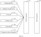
- the driving behavior monitoring system includes the terminal apparatus according to the third aspect, and includes an imaging apparatus, a gyroscope, a visibility sensor, a sweat detector, and/or a fingerprint collection apparatus.
- a state threshold for identifying a current driving behavior is determined according to a state threshold determining parameter of the driving behavior, a state evaluation value of the driving behavior is determined according to a state parameter of a driver in a driving process, and a type of the driving behavior is then determined according to the evaluation value and the state threshold of the driving behavior. Therefore, by using the solutions provided by embodiments of this application, it can be determined whether the driving behavior is an improper driving behavior.
- a state threshold of a driving behavior is related to a state threshold determining parameter of the driving behavior.
- the state threshold of the driving behavior also changes correspondingly. Therefore, a state threshold of the driving behavior determined in embodiments of this application better conforms to a current driving behavior monitoring scenario. Compared with a solution using a fixed threshold, in this application, the accuracy of driving behavior monitoring can be effectively improved.
- A/B may represent A or B.
- and/or describes only an association relationship for describing associated objects and represents that three relationships may exist.
- a and/or B may represent the following three cases: Only A exists, both A and B exist, and only B exists.
- a plurality of means two or more.
- an image of a driver is collected by a camera, and the image is analyzed to determine a blinking frequency, a mouth opening frequency, and the like of the driver, which are then compared with preset frequency thresholds. It is determined whether the driver has improper driving behaviors according to comparison results.
- the blinking frequency of the driver may be compared with a preset blinking frequency threshold. If the blinking frequency is greater than the preset blinking frequency threshold, it may be determined that the driving behavior of the driver is improper.
- a frequency threshold is usually fixed, and the driver has different facial expression change frequencies in different states. For example, the driver has different facial expression change frequencies when being relaxed and nervous.
- drivers with different personalities have different facial expression change frequencies.
- extroverted and introverted drivers have different facial expression change frequencies in the same scenario. Therefore, determining whether a driving behavior is improper by using a fixed frequency threshold usually has low accuracy, and even causes misjudgment of the driving behavior.
- physiological data of a driver for example, pulse, blood pressure, or body temperature
- a smart band worn by the driver is collected by using a smart band worn by the driver.
- the physiological data is compared with a preset physiological threshold. Then it is determined, according to a comparison result, whether the driver has improper driving behaviors.
- the pulse of the driver may be compared with a preset pulse threshold. If the pulse of the driver is greater than the pulse threshold, it may be determined that the driving behavior of the driver is improper.
- a physiological threshold is fixed, and drivers usually have different physiological data in different states of health. Determining whether the driving behavior is improper by using the fixed physiological threshold usually has low accuracy, and even causes misjudgment of the driving behavior.
- embodiments of this application provide a driving behavior monitoring method.
- the method is usually applied to a driving behavior monitoring apparatus.
- the driving behavior monitoring apparatus may be installed in a vehicle, and monitors a driving behavior of a driver according to the solutions provided by embodiments of this application in a running process of the vehicle.
- the driving behavior monitoring apparatus may be disposed in a remote computer.
- the remote computer may obtain a state parameter of the driver in a driving process, and monitor the driving behavior based on the state parameter and according to the solutions provided by embodiments of this application.
- the driving behavior monitoring apparatus may alternatively be in another form. This is not limited in embodiments of this application.
- the driving behavior monitoring apparatus is usually equipped with a built-in processor.
- the processor may obtain a state parameter and a threshold determining parameter that are transmitted by a sensor, or the processor may determine a corresponding state parameter and threshold determining parameter according to information transmitted by the sensor, and determine a type of the driving behavior according to the state parameter and the threshold determining parameter.
- the driving behavior monitoring apparatus When the driving behavior monitoring apparatus is installed in a vehicle, the driving behavior monitoring apparatus may be an in-vehicle terminal of the vehicle.
- the processor is a built-in processor of the in-vehicle terminal.
- the senor may be disposed in the driving behavior monitoring apparatus, and is connected to the processor in the driving behavior monitoring apparatus.
- the senor may be a component independent of the driving behavior monitoring apparatus. After detecting corresponding information, the sensor may transmit the information to the processor, so that the processor determines the state parameter of the driver in the driving process, determines the state threshold determining parameter of the driving behavior, and determines the type of the driving behavior according to the solutions provided by embodiments of this application.
- an interface for exchanging data with the sensor is disposed in the processor. By using the interface, the processor may obtain the information transmitted by the sensor.
- a driving behavior monitoring method provided by embodiments of this application includes the following steps.
- Step S11 Determine a state evaluation value of a driving behavior according to a state parameter of a driver in a driving process.
- the state parameter usually includes at least one type, and the state parameter may be used to reflect a facial expression and/or physiological information of the driver, and the like.
- the state parameter of the driver may be periodically collected, and the state evaluation value of the driving behavior in each period is determined according to the state parameter.
- Step S12 Determine a state threshold of the driving behavior according to a state threshold determining parameter of the driving behavior.
- the threshold determining parameter may include at least one type.
- the corresponding state threshold may be determined according to the state threshold determining parameter of the driving behavior. Therefore, the threshold is not fixed.
- Step S13 Determine a type of the driving behavior according to the state evaluation value of the driving behavior and the state threshold of the driving behavior.
- the state parameter of the driver may also be periodically collected, and the state evaluation value of the driving behavior in each period is determined according to the state parameter.
- the type of the driving behavior may be classified into an improper driving behavior and a normal driving behavior, or the type of the driving behavior may be further subdivided.
- the state threshold of the driving behavior is determined.
- the state threshold of the driving behavior may be first determined according to the state threshold determining parameter of the driving behavior, the state evaluation value of the driving behavior is then determined according to the state parameter of the driver in the driving process, or both the state evaluation value and threshold of the driving behavior may be determined. This is not limited in embodiments of this application.
- a time difference between a determining time point of the state evaluation value of the driving behavior and a determining time point of the state threshold of the driving behavior is usually within a specific time range. If the two times are closer, the type of the driving behavior determined in step S13 is usually more accurate.
- the driving behavior monitoring method provided by embodiments of this application includes: determining, according to a state threshold determining parameter of a driving behavior, a state threshold for identifying the current driving behavior; determining a state evaluation value of the driving behavior according to a state parameter of a driver in a driving process; and determining a type of the driving behavior according to the evaluation value and the state threshold of the driving behavior. Therefore, according to the solutions provided by embodiments of this application, it can be determined whether the driving behavior is an improper driving behavior.
- a state threshold of a driving behavior is related to a state threshold determining parameter of the driving behavior.
- the state threshold of the driving behavior also changes correspondingly. Therefore, a state threshold of the driving behavior determined in embodiments of this application better conforms to a current driving behavior monitoring scenario. Compared with a solution using a fixed threshold, in this application, accuracy of driving behavior monitoring can be effectively improved.
- the state evaluation value of the driving behavior is determined based on the state parameter of the driver in the driving process.
- the state parameter may include: a facial expression parameter and/or a physiological information parameter.
- the facial expression parameter includes: a quantity of times of opening and closing eyes per unit time and/or a quantity of times of opening and closing the mouth per unit time.
- the facial expression parameter may be obtained by using an imaging apparatus that shoots an image of the driver.
- the imaging apparatus may include a camera and/or a video camera.
- the camera may be a driver monitor system (driver monitor system, DMS) camera.
- the imaging apparatus may transmit the image to a driving behavior apparatus that executes the solutions in embodiments of this application.
- the driving behavior apparatus analyzes the image, and determines the facial expression parameter according to an image analysis result.
- the imaging apparatus may analyze the image to determine the facial expression parameter of the driver, and then transmit the facial expression parameter to the driving behavior monitoring apparatus, so that the driving behavior monitoring apparatus obtains the facial expression parameter.
- the imaging apparatus may be connected to the apparatus for performing the driving behavior monitoring method provided by embodiments of this application by using a serializer/deserializer.
- the physiological information parameter includes at least one of the following parameters: a quantity of pulses per unit time, a heart rate, blood pressure, and body temperature.
- the physiological information parameter may be obtained by using an intelligent wearable device of the driver.
- the intelligent wearable device includes a plurality of types, for example, a smartwatch, a smart band, and the like. After the driver wears the intelligent wearable device, the intelligent wearable device may collect physiological information of the driver, and transmit the physiological information to the driving behavior apparatus that executes the solutions in embodiments of this application.
- a time difference between a determining time point of the state parameter and a determining time point of the assessment value is less than a first time period.
- Specific duration of the first time period may be set according to a driving behavior monitoring requirement. Generally, a higher accuracy requirement for driving behavior monitoring indicates shorter specific duration of the first time period. For example, the first time period may be 1 minute.
- the state parameter used to monitor the driving behavior may include both the facial expression parameter and the physiological information parameter.
- information to which the solutions provided by embodiments of this application are applied is more diversified. Therefore, the accuracy of driving behavior monitoring can be further improved.
- the reference value of the i th state parameter is the i th state parameter of the driver in a normal driving process.
- the driving behavior of the driver usually includes the normal driving behavior and the improper driving behavior, and the reference value of the state parameter is a state parameter determined by the driver in the normal driving process.
- state parameters of the driver in the normal driving process in different environments may be collected for a plurality of times in advance, and an average value of the state parameters collected for the plurality of times is calculated.
- the average value of the state parameters may be the reference value of the state parameters.
- the state parameter of the driver may be determined by using the imaging apparatus and/or the intelligent wearable device, and then the reference value and the state parameter are substituted into Formula (1), so as to obtain the state evaluation value of the driving behavior through calculation.
- the reference value of the state parameter may be the average value of the state parameters when the driver performs normal driving in different environments.
- the different environments may include different weather, places of different steepness degrees, places of different density degrees, and/or the like. This is not limited in embodiments of this application.
- the state parameter includes blood pressure
- blood pressure of the driver during normal driving in different environments may be collected for a plurality of times in advance, and then an average value of the collected blood pressure is calculated.
- the average value of the blood pressure is a reference value of the blood pressure.
- the state evaluation value of the driving behavior is determined by using n 1 state parameters, where n 1 is a positive integer.
- n 1 is 5, and the five state parameters are respectively a quantity of times of opening and closing eyes per unit time, a quantity of times of opening and closing the mouth per unit time, a quantity of pulses per unit time, a heart rate, blood pressure, and body temperature.
- an operation of determining a state threshold of the driving behavior according to a state threshold determining parameter of the driving behavior is further provided.
- the threshold determining parameter includes at least one of the following parameters: a danger coefficient of a location of the driver, a fatigue degree coefficient of the driver, a density degree coefficient of the location of the driver, or a danger coefficient of an environment in which the driver is located.
- the vehicle travels to different locations, and danger coefficients of different locations are usually different.
- a location with a higher danger coefficient is more likely to have a traffic accident.
- traffic accidents often occur at crossroads, and the danger coefficient is high.
- the danger coefficient of the location of the driver is one of the threshold determining parameters.
- the fatigue degree coefficient of the driver is one of the threshold determining parameters.
- the density degree of the location of the driver also affects occurrence of traffic accidents. Generally, a denser location indicates a higher probability of occurrence of traffic accidents. Therefore, the density degree of the location of the driver may also be used as one of the threshold determining parameters.
- the danger coefficient of an environment in which the driver is located is usually related to visibility of the environment, a road steepness, and the like.
- a higher danger coefficient in an environment indicates a higher probability of traffic accidents in the environment. Therefore, the danger coefficient of the environment in which the driver is located may be further used as one of the threshold determining parameters.
- threshold determining parameter another type of parameter may be used as the threshold determining parameter. This is not limited in embodiments of this application.
- a time difference between a determining time point of the threshold determining parameter and a determining time point of the state threshold of the driving behavior is less than a second time period.
- the state threshold of the driving behavior is usually closer to an actual driving scenario.
- Specific duration of the second time period may be set according to a driving behavior monitoring requirement. Generally, a higher accuracy requirement for driving behavior monitoring indicates shorter specific duration of the second time period.
- the first time period and the second time period may be the same or may be different. This is not limited in embodiments of this application. For example, the second time period may also be 1 minute.
- the danger coefficient of the location of the driver is usually related to the probability that the traffic accident occurs at the location, the danger coefficient of the traffic accident, and the vehicle speed in the driving process.
- the danger coefficient of the location of the driver may be determined by using Formula (2).
- a probability that a traffic accident occurs at each location on a map may be determined in advance with reference to the map and big data analysis.
- the probability that the traffic accident occurs at each location may be determined by querying a record of a traffic management center.
- the probability of accidents at each location may alternatively be determined in another manner. This is not limited in embodiments of this application.
- the location of the driver may be determined according to a global positioning system (global positioning system, GPS).
- GPS global positioning system
- the GPS may be connected to the driving behavior monitoring apparatus for performing the method in embodiments of this application, or the GPS is built in the driving behavior monitoring apparatus.
- a probability that various traffic accidents occur at the location of the driver is determined according to the location of the driver and the previously determined probability that the traffic accident occurs at each location, and the target traffic accident having a probability of occurrence greater than the first probability is further determined.
- a correspondence between different traffic accidents and danger coefficients may be set.
- the danger coefficient of the target traffic accident may be determined according to the correspondence.
- the traffic accident may be divided into a minor accident, a general accident, a major accident, and an extra serious accident according to a consequence caused by the traffic accident.
- the minor accident refers to an accident in which one to two people are slightly injured at a time, or an amount of property loss caused by a motor vehicle accident is less than 1000 yuan and an amount of property loss caused by a non-motor vehicle accident is less than 200 yuan.
- the general accident refers to an accident in which one to two people are seriously injured at a time, or more than three people are slightly injured, or an amount of property loss is less than 30,000 yuan.
- the major accident refers to an accident in which one to two people are killed at a time, or more than three and less than 10 people are seriously injured, or an amount of property loss is more than 30,000 yuan and less than 60,000 yuan.
- the extra serious accident refers to an accident in which more than three people are killed at a time, or more than 11 people are seriously injured, or one person is killed while more than eight people are seriously injured, or two people are killed while more than five people are seriously injured, or an amount of property loss is more than 60,000 yuan.
- danger coefficients corresponding to the minor accident, the general accident, the major accident, and the extra serious accident may be set to ⁇ 1 , ⁇ 2, ⁇ 3, and ⁇ 4 respectively, where ⁇ 1, ⁇ 2 , ⁇ 3 , and ⁇ 4 are positive numbers in ascending order.
- ⁇ 1 may be set to 0.1
- ⁇ 2 may be set to 0.2
- ⁇ 3 may be set to 0.3
- ⁇ 4 may be set to 0.4.
- the types of the traffic accidents may be further divided in another manner, and the danger coefficients corresponding to the traffic accidents of various types are separately set. This is not limited in embodiments of this application.
- the probability of occurrence and the danger coefficient of the target traffic accident are substituted into Formula (2), so that the danger coefficient of the location of the driver may be determined accordingly.
- the threshold determining parameter may further include the fatigue degree coefficient of the driver.
- the fatigue degree of the driver is usually related to driving duration.
- longer driving duration indicates more fatigue of the driver.
- the first time length may be set, and the first time length is usually a maximum time length in which the driver can maintain the normal driving behavior.
- the driving duration of the driver is less than the first time length, the fatigue degree of the driver increases as the driving duration increases.
- the driving duration of the driver reaches the first time length, the driver usually reaches a relatively high fatigue degree, and after the driving duration exceeds the first time length, the driving behavior of the driver is usually a fatigue driving behavior.
- the first time length may be set to 4 hours.
- the density degree coefficient of the location of the driver is related to a quantity of pedestrians and a quantity of vehicles around the location. Therefore, in embodiments of this application, the density degree coefficient is determined by using a sum of the quantity of pedestrians and the quantity of vehicles at the location of the driver in a specific range.
- the imaging apparatus may obtain a surrounding image of the location of the driver, and transmit the surrounding image to the apparatus for performing the driving behavior monitoring method in embodiments of this application.
- the apparatus may determine, by analyzing the surrounding image, quantities of pedestrians and vehicles in a specific range from the location of the driver.
- a 1, a 2, and a 3 are positive numbers, and are respectively used to represent coefficients indicating that the quantities of pedestrians and vehicles in the first range, the second range, and the third range are related to the density degree, where a range closer to the location of the driver usually has a larger coefficient.
- the first range is set to a distance within 30 meters from the location of the driver
- the second range is set to a distance within 30 meters to 80 meters from the location of the driver
- the third range is set to a distance beyond 80 meters from the location of the driver, where a 1 may be set to 0.5, a 2 may be set to 0.3, and a 3 may be set to 0.2.
- D is a ground steepness degree of the location of the driver
- ⁇ is an angle between a body of a vehicle in which the driver is located and a horizontal plane
- g is a the highest level of visibility level
- S is a visibility level of the environment in which the driver is located
- a 4 and a 5 are positive numbers.
- the danger coefficient of the environment in which the driver is located is often related to the ground steepness degree of the environment and the visibility of the environment. A higher ground steepness degree of the environment indicates a steeper ground, and correspondingly, the environment is more dangerous for the driving behavior.
- the visibility of the environment in which the driver is located varies according to the weather and time.
- a lower visibility of the environment in which the driver is located indicates a lower probability that the driver avoids an obstacle in the driving process. Therefore, a lower visibility of the environment indicates a more dangerous environment for the driving behavior.
- the ground steepness degree of the location of the driver may be determined by using Formula (5).
- the angle ⁇ between the body and the horizontal plane may be determined by using a gyroscope disposed on the vehicle.
- the gyroscope may transmit the detected angle ⁇ to the driving behavior monitoring apparatus provided by embodiments of this application, and then the driving behavior monitoring apparatus substitutes the obtained angle ⁇ into Formula (5), so as to determine the ground steepness degree D of the location of the driver.
- the gyroscope may be a three-axis gyroscope.
- visibility levels respectively corresponding to a plurality of visibility ranges may be further set, and a visibility range of the environment in which the driver is located is determined by using a visibility sensor.
- the visibility sensor transmits the detected visibility to the driving behavior monitoring apparatus provided by embodiments of this application.
- the driving behavior monitoring apparatus determines a visibility level of the environment in which the driver is located according to the visibility range to which the obtained visibility belongs.
- the visibility sensor may be disposed outside the vehicle, or the visibility sensor may be disposed around an intersection through which the vehicle passes, for example, may be disposed on a railing of the intersection through which the vehicle passes.
- a 4 and a 5 are respectively a proportion of the visibility level of the environment in which the driver is located in the danger coefficient of the environment, and a proportion of the ground steepness degree of the environment in which the driver is located in the danger coefficient of the environment.
- both a 4 and a 5 are set to 0.5, and a total quantity of levels of the specified visibility level is 9.
- the state threshold of the driving behavior may be determined by using the state threshold determining parameter.
- At least one type of threshold determining parameter may be included, and the state threshold of the driving behavior is determined by using the at least one type of threshold determining parameter.
- the state threshold of the driving behavior is determined by using n 3 types of threshold determining parameters.
- the threshold determining parameters are not fixed, but may be correspondingly adjusted based on an actual situation of the driving process, so that the state threshold of the driving behavior determined according to the threshold determining parameters is closer to an actual driving scenario, thereby further improving the accuracy of driving behavior monitoring.
- the n3 types of threshold determining parameters may include the danger coefficient of the location of the driver. It can be learned from the foregoing description that, when the danger coefficient of the location of the driver is determined, the danger coefficient of the traffic accident that is prone to occur at the location of the driver and the vehicle speed in the driving process are considered. Therefore, the state threshold of the driving behavior determined based on the danger coefficient of the location of the driver can change with the danger coefficient and the vehicle speed of the traffic accident that is prone to occur.
- the n3 types of threshold determining parameters may include the fatigue degree coefficient of the driver. It can be learned from the foregoing description that driving duration of the driver is considered when the fatigue degree coefficient of the driver is determined. In this case, the state threshold of the driving behavior determined based on the fatigue degree coefficient of the driver can change with the driving duration of the driver.
- the n3 types of threshold determining parameters may further include the density degree coefficient of the location of the driver. It can be learned from the foregoing description that when the density degree coefficient of the location of the driver is determined, quantities of vehicles and pedestrians around the location of the driver are considered. Therefore, the state threshold of the driving behavior determined based on the density degree coefficient can change with the quantities of vehicles and pedestrians around the location of the driver.
- the n3 types of threshold determining parameters may further include the danger coefficient of the environment in which the driver is located.
- the danger coefficient of the environment in which the driver is located is determined, the visibility level of the environment in which the driver is located and the ground steepness degree of the location of the vehicle are considered.
- the state threshold of the driving behavior determined based on the danger coefficient of the environment in which the driver is located can change with the visibility level of the environment and the ground steepness degree.
- the state threshold of the driving behavior is determined by using the solutions in embodiments of this application, elements that affect the driving behavior in an actual driving scenario are considered, so that the state threshold of the driving behavior can better comply with the actual driving scenario, a monitoring requirement of driving behavior monitoring is met, and the accuracy of driving behavior monitoring is improved.
- a threshold used to determine whether the driving behavior is the improper driving behavior is usually fixed. If the threshold is relatively high, the driver always needs to maintain relatively high attention to maintain the normal driving behavior. The driver is always in a mentally tight state, and fatigue driving is more likely to occur, thereby resulting in a violation of the wish. However, if the threshold is relatively low, the improper driving behavior may be determined as the normal driving behavior, thereby increasing a probability of reducing monitoring accuracy.
- the state threshold determined in the solutions provided by embodiments of this application may be adjusted with the actual driving scenario, so that monitoring accuracy can be improved, and the driver can be prevented from being always in the mentally tight state, thereby effectively relieving fatigue of the driver.
- operations of determining the state evaluation value of the driving behavior and the state threshold of the driving behavior are separately provided.
- the type of the driving behavior may be further determined according to the state evaluation value of the driving behavior and the state threshold of the driving behavior.
- the determining a type of the driving behavior according to the state evaluation value of the driving behavior and the state threshold of the driving behavior usually includes the following steps.
- a state target value of the normal driving behavior is determined according to a reference value of a normal driving behavior and the state threshold of the driving behavior.
- the driving behavior is determined according to a comparison result between the state evaluation value of the driving behavior and the state target value of the normal driving behavior.
- the reference value of the normal driving behavior is usually determined based on the reference value of each state parameter.
- w reference is the reference value of the normal driving behavior
- n 4 is a quantity of state parameters for calculating the reference value of the normal driving behavior
- C ⁇ 0 is a reference value of the ⁇ th state parameter
- C ⁇ is a minimum value of the ⁇ th state parameter when a normal driving state is maintained
- ⁇ and n 4 are both positive integers
- the minimum value of the ⁇ th state parameter may be a maximum value of the ⁇ th state parameter.
- values required by the same state parameter are usually different. For example, when driving in an area with a stable ground and a low population flow, a heart rate of the driver during the normal driving is relatively low, and when driving in an area with a steep ground and a dense population flow, the heart rate of the driver during the normal driving is relatively high. In this case, a minimum value of the heart rate is a maximum value of the heart rate of the driver during the normal driving.
- the driving behavior may be divided into a normal driving behavior and an improper driving behavior.
- the driving behavior may be considered as the normal driving behavior.
- the driving behavior may be considered as the improper driving behavior.
- the state parameter for calculating the reference value of the normal driving behavior is set to the heart rate, and the reference value of the heart rate is 100.
- the minimum value of the heart rate is 120.
- the state threshold V of the driving behavior is set to 20%
- the improper driving behavior may be further subdivided.
- the improper driving behavior may be divided into a driving behavior indicating that the driver is in an abnormal driving state but has a driving ability and a driving behavior indicating that the driver is in an abnormal driving state and does not have a driving ability.
- the driving behavior may be divided into three types: a normal driving behavior, a driving behavior indicating that the driver is in an abnormal driving state but has a driving ability, and a driving behavior indicating that the driver is in an abnormal driving state and does not have a driving ability.
- the determining the driving behavior according to a comparison result between the state evaluation value of the driving behavior and the state target value of the normal driving behavior includes:
- the first threshold is not less than 0, and the second threshold is a negative number.
- the first threshold is not less than 0. If the difference between the state evaluation value of the driving behavior and the state target value of the normal driving behavior is greater than the first threshold, it indicates that the state evaluation value of the driving behavior is greater than the state target value of the normal driving behavior. In this case, it may be determined that the driving behavior is the normal driving behavior.
- the second threshold is a negative number. If the difference between the state evaluation value of the driving behavior and the state target value of the normal driving behavior is greater than the second threshold and is not greater than the first threshold, it indicates that the state evaluation value of the driving behavior is relatively close to the state target value of the normal driving behavior. In this case, it may be determined that the driving behavior indicates that the driver is in an abnormal driving state but has a driving ability.
- the state evaluation value of the driving behavior is relatively small compared with the state target value of the normal driving behavior. In this case, it may be usually determined that the driving behavior indicates that the driver is in an abnormal driving state and does not have a driving ability.
- the type of the driving behavior can be determined according to a comparison result between the state evaluation value of the driving behavior and the state target value of the normal driving behavior.
- the state evaluation value of the driving behavior is compared with the state target value of the normal driving behavior, and the state target value of the normal driving behavior changes with the state threshold of the driving behavior.
- the state threshold used to determine whether the driving behavior is the normal driving behavior is always adjusted. Therefore, in different driving scenarios, if the normal driving behavior is maintained, the driver may be in different states. Compared with a driving scenario with a relatively large state threshold, a driving scenario with a relatively small state threshold requires less attention of the driver to maintain the normal driving behavior.
- the driver adjusts a driving state according to an actual driving scenario.
- attention of the driver with the normal driving behavior may be slightly reduced, so that the driver feels less exhausted.
- the attention of the driver with the normal driving behavior needs to be improved, thereby reducing occurrence of a traffic accident and improving driving safety.
- FIG. 2 is a schematic diagram of a state evaluation value of a driving behavior and a state target value of a normal driving behavior.
- a horizontal axis represents driving times
- a solid line represents state evaluation values of driving behaviors at different driving times
- a dashed line represents state target values of normal driving behaviors at different driving times
- an arrow indicates that the driver needs to adjust the driving state.
- the state target values of the normal driving behavior are also different due to different state thresholds of the driving behaviors.
- the first threshold is set to 0. If the state evaluation value of the driving behavior is greater than the state target value of the normal driving behavior, the driving behavior is the normal driving behavior. If the evaluation value of the driving behavior is not greater than the state target value of the normal driving behavior, the driving behavior is the improper driving behavior.
- the driver may be alerted to adjust the driving state, so as to enter a normal driving state.
- the state evaluation value of the driving behavior may also change accordingly.
- the state of the driver may be properly adjusted, so that the driver can be prevented from being always in a mentally tight state while the normal driving behavior is ensured, thereby reducing a fatigue driving state of the driver and improving traffic safety.
- the following operations may further be included:
- the driver may be alerted in embodiments of this application.
- multi-level information alerting may be performed. For example, an initial alert is a low-sound speech alert. If the state of the driver does not change after a plurality of speech alerts, a alert frequency and alert volume may be increased. In addition, the intelligent wearable device may be touched to vibrate intermittently. If the state of the driver does not change in this case, alert strength may continue to be increased until an engine shuts off, and the driving behavior is terminated.
- the vehicle is parked on a roadside, and the current driving behavior is terminated.
- the vehicle After being parked on the roadside, the vehicle may be controlled to turn on an emergency flasher, and a medical emergency center or a traffic police center may be contacted.
- a medical emergency center or a traffic police center may be contacted.
- the driver presets contact information of an emergency contact in the apparatus for performing the driving behavior monitoring method provided by embodiments of this application, the driver may further contact the emergency contact.
- positioning information may be further sent to the emergency contact, the medical emergency center, or the traffic police center
- physiological data such as a real-time thermal imaging image, a pulse, blood pressure, and body temperature may be transmitted to the medical emergency center or the traffic police center, and a call function of the intelligent wearable device is enabled.
- the in-vehicle terminal after it is determined that the driving behavior is the improper driving behavior, the in-vehicle terminal usually sends alarm information to report an alarm to 110, thereby wasting a large quantity of police resources.
- the improper driving behavior may be subdivided.
- the improper driving behavior may be divided into the driving behavior indicating that the driver is in an abnormal driving state but has a driving ability and the driving behavior indicating that the driver is in an abnormal driving state and does not have a driving ability.
- different alerting solutions are used to implement hierarchical alerts of the improper driving behavior. Compared with the conventional technology, the solutions in this application avoid a waste of police resources.
- solutions provided by embodiments of this application further include the following step: when determining, by using a sweat detector, that an alcohol content in sweat of the driver is less than a first content, triggering the vehicle to start.
- the alcohol content in the sweat of the driver is not less than the first content, it is generally considered that the driver is driving after being intoxicated (that is, in drunk driving). In this case, to improve traffic safety, the start of the vehicle is usually suspended. If the alcohol content in the sweat of the driver is less than the first content, it may be considered that the driver is not in drunk driving, and the vehicle may be triggered to start.
- the sweat detector may be disposed on a side, close to the skin of the driver, of the intelligent wearable device worn by the driver.
- the intelligent wearable device may be a smartwatch
- the sweat detector may be disposed on a back of a watch face of the smartwatch.
- the intelligent wearable device may be a smart band
- the sweat detector may be disposed on a side, close to a wrist, of the smart band.
- the intelligent wearable device provided with the sweat detector and the intelligent wearable device that obtains the physiological information parameter of the driver may be the same intelligent wearable device, or may be different intelligent wearable devices. This is not limited in embodiments of this application.
- the sweat detector may be further disposed at a position on the vehicle.
- the sweat detector disposed at the position may detect the alcohol content in the sweat of the driver.
- the sweat detector may be disposed on a steering wheel of the vehicle.
- the sweat detector may include: a sweat collection unit, an alcohol sensor, an analog-to-electrical converter, and a microcontroller unit (microcontroller unit, MCU).
- the sweat collection unit may be made of a material such as paper, a polymer fiber, or a hydrogel, and is configured to collect the sweat of the driver.
- the alcohol sensor and the analog-to-electrical converter quantize the alcohol content included in the sweat, and transmit a quantization result to the MCU.
- the MCU determines, according to the quantization result, whether the alcohol content in the sweat of the driver is less than the first content, and transmits the determined result to the apparatus for performing the driving behavior monitoring method provided by embodiments of this application.
- the apparatus controls the vehicle to suspend starting.
- the apparatus that performs the driving behavior monitoring method provided by embodiments of this application may allow the vehicle to start.
- the sweat detector may include: a sweat collection unit, an alcohol sensor, and an analog-to-electrical converter.
- the sweat collection unit collects the sweat of the driver.
- the alcohol sensor and the analog-to-electrical converter quantize the alcohol content included in the sweat, and transmit a quantization result to the apparatus for performing the driving behavior monitoring method provided by embodiments of this application.
- the apparatus determines, according to the quantization result, whether the alcohol content in the sweat of the driver is less than the first content. If the alcohol content in the sweat of the driver is less than the first content, the apparatus allows the vehicle to start. If the alcohol content in the sweat of the driver is not less than the first content, the apparatus suspends the start of the vehicle.
- the smart band worn by the driver may collect gas exhaled by the driver, determine the alcohol content in the gas by analyzing the gas, and further determine whether the driver is in drunk driving.
- the vehicle is triggered to start only when it is determined that the alcohol content in the sweat of the driver is less than the first content. However, if it is determined that the alcohol content in the sweat of the driver is not less than the first content, the vehicle is not allowed to start. Therefore, compared with the conventional technology, drunk driving can be avoided, and road traffic safety is further improved.
- the method may further include the following step: when a fingerprint of the driver matches a stored fingerprint library, triggering the vehicle to start.
- the fingerprint library stores a pre-collected fingerprint of at least one driver. That the fingerprint of the driver matches the fingerprint library means that the fingerprint of the driver and a fingerprint in the fingerprint library are fingerprints of a same person.
- Identity authentication of the driver can be implemented through fingerprint matching, so that only the driver whose fingerprint is collected in advance and stored in the fingerprint library is allowed to drive the vehicle, thereby further improving traffic safety.
- a fingerprint collection apparatus may be disposed on the intelligent wearable device of the driver or the vehicle.
- the fingerprint collection apparatus may collect the fingerprint of the driver, and transmit the collected fingerprint to the apparatus that performs the driving behavior monitoring method provided by embodiments of this application.
- the apparatus then matches and compares the fingerprint with the fingerprint library, so as to determine whether the fingerprint of the driver matches the fingerprint library.
- the fingerprint matching apparatus may be disposed on the intelligent wearable device of the driver or the vehicle, and the fingerprint matching apparatus includes the fingerprint library.
- the fingerprint matching apparatus may collect the fingerprint of the driver, match the collected fingerprint with the fingerprint library, and transmit a matching result to the apparatus that performs the driving behavior monitoring method provided by embodiments of this application.
- the apparatus determines, according to the received matching result, whether to trigger the vehicle to start.
- the solutions in which the start of the vehicle is triggered only when the alcohol content in the sweat of the driver is less than the first content and the fingerprint of the driver matches the fingerprint library are separately provided.
- the vehicle may be triggered to start only when both the two conditions are met, thereby further improving the traffic safety.
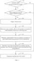
- FIG. 3 Referring to a schematic diagram of a working procedure shown in FIG. 3 , the method includes the following steps.
- Step S21 Determine, by using a sweat detector, whether an alcohol content in sweat of a driver is less than a first content; and if the alcohol content in the sweat of the driver is less than the first content, perform an operation of step S22, or if the alcohol content in the sweat of the driver is not less than the first content, perform an operation of step S27.
- the sweat detector fits the skin of the driver, and may collect sweat on the skin of the driver, quantize the alcohol content included in the sweat, and transmit a quantization result to the apparatus for performing the driving behavior monitoring method provided by embodiments of this application.
- the apparatus determines, according to the quantization result, whether the alcohol content in the sweat of the driver is less than the first content.
- the sweat detector may determine, according to the collected sweat, whether the alcohol content in the sweat is less than the first content, and transmit a determining result to the apparatus for performing the driving behavior monitoring method provided by embodiments of this application.
- Step S22 Determine whether a fingerprint of the driver matches a stored fingerprint library; and if the fingerprint of the driver matches the stored fingerprint library, perform an operation of step S23, or if the fingerprint of the driver does not match the stored fingerprint library, perform an operation of step S27.
- the fingerprint library stores a pre-collected fingerprint of at least one driver. Identity authentication of the driver can be implemented through fingerprint matching.
- Step S23 Trigger a vehicle to start, so that the driver drives the vehicle.
- the vehicle is started only after it is determined, by performing operations in step S21 and step S22, that the driver is not in drunk driving and an identity of the driver is authenticated.
- Step S24 Determine a state evaluation value of a driving behavior according to a state parameter of the driver in a driving process.
- Step S25 Determine a state threshold of the driving behavior according to a state threshold determining parameter of the driving behavior.
- Step S26 Determine a type of the driving behavior according to the state evaluation value of the driving behavior and the state threshold of the driving behavior.
- step S24 to step S26 is the same as a specific operation process of step S11 to step S13. Mutual reference may be made, and details are not described herein again.
- Step S27 Temporarily terminate start of the vehicle.
- the vehicle can be started only when both the condition that the alcohol content in the sweat of the driver is less than the first content and the condition that the fingerprint of the driver matches the stored fingerprint library are met, so that traffic safety can be further improved.
- embodiments of this application disclose a driving behavior monitoring apparatus.
- the driving behavior monitoring apparatus disclosed by embodiments of this application includes: a processor 110, a first transceiver interface 120, and a second transceiver interface 130.
- the first transceiver interface 120 is configured to obtain a state parameter of a driver in a driving process.
- the second transceiver interface 130 is configured to obtain a state threshold determining parameter of a driving behavior.
- the processor 110 is configured to determine a state evaluation value of the driving behavior according to the state parameter of the driver in the driving process, and determine a state threshold of the driving behavior according to the state threshold determining parameter of the driving behavior.
- the processor 110 is further configured to determine a type of the driving behavior according to the state evaluation value of the driving behavior and the state threshold of the driving behavior.
- a state threshold for identifying a current driving behavior can be determined according to a state threshold determining parameter of the driving behavior, a state evaluation value of the driving behavior can be determined according to a state parameter of a driver in a driving process, and a type of the driving behavior can be then determined according to the evaluation value and the state threshold of the driving behavior. Therefore, according to the solutions provided by embodiments of this application, it can be determined whether the driving behavior is an improper driving behavior.
- a state threshold of a driving behavior is related to a state threshold determining parameter of the driving behavior.
- the state threshold of the driving behavior also changes correspondingly. Therefore, a state threshold of the driving behavior determined in embodiments of this application better conforms to a current driving behavior monitoring scenario. Compared with a solution using a fixed threshold, in this application, accuracy of driving behavior monitoring can be effectively improved.
- the state parameter usually includes at least one type, and the state parameter may be used to reflect a facial expression and/or physiological information of the driver, and the like.
- the state parameter includes: a facial expression parameter and/or a physiological information parameter.
- the facial expression parameter includes: a quantity of times of opening and closing eyes per unit time and/or a quantity of times of opening and closing the mouth per unit time.
- the physiological information parameter includes at least one of the following parameters: a quantity of pulses per unit time, a heart rate, blood pressure, and body temperature.
- a time difference between a determining time point of the state parameter and a determining time point of the evaluation value is less than a first time period.
- the facial expression parameter is obtained by using an imaging apparatus that shoots an image of the driver.
- the physiological information parameter is obtained by using an intelligent wearable device of the driver.
- the first transceiver interface 120 may be separately connected to the imaging apparatus and/or the intelligent wearable device, so as to obtain the facial expression parameter and/or the physiological information parameter.
- the threshold determining parameter may include at least one type.
- the threshold determining parameter includes at least one of the following parameters: a danger coefficient of a location of the driver, a fatigue degree coefficient of the driver, a density degree coefficient of the location of the driver, or a danger coefficient of an environment in which the driver is located.
- a time difference between a determining time point of the threshold determining parameter and a determining time point of the state threshold of the driving behavior is less than a second time period.
- the processor is specifically configured to: determine a state target value of the normal driving behavior according to a reference value of a normal driving behavior and the state threshold of the driving behavior; and determine the driving behavior according to a comparison result between the state evaluation value of the driving behavior and the state target value of the normal driving behavior.
- the driving behavior may be divided into a normal driving behavior and an improper driving behavior.
- the driving behavior may be considered as the normal driving behavior.
- the driving behavior may be considered as the improper driving behavior.
- the improper driving behavior may be further subdivided.
- the improper driving behavior may be divided into a driving behavior indicating that the driver is in an abnormal driving state but has a driving ability and a driving behavior indicating that the driver is in an abnormal driving state and does not have a driving ability.
- the driving behavior may be divided into three types: a normal driving behavior, a driving behavior indicating that the driver is in an abnormal driving state but has a driving ability, and a driving behavior indicating that the driver is in an abnormal driving state and does not have a driving ability.
- the processor may divide the driving behavior in the following manners.
- the processor determines that the driving behavior is the normal driving behavior.
- the processor determines that the driving behavior indicates that the driver is in an abnormal driving state but has a driving ability.
- the processor determines that the driving behavior indicates that the driver is in an abnormal driving state and does not have a driving ability.
- the first threshold is not less than 0, and the second threshold is a negative number.
- the type of the driving behavior can be determined according to a comparison result between the state evaluation value of the driving behavior and the state target value of the normal driving behavior.
- the processor is further configured to alert the driver when the type of the driving behavior indicates that the driver is in an abnormal driving state but has a driving ability, and park the vehicle on a roadside when the driving behavior indicates that the driver is in an abnormal driving state and does not have a driving ability.
- the processor is further configured to: when determining, by using a sweat detector, that an alcohol content in sweat of the driver is less than a first content, trigger the vehicle to start.
- the processor is further configured to: when a fingerprint of the driver matches a stored fingerprint library, trigger the vehicle to start.
- the terminal apparatus includes: at least one processor 1101 and a memory.
- the memory is configured to store program instructions.
- the processor is configured to invoke and execute the program instructions stored in the memory, so that the terminal apparatus performs all or some of the steps in embodiments corresponding to FIG. 1 and FIG. 3 .
- the terminal apparatus may further include a transceiver 1102 and a bus 1103, and the memory includes a random access memory 1104 and a read-only memory 1105.
- the processor is separately coupled to the transceiver, the random access memory, and the read-only memory by using the bus.
- a basic input/output system built into the read-only memory or a bootloader booting system in an embedded system is started to boot the apparatus to enter a normal running state.
- an application program and an operating system run in the random access memory, so that the mobile terminal control apparatus performs all or some of the steps in embodiments corresponding to FIG. 1 and FIG. 3 .
- the apparatus in embodiments of this application may correspond to the driving behavior monitoring apparatus in embodiments corresponding to FIG. 1 and FIG. 3 .
- the processor and the like in a road information determining apparatus may implement functions and/or steps and methods implemented by the driving behavior monitoring apparatus in embodiments corresponding to FIG. 1 and FIG. 3 .
- details are not described herein again.
- a network device may also be implemented based on a general-purpose physical server in combination with a network function virtualization (network function virtualization, NFV) technology.
- the network device is a virtual network device (for example, a virtual host, a virtual router, or a virtual switch).
- the virtual network device may be a virtual machine (virtual machine, VM) running a program used to send an advertisement packet.
- the virtual machine is deployed on a hardware device (for example, a physical server).
- the virtual machine is a software-simulated complete computer system that has complete hardware system functions and runs in a completely isolated environment.
- a person skilled in the art may virtually create, on a general physical server, a plurality of network devices having the foregoing functions by reading this application. Details are not described herein.
- the terminal apparatus may be implemented in a plurality of forms.
- the terminal apparatus 210 may be connected to apparatuses such as an imaging apparatus 220, an intelligent wearable device 230, a gyroscope 240, a visibility sensor 250, a sweat detector 260, and a fingerprint collection apparatus 270, and may receive, by using a first transceiver interface and a second transceiver interface, information transmitted by the apparatuses, so as to determine a state evaluation value of a driving behavior and a state threshold of the driving behavior by using the received information, thereby determining a type of the driving behavior.
- apparatuses such as an imaging apparatus 220, an intelligent wearable device 230, a gyroscope 240, a visibility sensor 250, a sweat detector 260, and a fingerprint collection apparatus 270, and may receive, by using a first transceiver interface and a second transceiver interface, information transmitted by the apparatuses, so as to determine a state evaluation value of a driving behavior and a state
- the terminal apparatus may be an in-vehicle processor, or the terminal apparatus may be a remote processor.
- the remote processor may further transmit the determined type of the driving behavior to a corresponding vehicle.
- the terminal apparatus 210 may be further connected to an ignition apparatus 260, so as to control start and parking of the vehicle according to the driving behavior.
- the terminal apparatus disclosed by embodiments of this application is any one of apparatuses such as an imaging apparatus, an intelligent wearable device, a gyroscope, a visibility sensor, a sweat detector, and a fingerprint collection apparatus.
- Another apparatus may be connected to the apparatus, so that the apparatus obtains, by using a first transceiver interface and a second transceiver interface, information transmitted by the another apparatus, and determines the type of the driving behavior accordingly.
- the terminal apparatus may alternatively be implemented in another form. This is not limited in embodiments of this application.
- embodiments of this application further provide a computer-readable storage medium.
- the computer-readable storage medium includes instructions.
- a storage medium of the computer-readable medium may be a magnetic disk, an optical disc, a read-only memory (read-only memory, ROM), a random access memory (random access memory, RAM), or the like.
- embodiments of this application further disclose a computer program product including instructions.
- the computer program product runs on an electronic device, the electronic device is enabled to perform all or some of the steps in embodiments corresponding to FIG. 1 and FIG. 3 .
- embodiments of this application further disclose a smart vehicle.
- the smart vehicle includes the driving behavior monitoring apparatus or the terminal apparatus disclosed by the foregoing embodiments of this application.
- the driving behavior monitoring apparatus or the terminal apparatus is usually carried by a chip, an integrated circuit, and/or a processor built in the vehicle.
- the at least one processor and the memory may be carried by different integrated circuits and/or processors, or the at least one processor and the memory may be carried by one chip, one integrated circuit, or one processor.
- At least one sensor may be further built in the smart vehicle, and information required in a driving behavior monitoring process is obtained by using the sensor.
- the sensor may include an in-vehicle imaging apparatus, gyroscope, visibility sensor, sweat detector, and/or fingerprint collection apparatus.
- the smart vehicle may be connected to a remote sensor in a wireless manner, and information required in the driving behavior monitoring process is determined by using the remote sensor.
- Embodiments of this application further disclose a driving behavior monitoring system.
- the system can determine a type of a driving behavior by using the method disclosed by the foregoing embodiments of this application.
- the system includes a terminal apparatus, and further includes an imaging apparatus, a gyroscope, a visibility sensor, a sweat detector, and/or a fingerprint collection apparatus.
- the type of the driving behavior is determined according to information transmitted by the apparatuses and by using the solutions disclosed by the foregoing embodiments.
- the terminal apparatus 210 in the system may be connected to apparatuses such as an imaging apparatus 220, an intelligent wearable device 230, a gyroscope 240, a visibility sensor 250, a sweat detector 260, and a fingerprint collection apparatus 270, and monitor the driving behavior according to information transmitted by the apparatuses. Further, the terminal apparatus 210 may further control an ignition apparatus 280 in the system according to a driving behavior monitoring result, so as to start a vehicle or park the vehicle.
- apparatuses such as an imaging apparatus 220, an intelligent wearable device 230, a gyroscope 240, a visibility sensor 250, a sweat detector 260, and a fingerprint collection apparatus 270.
- the terminal apparatus 210 may further control an ignition apparatus 280 in the system according to a driving behavior monitoring result, so as to start a vehicle or park the vehicle.
- Various illustrative logic units and circuits described in embodiments of this application may implement or operate the described functions by designing a general-purpose processor, a digital information processor, an application specific integrated circuit (application specific integrated circuit, ASIC), a field programmable gate array (field programmable gate array, FPGA) or another programmable logic apparatus, a discrete gate or transistor logic, a discrete hardware component, or any combination thereof.
- the general-purpose processor may be a microprocessor.
- the general-purpose processor may alternatively be any conventional processor, controller, microcontroller, or state machine.
- the processor may alternatively be implemented by a combination of computing apparatuses, such as a digital information processor and a microprocessor, a plurality of microprocessors, one or more microprocessors with a digital information processor core, or any other similar configuration.
- Steps of the methods or algorithms described in embodiments of this application may be directly embedded into hardware, a software unit executed by a processor, or a combination thereof.
- the software unit may be stored in a random access memory (random access memory, RAM), a flash memory, a read-only memory (read-only memory, ROM), an erasable programmable read-only memory (erasable programmable read-only memory, EPROM), an electrically erasable programmable read only memory (electrically erasable programmable read only memory, EEPROM), a register, a hard disk, a removable magnetic disk, a compact disc read-only memory (compact disc read-only memory, CD-ROM), or a storage medium of any other form in the art.
- the storage medium may be connected to a processor, so that the processor may read information from the storage medium and write information into the storage medium.
- the storage medium may alternatively be integrated into the processor.
- the processor and the storage medium may be disposed in an ASIC.
- the ASIC may be disposed in user equipment (user equipment, UE).
- the processor and the storage medium may be arranged in different components of the UE.
- sequence numbers of the processes do not mean an execution sequence in various embodiments of this application.
- the execution sequence of the processes should be determined based on functions and internal logic of the processes, and should not be construed as any limitation on implementation processes of embodiments of this application.
- All or some of the foregoing embodiments may be implemented by using software, hardware, firmware, or any combination thereof.
- software is used to implement embodiments, all or a part of embodiments may be implemented in a form of a computer program product.
- the computer program product includes one or more computer instructions.
- the computer may be a general-purpose computer, a dedicated computer, a computer network, or another programmable apparatus.
- the computer instructions may be stored in a computer-readable storage medium or may be transmitted from a computer-readable storage medium to another computer-readable storage medium.
- the computer instructions may be transmitted from a website, computer, server, or data center to another website, computer, server, or data center in a wired (for example, a coaxial cable, an optical fiber, or a digital subscriber line (digital subscriber line, DSL)) or wireless (for example, infrared, radio, or microwave) manner.
- the computer-readable storage medium may be any usable medium accessible by the computer, or a data storage device, for example, a server or a data center, integrating one or more usable media.
- the usable medium may be a magnetic medium (for example, a floppy disk, a hard disk, or a magnetic tape), an optical medium (for example, a digital versatile disc (digital versatile disc, DVD), a semiconductor medium (for example, a solid state disk (solid state disk, SSD)), or the like.
- a magnetic medium for example, a floppy disk, a hard disk, or a magnetic tape
- an optical medium for example, a digital versatile disc (digital versatile disc, DVD)
- a semiconductor medium for example, a solid state disk (solid state disk, SSD)
- the computer software product may be stored in a storage medium, such as a ROM/RAM, a magnetic disk, or an optical disc, and includes several instructions for instructing a computer device (which may be a personal computer, a server, a network device, or the like) to perform the methods described in embodiments or some parts of embodiments of this application.
- a computer device which may be a personal computer, a server, a network device, or the like
Applications Claiming Priority (2)
| Application Number | Priority Date | Filing Date | Title |
|---|---|---|---|
| CN202010947186.7A CN114162131A (zh) | 2020-09-10 | 2020-09-10 | 一种驾驶行为监测方法及装置 |
| PCT/CN2021/113043 WO2022052754A1 (fr) | 2020-09-10 | 2021-08-17 | Procédé et appareil de surveillance de comportement de conduite |
Publications (2)
| Publication Number | Publication Date |
|---|---|
| EP4197871A1 true EP4197871A1 (fr) | 2023-06-21 |
| EP4197871A4 EP4197871A4 (fr) | 2024-01-17 |
Family
ID=80475621
Family Applications (1)
| Application Number | Title | Priority Date | Filing Date |
|---|---|---|---|
| EP21865810.2A Pending EP4197871A4 (fr) | 2020-09-10 | 2021-08-17 | Procédé et appareil de surveillance de comportement de conduite |
Country Status (3)
| Country | Link |
|---|---|
| EP (1) | EP4197871A4 (fr) |
| CN (1) | CN114162131A (fr) |
| WO (1) | WO2022052754A1 (fr) |
Families Citing this family (1)
| Publication number | Priority date | Publication date | Assignee | Title |
|---|---|---|---|---|
| CN117084683B (zh) * | 2023-08-07 | 2024-04-19 | 中国人民解放军32302部队 | 一种技术人员心理状态监测评估方法及系统 |
Family Cites Families (11)
| Publication number | Priority date | Publication date | Assignee | Title |
|---|---|---|---|---|
| JP4367537B2 (ja) * | 2007-07-10 | 2009-11-18 | トヨタ自動車株式会社 | 飲酒検査装置 |
| JP2012210931A (ja) * | 2011-03-24 | 2012-11-01 | Toyota Motor Corp | 飲酒運転防止システム及びこれに使用する外部サーバー |
| DE102011117850B4 (de) * | 2011-11-08 | 2020-12-03 | Audi Ag | Verfahren zum Betrieb eines Fahrzeugsystems eines Kraftfahrzeugs und Kraftfahrzeug |
| KR101575051B1 (ko) * | 2014-06-13 | 2015-12-21 | 엘지전자 주식회사 | 웨어러블 디바이스 및 그 제어방법 |
| EP3197702B1 (fr) * | 2015-04-24 | 2019-12-18 | Sergio Cristofaro | Système de détection de l'existence de substances actives illégales chez un conducteur de véhicule |
| CN105662407A (zh) * | 2015-12-31 | 2016-06-15 | 清华大学苏州汽车研究院(吴江) | 一种基于表面肌电技术的驾驶员疲劳检测系统 |
| CN108446600A (zh) * | 2018-02-27 | 2018-08-24 | 上海汽车集团股份有限公司 | 一种车辆驾驶员疲劳监测预警系统及方法 |
| CN108928294B (zh) * | 2018-06-04 | 2021-02-12 | Oppo(重庆)智能科技有限公司 | 行车危险的提醒方法、装置、终端及计算机可读存储介质 |
| CN108694813B (zh) * | 2018-07-11 | 2020-08-14 | 中国医学科学院生物医学工程研究所 | 基于驾驶行为判定疲劳驾驶的方法及装置 |
| US20200241525A1 (en) * | 2019-01-27 | 2020-07-30 | Human Autonomous Solutions LLC | Computer-based apparatus system for assessing, predicting, correcting, recovering, and reducing risk arising from an operator?s deficient situation awareness |
| CN110696834B (zh) * | 2019-11-20 | 2022-01-14 | 东风小康汽车有限公司重庆分公司 | 驾驶员状态监测方法、装置、系统和控制器 |
-
2020
- 2020-09-10 CN CN202010947186.7A patent/CN114162131A/zh active Pending
-
2021
- 2021-08-17 EP EP21865810.2A patent/EP4197871A4/fr active Pending
- 2021-08-17 WO PCT/CN2021/113043 patent/WO2022052754A1/fr unknown
Also Published As
| Publication number | Publication date |
|---|---|
| CN114162131A (zh) | 2022-03-11 |
| WO2022052754A1 (fr) | 2022-03-17 |
| EP4197871A4 (fr) | 2024-01-17 |
Similar Documents
| Publication | Publication Date | Title |
|---|---|---|
| US11375338B2 (en) | Method for smartphone-based accident detection | |
| Dai et al. | Mobile phone based drunk driving detection | |
| US8570176B2 (en) | Method and device for the detection of microsleep events | |
| CN112428952A (zh) | 一种基于物联网的车辆安全预警系统 | |
| CN101673464A (zh) | 疲劳驾驶智能管理系统 | |
| KR20150007536A (ko) | 운전자 보조 시스템의 경고 기준 설정 방법 | |
| US20200283003A1 (en) | Driver-based prediction of dangerous events | |
| CN105185038A (zh) | 一种基于Android智能手机的安全行车系统 | |
| EP4197871A1 (fr) | Procédé et appareil de surveillance de comportement de conduite | |
| US20200312050A1 (en) | Control device, server, safety system, and control method of control device | |
| CN105459820A (zh) | 一种汽车报警方法及系统 | |
| CN205177093U (zh) | 一种基于Android智能手机的安全行车系统 | |
| CN112438728A (zh) | 安全驾驶检测装置及检测方法 | |
| CN116320136A (zh) | 一种驾驶员开车使用电子设备的控制方法、装置和汽车 | |
| KR102331329B1 (ko) | IoT 기반의 상태 변화 감지에 따른 운전제어시스템 및 그 방법 | |
| CN115348149A (zh) | 车联网中的设备监控方法、装置及终端设备 | |
| CN108482124B (zh) | 一种具有监测功能的机动车仪表及其工作方法 | |
| CN112208475B (zh) | 用于车辆乘员的安全保护系统、车辆及相应的方法和介质 | |
| WO2020019500A1 (fr) | Véhicule, avertissement précoce anti-fraude d'assurance de véhicule, et support de stockage | |
| CN110958678A (zh) | 一种应用于移动设备的定位模块控制方法及装置 | |
| US10016157B2 (en) | Non-transitory computer-readable, detection method, and detection device | |
| TWI772078B (zh) | 車輛駕駛人適任性評估方法及系統 | |
| Karipper et al. | Cloud, IoT and Mobile Based Conceptual Framework on Accident Avoidance System | |
| CN115376319A (zh) | 交通事故智能处理方法、装置、设备及存储介质 | |
| CN115610429A (zh) | 驾驶员能力评估方法及系统 |
Legal Events
| Date | Code | Title | Description |
|---|---|---|---|
| STAA | Information on the status of an ep patent application or granted ep patent |
Free format text: STATUS: THE INTERNATIONAL PUBLICATION HAS BEEN MADE |
|
| PUAI | Public reference made under article 153(3) epc to a published international application that has entered the european phase |
Free format text: ORIGINAL CODE: 0009012 |
|
| STAA | Information on the status of an ep patent application or granted ep patent |
Free format text: STATUS: REQUEST FOR EXAMINATION WAS MADE |
|
| 17P | Request for examination filed |
Effective date: 20230314 |
|
| AK | Designated contracting states |
Kind code of ref document: A1 Designated state(s): AL AT BE BG CH CY CZ DE DK EE ES FI FR GB GR HR HU IE IS IT LI LT LU LV MC MK MT NL NO PL PT RO RS SE SI SK SM TR |
|
| DAV | Request for validation of the european patent (deleted) | ||
| DAX | Request for extension of the european patent (deleted) | ||
| A4 | Supplementary search report drawn up and despatched |
Effective date: 20231220 |
|
| RIC1 | Information provided on ipc code assigned before grant |
Ipc: B60W 40/08 20120101AFI20231214BHEP |