EP4197814B1 - Lastwagenreifen - Google Patents
Lastwagenreifen Download PDFInfo
- Publication number
- EP4197814B1 EP4197814B1 EP22213039.5A EP22213039A EP4197814B1 EP 4197814 B1 EP4197814 B1 EP 4197814B1 EP 22213039 A EP22213039 A EP 22213039A EP 4197814 B1 EP4197814 B1 EP 4197814B1
- Authority
- EP
- European Patent Office
- Prior art keywords
- belt
- tire
- working
- tread
- spacer layer
- Prior art date
- Legal status (The legal status is an assumption and is not a legal conclusion. Google has not performed a legal analysis and makes no representation as to the accuracy of the status listed.)
- Active
Links
Images


Classifications
-
- B—PERFORMING OPERATIONS; TRANSPORTING
- B60—VEHICLES IN GENERAL
- B60C—VEHICLE TYRES; TYRE INFLATION; TYRE CHANGING; CONNECTING VALVES TO INFLATABLE ELASTIC BODIES IN GENERAL; DEVICES OR ARRANGEMENTS RELATED TO TYRES
- B60C9/00—Reinforcements or ply arrangement of pneumatic tyres
- B60C9/18—Structure or arrangement of belts or breakers, crown-reinforcing or cushioning layers
- B60C9/20—Structure or arrangement of belts or breakers, crown-reinforcing or cushioning layers built-up from rubberised plies each having all cords arranged substantially parallel
- B60C9/2003—Structure or arrangement of belts or breakers, crown-reinforcing or cushioning layers built-up from rubberised plies each having all cords arranged substantially parallel characterised by the materials of the belt cords
- B60C9/2006—Structure or arrangement of belts or breakers, crown-reinforcing or cushioning layers built-up from rubberised plies each having all cords arranged substantially parallel characterised by the materials of the belt cords consisting of steel cord plies only
-
- B—PERFORMING OPERATIONS; TRANSPORTING
- B60—VEHICLES IN GENERAL
- B60C—VEHICLE TYRES; TYRE INFLATION; TYRE CHANGING; CONNECTING VALVES TO INFLATABLE ELASTIC BODIES IN GENERAL; DEVICES OR ARRANGEMENTS RELATED TO TYRES
- B60C9/00—Reinforcements or ply arrangement of pneumatic tyres
- B60C9/18—Structure or arrangement of belts or breakers, crown-reinforcing or cushioning layers
- B60C9/1835—Rubber strips or cushions at the belt edges
- B60C9/185—Rubber strips or cushions at the belt edges between adjacent or radially below the belt plies
-
- B—PERFORMING OPERATIONS; TRANSPORTING
- B60—VEHICLES IN GENERAL
- B60C—VEHICLE TYRES; TYRE INFLATION; TYRE CHANGING; CONNECTING VALVES TO INFLATABLE ELASTIC BODIES IN GENERAL; DEVICES OR ARRANGEMENTS RELATED TO TYRES
- B60C9/00—Reinforcements or ply arrangement of pneumatic tyres
- B60C9/02—Carcasses
- B60C9/04—Carcasses the reinforcing cords of each carcass ply arranged in a substantially parallel relationship
- B60C9/06—Carcasses the reinforcing cords of each carcass ply arranged in a substantially parallel relationship the cords extend diagonally from bead to bead and run in opposite directions in each successive carcass ply, i.e. bias angle ply
-
- B—PERFORMING OPERATIONS; TRANSPORTING
- B60—VEHICLES IN GENERAL
- B60C—VEHICLE TYRES; TYRE INFLATION; TYRE CHANGING; CONNECTING VALVES TO INFLATABLE ELASTIC BODIES IN GENERAL; DEVICES OR ARRANGEMENTS RELATED TO TYRES
- B60C9/00—Reinforcements or ply arrangement of pneumatic tyres
- B60C9/18—Structure or arrangement of belts or breakers, crown-reinforcing or cushioning layers
- B60C9/26—Folded plies
- B60C9/263—Folded plies further characterised by an endless zigzag configuration in at least one belt ply, i.e. no cut edge being present
-
- B—PERFORMING OPERATIONS; TRANSPORTING
- B60—VEHICLES IN GENERAL
- B60C—VEHICLE TYRES; TYRE INFLATION; TYRE CHANGING; CONNECTING VALVES TO INFLATABLE ELASTIC BODIES IN GENERAL; DEVICES OR ARRANGEMENTS RELATED TO TYRES
- B60C9/00—Reinforcements or ply arrangement of pneumatic tyres
- B60C9/18—Structure or arrangement of belts or breakers, crown-reinforcing or cushioning layers
- B60C2009/1878—Structure or arrangement of belts or breakers, crown-reinforcing or cushioning layers with flat cushions or shear layers between the carcass and the belt
-
- B—PERFORMING OPERATIONS; TRANSPORTING
- B60—VEHICLES IN GENERAL
- B60C—VEHICLE TYRES; TYRE INFLATION; TYRE CHANGING; CONNECTING VALVES TO INFLATABLE ELASTIC BODIES IN GENERAL; DEVICES OR ARRANGEMENTS RELATED TO TYRES
- B60C9/00—Reinforcements or ply arrangement of pneumatic tyres
- B60C9/18—Structure or arrangement of belts or breakers, crown-reinforcing or cushioning layers
- B60C9/20—Structure or arrangement of belts or breakers, crown-reinforcing or cushioning layers built-up from rubberised plies each having all cords arranged substantially parallel
- B60C2009/2012—Structure or arrangement of belts or breakers, crown-reinforcing or cushioning layers built-up from rubberised plies each having all cords arranged substantially parallel with particular configuration of the belt cords in the respective belt layers
- B60C2009/2016—Structure or arrangement of belts or breakers, crown-reinforcing or cushioning layers built-up from rubberised plies each having all cords arranged substantially parallel with particular configuration of the belt cords in the respective belt layers comprising cords at an angle of 10 to 30 degrees to the circumferential direction
-
- B—PERFORMING OPERATIONS; TRANSPORTING
- B60—VEHICLES IN GENERAL
- B60C—VEHICLE TYRES; TYRE INFLATION; TYRE CHANGING; CONNECTING VALVES TO INFLATABLE ELASTIC BODIES IN GENERAL; DEVICES OR ARRANGEMENTS RELATED TO TYRES
- B60C9/00—Reinforcements or ply arrangement of pneumatic tyres
- B60C9/18—Structure or arrangement of belts or breakers, crown-reinforcing or cushioning layers
- B60C9/20—Structure or arrangement of belts or breakers, crown-reinforcing or cushioning layers built-up from rubberised plies each having all cords arranged substantially parallel
- B60C2009/2012—Structure or arrangement of belts or breakers, crown-reinforcing or cushioning layers built-up from rubberised plies each having all cords arranged substantially parallel with particular configuration of the belt cords in the respective belt layers
- B60C2009/2019—Structure or arrangement of belts or breakers, crown-reinforcing or cushioning layers built-up from rubberised plies each having all cords arranged substantially parallel with particular configuration of the belt cords in the respective belt layers comprising cords at an angle of 30 to 60 degrees to the circumferential direction
-
- B—PERFORMING OPERATIONS; TRANSPORTING
- B60—VEHICLES IN GENERAL
- B60C—VEHICLE TYRES; TYRE INFLATION; TYRE CHANGING; CONNECTING VALVES TO INFLATABLE ELASTIC BODIES IN GENERAL; DEVICES OR ARRANGEMENTS RELATED TO TYRES
- B60C9/00—Reinforcements or ply arrangement of pneumatic tyres
- B60C9/18—Structure or arrangement of belts or breakers, crown-reinforcing or cushioning layers
- B60C9/20—Structure or arrangement of belts or breakers, crown-reinforcing or cushioning layers built-up from rubberised plies each having all cords arranged substantially parallel
- B60C9/22—Structure or arrangement of belts or breakers, crown-reinforcing or cushioning layers built-up from rubberised plies each having all cords arranged substantially parallel the plies being arranged with all cords disposed along the circumference of the tyre
- B60C2009/2252—Physical properties or dimension of the zero degree ply cords
- B60C2009/2261—Modulus of the cords
-
- B—PERFORMING OPERATIONS; TRANSPORTING
- B60—VEHICLES IN GENERAL
- B60C—VEHICLE TYRES; TYRE INFLATION; TYRE CHANGING; CONNECTING VALVES TO INFLATABLE ELASTIC BODIES IN GENERAL; DEVICES OR ARRANGEMENTS RELATED TO TYRES
- B60C2200/00—Tyres specially adapted for particular applications
- B60C2200/06—Tyres specially adapted for particular applications for heavy duty vehicles
-
- B—PERFORMING OPERATIONS; TRANSPORTING
- B60—VEHICLES IN GENERAL
- B60C—VEHICLE TYRES; TYRE INFLATION; TYRE CHANGING; CONNECTING VALVES TO INFLATABLE ELASTIC BODIES IN GENERAL; DEVICES OR ARRANGEMENTS RELATED TO TYRES
- B60C9/00—Reinforcements or ply arrangement of pneumatic tyres
- B60C9/18—Structure or arrangement of belts or breakers, crown-reinforcing or cushioning layers
- B60C9/20—Structure or arrangement of belts or breakers, crown-reinforcing or cushioning layers built-up from rubberised plies each having all cords arranged substantially parallel
- B60C9/22—Structure or arrangement of belts or breakers, crown-reinforcing or cushioning layers built-up from rubberised plies each having all cords arranged substantially parallel the plies being arranged with all cords disposed along the circumference of the tyre
Definitions
- the invention relates in general to pneumatic tires, and more particularly for vehicles such as trucks.
- the commercial truck market is moving towards an increase in overall vehicle weight, which is due in part to the increase in weight of the motor and equipment.
- the increase in overall vehicle weight requires a tire capable of handling the additional loading.
- a tire with improved crown durability and increased load carrying capacity is desired.
- JP 2002 192 908 A describes an aircraft tire having radially outer belt plies radially inward of the tread with a cord angle in a range of 10° to 35° and located over zigzag belt plies. Additionally, there are two interposition rubbers disposed under at the respective axially outer end of the radially innermost zigzag belt ply.
- the invention relates to a tire in accordance with claim 1.
- the invention provides in a pneumatic tire for use on trucks, the tire having a tread, sidewalls, and a pair of beads, and a belt reinforcement structure located radially inward of the tread, the belt structure wherein the first working belt is located radially inward of the second working belt, wherein the angle of the first and second working belts range from 10 degrees to 50 degrees from the circumferential direction, wherein a zigzag belt is located radially inward of the first working belt, and wherein a rubber spacer layer is located between the zigzag belt and a carcass of the tire.
- the invention provides a pneumatic tire for use on trucks, the tire having a tread, sidewalls, and a pair of beads, and a belt reinforcement structure located radially inward of the tread, the belt structure wherein the first working belt is located radially inward of the second working belt, wherein the angle of the first and second working belts range from 10 degrees to 50 degrees from the circumferential direction, wherein a zigzag belt is located between the first working belt and the second working belt, and wherein a rubber spacer layer is located between the first working belt and a carcass of the tire.
- Ring and radially mean directions radially toward or away from the axis of rotation of the tire.
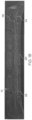
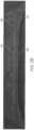
- FIG. 1A and FIG. 1B illustrate a first embodiment of a pneumatic tire, suitable for use as a truck tire.
- the tire 10 has a tread 12 with a non-skid depth D.
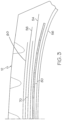
- the tire tread 12 may comprise a plurality of circumferentially continuous ribs, which may vary, but are shown for example as ribs 31, 32 and 33. Positioned between each rib is a circumferential groove 34, 35, 36, 37 which are preferably continuous.
- the tread may also comprise optional sipes (not shown).
- the tread pattern is not limited to same, and may comprise, for example, a plurality of blocks and grooves (not shown).
- the belt reinforcing package 50 includes a pair of extensible working belts, 54, 56. i.e., they are belts comprising parallel extensible cords with the angle of these cords defining the breaker angle.
- Belt 54 is located radially inwards of belt 56.
- Belt 54 has a width which is preferably equal or about equal (+/- 5 percent) to the tread arc width of the tire 10.
- belt 54 has a belt width equal or substantially equal (+/- 5 percent) to the tread arc width.
- the breaker angle of belt 54 is between 10 and 50 degrees, preferably with a right orientation.
- the belt structure 50 further includes a rubber layer 60 located between the zigzag belt reinforcing structure 58 and the tire carcass ply 18.
- the rubber layer 60 has an axial width which is the same or less than the axial width of the zigzag belt reinforcing structure 58.
- the rubber layer 60 preferably has a variable gauge (i.e., radial thickness), which ranges from 1.5 mm to 4 mm across the axial width of the rubber layer 60.
- the maximum gauge occurs in the center of the tread 12 and decreases to the lateral belt edge either continuously or stepwise.
- Cord or cable or wire is a relatively high elongation cord, cable or wire when it has, under a tensile force equal to 10% of the breaking force, a relative elongation greater than 0.2% or greater than 0.8% or greater than 1.5%, when taken from a cured tire.
- the belt structure 50 may further include an optional overlay belt 90, which is the radially outermost belt of the belt structure 50.
- an optional overlay belt 90 may be applies in any of the embodiments described above.
- the aspect ratio of the tire 10 described above may vary.
- the aspect ratio is preferably in the range of from 50 to 90.
- the tire preferably has a net to gross ratio in the range of 70 to 90, more preferably in the ratio of 74 to 86, more preferably 78 to 84.
Landscapes
- Engineering & Computer Science (AREA)
- Mechanical Engineering (AREA)
- Tires In General (AREA)
Claims (11)
- Reifen zur Verwendung auf Lastkraftwagen, wobei der Reifen eine Lauffläche (12), Flanken, eine Karkasse, ein Paar Wülste sowie eine Gürtelstruktur (50) besitzt, die in der radialen Richtung unterhalb der Lauffläche (12) angebracht ist, wobei die Gürtelstruktur (50) einen ersten Arbeitsgürtel (54) und einen zweiten Arbeitsgürtel (56) umfasst, wobei der erste Arbeitsgürtel (54) in der radialen Richtung unterhalb des zweiten Arbeitsgürtels (56) angebracht ist, wobei der Winkel, der durch den ersten und den zweiten Arbeitsgürtel (54, 56) gebildet wird, in einem Bereich von 10 Grad bis 50 Grad in Bezug auf die Umfangsrichtung liegt, wobei ein Zickzack-Gürtel (58) in der radialen Richtung unterhalb des ersten Arbeitsgürtels (54) oder zwischen dem ersten Arbeitsgürtel (54) und dem zweiten Arbeitsgürtel (56) angebracht ist, wobei eine Abstandschicht aus Kautschuk (60, 80) zwischen dem Zickzack-Gürtel (58) und der Karkasse des Reifens (10) oder zwischen dem ersten Arbeitsgürtel (54) und der Karkasse des Reifens (10) angebracht ist, und wobei der Zickzack-Gürtel (58) eine axiale Breite besitzt, die kleiner ist als die axiale Breite des ersten und des zweiten Arbeitsgürtels (54, 56).
- Reifen nach Anspruch 1, wobei die axiale Breite der Abstandschicht aus Kautschuk (60, 80) gleich der axialen Breite des Zickzack-Gürtels (58) ist oder in einem Bereich von 95 % bis 105 % der axialen Breite des Zickzack-Gürtels (58) liegt.
- Reifen nach Anspruch 1 oder 2, wobei die axiale Breite der Abstandsschicht aus Kautschuk (60, 80) kleiner ist als die axiale Breite des Zickzack-Gürtels (58).
- Reifen nach mindestens einem der vorhergehenden Ansprüche, wobei die Stärke oder die radiale Dicke der Abstandsschicht aus Kautschuk (60, 80) in der axialen Richtung variiert.
- Reifen nach Anspruch 4, wobei die Stärke oder die radiale Dicke der Abstandsschicht aus Kautschuk (60, 80) in einem Bereich von 1,5 mm bis 4 mm, vorzugsweise 1,5 mm bis 3 mm, über die axiale Breite der Abstandsschicht aus Kautschuk hinweg variiert.
- Reifen nach Anspruch 4 oder 5, wobei die Stärke oder die radiale Dicke der Abstandschicht aus Kautschuk (60, 80) einen Maximalwert in der Mitte der Lauffläche (12) oder in einem axialen Abstand in einem Bereich von 0 bis 30 mm in Bezug auf die Mitte der Lauffläche (12) hat, und/oder wobei die Stärke oder die radiale Dicke der Abstandsschicht aus Kautschuk (60, 80) in Richtung der seitlichen Kanten des Gürtels von dem Zentrum der Lauffläche (12) aus entweder kontinuierlich oder progressiv abnimmt.
- Reifen nach mindestens einem der vorhergehenden Ansprüche, wobei der erste und der zweite Arbeitsgürtel (54, 56) dehnbare Verstärkungskorde umfassen.
- Reifen nach mindestens einem der vorhergehenden Ansprüche, wobei der Zickzackgürtel (58) dehnbare Verstärkungskorde oder Verstärkungskorde umfasst, die eine relativ hohe Dehnung aufweisen.
- Reifen nach mindestens einem der vorhergehenden Ansprüche, wobei die Gürtelstruktur (50) nur drei Gürtel besitzt.
- Reifen nach mindestens einem der vorhergehenden Ansprüche, wobei die Gürtelstruktur (50) zusätzlich einen Gürtel in der Form eines Deckgürtels (90) als radial äußersten Gürtel der Gürtelstruktur (50) umfasst.
- Reifen nach mindestens einem der vorhergehenden Ansprüche, wobei der Reifen ein LKW-Reifen ist und für die Montage auf einer 22,5-Zoll-Felge vorgesehen ist.
Priority Applications (1)
| Application Number | Priority Date | Filing Date | Title |
|---|---|---|---|
| EP25181171.7A EP4603302A3 (de) | 2021-12-16 | 2022-12-13 | Lastwagenreifen |
Applications Claiming Priority (2)
| Application Number | Priority Date | Filing Date | Title |
|---|---|---|---|
| US202163265534P | 2021-12-16 | 2021-12-16 | |
| US18/059,012 US20230191842A1 (en) | 2021-12-16 | 2022-11-28 | Truck tire |
Related Child Applications (1)
| Application Number | Title | Priority Date | Filing Date |
|---|---|---|---|
| EP25181171.7A Division EP4603302A3 (de) | 2021-12-16 | 2022-12-13 | Lastwagenreifen |
Publications (2)
| Publication Number | Publication Date |
|---|---|
| EP4197814A1 EP4197814A1 (de) | 2023-06-21 |
| EP4197814B1 true EP4197814B1 (de) | 2025-07-02 |
Family
ID=86337510
Family Applications (2)
| Application Number | Title | Priority Date | Filing Date |
|---|---|---|---|
| EP22213039.5A Active EP4197814B1 (de) | 2021-12-16 | 2022-12-13 | Lastwagenreifen |
| EP25181171.7A Pending EP4603302A3 (de) | 2021-12-16 | 2022-12-13 | Lastwagenreifen |
Family Applications After (1)
| Application Number | Title | Priority Date | Filing Date |
|---|---|---|---|
| EP25181171.7A Pending EP4603302A3 (de) | 2021-12-16 | 2022-12-13 | Lastwagenreifen |
Country Status (2)
| Country | Link |
|---|---|
| US (1) | US20230191842A1 (de) |
| EP (2) | EP4197814B1 (de) |
Citations (1)
| Publication number | Priority date | Publication date | Assignee | Title |
|---|---|---|---|---|
| JP2002192908A (ja) * | 2000-12-26 | 2002-07-10 | Bridgestone Corp | 高速高荷重用ラジアルタイヤ |
Family Cites Families (7)
| Publication number | Priority date | Publication date | Assignee | Title |
|---|---|---|---|---|
| JP4015629B2 (ja) * | 2004-02-02 | 2007-11-28 | 住友ゴム工業株式会社 | 重荷重用タイヤ |
| US7575031B2 (en) * | 2005-11-22 | 2009-08-18 | Sumitomo Rubber Industries, Ltd. | Heavy duty radial tire with belt reinforcing rubber layer having axially inner and outer rubber portions |
| WO2011036893A1 (ja) * | 2009-09-24 | 2011-03-31 | 株式会社ブリヂストン | 空気入りタイヤ |
| KR20130077412A (ko) * | 2011-12-29 | 2013-07-09 | 금호타이어 주식회사 | 벨트와 카카스사이에 보강층을 갖는 중하중용 공기입 타이어 |
| FR3022840B1 (fr) * | 2014-06-26 | 2016-06-10 | Michelin & Cie | Pneumatique comportant une couche d'elements de renforcement circonferentiels |
| EP4140766B1 (de) * | 2021-08-24 | 2024-10-23 | Sumitomo Rubber Industries, Ltd. | Schwerlastluftreifen |
| EP4140767B1 (de) * | 2021-08-24 | 2024-10-30 | Sumitomo Rubber Industries, Ltd. | Schwerlastluftreifen |
-
2022
- 2022-11-28 US US18/059,012 patent/US20230191842A1/en not_active Abandoned
- 2022-12-13 EP EP22213039.5A patent/EP4197814B1/de active Active
- 2022-12-13 EP EP25181171.7A patent/EP4603302A3/de active Pending
Patent Citations (1)
| Publication number | Priority date | Publication date | Assignee | Title |
|---|---|---|---|---|
| JP2002192908A (ja) * | 2000-12-26 | 2002-07-10 | Bridgestone Corp | 高速高荷重用ラジアルタイヤ |
Also Published As
| Publication number | Publication date |
|---|---|
| EP4603302A3 (de) | 2025-11-12 |
| US20230191842A1 (en) | 2023-06-22 |
| EP4197814A1 (de) | 2023-06-21 |
| EP4603302A2 (de) | 2025-08-20 |
Similar Documents
| Publication | Publication Date | Title |
|---|---|---|
| EP2199104B1 (de) | Lastwagenreifen | |
| EP3838623B1 (de) | Lastwagenreifen | |
| CA2080852A1 (en) | Truck tire with split overlay | |
| EP2463124A2 (de) | Luftreifen | |
| EP4144539B1 (de) | Luftreifen zur verwendung auf einem lastwagen | |
| EP4011645B1 (de) | Lastwagenreifen | |
| EP4197815B1 (de) | Lastwagenreifen | |
| EP4197813B1 (de) | Lastwagenreifen | |
| EP4197814B1 (de) | Lastwagenreifen | |
| EP3838621B1 (de) | Luftreifen | |
| EP4011646B1 (de) | Lastwagenreifen | |
| EP2199108A1 (de) | Luftreifen | |
| US20220063336A1 (en) | Truck tire | |
| EP4011647B1 (de) | Lastwagenreifen | |
| US20220185035A1 (en) | Tire with improved bead structure | |
| EP3838622B1 (de) | Luftreifen | |
| EP3176005A1 (de) | Bidirektionale eingürtelkonstruktion für einen luftreifen |
Legal Events
| Date | Code | Title | Description |
|---|---|---|---|
| PUAI | Public reference made under article 153(3) epc to a published international application that has entered the european phase |
Free format text: ORIGINAL CODE: 0009012 |
|
| STAA | Information on the status of an ep patent application or granted ep patent |
Free format text: STATUS: THE APPLICATION HAS BEEN PUBLISHED |
|
| AK | Designated contracting states |
Kind code of ref document: A1 Designated state(s): AL AT BE BG CH CY CZ DE DK EE ES FI FR GB GR HR HU IE IS IT LI LT LU LV MC ME MK MT NL NO PL PT RO RS SE SI SK SM TR |
|
| STAA | Information on the status of an ep patent application or granted ep patent |
Free format text: STATUS: REQUEST FOR EXAMINATION WAS MADE |
|
| 17P | Request for examination filed |
Effective date: 20231221 |
|
| RBV | Designated contracting states (corrected) |
Designated state(s): AL AT BE BG CH CY CZ DE DK EE ES FI FR GB GR HR HU IE IS IT LI LT LU LV MC ME MK MT NL NO PL PT RO RS SE SI SK SM TR |
|
| STAA | Information on the status of an ep patent application or granted ep patent |
Free format text: STATUS: EXAMINATION IS IN PROGRESS |
|
| 17Q | First examination report despatched |
Effective date: 20240826 |
|
| GRAP | Despatch of communication of intention to grant a patent |
Free format text: ORIGINAL CODE: EPIDOSNIGR1 |
|
| STAA | Information on the status of an ep patent application or granted ep patent |
Free format text: STATUS: GRANT OF PATENT IS INTENDED |
|
| INTG | Intention to grant announced |
Effective date: 20250130 |
|
| GRAS | Grant fee paid |
Free format text: ORIGINAL CODE: EPIDOSNIGR3 |
|
| GRAA | (expected) grant |
Free format text: ORIGINAL CODE: 0009210 |
|
| STAA | Information on the status of an ep patent application or granted ep patent |
Free format text: STATUS: THE PATENT HAS BEEN GRANTED |
|
| AK | Designated contracting states |
Kind code of ref document: B1 Designated state(s): AL AT BE BG CH CY CZ DE DK EE ES FI FR GB GR HR HU IE IS IT LI LT LU LV MC ME MK MT NL NO PL PT RO RS SE SI SK SM TR |
|
| REG | Reference to a national code |
Ref country code: GB Ref legal event code: FG4D |
|
| REG | Reference to a national code |
Ref country code: CH Ref legal event code: EP |
|
| REG | Reference to a national code |
Ref country code: IE Ref legal event code: FG4D |
|
| REG | Reference to a national code |
Ref country code: DE Ref legal event code: R096 Ref document number: 602022016823 Country of ref document: DE |
|
| REG | Reference to a national code |
Ref country code: NL Ref legal event code: MP Effective date: 20250702 |
|
| PG25 | Lapsed in a contracting state [announced via postgrant information from national office to epo] |
Ref country code: PT Free format text: LAPSE BECAUSE OF FAILURE TO SUBMIT A TRANSLATION OF THE DESCRIPTION OR TO PAY THE FEE WITHIN THE PRESCRIBED TIME-LIMIT Effective date: 20251103 |
|
| PG25 | Lapsed in a contracting state [announced via postgrant information from national office to epo] |
Ref country code: NL Free format text: LAPSE BECAUSE OF FAILURE TO SUBMIT A TRANSLATION OF THE DESCRIPTION OR TO PAY THE FEE WITHIN THE PRESCRIBED TIME-LIMIT Effective date: 20250702 |
|
| REG | Reference to a national code |
Ref country code: AT Ref legal event code: MK05 Ref document number: 1808838 Country of ref document: AT Kind code of ref document: T Effective date: 20250702 |
|
| PG25 | Lapsed in a contracting state [announced via postgrant information from national office to epo] |
Ref country code: IS Free format text: LAPSE BECAUSE OF FAILURE TO SUBMIT A TRANSLATION OF THE DESCRIPTION OR TO PAY THE FEE WITHIN THE PRESCRIBED TIME-LIMIT Effective date: 20251102 |
|
| PGFP | Annual fee paid to national office [announced via postgrant information from national office to epo] |
Ref country code: DE Payment date: 20251126 Year of fee payment: 4 |
|
| PG25 | Lapsed in a contracting state [announced via postgrant information from national office to epo] |
Ref country code: NO Free format text: LAPSE BECAUSE OF FAILURE TO SUBMIT A TRANSLATION OF THE DESCRIPTION OR TO PAY THE FEE WITHIN THE PRESCRIBED TIME-LIMIT Effective date: 20251002 |
|
| REG | Reference to a national code |
Ref country code: LT Ref legal event code: MG9D |
|
| PG25 | Lapsed in a contracting state [announced via postgrant information from national office to epo] |
Ref country code: AT Free format text: LAPSE BECAUSE OF FAILURE TO SUBMIT A TRANSLATION OF THE DESCRIPTION OR TO PAY THE FEE WITHIN THE PRESCRIBED TIME-LIMIT Effective date: 20250702 |
|
| PG25 | Lapsed in a contracting state [announced via postgrant information from national office to epo] |
Ref country code: FI Free format text: LAPSE BECAUSE OF FAILURE TO SUBMIT A TRANSLATION OF THE DESCRIPTION OR TO PAY THE FEE WITHIN THE PRESCRIBED TIME-LIMIT Effective date: 20250702 |
|
| PG25 | Lapsed in a contracting state [announced via postgrant information from national office to epo] |
Ref country code: HR Free format text: LAPSE BECAUSE OF FAILURE TO SUBMIT A TRANSLATION OF THE DESCRIPTION OR TO PAY THE FEE WITHIN THE PRESCRIBED TIME-LIMIT Effective date: 20250702 |
|
| PGFP | Annual fee paid to national office [announced via postgrant information from national office to epo] |
Ref country code: FR Payment date: 20251120 Year of fee payment: 4 |
|
| PG25 | Lapsed in a contracting state [announced via postgrant information from national office to epo] |
Ref country code: GR Free format text: LAPSE BECAUSE OF FAILURE TO SUBMIT A TRANSLATION OF THE DESCRIPTION OR TO PAY THE FEE WITHIN THE PRESCRIBED TIME-LIMIT Effective date: 20251003 |
|
| PGFP | Annual fee paid to national office [announced via postgrant information from national office to epo] |
Ref country code: TR Payment date: 20251202 Year of fee payment: 4 |
|
| PG25 | Lapsed in a contracting state [announced via postgrant information from national office to epo] |
Ref country code: SE Free format text: LAPSE BECAUSE OF FAILURE TO SUBMIT A TRANSLATION OF THE DESCRIPTION OR TO PAY THE FEE WITHIN THE PRESCRIBED TIME-LIMIT Effective date: 20250702 Ref country code: CZ Free format text: LAPSE BECAUSE OF FAILURE TO SUBMIT A TRANSLATION OF THE DESCRIPTION OR TO PAY THE FEE WITHIN THE PRESCRIBED TIME-LIMIT Effective date: 20250702 |
|
| PG25 | Lapsed in a contracting state [announced via postgrant information from national office to epo] |
Ref country code: LV Free format text: LAPSE BECAUSE OF FAILURE TO SUBMIT A TRANSLATION OF THE DESCRIPTION OR TO PAY THE FEE WITHIN THE PRESCRIBED TIME-LIMIT Effective date: 20250702 |
|
| PG25 | Lapsed in a contracting state [announced via postgrant information from national office to epo] |
Ref country code: BG Free format text: LAPSE BECAUSE OF FAILURE TO SUBMIT A TRANSLATION OF THE DESCRIPTION OR TO PAY THE FEE WITHIN THE PRESCRIBED TIME-LIMIT Effective date: 20250702 Ref country code: PL Free format text: LAPSE BECAUSE OF FAILURE TO SUBMIT A TRANSLATION OF THE DESCRIPTION OR TO PAY THE FEE WITHIN THE PRESCRIBED TIME-LIMIT Effective date: 20250702 |
|
| PG25 | Lapsed in a contracting state [announced via postgrant information from national office to epo] |
Ref country code: RS Free format text: LAPSE BECAUSE OF FAILURE TO SUBMIT A TRANSLATION OF THE DESCRIPTION OR TO PAY THE FEE WITHIN THE PRESCRIBED TIME-LIMIT Effective date: 20251002 |
|
| PG25 | Lapsed in a contracting state [announced via postgrant information from national office to epo] |
Ref country code: ES Free format text: LAPSE BECAUSE OF FAILURE TO SUBMIT A TRANSLATION OF THE DESCRIPTION OR TO PAY THE FEE WITHIN THE PRESCRIBED TIME-LIMIT Effective date: 20250702 |