EP4144539B1 - Luftreifen zur verwendung auf einem lastwagen - Google Patents
Luftreifen zur verwendung auf einem lastwagen Download PDFInfo
- Publication number
- EP4144539B1 EP4144539B1 EP22193017.5A EP22193017A EP4144539B1 EP 4144539 B1 EP4144539 B1 EP 4144539B1 EP 22193017 A EP22193017 A EP 22193017A EP 4144539 B1 EP4144539 B1 EP 4144539B1
- Authority
- EP
- European Patent Office
- Prior art keywords
- belt
- tire
- working
- relatively low
- percent
- Prior art date
- Legal status (The legal status is an assumption and is not a legal conclusion. Google has not performed a legal analysis and makes no representation as to the accuracy of the status listed.)
- Active
Links
Images
Classifications
-
- B—PERFORMING OPERATIONS; TRANSPORTING
- B60—VEHICLES IN GENERAL
- B60C—VEHICLE TYRES; TYRE INFLATION; TYRE CHANGING; CONNECTING VALVES TO INFLATABLE ELASTIC BODIES IN GENERAL; DEVICES OR ARRANGEMENTS RELATED TO TYRES
- B60C9/00—Reinforcements or ply arrangement of pneumatic tyres
- B60C9/18—Structure or arrangement of belts or breakers, crown-reinforcing or cushioning layers
- B60C9/26—Folded plies
-
- B—PERFORMING OPERATIONS; TRANSPORTING
- B60—VEHICLES IN GENERAL
- B60C—VEHICLE TYRES; TYRE INFLATION; TYRE CHANGING; CONNECTING VALVES TO INFLATABLE ELASTIC BODIES IN GENERAL; DEVICES OR ARRANGEMENTS RELATED TO TYRES
- B60C9/00—Reinforcements or ply arrangement of pneumatic tyres
- B60C9/18—Structure or arrangement of belts or breakers, crown-reinforcing or cushioning layers
- B60C9/20—Structure or arrangement of belts or breakers, crown-reinforcing or cushioning layers built-up from rubberised plies each having all cords arranged substantially parallel
- B60C9/2003—Structure or arrangement of belts or breakers, crown-reinforcing or cushioning layers built-up from rubberised plies each having all cords arranged substantially parallel characterised by the materials of the belt cords
- B60C9/2006—Structure or arrangement of belts or breakers, crown-reinforcing or cushioning layers built-up from rubberised plies each having all cords arranged substantially parallel characterised by the materials of the belt cords consisting of steel cord plies only
-
- B—PERFORMING OPERATIONS; TRANSPORTING
- B60—VEHICLES IN GENERAL
- B60C—VEHICLE TYRES; TYRE INFLATION; TYRE CHANGING; CONNECTING VALVES TO INFLATABLE ELASTIC BODIES IN GENERAL; DEVICES OR ARRANGEMENTS RELATED TO TYRES
- B60C9/00—Reinforcements or ply arrangement of pneumatic tyres
- B60C9/18—Structure or arrangement of belts or breakers, crown-reinforcing or cushioning layers
- B60C2009/1871—Structure or arrangement of belts or breakers, crown-reinforcing or cushioning layers with flat cushions or shear layers between belt layers
-
- B—PERFORMING OPERATIONS; TRANSPORTING
- B60—VEHICLES IN GENERAL
- B60C—VEHICLE TYRES; TYRE INFLATION; TYRE CHANGING; CONNECTING VALVES TO INFLATABLE ELASTIC BODIES IN GENERAL; DEVICES OR ARRANGEMENTS RELATED TO TYRES
- B60C9/00—Reinforcements or ply arrangement of pneumatic tyres
- B60C9/18—Structure or arrangement of belts or breakers, crown-reinforcing or cushioning layers
- B60C9/20—Structure or arrangement of belts or breakers, crown-reinforcing or cushioning layers built-up from rubberised plies each having all cords arranged substantially parallel
- B60C2009/2012—Structure or arrangement of belts or breakers, crown-reinforcing or cushioning layers built-up from rubberised plies each having all cords arranged substantially parallel with particular configuration of the belt cords in the respective belt layers
- B60C2009/2016—Structure or arrangement of belts or breakers, crown-reinforcing or cushioning layers built-up from rubberised plies each having all cords arranged substantially parallel with particular configuration of the belt cords in the respective belt layers comprising cords at an angle of 10 to 30 degrees to the circumferential direction
-
- B—PERFORMING OPERATIONS; TRANSPORTING
- B60—VEHICLES IN GENERAL
- B60C—VEHICLE TYRES; TYRE INFLATION; TYRE CHANGING; CONNECTING VALVES TO INFLATABLE ELASTIC BODIES IN GENERAL; DEVICES OR ARRANGEMENTS RELATED TO TYRES
- B60C9/00—Reinforcements or ply arrangement of pneumatic tyres
- B60C9/18—Structure or arrangement of belts or breakers, crown-reinforcing or cushioning layers
- B60C9/20—Structure or arrangement of belts or breakers, crown-reinforcing or cushioning layers built-up from rubberised plies each having all cords arranged substantially parallel
- B60C2009/2012—Structure or arrangement of belts or breakers, crown-reinforcing or cushioning layers built-up from rubberised plies each having all cords arranged substantially parallel with particular configuration of the belt cords in the respective belt layers
- B60C2009/2019—Structure or arrangement of belts or breakers, crown-reinforcing or cushioning layers built-up from rubberised plies each having all cords arranged substantially parallel with particular configuration of the belt cords in the respective belt layers comprising cords at an angle of 30 to 60 degrees to the circumferential direction
-
- B—PERFORMING OPERATIONS; TRANSPORTING
- B60—VEHICLES IN GENERAL
- B60C—VEHICLE TYRES; TYRE INFLATION; TYRE CHANGING; CONNECTING VALVES TO INFLATABLE ELASTIC BODIES IN GENERAL; DEVICES OR ARRANGEMENTS RELATED TO TYRES
- B60C9/00—Reinforcements or ply arrangement of pneumatic tyres
- B60C9/18—Structure or arrangement of belts or breakers, crown-reinforcing or cushioning layers
- B60C9/20—Structure or arrangement of belts or breakers, crown-reinforcing or cushioning layers built-up from rubberised plies each having all cords arranged substantially parallel
- B60C2009/2012—Structure or arrangement of belts or breakers, crown-reinforcing or cushioning layers built-up from rubberised plies each having all cords arranged substantially parallel with particular configuration of the belt cords in the respective belt layers
- B60C2009/2022—Structure or arrangement of belts or breakers, crown-reinforcing or cushioning layers built-up from rubberised plies each having all cords arranged substantially parallel with particular configuration of the belt cords in the respective belt layers comprising cords at an angle of 60 to 90 degrees to the circumferential direction
-
- B—PERFORMING OPERATIONS; TRANSPORTING
- B60—VEHICLES IN GENERAL
- B60C—VEHICLE TYRES; TYRE INFLATION; TYRE CHANGING; CONNECTING VALVES TO INFLATABLE ELASTIC BODIES IN GENERAL; DEVICES OR ARRANGEMENTS RELATED TO TYRES
- B60C9/00—Reinforcements or ply arrangement of pneumatic tyres
- B60C9/18—Structure or arrangement of belts or breakers, crown-reinforcing or cushioning layers
- B60C9/20—Structure or arrangement of belts or breakers, crown-reinforcing or cushioning layers built-up from rubberised plies each having all cords arranged substantially parallel
- B60C2009/2035—Structure or arrangement of belts or breakers, crown-reinforcing or cushioning layers built-up from rubberised plies each having all cords arranged substantially parallel built-up by narrow strips
-
- B—PERFORMING OPERATIONS; TRANSPORTING
- B60—VEHICLES IN GENERAL
- B60C—VEHICLE TYRES; TYRE INFLATION; TYRE CHANGING; CONNECTING VALVES TO INFLATABLE ELASTIC BODIES IN GENERAL; DEVICES OR ARRANGEMENTS RELATED TO TYRES
- B60C9/00—Reinforcements or ply arrangement of pneumatic tyres
- B60C9/18—Structure or arrangement of belts or breakers, crown-reinforcing or cushioning layers
- B60C9/20—Structure or arrangement of belts or breakers, crown-reinforcing or cushioning layers built-up from rubberised plies each having all cords arranged substantially parallel
- B60C2009/2074—Physical properties or dimension of the belt cord
- B60C2009/2093—Elongation of the reinforcements at break point
-
- B—PERFORMING OPERATIONS; TRANSPORTING
- B60—VEHICLES IN GENERAL
- B60C—VEHICLE TYRES; TYRE INFLATION; TYRE CHANGING; CONNECTING VALVES TO INFLATABLE ELASTIC BODIES IN GENERAL; DEVICES OR ARRANGEMENTS RELATED TO TYRES
- B60C9/00—Reinforcements or ply arrangement of pneumatic tyres
- B60C9/18—Structure or arrangement of belts or breakers, crown-reinforcing or cushioning layers
- B60C9/20—Structure or arrangement of belts or breakers, crown-reinforcing or cushioning layers built-up from rubberised plies each having all cords arranged substantially parallel
- B60C9/22—Structure or arrangement of belts or breakers, crown-reinforcing or cushioning layers built-up from rubberised plies each having all cords arranged substantially parallel the plies being arranged with all cords disposed along the circumference of the tyre
- B60C2009/2219—Structure or arrangement of belts or breakers, crown-reinforcing or cushioning layers built-up from rubberised plies each having all cords arranged substantially parallel the plies being arranged with all cords disposed along the circumference of the tyre with a partial zero degree ply at the belt edges - edge band
-
- B—PERFORMING OPERATIONS; TRANSPORTING
- B60—VEHICLES IN GENERAL
- B60C—VEHICLE TYRES; TYRE INFLATION; TYRE CHANGING; CONNECTING VALVES TO INFLATABLE ELASTIC BODIES IN GENERAL; DEVICES OR ARRANGEMENTS RELATED TO TYRES
- B60C2200/00—Tyres specially adapted for particular applications
- B60C2200/06—Tyres specially adapted for particular applications for heavy duty vehicles
Definitions
- the invention relates in general to pneumatic tires, and more particularly to pneumatic tires for vehicles such as trucks.
- the commercial truck market is moving towards an increase in overall vehicle weight, which is due in part to the increase in weight of the motor and equipment.
- the increase in overall vehicle weight requires a tire capable of handling the additional loading.
- a tire with improved crown durability and increased load carrying capacity is desired.
- JP 2004 322783 A describes a further truck tire having a folded ply.
- Bead or “Bead Core” mean generally that part of the tire comprising an annular tensile member, the radially inner beads are associated with holding the tire to the rim being wrapped by ply cords and shaped, with or without other reinforcement elements such as flippers, chippers, apexes or fillers, toe guards and chafers.
- Belt Structure (or “Reinforcing Belts” or “Belt Package”) means at least two annular layers or plies of parallel cords, woven or unwoven, underlying the tread, unanchored to the bead.
- Carcass means a laminate of tire ply material and other tire components cut to length suitable for splicing, or already spliced, into a cylindrical or toroidal shape. Additional components may be added to the carcass prior to its being vulcanized to create the molded tire.
- “Circumferential” means lines or directions perpendicular to the axial direction.
- Core means one of the reinforcement strands, including fibers, which are used to reinforce the plies.
- Extensible means a cable, cord, wire, or reinforcement having an elongation at 10% of the breaking load greater than 0.2%, when measured from a cord extracted from a cured tire.
- the tensile measurements such as the load at break (maximum load in N), strength at break (in MPa) and elongation at break (total elongation in %) are performed in tension in accordance with ISO 6892-1B (2019) at a pre-load no more than 10 MPa tested on a cable or wire when taken from a cured tire.
- Inner Liner means the layer or layers of elastomer or other material that form the inside surface of a tubeless tire and that contain the inflating fluid within the tire.
- Ply means a cord-reinforced layer of elastomer-coated, radially deployed or otherwise parallel cords.
- Ring and radially mean directions radially toward or away from the axis of rotation of the tire.
- Ring Ply Structure means the one or more carcass plies or which at least one ply has reinforcing cords oriented at an angle of between 65° and 90° with respect to the equatorial plane of the tire.
- the invention relates to a tire in accordance with claim 1.
- a pneumatic tire comprising a tread and a belt structure located radially inward of the tread, the belt structure including a pair of working belts, wherein the working belts are reinforced plies each comprising parallel reinforcement elements, wherein the angle of the reinforcement elements in the respective working belt ranges from 12 degrees to 35 degrees with respect to the circumferential direction, wherein the belt structure further includes a relatively low angle belt preferably positioned radially between the working belts, the relatively low angle belt comprising parallel reinforcement elements angled at less than 5 degrees, preferably less than 2 degrees, with respect to the circumferential direction, wherein the relatively low angle belt has folded belt edges forming a first and second narrow belt at the lateral ends of the relatively low angle belt, and wherein the first and second narrow belt are each positioned radially inward of and each at least partially extend axially under a respective axially outermost groove on each respective lateral side of the tread.
- the reinforcement elements in the working belts and/or in the relatively low angle belt have an elongation at 10% of the breaking load greater than 0.2%, alternatively greater than 0.4%, when measured at the reinforcement elements extracted from a cured tire.
- the reinforcement elements in the working belts and/or in the relatively low angle belt are wires comprising steel or are hybrid cords.
- the axial width of each of the narrow belts is in the range of from 2.54 cm to 7.62 cm and/or the axial width of each of the narrow belts is less than 1/3, preferably in a range of from 5 percent to 20 percent, of the tread arc width.
- the axial width of each of the narrow belts is in the range of one to two times, preferably 1.2 to 1.8 times, the axial width of the respective groove located radially outward of the respective narrow belt.
- the reinforcement elements in the working belts and/or in the relatively low angle belt have an elongation at 10% of the breaking load greater 0.8% or greater than 1.5%, when measured at the reinforcement elements extracted from a cured tire.
- the radially inner working belt has an axial width equal or about equal to the tread arc width or in a range of from 95 percent to 105 percent of the tread arc width.
- the radially outer working belt has an axial width less, preferably at least 5 percent less, than the radially inner working belt; and/or and wherein the radially inner working belt is the axially widest belt of the belt structure.
- the relatively low angle belt has an axial width in the range of from 70 to 80 percent of the tread arc width.
- the tire further includes a top belt as the radially outermost belt of the belt structure.
- the tire further includes a transition belt located radially inwards of the working belts.
- the transition belt comprises parallel reinforcement elements making an angle in a range of from 45 to 70 degrees, preferably from 45 to 70 degrees right, with the circumferential direction; and/or wherein the transition belt has an axial width in a range of from 60 to 80 percent of the tread arc width.
- the aspect ratio of the tire is less than or equal to 0.6.
- the folded belts each comprise parallel reinforcement elements angled at the same angle as the adjacent second working belt.
- the tire further comprises a rubber spacer layer located between the folded belt edges that preferably extends over at least 80 percent, more preferably at least 95 percent, of the axial distance between the axially innermost ends of the folded belt edges.
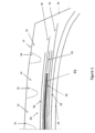
- FIG. 1 illustrates a first embodiment of a pneumatic tire, suitable for use as a truck tire.
- the tire 10 has a tread 12 with a non-skid depth.
- the tire tread 12 comprises a plurality of circumferentially continuous ribs, which may vary, but are shown for example as ribs 31, 32 and 33. Positioned between each rib are circumferential grooves 34, 35, 36, which are preferably continuous.
- the tread may also comprise optional sipes (not shown).
- the tread pattern is not limited to same, and may comprise, for example, a plurality of blocks and grooves (not shown).
- the tire 10 further comprises a casing which includes two opposed sidewalls 16 which extend down from the tread 12 to the bead area (not shown).
- the casing of the tire preferably includes an inner liner 18 which is typically formed of halobutyl rubber which forms an air impervious barrier.
- the tire casing preferably further includes one or more radial plies 19 extending from the tread, down the sidewall to the tire bead and wrapped about or otherwise secured to each annular bead.
- the tire 10 further includes a belt package 50 which is located between the tread and the one or more casing plies 19.
- the belt package comprises layers of reinforcement.
- the ply 19 and the belt reinforcing structure 50 are made from cord reinforced elastomeric material, wherein the cords are preferably steel wire or polyamide filaments and the elastomer preferably being rubber.
- the belt reinforcing structure 50 includes a radially innermost first working belt 54.
- the first working belt 54 is located radially inwards of the second working belt 56 and is preferably the widest belt layer of the belt reinforcing structure 50.
- the first working belt 54 has a width which is preferably equal or, about equal, i.e., ⁇ 5%, to the tread arc width.
- the breaker angle of belt 54 is between 10 and 50 degrees, preferably with a right orientation, more preferably in the range of 19 to 25 degrees.
- Belt 54 is preferably made of extensible wire which has a % elongation at 10% of breaking load of greater than 0.2%.
- the wire is preferably a hybrid cord or a steel wire.
- the second working belt 56 is the second member of the working belt pair.
- the second working belt 56 has a width less than the width of the first working belt 54 and is preferably radially outward of the first working belt 54.
- the second working belt 56 has a width less than the width of belt 54 by a step off, which preferably ranges from 10 to 20 mm.
- Belt 56 has a breaker angle between 12 and 35 degrees, preferably with a left orientation, more preferably in the range of 19 to 25 degrees.
- Belt 56 is preferably made of extensible wire and is the same as the wire of the first working belt 54. More preferably, the wire has the same construction with the same but opposite angular orientation as the wire of belt 54.
- the belt structure 50 further comprises a relatively low angle belt 58 which is preferably located between the working pair belts, 54, 56.
- the relatively low angle belt 58 has reinforcements that are oriented circumferentially at 5 degrees or less, preferably 2 degrees or less, more preferably 0 degrees.
- the relatively low angle belt 58 has a belt width which is preferably less than the belt width of the working belts 54, 56.
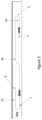
- the relatively low angle belt 58 is preferably formed from spirally winding a rubberized strip of one or more cords in a pattern as shown in FIG. 2 .
- the strip has 3, 4 or 5 steel cords, and has a width in the range of from 5 to 10 mm, more preferably from 4 to 6 mm.
- a rubberized strip of reinforcement cords is wound on a drum, starting on the right-hand side 5 of the drum, at a location axially inward from the right edge of the drum. The strip is applied at the starting location 5 and then helically wound in an axially outward direction towards the axially outer edge 6 of the drum. The strip is then wound in a change of direction towards the left-hand side 7 of the drum.
- the layup results in a wide relatively low angle belt 58 that has folded belt edges 62, wherein the relatively low angle belt has folded belt edges forming a first and second narrow belt 62 at the lateral ends of the relatively low angle belt.
- the folded belt edges 62 have a relatively narrow axial width and are located on each lateral edge of the belt and are positioned radially inward of the axially outermost shoulder groove 36.
- the folded belt edge belt 62 preferably is the narrowest belt.
- the axial width of the folded belt 62 is preferably in the range of one to four times the axial width of the groove 36.
- the folded belt 62 has the same angle and orientation as the adjacent belt 56.
- a rubber spacer 64 is preferably located between the folded belt edges 62, and functions to fill the void between the folded belt edges 62.
- the relatively low angle belt 58 has a width sized to avoid compression in the shoulder area.
- the belt width of the relatively low angle belt 58 is preferably in the range of 70% to 80% of the tread arc width, and even more preferably in the range of 73-77%.
- the relatively low angle belt 58 is preferably wide enough to decrease the strain cycles in the breaker wedge and is just stopped before the shoulder area to avoid zero degree wire compression and a too round footprint.
- the relatively low angle belt 58 is preferably formed using high tensile steel and preferably has a % elongation at 10% of breaking load of 0.18 or more, for measurements taken from a cured tire. For measurements taken from bare cords, the % elongation at 10% of breaking load is 0.2 or more.
- the relatively low angle belt 58 may be formed using non-metal reinforcements such as aramid, carbon fiber, polyketone or POK.
- the belt structure 50 may further comprise an optional top belt 60.
- This top belt 60 preferably has an axial width less than the working belts 54, 56.
- the aspect ratio of the tire described above may vary.
- the aspect ratio is preferably in the range of from 0.4 to 0.6 such as 0.45 or 0.55.
- the tire preferably has a net to gross ratio in the range of 70 to 90, more preferably in the range of 74 to 86, more preferably a 78 to 84.
Landscapes
- Engineering & Computer Science (AREA)
- Mechanical Engineering (AREA)
- Tires In General (AREA)
Claims (14)
- Luftreifen, der eine Lauffläche (12) und eine Gürtelstruktur (50) umfasst, die in der radialen Richtung innerhalb der Lauffläche (12) aufgebracht ist; wobei die Gürtelstruktur (50) ein Paar von Arbeitsgürteln (54, 56) enthält; wobei die Arbeitsgürtel (54, 56) verstärkte Lagen darstellen, die jeweils parallele Verstärkungselemente umfassen; wobei der Winkel, der durch die Verstärkungselemente in dem jeweiligen Arbeitsgürtel (54, 56) gebildet wird, in dem Bereich von 12 Grad bis 35 Grad in Bezug auf die Umfangsrichtung liegt; wobei die Gürtelstruktur (50) ferner einen Gürtel (58) umfasst, der einen relativ kleinen Winkel bildet, der in der radialen Richtung vorzugsweise zwischen den Arbeitsgürteln (54, 56) positioniert ist; wobei der Gürtel (58), der einen relativ kleinen Winkel bildet, parallele Verstärkungselemente umfasst, die einen Winkel von mindestens weniger als 5 Grad, vorzugsweise weniger als 2 Grad, in Bezug auf die Umfangsrichtung bilden; wobei der Gürtel (58), der einen relativ kleinen Winkel bildet, umgeschlagene Gürtelkanten (62) aufweist, die einen ersten und einen zweiten schmalen Gürtel an den seitlichen Enden des Gürtels (58) bilden, der einen relativ kleinen Winkel bildet; und wobei der erste und der zweite schmale Gürtel jeweils in der radialen Richtung innerhalb einer jeweiligen in der axialen Richtung äußersten Nut positioniert sind und sich jeweils in der axialen Richtung zumindest teilweise unterhalb der oben genannten Nut auf jeder jeweiligen seitlichen Seite der Lauffläche (12) erstrecken, dadurch gekennzeichnet, dass die Gürtelstruktur (50) ferner eine als Abstandshalter dienende Gummischicht (64) umfasst, die zwischen den umgeschlagenen Gürtelkanten (62) aufgebracht ist.
- Luftreifen nach Anspruch 1, wobei die Verstärkungselemente in den Arbeitsgürteln (54, 56) und/oder in dem Gürtel (58), der einen relativ kleinen Winkel bildet, eine Dehnung bei 10 % Bruchlast haben, die größer als 0,2 %, alternativ größer als 0,4 %, ist, wenn sie an den Verstärkungselementen gemessen wird, die aus einem Reifen in vulkanisiertem Zustand entnommen wurden.
- Luftreifen nach Anspruch 1, wobei die Verstärkungselemente in den Arbeitsgürteln (54, 56) und/oder in dem Gürtel (58), der einen relativ kleinen Winkel bildet, Metalldrähte sind, die Stahl umfassen oder Hybridcorde darstellen.
- Luftreifen nach einem der vorhergehenden Ansprüche, wobei die axiale Breite jedes der schmalen Gürtel in dem Bereich von 2,54 cm bis 7,62 cm liegt und/oder wobei die axiale Breite jedes der schmalen Gürtel (36) weniger als 1/3, vorzugsweise in einem Bereich von 5 Prozent bis 20 Prozent, der Konturbreite der Lauffläche ausmacht.
- Luftreifen nach einem der vorhergehenden Ansprüche, wobei die axiale Breite jedes der schmalen Gürtel in dem Bereich des Ein- bis Zweifachen, vorzugsweise des 1,2- bis 1,8-fachen der axialen Breite der jeweiligen Nut (36) liegt, die in der radialen Richtung außerhalb des jeweiligen schmalen Gürtels (63) aufgebracht ist.
- Luftreifen nach einem der vorhergehenden Ansprüche, wobei die Verstärkungselemente in den Arbeitsgürteln (54, 56) und/oder in dem Gürtel (58), der einen relativ kleinen Winkel bildet, eine Dehnung bei 10 % Bruchlast haben, die größer als 0,8 % oder größer als 1,5 % ist, wenn sie an den Verstärkungselementen gemessen wird, die aus einem Reifen in vulkanisiertem Zustand entnommen wurden.
- Luftreifen nach einem der vorhergehenden Ansprüche, wobei der in der radialen Richtung innere Arbeitsgürtel (54) eine axiale Breite hat, die gleich oder ungefähr gleich der Konturbreite der Lauffläche ist oder in einem Bereich liegt, der 95 Prozent bis 105 Prozent der Konturbreite der Lauffläche ausmacht.
- Luftreifen nach einem der vorhergehenden Ansprüche, wobei der in der radialen Richtung äußere Arbeitsgürtel (56) eine axiale Breite aufweist, die kleiner, vorzugsweise um mindestens 5 Prozent kleiner als der in der radialen Richtung innere Arbeitsgürtel (54) ist; und/oder der in der radialen Richtung innere Arbeitsgürtel (54) der in der axialen Richtung breiteste Gürtel der Gürtelstruktur (50) ist.
- Luftreifen nach einem der vorhergehenden Ansprüche, wobei der Gürtel (58), der einen relativ kleinen Winkel bildet, eine axiale Breite hat, die in einem Bereich liegt, der 70 Prozent bis 80 Prozent der Konturbreite der Lauffläche ausmacht.
- Luftreifen nach einem der vorhergehenden Ansprüche, der außerdem einen oberen Gürtel (60) als den in der radialen Richtung äußersten Gürtel der Gürtelstruktur (50) enthält.
- Luftreifen nach einem der vorhergehenden Ansprüche, der außerdem einen Übergangsgürtel enthält, der in der radialen Richtung am weitesten innen von den Arbeitsgürteln (54, 56) liegt.
- Luftreifen nach Anspruch 11, wobei der Übergangsgürtel parallele Verstärkungselemente umfasst, die mit der Umfangsrichtung einen Winkel bilden, der in einem Bereich von 45 bis 70 Grad, vorzugsweise von 45 bis 70 Grad nach rechts, liegt; und/oder wobei der Übergangsgürtel eine axiale Breite hat, die in einem Bereich liegt, der 60 bis 80 Prozent der Konturbreite der Lauffläche ausmacht.
- Luftreifen nach einem der vorhergehenden Ansprüche, wobei das Aspektverhältnis des Reifens kleiner als oder gleich 0,6 ist.
- Luftreifen nach einem der vorhergehenden Ansprüche, wobei sich die als Abstandshalter (64) dienende Gummischicht über eine Strecke erstreckt, die mindestens 80%, bevorzugter mindestens 95%, des axialen Abstands zwischen den in der axialen Richtung innersten Enden der umgeschlagenen Gürtelkanten (62) beträgt.
Applications Claiming Priority (2)
| Application Number | Priority Date | Filing Date | Title |
|---|---|---|---|
| US202163260818P | 2021-09-01 | 2021-09-01 | |
| US17/809,598 US20230064757A1 (en) | 2021-09-01 | 2022-06-29 | Truck tire |
Publications (2)
| Publication Number | Publication Date |
|---|---|
| EP4144539A1 EP4144539A1 (de) | 2023-03-08 |
| EP4144539B1 true EP4144539B1 (de) | 2025-01-22 |
Family
ID=83151381
Family Applications (1)
| Application Number | Title | Priority Date | Filing Date |
|---|---|---|---|
| EP22193017.5A Active EP4144539B1 (de) | 2021-09-01 | 2022-08-30 | Luftreifen zur verwendung auf einem lastwagen |
Country Status (2)
| Country | Link |
|---|---|
| US (1) | US20230064757A1 (de) |
| EP (1) | EP4144539B1 (de) |
Families Citing this family (2)
| Publication number | Priority date | Publication date | Assignee | Title |
|---|---|---|---|---|
| US20230191845A1 (en) * | 2021-12-16 | 2023-06-22 | The Goodyear Tire & Rubber Company | Truck tire |
| US20240424834A1 (en) * | 2023-06-20 | 2024-12-26 | The Goodyear Tire & Rubber Company | Tire comprising a low angle belt |
Family Cites Families (5)
| Publication number | Priority date | Publication date | Assignee | Title |
|---|---|---|---|---|
| DE2115914A1 (de) * | 1971-04-01 | 1972-10-05 | Umroyal AG, 5100 Aachen | Fahrzeugluftreifen, insbesondere fur hohe und höchste Fahrzeuggeschwindigkei ten |
| US4135566A (en) * | 1971-04-01 | 1979-01-23 | Uniroyal Gmbh | Belted pneumatic tires |
| JPH03128702A (ja) * | 1989-07-24 | 1991-05-31 | Sumitomo Rubber Ind Ltd | 重荷重用タイヤ |
| JP4305632B2 (ja) * | 2003-04-23 | 2009-07-29 | 横浜ゴム株式会社 | 重荷重用空気入りラジアルタイヤ |
| RU2427475C2 (ru) * | 2006-09-22 | 2011-08-27 | Сумитомо Раббер Индастриз, Лтд. | Большегрузная радиальная шина |
-
2022
- 2022-06-29 US US17/809,598 patent/US20230064757A1/en not_active Abandoned
- 2022-08-30 EP EP22193017.5A patent/EP4144539B1/de active Active
Also Published As
| Publication number | Publication date |
|---|---|
| US20230064757A1 (en) | 2023-03-02 |
| EP4144539A1 (de) | 2023-03-08 |
Similar Documents
| Publication | Publication Date | Title |
|---|---|---|
| EP2199104B1 (de) | Lastwagenreifen | |
| EP3838623B1 (de) | Lastwagenreifen | |
| US5435369A (en) | Truck tire with split overlay | |
| EP3838619B1 (de) | Luftreifen | |
| EP4144539B1 (de) | Luftreifen zur verwendung auf einem lastwagen | |
| EP4011645B1 (de) | Lastwagenreifen | |
| EP4197815B1 (de) | Lastwagenreifen | |
| EP4197813B1 (de) | Lastwagenreifen | |
| EP3838621B1 (de) | Luftreifen | |
| US20220063336A1 (en) | Truck tire | |
| US20220185020A1 (en) | Truck tire | |
| US20220185035A1 (en) | Tire with improved bead structure | |
| US20230191842A1 (en) | Truck tire | |
| US20080163969A1 (en) | Pneumatic tire with buttressed sidewall | |
| US20220185018A1 (en) | Truck tire | |
| US20050133138A1 (en) | Pneumatic tire with improved crown durability | |
| EP3838622B1 (de) | Luftreifen |
Legal Events
| Date | Code | Title | Description |
|---|---|---|---|
| PUAI | Public reference made under article 153(3) epc to a published international application that has entered the european phase |
Free format text: ORIGINAL CODE: 0009012 |
|
| STAA | Information on the status of an ep patent application or granted ep patent |
Free format text: STATUS: THE APPLICATION HAS BEEN PUBLISHED |
|
| AK | Designated contracting states |
Kind code of ref document: A1 Designated state(s): AL AT BE BG CH CY CZ DE DK EE ES FI FR GB GR HR HU IE IS IT LI LT LU LV MC MK MT NL NO PL PT RO RS SE SI SK SM TR |
|
| STAA | Information on the status of an ep patent application or granted ep patent |
Free format text: STATUS: REQUEST FOR EXAMINATION WAS MADE |
|
| 17P | Request for examination filed |
Effective date: 20230908 |
|
| RBV | Designated contracting states (corrected) |
Designated state(s): AL AT BE BG CH CY CZ DE DK EE ES FI FR GB GR HR HU IE IS IT LI LT LU LV MC MK MT NL NO PL PT RO RS SE SI SK SM TR |
|
| GRAP | Despatch of communication of intention to grant a patent |
Free format text: ORIGINAL CODE: EPIDOSNIGR1 |
|
| STAA | Information on the status of an ep patent application or granted ep patent |
Free format text: STATUS: GRANT OF PATENT IS INTENDED |
|
| RIC1 | Information provided on ipc code assigned before grant |
Ipc: B60C 9/20 20060101ALI20240807BHEP Ipc: B60C 9/26 20060101AFI20240807BHEP |
|
| INTG | Intention to grant announced |
Effective date: 20240820 |
|
| GRAS | Grant fee paid |
Free format text: ORIGINAL CODE: EPIDOSNIGR3 |
|
| GRAA | (expected) grant |
Free format text: ORIGINAL CODE: 0009210 |
|
| STAA | Information on the status of an ep patent application or granted ep patent |
Free format text: STATUS: THE PATENT HAS BEEN GRANTED |
|
| AK | Designated contracting states |
Kind code of ref document: B1 Designated state(s): AL AT BE BG CH CY CZ DE DK EE ES FI FR GB GR HR HU IE IS IT LI LT LU LV MC MK MT NL NO PL PT RO RS SE SI SK SM TR |
|
| REG | Reference to a national code |
Ref country code: GB Ref legal event code: FG4D |
|
| REG | Reference to a national code |
Ref country code: CH Ref legal event code: EP |
|
| REG | Reference to a national code |
Ref country code: IE Ref legal event code: FG4D |
|
| REG | Reference to a national code |
Ref country code: DE Ref legal event code: R096 Ref document number: 602022009757 Country of ref document: DE |
|
| REG | Reference to a national code |
Ref country code: NL Ref legal event code: MP Effective date: 20250122 |
|
| PG25 | Lapsed in a contracting state [announced via postgrant information from national office to epo] |
Ref country code: NL Free format text: LAPSE BECAUSE OF FAILURE TO SUBMIT A TRANSLATION OF THE DESCRIPTION OR TO PAY THE FEE WITHIN THE PRESCRIBED TIME-LIMIT Effective date: 20250122 |
|
| PG25 | Lapsed in a contracting state [announced via postgrant information from national office to epo] |
Ref country code: RS Free format text: LAPSE BECAUSE OF FAILURE TO SUBMIT A TRANSLATION OF THE DESCRIPTION OR TO PAY THE FEE WITHIN THE PRESCRIBED TIME-LIMIT Effective date: 20250422 |
|
| PG25 | Lapsed in a contracting state [announced via postgrant information from national office to epo] |
Ref country code: FI Free format text: LAPSE BECAUSE OF FAILURE TO SUBMIT A TRANSLATION OF THE DESCRIPTION OR TO PAY THE FEE WITHIN THE PRESCRIBED TIME-LIMIT Effective date: 20250122 |
|
| PG25 | Lapsed in a contracting state [announced via postgrant information from national office to epo] |
Ref country code: PL Free format text: LAPSE BECAUSE OF FAILURE TO SUBMIT A TRANSLATION OF THE DESCRIPTION OR TO PAY THE FEE WITHIN THE PRESCRIBED TIME-LIMIT Effective date: 20250122 |
|
| PG25 | Lapsed in a contracting state [announced via postgrant information from national office to epo] |
Ref country code: ES Free format text: LAPSE BECAUSE OF FAILURE TO SUBMIT A TRANSLATION OF THE DESCRIPTION OR TO PAY THE FEE WITHIN THE PRESCRIBED TIME-LIMIT Effective date: 20250122 |
|
| REG | Reference to a national code |
Ref country code: LT Ref legal event code: MG9D |
|
| PG25 | Lapsed in a contracting state [announced via postgrant information from national office to epo] |
Ref country code: NO Free format text: LAPSE BECAUSE OF FAILURE TO SUBMIT A TRANSLATION OF THE DESCRIPTION OR TO PAY THE FEE WITHIN THE PRESCRIBED TIME-LIMIT Effective date: 20250422 Ref country code: IS Free format text: LAPSE BECAUSE OF FAILURE TO SUBMIT A TRANSLATION OF THE DESCRIPTION OR TO PAY THE FEE WITHIN THE PRESCRIBED TIME-LIMIT Effective date: 20250522 |
|
| REG | Reference to a national code |
Ref country code: AT Ref legal event code: MK05 Ref document number: 1761209 Country of ref document: AT Kind code of ref document: T Effective date: 20250122 |
|
| PG25 | Lapsed in a contracting state [announced via postgrant information from national office to epo] |
Ref country code: HR Free format text: LAPSE BECAUSE OF FAILURE TO SUBMIT A TRANSLATION OF THE DESCRIPTION OR TO PAY THE FEE WITHIN THE PRESCRIBED TIME-LIMIT Effective date: 20250122 |
|
| PG25 | Lapsed in a contracting state [announced via postgrant information from national office to epo] |
Ref country code: PT Free format text: LAPSE BECAUSE OF FAILURE TO SUBMIT A TRANSLATION OF THE DESCRIPTION OR TO PAY THE FEE WITHIN THE PRESCRIBED TIME-LIMIT Effective date: 20250522 Ref country code: LV Free format text: LAPSE BECAUSE OF FAILURE TO SUBMIT A TRANSLATION OF THE DESCRIPTION OR TO PAY THE FEE WITHIN THE PRESCRIBED TIME-LIMIT Effective date: 20250122 |
|
| PG25 | Lapsed in a contracting state [announced via postgrant information from national office to epo] |
Ref country code: GR Free format text: LAPSE BECAUSE OF FAILURE TO SUBMIT A TRANSLATION OF THE DESCRIPTION OR TO PAY THE FEE WITHIN THE PRESCRIBED TIME-LIMIT Effective date: 20250423 Ref country code: BG Free format text: LAPSE BECAUSE OF FAILURE TO SUBMIT A TRANSLATION OF THE DESCRIPTION OR TO PAY THE FEE WITHIN THE PRESCRIBED TIME-LIMIT Effective date: 20250122 |
|
| PG25 | Lapsed in a contracting state [announced via postgrant information from national office to epo] |
Ref country code: AT Free format text: LAPSE BECAUSE OF FAILURE TO SUBMIT A TRANSLATION OF THE DESCRIPTION OR TO PAY THE FEE WITHIN THE PRESCRIBED TIME-LIMIT Effective date: 20250122 |
|
| PG25 | Lapsed in a contracting state [announced via postgrant information from national office to epo] |
Ref country code: SE Free format text: LAPSE BECAUSE OF FAILURE TO SUBMIT A TRANSLATION OF THE DESCRIPTION OR TO PAY THE FEE WITHIN THE PRESCRIBED TIME-LIMIT Effective date: 20250122 |
|
| PG25 | Lapsed in a contracting state [announced via postgrant information from national office to epo] |
Ref country code: SM Free format text: LAPSE BECAUSE OF FAILURE TO SUBMIT A TRANSLATION OF THE DESCRIPTION OR TO PAY THE FEE WITHIN THE PRESCRIBED TIME-LIMIT Effective date: 20250122 |
|
| PG25 | Lapsed in a contracting state [announced via postgrant information from national office to epo] |
Ref country code: DK Free format text: LAPSE BECAUSE OF FAILURE TO SUBMIT A TRANSLATION OF THE DESCRIPTION OR TO PAY THE FEE WITHIN THE PRESCRIBED TIME-LIMIT Effective date: 20250122 |
|
| PGFP | Annual fee paid to national office [announced via postgrant information from national office to epo] |
Ref country code: DE Payment date: 20250724 Year of fee payment: 4 |
|
| PGFP | Annual fee paid to national office [announced via postgrant information from national office to epo] |
Ref country code: IT Payment date: 20250901 Year of fee payment: 4 |
|
| PGFP | Annual fee paid to national office [announced via postgrant information from national office to epo] |
Ref country code: FR Payment date: 20250723 Year of fee payment: 4 |
|
| PG25 | Lapsed in a contracting state [announced via postgrant information from national office to epo] |
Ref country code: EE Free format text: LAPSE BECAUSE OF FAILURE TO SUBMIT A TRANSLATION OF THE DESCRIPTION OR TO PAY THE FEE WITHIN THE PRESCRIBED TIME-LIMIT Effective date: 20250122 Ref country code: CZ Free format text: LAPSE BECAUSE OF FAILURE TO SUBMIT A TRANSLATION OF THE DESCRIPTION OR TO PAY THE FEE WITHIN THE PRESCRIBED TIME-LIMIT Effective date: 20250122 |
|
| REG | Reference to a national code |
Ref country code: DE Ref legal event code: R097 Ref document number: 602022009757 Country of ref document: DE |
|
| PG25 | Lapsed in a contracting state [announced via postgrant information from national office to epo] |
Ref country code: RO Free format text: LAPSE BECAUSE OF FAILURE TO SUBMIT A TRANSLATION OF THE DESCRIPTION OR TO PAY THE FEE WITHIN THE PRESCRIBED TIME-LIMIT Effective date: 20250122 |
|
| PG25 | Lapsed in a contracting state [announced via postgrant information from national office to epo] |
Ref country code: SK Free format text: LAPSE BECAUSE OF FAILURE TO SUBMIT A TRANSLATION OF THE DESCRIPTION OR TO PAY THE FEE WITHIN THE PRESCRIBED TIME-LIMIT Effective date: 20250122 |
|
| PLBE | No opposition filed within time limit |
Free format text: ORIGINAL CODE: 0009261 |
|
| STAA | Information on the status of an ep patent application or granted ep patent |
Free format text: STATUS: NO OPPOSITION FILED WITHIN TIME LIMIT |
|
| 26N | No opposition filed |
Effective date: 20251023 |