EP4011645B1 - Lastwagenreifen - Google Patents
Lastwagenreifen Download PDFInfo
- Publication number
- EP4011645B1 EP4011645B1 EP21211342.7A EP21211342A EP4011645B1 EP 4011645 B1 EP4011645 B1 EP 4011645B1 EP 21211342 A EP21211342 A EP 21211342A EP 4011645 B1 EP4011645 B1 EP 4011645B1
- Authority
- EP
- European Patent Office
- Prior art keywords
- belt
- tire
- relatively low
- low angle
- working
- Prior art date
- Legal status (The legal status is an assumption and is not a legal conclusion. Google has not performed a legal analysis and makes no representation as to the accuracy of the status listed.)
- Active
Links
Images
Classifications
-
- B—PERFORMING OPERATIONS; TRANSPORTING
- B60—VEHICLES IN GENERAL
- B60C—VEHICLE TYRES; TYRE INFLATION; TYRE CHANGING; CONNECTING VALVES TO INFLATABLE ELASTIC BODIES IN GENERAL; DEVICES OR ARRANGEMENTS RELATED TO TYRES
- B60C9/00—Reinforcements or ply arrangement of pneumatic tyres
- B60C9/18—Structure or arrangement of belts or breakers, crown-reinforcing or cushioning layers
- B60C9/20—Structure or arrangement of belts or breakers, crown-reinforcing or cushioning layers built-up from rubberised plies each having all cords arranged substantially parallel
- B60C9/2003—Structure or arrangement of belts or breakers, crown-reinforcing or cushioning layers built-up from rubberised plies each having all cords arranged substantially parallel characterised by the materials of the belt cords
- B60C9/2006—Structure or arrangement of belts or breakers, crown-reinforcing or cushioning layers built-up from rubberised plies each having all cords arranged substantially parallel characterised by the materials of the belt cords consisting of steel cord plies only
-
- B—PERFORMING OPERATIONS; TRANSPORTING
- B60—VEHICLES IN GENERAL
- B60C—VEHICLE TYRES; TYRE INFLATION; TYRE CHANGING; CONNECTING VALVES TO INFLATABLE ELASTIC BODIES IN GENERAL; DEVICES OR ARRANGEMENTS RELATED TO TYRES
- B60C9/00—Reinforcements or ply arrangement of pneumatic tyres
- B60C9/18—Structure or arrangement of belts or breakers, crown-reinforcing or cushioning layers
- B60C9/28—Structure or arrangement of belts or breakers, crown-reinforcing or cushioning layers characterised by the belt or breaker dimensions or curvature relative to carcass
-
- B—PERFORMING OPERATIONS; TRANSPORTING
- B60—VEHICLES IN GENERAL
- B60C—VEHICLE TYRES; TYRE INFLATION; TYRE CHANGING; CONNECTING VALVES TO INFLATABLE ELASTIC BODIES IN GENERAL; DEVICES OR ARRANGEMENTS RELATED TO TYRES
- B60C11/00—Tyre tread bands; Tread patterns; Anti-skid inserts
- B60C11/03—Tread patterns
- B60C11/0327—Tread patterns characterised by special properties of the tread pattern
- B60C11/033—Tread patterns characterised by special properties of the tread pattern by the void or net-to-gross ratios of the patterns
-
- B—PERFORMING OPERATIONS; TRANSPORTING
- B60—VEHICLES IN GENERAL
- B60C—VEHICLE TYRES; TYRE INFLATION; TYRE CHANGING; CONNECTING VALVES TO INFLATABLE ELASTIC BODIES IN GENERAL; DEVICES OR ARRANGEMENTS RELATED TO TYRES
- B60C3/00—Tyres characterised by the transverse section
- B60C3/04—Tyres characterised by the transverse section characterised by the relative dimensions of the section, e.g. low profile
-
- B—PERFORMING OPERATIONS; TRANSPORTING
- B60—VEHICLES IN GENERAL
- B60C—VEHICLE TYRES; TYRE INFLATION; TYRE CHANGING; CONNECTING VALVES TO INFLATABLE ELASTIC BODIES IN GENERAL; DEVICES OR ARRANGEMENTS RELATED TO TYRES
- B60C9/00—Reinforcements or ply arrangement of pneumatic tyres
- B60C9/18—Structure or arrangement of belts or breakers, crown-reinforcing or cushioning layers
- B60C9/20—Structure or arrangement of belts or breakers, crown-reinforcing or cushioning layers built-up from rubberised plies each having all cords arranged substantially parallel
- B60C2009/2012—Structure or arrangement of belts or breakers, crown-reinforcing or cushioning layers built-up from rubberised plies each having all cords arranged substantially parallel with particular configuration of the belt cords in the respective belt layers
- B60C2009/2019—Structure or arrangement of belts or breakers, crown-reinforcing or cushioning layers built-up from rubberised plies each having all cords arranged substantially parallel with particular configuration of the belt cords in the respective belt layers comprising cords at an angle of 30 to 60 degrees to the circumferential direction
-
- B—PERFORMING OPERATIONS; TRANSPORTING
- B60—VEHICLES IN GENERAL
- B60C—VEHICLE TYRES; TYRE INFLATION; TYRE CHANGING; CONNECTING VALVES TO INFLATABLE ELASTIC BODIES IN GENERAL; DEVICES OR ARRANGEMENTS RELATED TO TYRES
- B60C9/00—Reinforcements or ply arrangement of pneumatic tyres
- B60C9/18—Structure or arrangement of belts or breakers, crown-reinforcing or cushioning layers
- B60C9/20—Structure or arrangement of belts or breakers, crown-reinforcing or cushioning layers built-up from rubberised plies each having all cords arranged substantially parallel
- B60C2009/2048—Structure or arrangement of belts or breakers, crown-reinforcing or cushioning layers built-up from rubberised plies each having all cords arranged substantially parallel characterised by special physical properties of the belt plies
-
- B—PERFORMING OPERATIONS; TRANSPORTING
- B60—VEHICLES IN GENERAL
- B60C—VEHICLE TYRES; TYRE INFLATION; TYRE CHANGING; CONNECTING VALVES TO INFLATABLE ELASTIC BODIES IN GENERAL; DEVICES OR ARRANGEMENTS RELATED TO TYRES
- B60C9/00—Reinforcements or ply arrangement of pneumatic tyres
- B60C9/18—Structure or arrangement of belts or breakers, crown-reinforcing or cushioning layers
- B60C9/20—Structure or arrangement of belts or breakers, crown-reinforcing or cushioning layers built-up from rubberised plies each having all cords arranged substantially parallel
- B60C2009/2061—Physical properties or dimensions of the belt coating rubber
-
- B—PERFORMING OPERATIONS; TRANSPORTING
- B60—VEHICLES IN GENERAL
- B60C—VEHICLE TYRES; TYRE INFLATION; TYRE CHANGING; CONNECTING VALVES TO INFLATABLE ELASTIC BODIES IN GENERAL; DEVICES OR ARRANGEMENTS RELATED TO TYRES
- B60C9/00—Reinforcements or ply arrangement of pneumatic tyres
- B60C9/18—Structure or arrangement of belts or breakers, crown-reinforcing or cushioning layers
- B60C9/20—Structure or arrangement of belts or breakers, crown-reinforcing or cushioning layers built-up from rubberised plies each having all cords arranged substantially parallel
- B60C2009/2074—Physical properties or dimension of the belt cord
- B60C2009/2077—Diameters of the cords; Linear density thereof
-
- B—PERFORMING OPERATIONS; TRANSPORTING
- B60—VEHICLES IN GENERAL
- B60C—VEHICLE TYRES; TYRE INFLATION; TYRE CHANGING; CONNECTING VALVES TO INFLATABLE ELASTIC BODIES IN GENERAL; DEVICES OR ARRANGEMENTS RELATED TO TYRES
- B60C9/00—Reinforcements or ply arrangement of pneumatic tyres
- B60C9/18—Structure or arrangement of belts or breakers, crown-reinforcing or cushioning layers
- B60C9/20—Structure or arrangement of belts or breakers, crown-reinforcing or cushioning layers built-up from rubberised plies each having all cords arranged substantially parallel
- B60C2009/2074—Physical properties or dimension of the belt cord
- B60C2009/209—Tensile strength
-
- B—PERFORMING OPERATIONS; TRANSPORTING
- B60—VEHICLES IN GENERAL
- B60C—VEHICLE TYRES; TYRE INFLATION; TYRE CHANGING; CONNECTING VALVES TO INFLATABLE ELASTIC BODIES IN GENERAL; DEVICES OR ARRANGEMENTS RELATED TO TYRES
- B60C9/00—Reinforcements or ply arrangement of pneumatic tyres
- B60C9/18—Structure or arrangement of belts or breakers, crown-reinforcing or cushioning layers
- B60C9/20—Structure or arrangement of belts or breakers, crown-reinforcing or cushioning layers built-up from rubberised plies each having all cords arranged substantially parallel
- B60C2009/2074—Physical properties or dimension of the belt cord
- B60C2009/2093—Elongation of the reinforcements at break point
-
- B—PERFORMING OPERATIONS; TRANSPORTING
- B60—VEHICLES IN GENERAL
- B60C—VEHICLE TYRES; TYRE INFLATION; TYRE CHANGING; CONNECTING VALVES TO INFLATABLE ELASTIC BODIES IN GENERAL; DEVICES OR ARRANGEMENTS RELATED TO TYRES
- B60C9/00—Reinforcements or ply arrangement of pneumatic tyres
- B60C9/18—Structure or arrangement of belts or breakers, crown-reinforcing or cushioning layers
- B60C9/20—Structure or arrangement of belts or breakers, crown-reinforcing or cushioning layers built-up from rubberised plies each having all cords arranged substantially parallel
- B60C2009/2074—Physical properties or dimension of the belt cord
- B60C2009/2096—Twist structures
-
- B—PERFORMING OPERATIONS; TRANSPORTING
- B60—VEHICLES IN GENERAL
- B60C—VEHICLE TYRES; TYRE INFLATION; TYRE CHANGING; CONNECTING VALVES TO INFLATABLE ELASTIC BODIES IN GENERAL; DEVICES OR ARRANGEMENTS RELATED TO TYRES
- B60C9/00—Reinforcements or ply arrangement of pneumatic tyres
- B60C9/18—Structure or arrangement of belts or breakers, crown-reinforcing or cushioning layers
- B60C9/28—Structure or arrangement of belts or breakers, crown-reinforcing or cushioning layers characterised by the belt or breaker dimensions or curvature relative to carcass
- B60C2009/283—Structure or arrangement of belts or breakers, crown-reinforcing or cushioning layers characterised by the belt or breaker dimensions or curvature relative to carcass characterised by belt curvature
-
- B—PERFORMING OPERATIONS; TRANSPORTING
- B60—VEHICLES IN GENERAL
- B60C—VEHICLE TYRES; TYRE INFLATION; TYRE CHANGING; CONNECTING VALVES TO INFLATABLE ELASTIC BODIES IN GENERAL; DEVICES OR ARRANGEMENTS RELATED TO TYRES
- B60C2200/00—Tyres specially adapted for particular applications
- B60C2200/06—Tyres specially adapted for particular applications for heavy duty vehicles
Definitions
- the invention relates in general to pneumatic tires, and more particularly for vehicles such as trucks.
- the commercial truck market is moving towards an increase in overall vehicle weight, which is due in part to the increase in weight of the motor and equipment.
- the increase in overall vehicle weight requires a tire capable of handling the additional loading.
- a tire with improved crown durability and increased load carrying capacity is desired.
- WO 2015/014639 A2 describes a steel cord of the construction 4x4x0.22 mm for use in tires.
- WO99/06628 describes a steel cord for a protection ply of a tire having a 5x0.38 mm construction.
- the invention relates to a tire in accordance with claim 1.
- the invention provides in a first aspect a pneumatic tire for use on trucks, the tire comprising: a tread and a belt reinforcement structure located radially inward of the tread, the belt structure including a first and second working belt, wherein the angle of the first and second working belts range from 10 degrees to 50 degrees as measured relative to the circumferential direction, and wherein the angle of the first working belt is different than the angle of the second working belt, wherein the belt structure further comprises a relatively low angle belt having reinforcements angled at less than 5 degrees relative to the circumferential direction, and wherein the relatively low angle belt has extensible reinforcements.
- the invention provides in a preferred aspect a pneumatic tire for use on trucks, the tire having a tread and a belt reinforcement structure located radially inward of the tread, the belt structure including a first and second working belts, wherein the angle of the first and second working belts range from 10 degrees to 50 degrees from the circumferential direction, wherein the belt structure further comprises a relatively low angle belt having reinforcements angled at less than 5 degrees, and further including a top protector belt located radially outwards of the working belts, wherein the top belt has a width greater than 50% of the tread width.
- the invention provides in a preferred aspect a pneumatic tire for use on trucks, the tire comprising: a tread and a belt reinforcement structure located radially inward of the tread, the belt structure including a first and second working belt, wherein the first and second working belt are formed of extensible reinforcements, wherein the angle of the first and second working belts range from 10 degrees to 50 degrees as measured relative to the circumferential direction, and wherein the angle of the first working belt is different than the angle of the second working belt, wherein the belt structure further comprises a relatively low angle belt having reinforcements angled at less than 5 degrees relative to the circumferential direction, wherein the relatively low angle belt has extensible reinforcements, and wherein the relatively low angle belt has a 4x4x0.22 cord construction.
- Belt Structure or “Reinforcing Belts” means one or at least two annular layers or plies of parallel cords, woven or unwoven, underlying the tread, unanchored to the bead, and preferably having both left and right cord angles in the range from 17° to 27° with respect to the equatorial plane of the tire.
- Carcass means a laminate of tire ply material and other tire components cut to length suitable for splicing, or already spliced, into a cylindrical or toroidal shape. Additional components may be added to the carcass prior to its being vulcanized to create the molded tire.
- “Circumferential” means lines or directions perpendicular to the axial direction within + or - 5 degrees.
- Core means one of the reinforcement strands, including fibers, which are used to reinforce the plies.
- Extensible means a cord having a relative elongation of greater than 0.2% at 10% of the breaking load, when measured from a cord extracted from a cured tire.
- the tensile measurements for elongation at break are performed in accordance with ISO 6892-1 B (2019) at preload of no more than 25 MPa tested on a cable or cord when taken from a cured tire.
- Ring and radially mean directions radially toward or away from the axis of rotation of the tire.
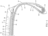
- Figure 1 illustrates a first embodiment of one half of a pneumatic tire 10, suitable for use as a truck tire.
- the tire 10 has a tread 12 with a non-skid depth D.
- the tire tread 12 may comprise a plurality of circumferentially continuous ribs, which may vary, but are shown for example as ribs 31, 32 and 33. Positioned between each rib is a circumferential groove 34, 35, 36, which are preferably continuous.
- the tread may also comprise optional sipes (not shown).
- the tread pattern is not limited to same, and may comprise, for example, a plurality of blocks and grooves (not shown).
- the tire 10 further comprises a casing 14 which includes two opposed sidewalls 16 which extend down from the tread 12 to the bead area.
- the casing of the tire may optionally include an inner liner 24 which is typically formed of halobutyl rubber which forms an air impervious barrier.
- the tire casing 14 further includes one or more radial plies 18 extending from the tread, down the sidewall to the tire bead 20.
- the radial ply 18 is wrapped about or otherwise secured to each annular bead 20.
- the beads 20 may be any desired shape, but in this embodiment, it is shown as a hexagonal configuration with steel filaments.
- the tire may further optionally include an apex 21 which may be shaped like a triangle.
- the ply turnup in the bead area may be optionally reinforced with a chipper 23 wrapped about the bead ply 18.
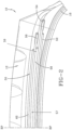
- the tire 10 further includes a belt package 50 which is located between the tread 12 and the one or more plies 18.
- the belt package may comprise one or more layers of reinforcement.
- the ply 18 and the belt reinforcing structure 50 are made from cord reinforced elastomeric material, wherein the cords are typically steel wire or polyamide filaments and the elastomer preferably being rubber.
- the belt reinforcing package 50 may include an optional transitional belt 52 that is the radially innermost belt of the belt package 50.
- the transition belt 52 preferably has an axial belt width in a range of from 60% to 90% of the tread arc width.
- the transition belt 52 preferably has an orientation that has an angle of between 45 to 70 degrees (preferably right).
- the transition belt 52 is preferably made of ultra tensile steel with a construction of 3+2x0.35 UT.
- Belt reinforcing structure 50 further includes a first extensible working belt 54 and a second extensible working belt 56.
- the first working belt 54 is located radially inwards of the second working belt 56.
- the first working belt 54 has an axial belt width substantially equal to the tread arc width and is preferably the widest belt of the belt package 50.
- the breaker angle of first working belt 54 is between 10 and 50 degrees, preferably with a right orientation, more preferably in the range of from 10 to 45 degrees or in the range of from 12 to 50 degrees.
- the first working belt 54 preferably comprises extensible or high elongation wire as cord reinforcement having a % elongation at 10% of breaking load of greater than 0.2%, as measured from a cord taken from a cured tire.
- the % elongation at the 10% of breaking load is greater than 0.4 %, and more preferably greater than 0.8%, and most preferably greater than 1.2%.
- the first working belt construction is preferably formed of wire having a wire construction of 3x7x, 3x4x, 4x4x.
- the EPI ends per 2.54 cm" preferably range from 8 to 14.
- the second working belt 56 is located radially outward of the first working belt, and preferably has an axial width less than the width of first working belt 54.
- the second working belt 56 has a width less than the axial width of the first working belt 54 by a step off, which preferably ranges from 10 to 20 mm.
- the second working belt 56 has a breaker angle between 10 to 50 degrees, and more preferably in the range of 16 to 30 degrees, preferably with a left orientation, and more preferably in the range of from 19 to 25 degrees.
- the angle of the first working belt 54 is different from the angle of the second working belt 56.
- the angle of either the first or second working belt 54, 56 is the angle of the parallel reinforcement cords relative to the circumferential direction of the tire 10.
- the angle of the first working belt ⁇ 1 is greater than the angle of the second working belt ⁇ 2 .
- is greater than 5 degrees.
- the second working belt 56 preferably comprises extensible or high elongation wire as cord reinforcement preferably having the same construction with the same but opposite angular orientation as the first working belt 54.
- the tensile strength measurements on the working belts 54, 56 such as the load at break (maximum load in N), strength at break (in MPa) and elongation at break (total elongation in %) are performed in tension in accordance with ISO 6892-1 B (2019) at a pre-load no more than 25 MPa tested on a cable or wire when taken from a cured tire.
- the belt structure 50 further comprises a relatively low angle belt 58 which is preferably located between the first and second working belts 54, 56.
- the relatively low angle belt 58 may also be located between the transition belt 52 and the first working belt 54, or radially outward of the second working belt 56.
- the relatively low angle belt 58 has reinforcements that are oriented circumferentially at 5 degrees or less, preferably 2 degrees or less such as 0.5 degrees or 0 degrees.
- the relatively low angle belt 58 is preferably formed from spirally winding a rubberized strip of one or more cords.
- the strip has 1-4 steel cords and has a strip width less than 15 mm such as 5 mm or 5 mm to 10 mm.
- the relatively low angle belt 58 may be formed of a cut belt with the reinforcements oriented in the range of 0 to 10 degrees from the circumferential direction, or more preferably in the range of 0 to 5 degrees from the circumferential direction.
- the relatively low angle belt 58 has a width sized to avoid compression in the shoulder area.
- the axial belt width of the relatively low angle belt 58 is preferably less than the axial belt width of the first and second working belts 54, 56 and is preferably wider than the top protector belt 62.
- the relatively low angle belt 58 preferably comprises reinforcement cords, preferably steel wire cords, of a 3x7 construction, a 3x4 construction, or a 4x4 construction. More preferably, the reinforcement cords are steel wire cords of a 3x7x0.22 construction, a 3x4x0.26 construction, or a 4x4x0.22 construction, and preferably formed of high tensile steel.
- the reinforcement cords of the relatively low angle belt 58 are extensible.
- the % elongation at 10% of breaking load is 0.2 or more, and preferably 0.4 % or more, and more preferably 0.6% or more, and most preferably 0.8%.
- the relatively low angle belt may be formed of non-metal reinforcements such as aramid, carbon fiber, or polyketone or POK.
- the tensile measurements such as the load at break (maximum load in N), strength at break (in MPa) and elongation at break (total elongation in %) are performed in tension in accordance with ISO 6892-1 B (2019) at a pre-load no more than 10 MPa tested on a cable or wire when taken from a cured tire.
- the relatively low angle belt 58 has a central portion 57 located between the two outer lateral ends 59.
- the central portion 57 of the relatively low angle belt 58 has an axial width in the range of from 40% to 60% of the total relatively low angle belt width, and more preferably about 50% or 45% to 55% of the total relatively low angle belt width.
- the reinforcement cords of the relatively low angle belt are typically coated with a rubber compound before layup. During cure or vulcanization, the rubber penetrates the cord.
- the degree to which the rubber penetrates the free zones of a cord (called rubber penetration) is expressed as a percentage of the free zones occupied by a rubber compound after curing and is determined by an air-permeability test. This test is performed on cords extracted directly from the relatively low angle belt 58 of a cured tire which has therefore been penetrated with the cured rubber compound.
- the air permeability test is run as per protocol described in: L. BOURGOIS, Survey of Mechanical Properties of Steel Cord and Related Test Methods, Special Technical Publication 694, ASTM, 1980 .
- the rubber penetration at the outer lateral ends 59 of the relatively low angle belt 58 can be set to be either equal to, or less than, the rubber penetration at the central portion 59. Preferably, it is less than the rubber penetration at the central portion 59 such as 95% at the axially outer ends 57 and 45 % at the central portion.
- the rubber penetration at the outer lateral ends 57 of the relatively low angle belt 58 was determined to be greater than the rubber penetration at the central portion 59.
- the rubber penetration at the outer lateral ends 57 was in a range of from 90% to 100%, while the rubber penetration at the central portion 59 was 50% or less.
- the belt structure further includes a top protector belt 62 that is the radially outermost belt.
- the top protector belt 62 preferably has a width that is in the range of from 80% to 85% of the width of the relatively low angle belt 58.
- the belt 62 has the same angle and orientation as the adjacent working belt 56.
- the top protector belt 62 preferably has reinforcement cords made of high impact steel cord wherein the cord preferably has full rubber penetration, i.e., at least 90% up to 100%, that helps in avoiding corrosion and enable excellent retreadability. It also provides high impact resistance as it exhibits more work to break because of its enhanced % elongation (> 5%) even after embedded in rubber.
- the reinforcement cords of the top protector belt 62 have a cord construction of 5x, and more preferably, 5x0.35 or 5x0.38.
- the reinforcement cords of the top protector belt 62 are preferably made of steel, and are high impact cords (HI), with a very high energy absorption with energy/cord > 7.5 J/mm2, using a Charpy Impact Tester in a 2.54 cm strip with 10 EPI (ends per 2.54 cm).
- HI high impact cords
- Having a top protective belt with a high impact cord helps in absorbing the shock created during an impact and relieves the stresses on the tread shoulder grooves.
- the aspect ratio of the tire described above may vary.
- the aspect ratio is preferably in the range of 50 to 90.
- the tire preferably has a net to gross ratio in the range of 70 to 90, more preferably in the range of from 74 to 86 or from 78 to 84.
- the tire in accordance with the invention has improved shock absorbing characteristics during an impact and an improved stress relieve, in particular on the tread shoulder grooves. This leads to an improved crown durability and increased load carrying capacity.
- the tire also shows an excellent retreadability and improved corrosion resistance.
Landscapes
- Engineering & Computer Science (AREA)
- Mechanical Engineering (AREA)
- Tires In General (AREA)
Claims (15)
- Luftreifen zur Verwendung auf Lastkraftwagen, wobei der Reifen (10) eine Lauffläche (12) und eine Gürtelstruktur (50) aufweist, die radial innerhalb der Lauffläche (10) angeordnet ist, wobei die Gürtelstruktur (50) einen ersten Arbeitsgürtel (54) und einen zweiten Arbeitsgürtel (56) aufweist, wobei der Winkel des ersten und des zweiten Arbeitsgürtels (54, 56) jeweils im Bereich von 10 Grad bis 50 Grad liegt, gemessen relativ zur Umfangsrichtung des Reifens (10), und wobei der Winkel des ersten Arbeitsgürtels (54) größer ist als der Winkel des zweiten Arbeitsgürtels (56), wobei die Gürtelstruktur (50) ferner einen Gürtel (58) mit relativ niedrigem Winkel umfasst, der Verstärkungen aufweist, die um weniger als 5 Grad relativ zur Umfangsrichtung des Reifens (10) abgewinkelt sind, wobei der Gürtel (58) mit relativ niedrigem Winkel dehnbare Verstärkungskorde aufweist, d. h. Korde, die eine relative Dehnbarkeit von mehr als 0,2 % bei 10 % der Bruchlast aufweisen, die an einem aus einem vulkanisierten Reifen gezogenen Kord gemessen wird, dadurch gekennzeichnet, dass der Reifen (10) ferner einen radial äußersten oberen Schutzgürtel (62) enthält, der Verstärkungskorde umfasst, die eine Aufprallenergieabsorption von > 7,5 J/mm2 aufweisen, die mit einem Charpy Impact Tester in einem 2,54 cm langen Streifen mit 10 Enden pro 2,54 cm gemessen wird, und wobei die Kautschukdurchdringung an den äußeren seitlichen Enden (59) des Gürtels (58) mit relativ niedrigem Winkel größer ist als die Kautschukdurchdringung in einem mittleren Abschnitt (57) des Gürtels (58) mit relativ niedrigem Winkel.
- Reifen nach Anspruch 1, wobei die dehnbaren Verstärkungskorde des Gürtels (58) mit relativ niedrigem Winkel eine 4x4x0,22-Kordkonstruktion aufweisen.
- Luftreifen nach Anspruch 1, wobei der erste und der zweite Arbeitsgürtel (54, 56) jeweils dehnbare Verstärkungskorde aufweisen.
- Luftreifen nach Anspruch 1, wobei der Reifen (10) den oben genannten oberen Schutzgürtel (62) aufweist, der radial außerhalb des oben genannten ersten und zweiten Arbeitsgürtels (54, 56) angeordnet ist; und wobei der obere Schutzgürtel (62) eine Breite von mehr als 50% der Laufflächenbreite und/oder eine Breite aufweist, die geringer ist als die axialen Breiten jedes der Arbeitsgürtel (54, 56).
- Reifen nach mindestens einem der vorhergehenden Ansprüche, wobei der Absolutwert der Differenz zwischen dem Gürtelwinkel des ersten Arbeitsgürtels (54) minus dem Gürtelwinkel des zweiten Arbeitsgürtels (56) größer als 5 Grad ist.
- Reifen nach mindestens einem der vorhergehenden Ansprüche, wobei der erste und der zweite Arbeitsgürtel (54, 56) eine Drahtverstärkung, die eine prozentuale Dehnung bei 10 % der Bruchlast von mehr als 0,2 %, alternativ von mehr als 0,4 %, aufweist, wenn sie von einem Draht aus einem vulkanisierten Reifen genommen wird.
- Reifen nach mindestens einem der vorhergehenden Ansprüche, wobei der Gürtel (58) mit relativ niedrigem Winkel eine Drahtverstärkung umfasst, die eine prozentuale Dehnung bei 10 % der Bruchlast von mehr als 0,4 % oder mehr als 0,8 % oder mehr als 1,2 % aufweist, wenn sie von einem Draht aus einem vulkanisierten Reifen genommen wird.
- Reifen nach mindestens einem der vorhergehenden Ansprüche, wobei der Gürtel (58) mit relativ niedrigem Winkel eine Breite aufweist, die größer ist als die Breite eines oberen Gürtels oder des oberen Schutzgürtels (62).
- Reifen nach Anspruch 1, wobei die Kautschukdurchdringung an beiden äußeren seitlichen Enden (59) des Gürtels (58) mit relativ niedrigem Winkel größer als 90 % ist oder in einem Bereich von 90 % bis 100 % liegt.
- Reifen nach mindestens einem der vorhergehenden Ansprüche, wobei die Kautschukdurchdringung an dem mittleren Abschnitt (57) des Gürtels (58) mit relativ niedrigem Winkel weniger als 50 % beträgt.
- Reifen nach Anspruch 1, 9 oder 10, wobei der oben genannte mittlere Abschnitt (57) des Gürtels (58) mit relativ geringem Winkel zwischen den oben genannten beiden äußeren seitlichen Enden (59) des Gürtels (58) mit relativ geringem Winkel angeordnet ist, wobei der mittlere Abschnitt (57) eine axiale Breite im Bereich von 40 % bis 60 % der gesamten axialen Breite des Gürtels mit relativ geringem Winkel aufweist, vorzugsweise etwa 50 % oder 45 % bis 55 % der gesamten axialen Breite des Gürtels mit relativ geringem Winkel, und die beiden äußeren seitlichen Enden (59) jeweils eine axiale Breite in einem Bereich von 5 % bis 30 %, vorzugsweise 10 % bis 25 %, der gesamten axialen Breite des Gürtels mit relativ geringem Winkel aufweisen.
- Reifen nach mindestens einem der vorhergehenden Ansprüche, wobei der Gürtel (58) mit relativ niedrigem Winkel zwischen dem ersten und zweiten Arbeitsgürtel (54, 56) angeordnet ist.
- Reifen nach mindestens einem der vorhergehenden Ansprüche, wobei die Gürtelstruktur (50) ferner einen Übergangsgürtel (52) als den radial innersten Gürtel des Gürtelpakets (50) aufweist.
- Reifen nach mindestens einem der vorhergehenden Ansprüche, wobei der erste und der zweite Arbeitsgürtel (54, 56) jeweils Drahtverstärkungskorde mit einer 3x7x, einer 3x4x, einer 4x4x oder einer 4+3x Konstruktion aufweisen.
- Reifen nach mindestens einem der vorhergehenden Ansprüche, wobei der Gürtel (58) mit relativ niedrigem Winkel eine Drahtverstärkung mit einer 3x7, 3x4 oder 4x4 Konstruktion aufweist.
Applications Claiming Priority (2)
| Application Number | Priority Date | Filing Date | Title |
|---|---|---|---|
| US202063072592P | 2020-08-31 | 2020-08-31 | |
| US17/120,346 US20220063352A1 (en) | 2020-08-31 | 2020-12-14 | Truck tire |
Publications (2)
| Publication Number | Publication Date |
|---|---|
| EP4011645A1 EP4011645A1 (de) | 2022-06-15 |
| EP4011645B1 true EP4011645B1 (de) | 2024-12-18 |
Family
ID=80356338
Family Applications (1)
| Application Number | Title | Priority Date | Filing Date |
|---|---|---|---|
| EP21211342.7A Active EP4011645B1 (de) | 2020-08-31 | 2021-11-30 | Lastwagenreifen |
Country Status (3)
| Country | Link |
|---|---|
| US (1) | US20220063352A1 (de) |
| EP (1) | EP4011645B1 (de) |
| CN (1) | CN114619804A (de) |
Families Citing this family (2)
| Publication number | Priority date | Publication date | Assignee | Title |
|---|---|---|---|---|
| JP2024081509A (ja) * | 2022-12-06 | 2024-06-18 | 株式会社ブリヂストン | 空気入りタイヤ |
| US20260027854A1 (en) * | 2024-07-29 | 2026-01-29 | The Goodyear Tire & Rubber Company | Truck tire |
Family Cites Families (16)
| Publication number | Priority date | Publication date | Assignee | Title |
|---|---|---|---|---|
| EP0342644B1 (de) * | 1988-05-20 | 1996-08-21 | TOYO TIRE & RUBBER CO., LTD . | Luftreifen |
| JP3434100B2 (ja) * | 1995-10-06 | 2003-08-04 | 住友ゴム工業株式会社 | 重荷重用タイヤ |
| JP3602618B2 (ja) * | 1995-09-01 | 2004-12-15 | 住友ゴム工業株式会社 | タイヤ用のスチールコード |
| DE69807705T2 (de) * | 1997-07-29 | 2003-01-02 | Bekaert N.V., Zwevegem | Stahlseil für schutzlagen von luftreifen |
| JP3759292B2 (ja) * | 1997-08-06 | 2006-03-22 | 株式会社ブリヂストン | ゴム物品補強用スチールコード及び空気入りタイヤ |
| US7404425B2 (en) * | 2002-04-24 | 2008-07-29 | The Goodyear Tire & Rubber Company | Belt package for super single truck tires |
| PL2218589T3 (pl) * | 2007-11-27 | 2013-01-31 | Bridgestone Corp | Radialna opona pneumatyczna |
| US9168789B2 (en) * | 2008-12-19 | 2015-10-27 | The Goodyear Tire & Rubber Company | Truck tire |
| DE102010000471A1 (de) * | 2010-02-19 | 2011-08-25 | Continental Reifen Deutschland GmbH, 30165 | Fahrzeugluftreifen |
| US20120067491A1 (en) * | 2010-09-22 | 2012-03-22 | Mahmoud Cherif Assaad | Tires with high strength reinforcement |
| DE102010061330A1 (de) * | 2010-12-17 | 2012-06-21 | Continental Reifen Deutschland Gmbh | Fahrzeugluftreifen |
| JP5525073B1 (ja) * | 2013-02-06 | 2014-06-18 | 株式会社ブリヂストン | 重荷重用タイヤ |
| BR112016001155B1 (pt) * | 2013-08-01 | 2022-02-08 | Nv Bekaert Sa | Cabo de aço e pneumático |
| FR3051397B1 (fr) * | 2016-05-20 | 2018-05-11 | Compagnie Generale Des Etablissements Michelin | Pneumatique presentant une couche de protection avec des proprietes d’endurance ameliorees |
| JP6870451B2 (ja) * | 2017-04-14 | 2021-05-12 | 横浜ゴム株式会社 | スチールコード及びそれを用いた空気入りラジアルタイヤ |
| DE102018214913A1 (de) * | 2018-09-03 | 2020-03-05 | Continental Reifen Deutschland Gmbh | Nutzfahrzeugreifen |
-
2020
- 2020-12-14 US US17/120,346 patent/US20220063352A1/en not_active Abandoned
-
2021
- 2021-11-30 EP EP21211342.7A patent/EP4011645B1/de active Active
- 2021-12-14 CN CN202111524491.6A patent/CN114619804A/zh active Pending
Also Published As
| Publication number | Publication date |
|---|---|
| US20220063352A1 (en) | 2022-03-03 |
| CN114619804A (zh) | 2022-06-14 |
| EP4011645A1 (de) | 2022-06-15 |
Similar Documents
| Publication | Publication Date | Title |
|---|---|---|
| CN102257210B (zh) | 包括低渗透性的胎体增强件帘线和与胎体增强件相关联的纺织丝线的轮胎 | |
| EP2199104B1 (de) | Lastwagenreifen | |
| EP3838623B1 (de) | Lastwagenreifen | |
| EP4011645B1 (de) | Lastwagenreifen | |
| EP4144539B1 (de) | Luftreifen zur verwendung auf einem lastwagen | |
| EP4011646B1 (de) | Lastwagenreifen | |
| US20220185034A1 (en) | Tire with improved bead structure | |
| EP3960496A1 (de) | Lastwagenreifen | |
| EP4197815B1 (de) | Lastwagenreifen | |
| EP4197813B1 (de) | Lastwagenreifen | |
| EP3838621B1 (de) | Luftreifen | |
| EP4011647B1 (de) | Lastwagenreifen | |
| US20220185035A1 (en) | Tire with improved bead structure | |
| AU2021403914A9 (en) | Optimised architecture of a civil engineering tyre | |
| EP4197814B1 (de) | Lastwagenreifen | |
| AU2004202089A1 (en) | Two Piece Tire with Improved Tire Tread Belt | |
| BR102021024569A2 (pt) | Pneu de caminhão | |
| US20130118670A1 (en) | Pneumatic tire with tackified wrapped reinforcement | |
| BR102021024569B1 (pt) | Pneu para uso em caminhões |
Legal Events
| Date | Code | Title | Description |
|---|---|---|---|
| PUAI | Public reference made under article 153(3) epc to a published international application that has entered the european phase |
Free format text: ORIGINAL CODE: 0009012 |
|
| STAA | Information on the status of an ep patent application or granted ep patent |
Free format text: STATUS: THE APPLICATION HAS BEEN PUBLISHED |
|
| AK | Designated contracting states |
Kind code of ref document: A1 Designated state(s): AL AT BE BG CH CY CZ DE DK EE ES FI FR GB GR HR HU IE IS IT LI LT LU LV MC MK MT NL NO PL PT RO RS SE SI SK SM TR |
|
| STAA | Information on the status of an ep patent application or granted ep patent |
Free format text: STATUS: REQUEST FOR EXAMINATION WAS MADE |
|
| 17P | Request for examination filed |
Effective date: 20221215 |
|
| RBV | Designated contracting states (corrected) |
Designated state(s): AL AT BE BG CH CY CZ DE DK EE ES FI FR GB GR HR HU IE IS IT LI LT LU LV MC MK MT NL NO PL PT RO RS SE SI SK SM TR |
|
| GRAP | Despatch of communication of intention to grant a patent |
Free format text: ORIGINAL CODE: EPIDOSNIGR1 |
|
| STAA | Information on the status of an ep patent application or granted ep patent |
Free format text: STATUS: GRANT OF PATENT IS INTENDED |
|
| INTG | Intention to grant announced |
Effective date: 20240712 |
|
| GRAS | Grant fee paid |
Free format text: ORIGINAL CODE: EPIDOSNIGR3 |
|
| GRAA | (expected) grant |
Free format text: ORIGINAL CODE: 0009210 |
|
| STAA | Information on the status of an ep patent application or granted ep patent |
Free format text: STATUS: THE PATENT HAS BEEN GRANTED |
|
| AK | Designated contracting states |
Kind code of ref document: B1 Designated state(s): AL AT BE BG CH CY CZ DE DK EE ES FI FR GB GR HR HU IE IS IT LI LT LU LV MC MK MT NL NO PL PT RO RS SE SI SK SM TR |
|
| REG | Reference to a national code |
Ref country code: CH Ref legal event code: EP |
|
| REG | Reference to a national code |
Ref country code: DE Ref legal event code: R096 Ref document number: 602021023506 Country of ref document: DE |
|
| REG | Reference to a national code |
Ref country code: IE Ref legal event code: FG4D |
|
| REG | Reference to a national code |
Ref country code: LT Ref legal event code: MG9D |
|
| PG25 | Lapsed in a contracting state [announced via postgrant information from national office to epo] |
Ref country code: HR Free format text: LAPSE BECAUSE OF FAILURE TO SUBMIT A TRANSLATION OF THE DESCRIPTION OR TO PAY THE FEE WITHIN THE PRESCRIBED TIME-LIMIT Effective date: 20241218 |
|
| PG25 | Lapsed in a contracting state [announced via postgrant information from national office to epo] |
Ref country code: FI Free format text: LAPSE BECAUSE OF FAILURE TO SUBMIT A TRANSLATION OF THE DESCRIPTION OR TO PAY THE FEE WITHIN THE PRESCRIBED TIME-LIMIT Effective date: 20241218 |
|
| PG25 | Lapsed in a contracting state [announced via postgrant information from national office to epo] |
Ref country code: BG Free format text: LAPSE BECAUSE OF FAILURE TO SUBMIT A TRANSLATION OF THE DESCRIPTION OR TO PAY THE FEE WITHIN THE PRESCRIBED TIME-LIMIT Effective date: 20241218 |
|
| PG25 | Lapsed in a contracting state [announced via postgrant information from national office to epo] |
Ref country code: NO Free format text: LAPSE BECAUSE OF FAILURE TO SUBMIT A TRANSLATION OF THE DESCRIPTION OR TO PAY THE FEE WITHIN THE PRESCRIBED TIME-LIMIT Effective date: 20250318 |
|
| REG | Reference to a national code |
Ref country code: NL Ref legal event code: MP Effective date: 20241218 |
|
| PG25 | Lapsed in a contracting state [announced via postgrant information from national office to epo] |
Ref country code: LV Free format text: LAPSE BECAUSE OF FAILURE TO SUBMIT A TRANSLATION OF THE DESCRIPTION OR TO PAY THE FEE WITHIN THE PRESCRIBED TIME-LIMIT Effective date: 20241218 Ref country code: GR Free format text: LAPSE BECAUSE OF FAILURE TO SUBMIT A TRANSLATION OF THE DESCRIPTION OR TO PAY THE FEE WITHIN THE PRESCRIBED TIME-LIMIT Effective date: 20250319 |
|
| PG25 | Lapsed in a contracting state [announced via postgrant information from national office to epo] |
Ref country code: RS Free format text: LAPSE BECAUSE OF FAILURE TO SUBMIT A TRANSLATION OF THE DESCRIPTION OR TO PAY THE FEE WITHIN THE PRESCRIBED TIME-LIMIT Effective date: 20250318 |
|
| PG25 | Lapsed in a contracting state [announced via postgrant information from national office to epo] |
Ref country code: NL Free format text: LAPSE BECAUSE OF FAILURE TO SUBMIT A TRANSLATION OF THE DESCRIPTION OR TO PAY THE FEE WITHIN THE PRESCRIBED TIME-LIMIT Effective date: 20241218 |
|
| REG | Reference to a national code |
Ref country code: AT Ref legal event code: MK05 Ref document number: 1751984 Country of ref document: AT Kind code of ref document: T Effective date: 20241218 |
|
| PG25 | Lapsed in a contracting state [announced via postgrant information from national office to epo] |
Ref country code: SM Free format text: LAPSE BECAUSE OF FAILURE TO SUBMIT A TRANSLATION OF THE DESCRIPTION OR TO PAY THE FEE WITHIN THE PRESCRIBED TIME-LIMIT Effective date: 20241218 |
|
| PG25 | Lapsed in a contracting state [announced via postgrant information from national office to epo] |
Ref country code: PL Free format text: LAPSE BECAUSE OF FAILURE TO SUBMIT A TRANSLATION OF THE DESCRIPTION OR TO PAY THE FEE WITHIN THE PRESCRIBED TIME-LIMIT Effective date: 20241218 |
|
| PG25 | Lapsed in a contracting state [announced via postgrant information from national office to epo] |
Ref country code: ES Free format text: LAPSE BECAUSE OF FAILURE TO SUBMIT A TRANSLATION OF THE DESCRIPTION OR TO PAY THE FEE WITHIN THE PRESCRIBED TIME-LIMIT Effective date: 20241218 |
|
| PG25 | Lapsed in a contracting state [announced via postgrant information from national office to epo] |
Ref country code: IS Free format text: LAPSE BECAUSE OF FAILURE TO SUBMIT A TRANSLATION OF THE DESCRIPTION OR TO PAY THE FEE WITHIN THE PRESCRIBED TIME-LIMIT Effective date: 20250418 |
|
| PG25 | Lapsed in a contracting state [announced via postgrant information from national office to epo] |
Ref country code: PT Free format text: LAPSE BECAUSE OF FAILURE TO SUBMIT A TRANSLATION OF THE DESCRIPTION OR TO PAY THE FEE WITHIN THE PRESCRIBED TIME-LIMIT Effective date: 20250421 |
|
| PG25 | Lapsed in a contracting state [announced via postgrant information from national office to epo] |
Ref country code: EE Free format text: LAPSE BECAUSE OF FAILURE TO SUBMIT A TRANSLATION OF THE DESCRIPTION OR TO PAY THE FEE WITHIN THE PRESCRIBED TIME-LIMIT Effective date: 20241218 |
|
| PG25 | Lapsed in a contracting state [announced via postgrant information from national office to epo] |
Ref country code: AT Free format text: LAPSE BECAUSE OF FAILURE TO SUBMIT A TRANSLATION OF THE DESCRIPTION OR TO PAY THE FEE WITHIN THE PRESCRIBED TIME-LIMIT Effective date: 20241218 Ref country code: RO Free format text: LAPSE BECAUSE OF FAILURE TO SUBMIT A TRANSLATION OF THE DESCRIPTION OR TO PAY THE FEE WITHIN THE PRESCRIBED TIME-LIMIT Effective date: 20241218 |
|
| PG25 | Lapsed in a contracting state [announced via postgrant information from national office to epo] |
Ref country code: SK Free format text: LAPSE BECAUSE OF FAILURE TO SUBMIT A TRANSLATION OF THE DESCRIPTION OR TO PAY THE FEE WITHIN THE PRESCRIBED TIME-LIMIT Effective date: 20241218 |
|
| PG25 | Lapsed in a contracting state [announced via postgrant information from national office to epo] |
Ref country code: CZ Free format text: LAPSE BECAUSE OF FAILURE TO SUBMIT A TRANSLATION OF THE DESCRIPTION OR TO PAY THE FEE WITHIN THE PRESCRIBED TIME-LIMIT Effective date: 20241218 |
|
| PG25 | Lapsed in a contracting state [announced via postgrant information from national office to epo] |
Ref country code: SE Free format text: LAPSE BECAUSE OF FAILURE TO SUBMIT A TRANSLATION OF THE DESCRIPTION OR TO PAY THE FEE WITHIN THE PRESCRIBED TIME-LIMIT Effective date: 20241218 |
|
| REG | Reference to a national code |
Ref country code: DE Ref legal event code: R097 Ref document number: 602021023506 Country of ref document: DE |
|
| PG25 | Lapsed in a contracting state [announced via postgrant information from national office to epo] |
Ref country code: DK Free format text: LAPSE BECAUSE OF FAILURE TO SUBMIT A TRANSLATION OF THE DESCRIPTION OR TO PAY THE FEE WITHIN THE PRESCRIBED TIME-LIMIT Effective date: 20241218 |
|
| PLBE | No opposition filed within time limit |
Free format text: ORIGINAL CODE: 0009261 |
|
| STAA | Information on the status of an ep patent application or granted ep patent |
Free format text: STATUS: NO OPPOSITION FILED WITHIN TIME LIMIT |
|
| 26N | No opposition filed |
Effective date: 20250919 |
|
| PGFP | Annual fee paid to national office [announced via postgrant information from national office to epo] |
Ref country code: DE Payment date: 20251022 Year of fee payment: 5 |
|
| PGFP | Annual fee paid to national office [announced via postgrant information from national office to epo] |
Ref country code: GB Payment date: 20251023 Year of fee payment: 5 |
|
| PGFP | Annual fee paid to national office [announced via postgrant information from national office to epo] |
Ref country code: IT Payment date: 20251022 Year of fee payment: 5 |
|
| PGFP | Annual fee paid to national office [announced via postgrant information from national office to epo] |
Ref country code: FR Payment date: 20251023 Year of fee payment: 5 |
|
| PGFP | Annual fee paid to national office [announced via postgrant information from national office to epo] |
Ref country code: TR Payment date: 20251031 Year of fee payment: 5 |