EP4197579B1 - Conduit headgear connector for patient interface - Google Patents
Conduit headgear connector for patient interface Download PDFInfo
- Publication number
- EP4197579B1 EP4197579B1 EP22203609.7A EP22203609A EP4197579B1 EP 4197579 B1 EP4197579 B1 EP 4197579B1 EP 22203609 A EP22203609 A EP 22203609A EP 4197579 B1 EP4197579 B1 EP 4197579B1
- Authority
- EP
- European Patent Office
- Prior art keywords
- patient
- conduit connector
- patient interface
- conduit
- plenum chamber
- Prior art date
- Legal status (The legal status is an assumption and is not a legal conclusion. Google has not performed a legal analysis and makes no representation as to the accuracy of the status listed.)
- Active
Links
Images


Classifications
-
- A—HUMAN NECESSITIES
- A61—MEDICAL OR VETERINARY SCIENCE; HYGIENE
- A61M—DEVICES FOR INTRODUCING MEDIA INTO, OR ONTO, THE BODY; DEVICES FOR TRANSDUCING BODY MEDIA OR FOR TAKING MEDIA FROM THE BODY; DEVICES FOR PRODUCING OR ENDING SLEEP OR STUPOR
- A61M16/00—Devices for influencing the respiratory system of patients by gas treatment, e.g. ventilators; Tracheal tubes
- A61M16/06—Respiratory or anaesthetic masks
-
- A—HUMAN NECESSITIES
- A61—MEDICAL OR VETERINARY SCIENCE; HYGIENE
- A61M—DEVICES FOR INTRODUCING MEDIA INTO, OR ONTO, THE BODY; DEVICES FOR TRANSDUCING BODY MEDIA OR FOR TAKING MEDIA FROM THE BODY; DEVICES FOR PRODUCING OR ENDING SLEEP OR STUPOR
- A61M16/00—Devices for influencing the respiratory system of patients by gas treatment, e.g. ventilators; Tracheal tubes
- A61M16/0057—Pumps therefor
- A61M16/0066—Blowers or centrifugal pumps
- A61M16/0069—Blowers or centrifugal pumps the speed thereof being controlled by respiratory parameters, e.g. by inhalation
-
- A—HUMAN NECESSITIES
- A61—MEDICAL OR VETERINARY SCIENCE; HYGIENE
- A61M—DEVICES FOR INTRODUCING MEDIA INTO, OR ONTO, THE BODY; DEVICES FOR TRANSDUCING BODY MEDIA OR FOR TAKING MEDIA FROM THE BODY; DEVICES FOR PRODUCING OR ENDING SLEEP OR STUPOR
- A61M16/00—Devices for influencing the respiratory system of patients by gas treatment, e.g. ventilators; Tracheal tubes
- A61M16/06—Respiratory or anaesthetic masks
- A61M16/0605—Means for improving the adaptation of the mask to the patient
- A61M16/0616—Means for improving the adaptation of the mask to the patient with face sealing means comprising a flap or membrane projecting inwards, such that sealing increases with increasing inhalation gas pressure
-
- A—HUMAN NECESSITIES
- A61—MEDICAL OR VETERINARY SCIENCE; HYGIENE
- A61M—DEVICES FOR INTRODUCING MEDIA INTO, OR ONTO, THE BODY; DEVICES FOR TRANSDUCING BODY MEDIA OR FOR TAKING MEDIA FROM THE BODY; DEVICES FOR PRODUCING OR ENDING SLEEP OR STUPOR
- A61M16/00—Devices for influencing the respiratory system of patients by gas treatment, e.g. ventilators; Tracheal tubes
- A61M16/06—Respiratory or anaesthetic masks
- A61M16/0605—Means for improving the adaptation of the mask to the patient
- A61M16/0633—Means for improving the adaptation of the mask to the patient with forehead support
-
- A—HUMAN NECESSITIES
- A61—MEDICAL OR VETERINARY SCIENCE; HYGIENE
- A61M—DEVICES FOR INTRODUCING MEDIA INTO, OR ONTO, THE BODY; DEVICES FOR TRANSDUCING BODY MEDIA OR FOR TAKING MEDIA FROM THE BODY; DEVICES FOR PRODUCING OR ENDING SLEEP OR STUPOR
- A61M16/00—Devices for influencing the respiratory system of patients by gas treatment, e.g. ventilators; Tracheal tubes
- A61M16/06—Respiratory or anaesthetic masks
- A61M16/0666—Nasal cannulas or tubing
-
- A—HUMAN NECESSITIES
- A61—MEDICAL OR VETERINARY SCIENCE; HYGIENE
- A61M—DEVICES FOR INTRODUCING MEDIA INTO, OR ONTO, THE BODY; DEVICES FOR TRANSDUCING BODY MEDIA OR FOR TAKING MEDIA FROM THE BODY; DEVICES FOR PRODUCING OR ENDING SLEEP OR STUPOR
- A61M16/00—Devices for influencing the respiratory system of patients by gas treatment, e.g. ventilators; Tracheal tubes
- A61M16/06—Respiratory or anaesthetic masks
- A61M16/0683—Holding devices therefor
-
- A—HUMAN NECESSITIES
- A61—MEDICAL OR VETERINARY SCIENCE; HYGIENE
- A61M—DEVICES FOR INTRODUCING MEDIA INTO, OR ONTO, THE BODY; DEVICES FOR TRANSDUCING BODY MEDIA OR FOR TAKING MEDIA FROM THE BODY; DEVICES FOR PRODUCING OR ENDING SLEEP OR STUPOR
- A61M16/00—Devices for influencing the respiratory system of patients by gas treatment, e.g. ventilators; Tracheal tubes
- A61M16/08—Bellows; Connecting tubes ; Water traps; Patient circuits
- A61M16/0816—Joints or connectors
-
- A—HUMAN NECESSITIES
- A61—MEDICAL OR VETERINARY SCIENCE; HYGIENE
- A61M—DEVICES FOR INTRODUCING MEDIA INTO, OR ONTO, THE BODY; DEVICES FOR TRANSDUCING BODY MEDIA OR FOR TAKING MEDIA FROM THE BODY; DEVICES FOR PRODUCING OR ENDING SLEEP OR STUPOR
- A61M16/00—Devices for influencing the respiratory system of patients by gas treatment, e.g. ventilators; Tracheal tubes
- A61M16/08—Bellows; Connecting tubes ; Water traps; Patient circuits
- A61M16/0875—Connecting tubes
-
- A—HUMAN NECESSITIES
- A61—MEDICAL OR VETERINARY SCIENCE; HYGIENE
- A61M—DEVICES FOR INTRODUCING MEDIA INTO, OR ONTO, THE BODY; DEVICES FOR TRANSDUCING BODY MEDIA OR FOR TAKING MEDIA FROM THE BODY; DEVICES FOR PRODUCING OR ENDING SLEEP OR STUPOR
- A61M16/00—Devices for influencing the respiratory system of patients by gas treatment, e.g. ventilators; Tracheal tubes
- A61M16/10—Preparation of respiratory gases or vapours
- A61M16/14—Preparation of respiratory gases or vapours by mixing different fluids, one of them being in a liquid phase
- A61M16/16—Devices to humidify the respiration air
-
- A—HUMAN NECESSITIES
- A61—MEDICAL OR VETERINARY SCIENCE; HYGIENE
- A61M—DEVICES FOR INTRODUCING MEDIA INTO, OR ONTO, THE BODY; DEVICES FOR TRANSDUCING BODY MEDIA OR FOR TAKING MEDIA FROM THE BODY; DEVICES FOR PRODUCING OR ENDING SLEEP OR STUPOR
- A61M16/00—Devices for influencing the respiratory system of patients by gas treatment, e.g. ventilators; Tracheal tubes
- A61M16/20—Valves specially adapted to medical respiratory devices
- A61M16/208—Non-controlled one-way valves, e.g. exhalation, check, pop-off non-rebreathing valves
-
- A—HUMAN NECESSITIES
- A61—MEDICAL OR VETERINARY SCIENCE; HYGIENE
- A61M—DEVICES FOR INTRODUCING MEDIA INTO, OR ONTO, THE BODY; DEVICES FOR TRANSDUCING BODY MEDIA OR FOR TAKING MEDIA FROM THE BODY; DEVICES FOR PRODUCING OR ENDING SLEEP OR STUPOR
- A61M16/00—Devices for influencing the respiratory system of patients by gas treatment, e.g. ventilators; Tracheal tubes
- A61M16/0051—Devices for influencing the respiratory system of patients by gas treatment, e.g. ventilators; Tracheal tubes with alarm devices
-
- A—HUMAN NECESSITIES
- A61—MEDICAL OR VETERINARY SCIENCE; HYGIENE
- A61M—DEVICES FOR INTRODUCING MEDIA INTO, OR ONTO, THE BODY; DEVICES FOR TRANSDUCING BODY MEDIA OR FOR TAKING MEDIA FROM THE BODY; DEVICES FOR PRODUCING OR ENDING SLEEP OR STUPOR
- A61M16/00—Devices for influencing the respiratory system of patients by gas treatment, e.g. ventilators; Tracheal tubes
- A61M16/021—Devices for influencing the respiratory system of patients by gas treatment, e.g. ventilators; Tracheal tubes operated by electrical means
- A61M16/022—Control means therefor
- A61M16/024—Control means therefor including calculation means, e.g. using a processor
-
- A—HUMAN NECESSITIES
- A61—MEDICAL OR VETERINARY SCIENCE; HYGIENE
- A61M—DEVICES FOR INTRODUCING MEDIA INTO, OR ONTO, THE BODY; DEVICES FOR TRANSDUCING BODY MEDIA OR FOR TAKING MEDIA FROM THE BODY; DEVICES FOR PRODUCING OR ENDING SLEEP OR STUPOR
- A61M16/00—Devices for influencing the respiratory system of patients by gas treatment, e.g. ventilators; Tracheal tubes
- A61M16/06—Respiratory or anaesthetic masks
- A61M16/0605—Means for improving the adaptation of the mask to the patient
- A61M16/0611—Means for improving the adaptation of the mask to the patient with a gusset portion
-
- A—HUMAN NECESSITIES
- A61—MEDICAL OR VETERINARY SCIENCE; HYGIENE
- A61M—DEVICES FOR INTRODUCING MEDIA INTO, OR ONTO, THE BODY; DEVICES FOR TRANSDUCING BODY MEDIA OR FOR TAKING MEDIA FROM THE BODY; DEVICES FOR PRODUCING OR ENDING SLEEP OR STUPOR
- A61M16/00—Devices for influencing the respiratory system of patients by gas treatment, e.g. ventilators; Tracheal tubes
- A61M16/06—Respiratory or anaesthetic masks
- A61M16/0605—Means for improving the adaptation of the mask to the patient
- A61M16/0616—Means for improving the adaptation of the mask to the patient with face sealing means comprising a flap or membrane projecting inwards, such that sealing increases with increasing inhalation gas pressure
- A61M16/0622—Means for improving the adaptation of the mask to the patient with face sealing means comprising a flap or membrane projecting inwards, such that sealing increases with increasing inhalation gas pressure having an underlying cushion
-
- A—HUMAN NECESSITIES
- A61—MEDICAL OR VETERINARY SCIENCE; HYGIENE
- A61M—DEVICES FOR INTRODUCING MEDIA INTO, OR ONTO, THE BODY; DEVICES FOR TRANSDUCING BODY MEDIA OR FOR TAKING MEDIA FROM THE BODY; DEVICES FOR PRODUCING OR ENDING SLEEP OR STUPOR
- A61M16/00—Devices for influencing the respiratory system of patients by gas treatment, e.g. ventilators; Tracheal tubes
- A61M16/08—Bellows; Connecting tubes ; Water traps; Patient circuits
- A61M16/0816—Joints or connectors
- A61M16/0825—Joints or connectors with ball-sockets
-
- A—HUMAN NECESSITIES
- A61—MEDICAL OR VETERINARY SCIENCE; HYGIENE
- A61M—DEVICES FOR INTRODUCING MEDIA INTO, OR ONTO, THE BODY; DEVICES FOR TRANSDUCING BODY MEDIA OR FOR TAKING MEDIA FROM THE BODY; DEVICES FOR PRODUCING OR ENDING SLEEP OR STUPOR
- A61M16/00—Devices for influencing the respiratory system of patients by gas treatment, e.g. ventilators; Tracheal tubes
- A61M16/10—Preparation of respiratory gases or vapours
- A61M16/105—Filters
- A61M16/1055—Filters bacterial
-
- A—HUMAN NECESSITIES
- A61—MEDICAL OR VETERINARY SCIENCE; HYGIENE
- A61M—DEVICES FOR INTRODUCING MEDIA INTO, OR ONTO, THE BODY; DEVICES FOR TRANSDUCING BODY MEDIA OR FOR TAKING MEDIA FROM THE BODY; DEVICES FOR PRODUCING OR ENDING SLEEP OR STUPOR
- A61M16/00—Devices for influencing the respiratory system of patients by gas treatment, e.g. ventilators; Tracheal tubes
- A61M16/10—Preparation of respiratory gases or vapours
- A61M16/105—Filters
- A61M16/106—Filters in a path
- A61M16/1065—Filters in a path in the expiratory path
-
- A—HUMAN NECESSITIES
- A61—MEDICAL OR VETERINARY SCIENCE; HYGIENE
- A61M—DEVICES FOR INTRODUCING MEDIA INTO, OR ONTO, THE BODY; DEVICES FOR TRANSDUCING BODY MEDIA OR FOR TAKING MEDIA FROM THE BODY; DEVICES FOR PRODUCING OR ENDING SLEEP OR STUPOR
- A61M16/00—Devices for influencing the respiratory system of patients by gas treatment, e.g. ventilators; Tracheal tubes
- A61M16/10—Preparation of respiratory gases or vapours
- A61M16/1075—Preparation of respiratory gases or vapours by influencing the temperature
- A61M16/109—Preparation of respiratory gases or vapours by influencing the temperature the humidifying liquid or the beneficial agent
-
- A—HUMAN NECESSITIES
- A61—MEDICAL OR VETERINARY SCIENCE; HYGIENE
- A61M—DEVICES FOR INTRODUCING MEDIA INTO, OR ONTO, THE BODY; DEVICES FOR TRANSDUCING BODY MEDIA OR FOR TAKING MEDIA FROM THE BODY; DEVICES FOR PRODUCING OR ENDING SLEEP OR STUPOR
- A61M16/00—Devices for influencing the respiratory system of patients by gas treatment, e.g. ventilators; Tracheal tubes
- A61M16/10—Preparation of respiratory gases or vapours
- A61M16/1075—Preparation of respiratory gases or vapours by influencing the temperature
- A61M16/1095—Preparation of respiratory gases or vapours by influencing the temperature in the connecting tubes
-
- A—HUMAN NECESSITIES
- A61—MEDICAL OR VETERINARY SCIENCE; HYGIENE
- A61M—DEVICES FOR INTRODUCING MEDIA INTO, OR ONTO, THE BODY; DEVICES FOR TRANSDUCING BODY MEDIA OR FOR TAKING MEDIA FROM THE BODY; DEVICES FOR PRODUCING OR ENDING SLEEP OR STUPOR
- A61M16/00—Devices for influencing the respiratory system of patients by gas treatment, e.g. ventilators; Tracheal tubes
- A61M16/10—Preparation of respiratory gases or vapours
- A61M16/14—Preparation of respiratory gases or vapours by mixing different fluids, one of them being in a liquid phase
- A61M16/16—Devices to humidify the respiration air
- A61M16/161—Devices to humidify the respiration air with means for measuring the humidity
-
- A—HUMAN NECESSITIES
- A61—MEDICAL OR VETERINARY SCIENCE; HYGIENE
- A61M—DEVICES FOR INTRODUCING MEDIA INTO, OR ONTO, THE BODY; DEVICES FOR TRANSDUCING BODY MEDIA OR FOR TAKING MEDIA FROM THE BODY; DEVICES FOR PRODUCING OR ENDING SLEEP OR STUPOR
- A61M16/00—Devices for influencing the respiratory system of patients by gas treatment, e.g. ventilators; Tracheal tubes
- A61M16/20—Valves specially adapted to medical respiratory devices
- A61M16/208—Non-controlled one-way valves, e.g. exhalation, check, pop-off non-rebreathing valves
- A61M16/209—Relief valves
-
- A—HUMAN NECESSITIES
- A61—MEDICAL OR VETERINARY SCIENCE; HYGIENE
- A61M—DEVICES FOR INTRODUCING MEDIA INTO, OR ONTO, THE BODY; DEVICES FOR TRANSDUCING BODY MEDIA OR FOR TAKING MEDIA FROM THE BODY; DEVICES FOR PRODUCING OR ENDING SLEEP OR STUPOR
- A61M16/00—Devices for influencing the respiratory system of patients by gas treatment, e.g. ventilators; Tracheal tubes
- A61M16/0003—Accessories therefor, e.g. sensors, vibrators, negative pressure
- A61M2016/0027—Accessories therefor, e.g. sensors, vibrators, negative pressure pressure meter
-
- A—HUMAN NECESSITIES
- A61—MEDICAL OR VETERINARY SCIENCE; HYGIENE
- A61M—DEVICES FOR INTRODUCING MEDIA INTO, OR ONTO, THE BODY; DEVICES FOR TRANSDUCING BODY MEDIA OR FOR TAKING MEDIA FROM THE BODY; DEVICES FOR PRODUCING OR ENDING SLEEP OR STUPOR
- A61M16/00—Devices for influencing the respiratory system of patients by gas treatment, e.g. ventilators; Tracheal tubes
- A61M16/0003—Accessories therefor, e.g. sensors, vibrators, negative pressure
- A61M2016/003—Accessories therefor, e.g. sensors, vibrators, negative pressure with a flowmeter
-
- A—HUMAN NECESSITIES
- A61—MEDICAL OR VETERINARY SCIENCE; HYGIENE
- A61M—DEVICES FOR INTRODUCING MEDIA INTO, OR ONTO, THE BODY; DEVICES FOR TRANSDUCING BODY MEDIA OR FOR TAKING MEDIA FROM THE BODY; DEVICES FOR PRODUCING OR ENDING SLEEP OR STUPOR
- A61M2205/00—General characteristics of the apparatus
- A61M2205/21—General characteristics of the apparatus insensitive to tilting or inclination, e.g. spill-over prevention
-
- A—HUMAN NECESSITIES
- A61—MEDICAL OR VETERINARY SCIENCE; HYGIENE
- A61M—DEVICES FOR INTRODUCING MEDIA INTO, OR ONTO, THE BODY; DEVICES FOR TRANSDUCING BODY MEDIA OR FOR TAKING MEDIA FROM THE BODY; DEVICES FOR PRODUCING OR ENDING SLEEP OR STUPOR
- A61M2205/00—General characteristics of the apparatus
- A61M2205/33—Controlling, regulating or measuring
- A61M2205/3331—Pressure; Flow
-
- A—HUMAN NECESSITIES
- A61—MEDICAL OR VETERINARY SCIENCE; HYGIENE
- A61M—DEVICES FOR INTRODUCING MEDIA INTO, OR ONTO, THE BODY; DEVICES FOR TRANSDUCING BODY MEDIA OR FOR TAKING MEDIA FROM THE BODY; DEVICES FOR PRODUCING OR ENDING SLEEP OR STUPOR
- A61M2205/00—General characteristics of the apparatus
- A61M2205/33—Controlling, regulating or measuring
- A61M2205/3368—Temperature
-
- A—HUMAN NECESSITIES
- A61—MEDICAL OR VETERINARY SCIENCE; HYGIENE
- A61M—DEVICES FOR INTRODUCING MEDIA INTO, OR ONTO, THE BODY; DEVICES FOR TRANSDUCING BODY MEDIA OR FOR TAKING MEDIA FROM THE BODY; DEVICES FOR PRODUCING OR ENDING SLEEP OR STUPOR
- A61M2205/00—General characteristics of the apparatus
- A61M2205/35—Communication
- A61M2205/3546—Range
- A61M2205/3553—Range remote, e.g. between patient's home and doctor's office
-
- A—HUMAN NECESSITIES
- A61—MEDICAL OR VETERINARY SCIENCE; HYGIENE
- A61M—DEVICES FOR INTRODUCING MEDIA INTO, OR ONTO, THE BODY; DEVICES FOR TRANSDUCING BODY MEDIA OR FOR TAKING MEDIA FROM THE BODY; DEVICES FOR PRODUCING OR ENDING SLEEP OR STUPOR
- A61M2205/00—General characteristics of the apparatus
- A61M2205/35—Communication
- A61M2205/3576—Communication with non implanted data transmission devices, e.g. using external transmitter or receiver
- A61M2205/3584—Communication with non implanted data transmission devices, e.g. using external transmitter or receiver using modem, internet or bluetooth
-
- A—HUMAN NECESSITIES
- A61—MEDICAL OR VETERINARY SCIENCE; HYGIENE
- A61M—DEVICES FOR INTRODUCING MEDIA INTO, OR ONTO, THE BODY; DEVICES FOR TRANSDUCING BODY MEDIA OR FOR TAKING MEDIA FROM THE BODY; DEVICES FOR PRODUCING OR ENDING SLEEP OR STUPOR
- A61M2205/00—General characteristics of the apparatus
- A61M2205/35—Communication
- A61M2205/3576—Communication with non implanted data transmission devices, e.g. using external transmitter or receiver
- A61M2205/3592—Communication with non implanted data transmission devices, e.g. using external transmitter or receiver using telemetric means, e.g. radio or optical transmission
-
- A—HUMAN NECESSITIES
- A61—MEDICAL OR VETERINARY SCIENCE; HYGIENE
- A61M—DEVICES FOR INTRODUCING MEDIA INTO, OR ONTO, THE BODY; DEVICES FOR TRANSDUCING BODY MEDIA OR FOR TAKING MEDIA FROM THE BODY; DEVICES FOR PRODUCING OR ENDING SLEEP OR STUPOR
- A61M2205/00—General characteristics of the apparatus
- A61M2205/42—Reducing noise
-
- A—HUMAN NECESSITIES
- A61—MEDICAL OR VETERINARY SCIENCE; HYGIENE
- A61M—DEVICES FOR INTRODUCING MEDIA INTO, OR ONTO, THE BODY; DEVICES FOR TRANSDUCING BODY MEDIA OR FOR TAKING MEDIA FROM THE BODY; DEVICES FOR PRODUCING OR ENDING SLEEP OR STUPOR
- A61M2205/00—General characteristics of the apparatus
- A61M2205/50—General characteristics of the apparatus with microprocessors or computers
- A61M2205/502—User interfaces, e.g. screens or keyboards
- A61M2205/505—Touch-screens; Virtual keyboard or keypads; Virtual buttons; Soft keys; Mouse touches
-
- A—HUMAN NECESSITIES
- A61—MEDICAL OR VETERINARY SCIENCE; HYGIENE
- A61M—DEVICES FOR INTRODUCING MEDIA INTO, OR ONTO, THE BODY; DEVICES FOR TRANSDUCING BODY MEDIA OR FOR TAKING MEDIA FROM THE BODY; DEVICES FOR PRODUCING OR ENDING SLEEP OR STUPOR
- A61M2230/00—Measuring parameters of the user
- A61M2230/63—Motion, e.g. physical activity
Definitions
- the present technology relates to one or more of the screening, diagnosis, monitoring, treatment, prevention and amelioration of respiratory-related disorders.
- the present technology also relates to medical devices or apparatus, and their use.
- the present invention relates to a patient interface.
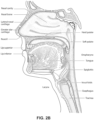
- the respiratory system of the body facilitates gas exchange.
- the nose and mouth form the entrance to the airways of a patient.
- the airways include a series of branching tubes, which become narrower, shorter and more numerous as they penetrate deeper into the lung.
- the prime function of the lung is gas exchange, allowing oxygen to move from the inhaled air into the venous blood and carbon dioxide to move in the opposite direction.
- the trachea divides into right and left main bronchi, which further divide eventually into terminal bronchioles.
- the bronchi make up the conducting airways, and do not take part in gas exchange. Further divisions of the airways lead to the respiratory bronchioles, and eventually to the alveoli.
- the alveolated region of the lung is where the gas exchange takes place, and is referred to as the respiratory zone. See " Respiratory Physiology", by John B. West, Lippincott Williams & Wilkins, 9th edition published 2012 .
- a range of respiratory disorders exist. Certain disorders may be characterised by particular events, e.g. apneas, hypopneas, and hyperpneas.
- respiratory disorders include Obstructive Sleep Apnea (OSA), Cheyne-Stokes Respiration (CSR), respiratory insufficiency, Obesity Hyperventilation Syndrome (OHS), Chronic Obstructive Pulmonary Disease (COPD), Neuromuscular Disease (NMD) and Chest wall disorders.
- OSA Obstructive Sleep Apnea
- CSR Cheyne-Stokes Respiration
- OOS Obesity Hyperventilation Syndrome
- COPD Chronic Obstructive Pulmonary Disease
- NMD Neuromuscular Disease
- Chest wall disorders examples include Obstructive Sleep Apnea (OSA), Cheyne-Stokes Respiration (CSR), respiratory insufficiency, Obesity Hyperventilation Syndrome (OHS), Chronic Obstructive Pulmonary Disease (COPD), Neuromuscular Disease (NMD) and Chest wall disorders.
- Obstructive Sleep Apnea a form of Sleep Disordered Breathing (SDB), is characterised by events including occlusion or obstruction of the upper air passage during sleep. It results from a combination of an abnormally small upper airway and the normal loss of muscle tone in the region of the tongue, soft palate and posterior oropharyngeal wall during sleep.
- the condition causes the affected patient to stop breathing for periods typically of 30 to 120 seconds in duration, sometimes 200 to 300 times per night. It often causes excessive daytime somnolence, and it may cause cardiovascular disease and brain damage.
- the syndrome is a common disorder, particularly in middle aged overweight males, although a person affected may have no awareness of the problem. See US Patent No. 4,944,310 (Sullivan ).
- CSR Cheyne-Stokes Respiration
- CSR cycles rhythmic alternating periods of waxing and waning ventilation known as CSR cycles.
- CSR is characterised by repetitive de-oxygenation and re-oxygenation of the arterial blood. It is possible that CSR is harmful because of the repetitive hypoxia. In some patients CSR is associated with repetitive arousal from sleep, which causes severe sleep disruption, increased sympathetic activity, and increased afterload. See US Patent No. 6,532,959 (Berthon-Jones ).
- Respiratory failure is an umbrella term for respiratory disorders in which the lungs are unable to inspire sufficient oxygen or exhale sufficient CO 2 to meet the patient's needs. Respiratory failure may encompass some or all of the following disorders.
- a patient with respiratory insufficiency (a form of respiratory failure) may experience abnormal shortness of breath on exercise.
- ALS Amyotrophic lateral sclerosis
- DMD Duchenne muscular dystrophy
- Variable or slowly progressive disorders Characterised by muscle impairment that worsens over years and only mildly reduces life expectancy (e.g. Limb girdle, Facioscapulohumeral and Myotonic muscular dystrophy).
- Symptoms of respiratory failure in NMD include: increasing generalised weakness, dysphagia, dyspnea on exertion and at rest, fatigue, sleepiness, morning headache, and difficulties with concentration and mood changes.
- Chest wall disorders are a group of thoracic deformities that result in inefficient coupling between the respiratory muscles and the thoracic cage.
- the disorders are usually characterised by a restrictive defect and share the potential of long term hypercapnic respiratory failure.
- Scoliosis and/or kyphoscoliosis may cause severe respiratory failure.
- Symptoms of respiratory failure include: dyspnea on exertion, peripheral oedema, orthopnea, repeated chest infections, morning headaches, fatigue, poor sleep quality and loss of appetite.
- Continuous Positive Airway Pressure (CPAP) therapy has been used to treat Obstructive Sleep Apnea (OSA).
- OSA Obstructive Sleep Apnea
- the mechanism of action is that continuous positive airway pressure acts as a pneumatic splint and may prevent upper airway occlusion, such as by pushing the soft palate and tongue forward and away from the posterior oropharyngeal wall.
- Treatment of OSA by CPAP therapy may be voluntary, and hence patients may elect not to comply with therapy if they find devices used to provide such therapy one or more of: uncomfortable, difficult to use, expensive and aesthetically unappealing.
- Non-invasive ventilation provides ventilatory support to a patient through the upper airways to assist the patient breathing and/or maintain adequate oxygen levels in the body by doing some or all of the work of breathing.
- the ventilatory support is provided via a non-invasive patient interface.
- NIV has been used to treat CSR and respiratory failure, in forms such as OHS, COPD, NMD and Chest Wall disorders. In some forms, the comfort and effectiveness of these therapies may be improved.
- IV Invasive ventilation
- These therapies may be provided by a treatment system or device. Such systems and devices may also be used to screen, diagnose, or monitor a condition without treating it.
- a treatment system may comprise a Respiratory Pressure Therapy Device (RPT device), an air circuit, a humidifier, a patient interface, and data management.
- RPT device Respiratory Pressure Therapy Device
- Another form of treatment system is a mandibular repositioning device.
- a patient interface may be used to interface respiratory equipment to its wearer, for example by providing a flow of air to an entrance to the airways.
- the flow of air may be provided via a mask to the nose and/or mouth, a tube to the mouth or a tracheostomy tube to the trachea of a patient.
- the patient interface may form a seal, e.g., with a region of the patient's face, to facilitate the delivery of gas at a pressure at sufficient variance with ambient pressure to effect therapy, e.g., at a positive pressure of about 10 cmH 2 O relative to ambient pressure.
- the patient interface may not include a seal sufficient to facilitate delivery to the airways of a supply of gas at a positive pressure of about 10 cmH 2 O.
- Certain other mask systems may be functionally unsuitable for the present field.
- purely ornamental masks may be unable to maintain a suitable pressure.
- Mask systems used for underwater swimming or diving may be configured to guard against ingress of water from an external higher pressure, but not to maintain air internally at a higher pressure than ambient.
- Certain masks may be clinically unfavourable for the present technology e.g. if they block airflow via the nose and only allow it via the mouth.
- Certain masks may be uncomfortable or impractical for the present technology if they require a patient to insert a portion of a mask structure in their mouth to create and maintain a seal via their lips.
- Certain masks may be impractical for use while sleeping, e.g. for sleeping while lying on one's side in bed with a head on a pillow.
- the design of a patient interface presents a number of challenges.
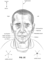
- the face has a complex three-dimensional shape.
- the size and shape of noses and heads varies considerably between individuals. Since the head includes bone, cartilage and soft tissue, different regions of the face respond differently to mechanical forces.
- the jaw or mandible may move relative to other bones of the skull. The whole head may move during the course of a period of respiratory therapy.
- masks suffer from being one or more of obtrusive, aesthetically undesirable, costly, poorly fitting, difficult to use, and uncomfortable especially when worn for long periods of time or when a patient is unfamiliar with a system. Wrongly sized masks can give rise to reduced compliance, reduced comfort and poorer patient outcomes.
- Masks designed solely for aviators, masks designed as part of personal protection equipment (e.g. filter masks), SCUBA masks, or for the administration of anaesthetics may be tolerable for their original application, but nevertheless such masks may be undesirably uncomfortable to be worn for extended periods of time, e.g., several hours. This discomfort may lead to a reduction in patient compliance with therapy. This is even more so if the mask is to be worn during sleep.
- CPAP therapy is highly effective to treat certain respiratory disorders, provided patients comply with therapy. If a mask is uncomfortable, or difficult to use a patient may not comply with therapy. Since it is often recommended that a patient regularly wash their mask, if a mask is difficult to clean (e.g., difficult to assemble or disassemble), patients may not clean their mask and this may impact on patient compliance.
- a mask for other applications may not be suitable for use in treating sleep disordered breathing
- a mask designed for use in treating sleep disordered breathing may be suitable for other applications.
- patient interfaces for delivery of CPAP during sleep form a distinct field.
- Patient interfaces may include a seal-forming structure. Since it is in direct contact with the patient's face, the shape and configuration of the seal-forming structure can have a direct impact the effectiveness and comfort of the patient interface.
- a patient interface may be partly characterised according to the design intent of where the seal-forming structure is to engage with the face in use.
- a seal-forming structure may comprise a first sub-portion to form a seal around the left naris and a second sub-portion to form a seal around the right naris.
- a seal-forming structure may comprise a single element that surrounds both nares in use. Such single element may be designed to for example overlay an upper lip region and a nasal bridge region of a face.
- a seal-forming structure may comprise an element that surrounds a mouth region in use, e.g. by forming a seal on a lower lip region of a face.
- a seal-forming structure may comprise a single element that surrounds both nares and a mouth region in use.
- These different types of patient interfaces may be known by a variety of names by their manufacturer including nasal masks, full-face masks, nasal pillows, nasal puffs and oro-nasal masks.
- a seal-forming structure that may be effective in one region of a patient's face may be inappropriate in another region, e.g. because of the different shape, structure, variability and sensitivity regions of the patient's face.
- a seal on swimming goggles that overlays a patient's forehead may not be appropriate to use on a patient's nose.
- Certain seal-forming structures may be designed for mass manufacture such that one design fit and be comfortable and effective for a wide range of different face shapes and sizes. To the extent to which there is a mismatch between the shape of the patient's face, and the seal-forming structure of the mass-manufactured patient interface, one or both must adapt in order for a seal to form.
- seal-forming structure extends around the periphery of the patient interface, and is intended to seal against the patient's face when force is applied to the patient interface with the seal-forming structure in confronting engagement with the patient's face.
- the seal-forming structure may include an air or fluid filled cushion, or a moulded or formed surface of a resilient seal element made of an elastomer such as a rubber.
- seal-forming structure incorporates a flap seal of thin material positioned about the periphery of the mask so as to provide a self-sealing action against the face of the patient when positive pressure is applied within the mask.
- flap seal of thin material positioned about the periphery of the mask so as to provide a self-sealing action against the face of the patient when positive pressure is applied within the mask.
- additional force may be required to achieve a seal, or the mask may leak.
- shape of the seal-forming structure does not match that of the patient, it may crease or buckle in use, giving rise to leaks.
- seal-forming structure may comprise a friction-fit element, e.g. for insertion into a naris, however some patients find these uncomfortable.
- seal-forming structure may use adhesive to achieve a seal. Some patients may find it inconvenient to constantly apply and remove an adhesive to their face.
- nasal pillow is found in the Adam Circuit manufactured by Puritan Bennett.
- Another nasal pillow, or nasal puff is the subject of US Patent 4,782,832 (Trimble et al.), assigned to Puritan-Bennett Corporation .
- RPT device used for treating sleep disordered breathing is the S9 Sleep Therapy System, manufactured by ResMed Limited.
- RPT device is a ventilator.
- Ventilators such as the ResMed Stellar TM Series of Adult and Paediatric Ventilators may provide support for invasive and non-invasive non-dependent ventilation for a range of patients for treating a number of conditions such as but not limited to NMD, OHS and COPD.
- the ResMed Elo TM 150 ventilator and ResMed VS III TM ventilator may provide support for invasive and non-invasive dependent ventilation suitable for adult or paediatric patients for treating a number of conditions. These ventilators provide volumetric and barometric ventilation modes with a single or double limb circuit.
- RPT devices typically comprise a pressure generator, such as a motor-driven blower or a compressed gas reservoir, and are configured to supply a flow of air to the airway of a patient. In some cases, the flow of air may be supplied to the airway of the patient at positive pressure.
- the outlet of the RPT device is connected via an air circuit to a patient interface such as those described above.
- the designer of a device may be presented with an infinite number of choices to make. Design criteria often conflict, meaning that certain design choices are far from routine or inevitable. Furthermore, the comfort and efficacy of certain aspects may be highly sensitive to small, subtle changes in one or more parameters.
- a range of artificial humidification devices and systems are known, however they may not fulfil the specialised requirements of a medical humidifier.
- Medical humidifiers are used to increase humidity and/or temperature of the flow of air in relation to ambient air when required, typically where the patient may be asleep or resting (e.g. at a hospital).
- a medical humidifier for bedside placement may be small.
- a medical humidifier may be configured to only humidify and/or heat the flow of air delivered to the patient without humidifying and/or heating the patient's surroundings.
- Room-based systems e.g. a sauna, an air conditioner, or an evaporative cooler
- medical humidifiers may have more stringent safety constraints than industrial humidifiers
- a compliance rule for CPAP therapy is that a patient, in order to be deemed compliant, is required to use the RPT device for at least four hours a night for at least 21 of 30 consecutive days.
- a provider of the RPT device such as a health care provider, may manually obtain data describing the patient's therapy using the RPT device, calculate the usage over a predetermined time period, and compare with the compliance rule. Once the health care provider has determined that the patient has used their RPT device according to the compliance rule, the health care provider may notify a third party that the patient is compliant.
- a mandibular repositioning device (MRD) or mandibular advancement device (MAD) is one of the treatment options for sleep apnea and snoring. It is an adjustable oral appliance available from a dentist or other supplier that holds the lower jaw (mandible) in a forward position during sleep.
- the MRD is a removable device that a patient inserts into their mouth prior to going to sleep and removes following sleep. Thus, the MRD is not designed to be worn all of the time.
- the MRD may be custom made or produced in a standard form and includes a bite impression portion designed to allow fitting to a patient's teeth. This mechanical protrusion of the lower jaw expands the space behind the tongue, puts tension on the pharyngeal walls to reduce collapse of the airway and diminishes palate vibration.
- a mandibular advancement device may comprise an upper splint that is intended to engage with or fit over teeth on the upper jaw or maxilla and a lower splint that is intended to engage with or fit over teeth on the upper jaw or mandible.
- the upper and lower splints are connected together laterally via a pair of connecting rods.
- the pair of connecting rods are fixed symmetrically on the upper splint and on the lower splint.
- the length of the connecting rods is selected such that when the MRD is placed in a patient's mouth the mandible is held in an advanced position.
- the length of the connecting rods may be adjusted to change the level of protrusion of the mandible.
- a dentist may determine a level of protrusion for the mandible that will determine the length of the connecting rods.
- MRDs are structured to push the mandible forward relative to the maxilla while other MADs, such as the ResMed Narval CC TM MRD are designed to retain the mandible in a forward position.
- This device also reduces or minimises dental and temporo-mandibular joint (TMJ) side effects. Thus, it is configured to minimises or prevent any movement of one or more of the teeth.
- Some forms of treatment systems may include a vent to allow the washout of exhaled carbon dioxide.
- the vent may allow a flow of gas from an interior space of a patient interface, e.g., the plenum chamber, to an exterior of the patient interface, e.g., to ambient.
- the vent may comprise an orifice and gas may flow through the orifice in use of the mask. Many such vents are noisy. Others may become blocked in use and thus provide insufficient washout. Some vents may be disruptive of the sleep of a bed partner 1100 of the patient 1000, e.g. through noise or focussed airflow.
- ResMed Limited has developed a number of improved mask vent technologies. See International Patent Application Publication No. WO 1998/034665 ; International Patent Application Publication No. WO 2000/078381 ; US Patent No. 6,581,594 ; US Patent Application Publication No. US 2009/0050156 ; US Patent Application Publication No. 2009/0044808 .
- PSG Polysomnography
- EEG electroencephalography
- ECG electrocardiography
- EOG electrooculograpy
- EMG electromyography
- PSG for sleep disordered breathing has involved two nights of observation of a patient in a clinic, one night of pure diagnosis and a second night of titration of treatment parameters by a clinician.
- PSG is therefore expensive and inconvenient. In particular it is unsuitable for home screening / diagnosis / monitoring of sleep disordered breathing.
- Screening and diagnosis generally describe the identification of a condition from its signs and symptoms. Screening typically gives a true / false result indicating whether or not a patient's SDB is severe enough to warrant further investigation, while diagnosis may result in clinically actionable information. Screening and diagnosis tend to be one-off processes, whereas monitoring the progress of a condition can continue indefinitely. Some screening / diagnosis systems are suitable only for screening / diagnosis, whereas some may also be used for monitoring.
- WO 2012/154883 A2 discusses a method for adjusting a ventilation mask, a ventilation mask seal, a nasal passage opener, a carbon dioxide sampling device, configuration for use of a reusable insert, a lateral gas line, a non-invasive tube insertion region and exhaust port, a protective facial interface, and quick donning headgear.
- WO 2004/073778 Al relates to a nasal assembly for delivering breathable gas to a patient including a frame having an integrally formed first connector portion. It is said that at least one inlet conduit is structured to deliver breathable gas into the frame and nozzle assembly for breathing by the patient. Furthermore, it is said that a pair of second connector portions are removably and rotatably connected to respective first connector portions of the frame and are in communication with respective inlet conduits, e.g., directly or via angle connectors. Moreover, it is said that headgear assembly is removably connected to the pair of second connector portions and/or the angle connectors so as to maintain the frame and the nozzle assembly in a desired adjusted position on the patient's face.
- An aspect of the present technology is directed to a patient interface that includes: a plenum chamber at least partly forming a patient interface chamber that is pressurisable to a therapeutic pressure of at least 6 cmH 2 O above ambient air pressure, a seal-forming structure constructed and arranged to form a seal with a region of the patient's face surrounding an entrance to the patient's airways, a first conduit and a second conduit each being sized and structured to receive the flow of air at the therapeutic pressure for breathing by the patient, a first conduit connector configured to pneumatically connect the first conduit to the plenum chamber to provide the flow of air at the therapeutic pressure to the patient interface chamber for breathing by the patient and a second conduit connector configured to pneumatically connect the second conduit to the plenum chamber to provide the flow of air at the therapeutic pressure to the patient interface chamber for breathing by the patient, a positioning and stabilising structure to provide a force to hold the seal-forming structure in a therapeutically effective position on the patient's head, the positioning and stabilising structure comprising at least one tie, and at least
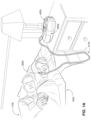
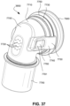
- the clip member 7730 includes a pair of resilient, quick release pinch arms 7740 and a connecting portion 7760 that interconnects the pinch arms 7740, i.e., pinch arm 7740 provided at each end of the connecting portion 7760.
- the two-part construction may allow each part to be less complex in geometry, resulting in an assembly that may allow simpler tooling for manufacture.
- the clip member 7730 may not be removably connected to the elbow member 7710, e.g., clip member may be permanently connected to the elbow member.
- Such non-removable arrangement may be advantageous as it reduces the possibly of the clip member being lost or broken. Since the clip member is outside of the air flow path, a thorough cleaning may not be as essential, e.g., compared to components exposed to the air flow path.
- decoupling is provided by the pinch arms 7740 which form the swivel connection allowing 360° free rotation of the elbow assembly 7700 relative to the ring member 7900.
- Another form of decoupling is provided by the swivel connector 7790 allowing 360° free rotation of the swivel connector 7790 (and the air circuit 4170 connection thereto) relative to the elbow member 7710.
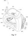
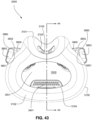
- the patient interface 3000 includes a forehead support 3700.
- Examples of the patient interface of the present technology shown in Figs. 7-36 do not include a forehead support. Variations of the patient interface of the present technology may include a forehead support.
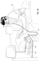
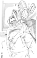
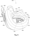
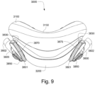
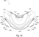
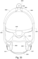
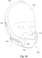
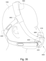
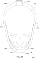
- the patient interface 3000 may include conduits 3900 to provide the flow of pressurized from the connection port 3600 to the patient interface chamber 3001.
- the conduits 3900 may be joined superior to the patient's head at the connection port housing 3903 and may pass along lateral sides of the patient's head between corresponding ones of the patient's eyes and ears.
- the conduits 3900 may be connected to the plenum chamber 3200 via conduit connectors 3800, as described below, to provide the flow of pressurized air to the patient interface chamber 3001.
- the conduits 3900 may also provide stabilize and position the seal-forming structure 3100 on the patient's face.
- the conduits 3900 may function similarly to the ties of the positioning and stabilising structure 3300. Accordingly, the mechanical connection of the conduits 3900 to the conduit connectors 3800 may be sufficient for tension forces in the conduits 3900 to be transmitted to the seal-forming structure 3100 through the conduit connectors 3800.
- the conduits 3900 may include features of similar conduits disclosed in International Application Publication No. WO 2017/124155 A1 .
- conduits 3900 of the present technology may include features of the headgear tubes 3350 depicted in FIGS. 3A-3L of this document, as well as the associated written description.
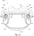
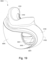
- the conduits 3900 may also be provided with sleeves 3901 to cushion the patient's face against the conduits 3900.
- the sleeves 3901 may be removable.
- the sleeves 3901 may be made from a breathable material.
- connection between the conduit connectors 3800 and the plenum chamber 3200 may also be designed to be sufficiently strong such that tension from the conduits 3900 can be transferred to the plenum chamber 3200 without disrupting the connection because, as explained above, the conduit connectors 3800 may facilitate positioning and stabilising of the seal-forming structure 3100 on the patient's head.
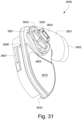
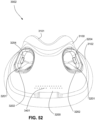
- the conduit connectors 3800 may also be attached to lateral sides of the plenum chamber 3200 to improve aesthetics of the patient interface 3000.
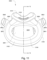
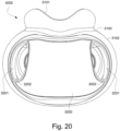
- the plenum chamber 3200 may be constructed of a transparent or translucent material, which may allow visibility of the patient's facial features.
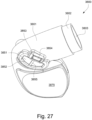
- the conduit connectors 3800 and the plenum chamber holes 3201 may also be arranged so that at least a portion of the conduit connector housing 3801 extends into the patient interface chamber 3001. This arrangement may reduce the dead space within the patient interface chamber 3001 by making use of volume within the patient interface chamber 3001 with the conduit connectors 3800. Accordingly, less of the conduit connectors 3800 overall volume extends outwardly from the patient interface 3000. This may be advantageous because it reduces the excess structures that are susceptible to being caught on bedding, and it provide a sleeker aesthetic for the patient that may be more visually appealing.
- the conduit connectors 3800 may also each include a conduit connection end 3802 that connects to a respective conduit 3900.
- the connection between the conduits 3900 and the conduit connectors 3800 at the conduit connection ends 3802 may be removable or permanent.
- a conduit connector inlet hole 3803 may be formed in the conduit connector housing 3801 at the conduit connection end 3802 to receive the flow of pressurized air.
- the conduit connectors 3800 may include structure, e.g., an undercut, to facilitate a removable, snap-fit connection with corresponding conduits 3900, and each conduit 3900 may include a relatively rigid structure at the end that connects to the conduit connectors 3800 to facilitate such a connection.
- the conduit connectors 3800 may also be joined to the conduits 3900 with a friction fit.
- the conduits 3900 may provide a positioning and stabilising function to locate the seal-forming structure in a therapeutically effective sealing position on the patient's face, and therefore the connection between the conduits 3900 and the conduit connectors 3800 at the conduit connection ends 3802 may be sufficiently secure to permit tension forces from the conduits 3900 to be transmitted to the conduit connectors 3800 without disrupting the connection between the conduits 3900 and the conduit connectors 3800 at the conduit connection ends 3802.
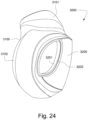
- the conduit connectors 3800 may also provide a venting function for the patient interface 3000.
- the conduit connector housing 3801 may include a conduit connector vent inlet 3832 that is in pneumatic communication with the patient interface chamber 3001 when the patient interface 3000 is assembled.
- the conduit connector housing 3801 may also include at least one conduit connector vent hole 3831.
- each conduit connector housing 3801 includes a plurality of conduit connector vent holes 3831.
- the conduit connector housing 3801 may also include a baffle 3805 to prevent air entering the patient interface chamber 3001 via the conduit connector outlet hole 3804 from escaping directly out the conduit connector vent hole(s) 3831.
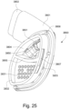
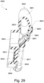
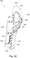
- the conduit connector housing 3801 may also include at least one conduit connector vent spacer 3833 - FIGS. 25-31 show a plurality of conduit connector vent spacers 3833 in these examples - to provide a passageway for exhaled gas to escape to atmosphere from the conduit connectors 3800 via a conduit connector vent outlet 3830.
- the conduit connector vent spacers 3833 may be distributed around a portion of the perimeter of the conduit connector housing 3801.
- the conduit connector vent spacers 3833 may maintain spacing between a portion of the conduit connector housing 3801 and the plenum chamber 3200 for the conduit connector vent outlet 3830.
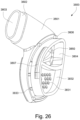
- the conduit connector housing 3801 may also include a diffuser cavity 3871 that may contain diffuser material (not shown).
- the diffuser material may be enclosed within the diffuser cavity 3871 by a diffuser cover 3870.
- the diffuser cover 3870 may be permanently attached to the conduit connector housing 3801, which prevents the patient from changing the diffuser material if it becomes occluded due to contaminants.
- the diffuser cover 3870 may be ultrasonically welded to the conduit connector housing 3801.
- the diffuser cover 3870 may be removably attached to the conduit connector housing 3801, e.g., via a snap-fit or a friction fit, which would permit the patient to replace the diffuser material.
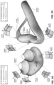
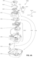
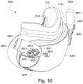
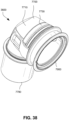
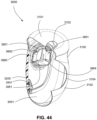
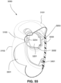
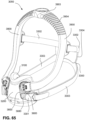
- FIGS. 39-66 depict another example of the present technology that includes features similar to the example depicted in FIGS. 7-36 .
- the example in FIGS. 39-66 also includes features that are different from the example depicted in FIGS. 7-36 .
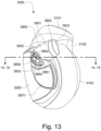
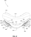
- the plenum chamber 3200 includes a plurality of plenum chamber vent holes 3401 to permit the discharge of gas, including exhaled carbon dioxide, from the patient interface chamber 3001 to atmosphere.
- the conduit connectors 3800 of this example do not include any venting structures (i.e. , conduit connector vent outlet 3830, conduit connector vent hole 3831, conduit connector vent inlet 3832, etc.) present in the preceding example because the plenum chamber vent holes 3401 can be sized, shaped, and a large enough number provided to permit sufficient carbon dioxide washout.
- the conduit connectors 3800 may include the conduit connector vent outlet 3830, conduit connector vent hole 3831, conduit connector vent inlet 3832, etc., while the plurality of plenum chamber vent holes 3401 are also provided on the plenum chamber 3200. This arrangement may be advantageous in that it may provide additional and/or more diffuse venting.
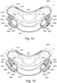
- conduit connectors 3800 of this example do not include any venting structures (i.e. , conduit connector vent outlet 3830, the anti-asphyxia valve assembly 3850 is still provided to each of the conduit connectors 3800 for safety reasons.
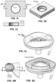
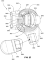
- FIGS. 46 and 47 show movement of the anti-asphyxia valve flap 3851 between open and closed positions, similar to the example described above.
- the plenum chamber 3200 may have no sealing structure on the plenum chamber holes 3201.
- sealing between the conduit connectors 3800 and the plenum chamber 3200 may be accomplished with conduit connector outlet seal 3861 joined around the exterior perimeter of the conduit connector outlet 3808.
- the conduit connector outlet seal 3861 may be constructed of an elastomeric material, e.g., silicone, that deforms upon contact with a connection rim 3202 around each plenum chamber hole 3201.
- the conduit connector outlet seal 3861 may be overmolded to the conduit connector outlet 3808.
- the conduit connector outlet seals 3861 deform against the connection rim 3202 and ensure sealing therebetween.
- the conduit connector outlet seal 3861 in this example may extend around the entirety of the conduit connector outlet 3808or the conduit connector outlet seal 3861 may only be provided at one or more selected portions around the conduit connector outlet 3808.
- conduit connector outlet seal 3861 is provided to the connection rim 3202 of each plenum chamber hole 3201 to be deformed against the conduit connector outlet 3808 of each conduit connector 3800.
- the conduit connector outlet seal 3861 in this example may extend around the entirety of the plenum chamber hole 3201 or the conduit connector outlet seal 3861 may only be provided at one or more selected portions around the plenum chamber hole 3201.
- conduit connector 3800 there may be no deformable sealing component between the conduit connector 3800 and the connection rim 3202 of the corresponding plenum chamber hole 3201.
- leak may be permitted in this alternative or the tolerances between the conduit connector 3800 and the connection rim 3202 of the corresponding plenum chamber hole 3201 may be so small as to permit little or no leak.
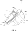
- the conduit connectors 3800 may be configured to provide a releasable connection to the plenum chamber 3200 at the corresponding plenum chamber hole 3201.
- the conduit connectors 3800 may be constructed of a relatively rigid, plastic material, e.g., polycarbonate, to facilitate the connection described below.
- a slot 3203 and a detent 3204 may be formed on the plenum chamber 3200 at each plenum chamber hole 3201 to engage with corresponding structures of the conduit connectors 3800.
- the engagement process may begin by engaging a first tab 3890 with the slot 3203 from an anterior side ( i.e. , facing away from the patient in use) of the plenum chamber 3200.
- the first tab 3890 may be relatively rigid and its engagement with the slot 3203 may act as a fulcrum so that the conduit connector 3800 can then be rotated about the slot 3203 to complete the engagement process.
- the engagement process may be completed by a second tab 3891 having a catch 3892 engaging the detent 3204 of the plenum chamber 3204.
- the conduit connector outlet seal 3861 may engage the corresponding connection rim 3202 to establish a pneumatic seal. Additionally, the conduit connector outlet 3808 may extend, at least partially, through the corresponding plenum chamber hole 3201 so that gas can travel between the patient interface chamber 3001 and the conduit connector 3800.
- the second tab 3891 may be flexible so that when the catch 3892 and the detent 3204 come into engagement a snap-fit connection is established. This may be beneficial for the patient because the snap-fit connection provides tactile and audible feedback that the connection is established. Gaps 3893 on either side of the second tab 3891 and between the conduit connector outlet 3808 allow the second tab 3891 to be cantilevered for easier deformation during the engagement and disengagement processes.
- the disengagement process happens in the opposite order by first disengaging the catch 3892 from the corresponding detent 3204 by rotating the conduit connector 3800 in an anterior direction away from the plenum chamber 3200. Since the second tab 3891 is flexible, once sufficient force is applied the second tab will deflect and allow the catch 3892 to disengage from the detent 3204. The conduit connector 3800 is then rotated further so that the first tab 3890 disengages from the slot 3203. During the disengagement process, the conduit connector outlet seal 3861 also disengages from the corresponding connection rim 3202 and the conduit connector outlet 3808 exits the corresponding plenum chamber hole 3201.
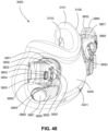
- the conduit connector 3800 When engaged, the conduit connector 3800 may protrude in an anterior direction relative to the plenum chamber 3200 such that the conduits 3900 are directed laterally away from the plenum chamber 3200.
- the conduits 3900 By locating the conduits 3900 forward of the plenum chamber 3200, the conduits 3900 may remain engaged and undamaged when lateral forces pull the conduits 3900 away from the plenum chamber 3200, while also lowering the force required to disengage the conduit connectors 3800, and therefore also the conduits 3900, from the plenum chamber 3200.
- conduits 3900 may be joined to the conduit connectors 3800 with sufficient strength to resist disengagement in a lateral direction, while also allowing the conduit connectors 3800 to be relatively easily removed from the plenum chamber 3200 by rotating out of the plenum chamber holes 3201, as described above.
- This arrangement may be beneficial in the typical use case because lateral forces may be common during use, i.e. , sleep, and it is advantageous to ensure that the patient interface 3000 can resist these forces without disrupting the connection between the conduits 3900 and the plenum chamber 3200, and therefore the flow of gas.
- forces that would cause the disengagement process described above to occur are less common during sleep.
- first tab 3890 and the second tab 3891 can be designed to engage and disengage from the slot 3203 and detent 3204 with relatively low force in the respective directions, which in turn allows the patient to easily engage and disengage the conduit connectors 3800.
- the disengagement force in this example may be as low as 8 to 12 Newtons.
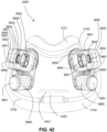
- the force required to disengage the conduit connectors 3800 may be sufficiently low that the conduit connectors 3800 may be disengaged by application of a force in an anterior direction on a flange 3885 configured for magnetic fastening of positioning and stabilising structure 3300.
- the conduit connector 3800 may also include a flange 3885 to connect the inferior ties 3303 to the conduit connector 3800 via clips 3301.
- the flange 3885 may extend from the conduit connector 3800.
- the flange 3885 may be molded in one piece with the conduit connector 3800.
- the flange 3885 may include a flange opening 3887 and a recess 3886 to receive a tab connector 3884 of an inferior tie tab 3880.
- the tab connector 3884 passes through the flange opening 3887 and engages in the recess 3886.
- the inferior tie tab 3880 may include a clip receiver 3881 that may house a magnet to provide a releasable connection to a corresponding magnet in a clip 3301.
- the clip receiver 3881 may also engage with an overhang 3307 of the clip 3301 to ensure that the clip 3301 remains engaged with the inferior tie tab 3880.
- attraction between the magnets of the clip 3301 and the clip receiver 3881 may provide a locating function while engagement of the overhang 3307 and the clip receiver 3881 ensure that the clip 3301 remains securely connected to the inferior tie tab 3880.
- connection between the clip 3301 and the inferior tie tab 3880 is releasable by applying force sufficient to overcome the attraction between the two magnets.
- the inferior tie tab 3880 may also include a notch 3882.
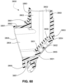
- the conduit 3900 may be joined to the conduit connector 3800 at the conduit connector end 3802 permanently or removably.
- FIG. 63 depicts an example of a permanent connection whereby an intermediate conduit connector inlet seal 3860, e.g., of silicone, is molded around the conduit connector end 3802.
- the conduit 3900 which may also be silicone, is molded onto the intermediate conduit connector inlet seal 3860.
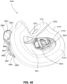
- the patient interface 3000 includes an anti-asphyxia valve.
- each of the conduit connectors 3800 may include an anti-asphyxia valve assembly 3850.
- the patient interface 3000 may include two anti-asphyxia valve assemblies 3850.
- Each of the anti-asphyxia valve assemblies 3850 may operate independent of the other, i.e. , in response to a cessation of the flow of pressurized air.
- the other of the anti-asphyxia valve assemblies 3850 can function to prevent the patient from being asphyxiated.
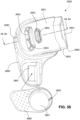
- the anti-asphyxia valve assembly 3850 may include an anti-asphyxia valve flap 3851 that covers an anti-asphyxia valve hole 3852 in a closed position.
- the anti-asphyxia valve flap 3851 may be configured to remain in the closed position during the patient's entire respiratory cycle, i.e. , inhalation and exhalation.
- FIGS. 15 and 30 depict the anti-asphyxia valve flap 3851 in an open position in which the anti-asphyxia valve hole 3852 is not covered such that the patient can breathe from atmosphere via the anti-asphyxia valve hole 3852, if there is a cessation of the flow of pressurized air.
- the anti-asphyxia valve flap 3851 may be constructed such that the open position may be the default, neutral, or undeformed position so that only when the pressurized flow of air, at least to a minimum flow rate and/or pressure, is applied is the anti-asphyxia valve flap 3851 moved to the closed position by the force of the pressure and/or flow of the air. Additionally, the anti-asphyxia valve hole 3852 may be sized sufficiently so that if one of the anti-asphyxia valve assemblies 3850 is occluded and prevented from permitting respiration, the patient can breathe adequately through the non-occluded anti-asphyxia valve assembly 3850.
- the anti-asphyxia valve flap 3851 may be sized so as to completely occlude the anti-asphyxia valve hole 3852 in the closed position.
- the anti-asphyxia valve flap 3851 may include holes that allow air to pass through to atmosphere, e.g., for venting, in the closed position.
- the anti-asphyxia valve flap 3851 may be joined to the conduit connector housing 3801 with an anti-asphyxia valve flap connector 3854 that extends into an anti-asphyxia valve flap connector hole 3853.
- the anti-asphyxia valve flap 3851 may be permanently attached to the conduit connector housing 3801 at the anti-asphyxia valve flap connector hole 3853 by being overmoulded onto the conduit connector housing 3801.
- the anti-asphyxia valve flap 3851 may be made of a flexible, elastic material that allows it to be deflected from the open position to the closed position by the force of the pressure and/or flow of the air.
- the an anti-asphyxia valve assembly 3850 may also include an anti-asphyxia valve hole divider 3855 across the anti-asphyxia valve hole 3852.
- the anti-asphyxia valve hole divider 3855 may prevent the anti-asphyxia valve flap 3851 from being pushed out the anti-asphyxia valve hole 3852 due to pressure within the patient interface chamber 3001.
- a patient interface 3000 includes one or more ports that allow access to the volume within the plenum chamber 3200. In one form this allows a clinician to supply supplemental oxygen. In one form, this allows for the direct measurement of a property of gases within the plenum chamber 3200, such as the pressure.
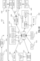
- An RPT device 4000 in accordance with one aspect of the present technology comprises mechanical, pneumatic, and/or electrical components and is configured to execute one or more algorithms, such as any of the methods, in whole or in part, described herein.
- the RPT device 4000 may be configured to generate a flow of air for delivery to a patient's airways, such as to treat one or more of the respiratory conditions described elsewhere in the present document.
- a signal from the pressure sensor 4272 is received by the central controller 4230.
- a motor speed transducer 4276 is used to determine a rotational velocity of the motor 4144 and/or the blower 4142.
- a motor speed signal from the motor speed transducer 4276 may be provided to the therapy device controller 4240.
- the motor speed transducer 4276 may, for example, be a speed sensor, such as a Hall effect sensor.
- power supply 4210 provides electrical power to the RPT device 4000 only. In another form of the present technology, power supply 4210 provides electrical power to both RPT device 4000 and humidifier 5000.
- an RPT device 4000 includes one or more input devices 4220 in the form of buttons, switches or dials to allow a person to interact with the device.
- the buttons, switches or dials may be physical devices, or software devices accessible via a touch screen.
- the buttons, switches or dials may, in one form, be physically connected to the external housing 4010, or may, in another form, be in wireless communication with a receiver that is in electrical connection to the central controller 4230.
- the input device 4220 may be constructed and arranged to allow a person to select a value and/or a menu option.
- the central controller 4230 is one or a plurality of processors suitable to control an RPT device 4000.
- Suitable processors may include an x86 INTEL processor, a processor based on ARM ® Cortex ® -M processor from ARM Holdings such as an STM32 series microcontroller from ST MICROELECTRONIC.
- a 32-bit RISC CPU such as an STR9 series microcontroller from ST MICROELECTRONICS or a 16-bit RISC CPU such as a processor from the MSP430 family of microcontrollers, manufactured by TEXAS INSTRUMENTS may also be suitable.
- the central controller 4230 is a dedicated electronic circuit.
- the central controller 4230 is an application-specific integrated circuit. In another form, the central controller 4230 comprises discrete electronic components.
- the central controller 4230 may be configured to receive input signal(s) from one or more transducers 4270, one or more input devices 4220, and the humidifier 5000.
- the central controller 4230 may be configured to provide output signal(s) to one or more of an output device 4290, a therapy device controller 4240, a data communication interface 4280, and the humidifier 5000.
- the central controller 4230 is configured to implement the one or more methodologies described herein, such as the one or more algorithms expressed as computer programs stored in a non-transitory computer readable storage medium, such as memory 4260.
- the central controller 4230 may be integrated with an RPT device 4000.
- some methodologies may be performed by a remotely located device.
- the remotely located device may determine control settings for a ventilator or detect respiratory related events by analysis of stored data such as from any of the sensors described herein.
- the RPT device 4000 may include a clock 4232 that is connected to the central controller 4230.
- therapy device controller 4240 is a therapy control module that forms part of the algorithms executed by the central controller 4230.
- therapy device controller 4240 is a dedicated motor control integrated circuit.
- a MC33035 brushless DC motor controller manufactured by ONSEMI is used.
- the one or more protection circuits 4250 in accordance with the present technology may comprise an electrical protection circuit, a temperature and/or pressure safety circuit.
- the RPT device 4000 includes memory 4260, e.g., non-volatile memory.
- memory 4260 may include battery powered static RAM.
- memory 4260 may include volatile RAM.
- Memory 4260 may be located on the PCBA 4202. Memory 4260 may be in the form of EEPROM, or NAND flash.
- RPT device 4000 includes a removable form of memory 4260, for example a memory card made in accordance with the Secure Digital (SD) standard.
- SD Secure Digital
- the memory 4260 acts as a non-transitory computer readable storage medium on which is stored computer program instructions expressing the one or more methodologies described herein, such as the one or more algorithms.
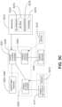
- a data communication interface 4280 is provided, and is connected to the central controller 4230.
- Data communication interface 4280 may be connectable to a remote external communication network 4282 and/or a local external communication network 4284.
- the remote external communication network 4282 may be connectable to a remote external device 4286.
- the local external communication network 4284 may be connectable to a local external device 4288.
- data communication interface 4280 is part of the central controller 4230. In another form, data communication interface 4280 is separate from the central controller 4230, and may comprise an integrated circuit or a processor.
- remote external communication network 4282 is the Internet.
- the data communication interface 4280 may use wired communication (e.g. via Ethernet, or optical fibre) or a wireless protocol (e.g. CDMA, GSM, LTE) to connect to the Internet.
- wired communication e.g. via Ethernet, or optical fibre
- a wireless protocol e.g. CDMA, GSM, LTE
- local external communication network 4284 utilises one or more communication standards, such as Bluetooth, or a consumer infrared protocol.
- remote external device 4286 is one or more computers, for example a cluster of networked computers.
- remote external device 4286 may be virtual computers, rather than physical computers. In either case, such a remote external device 4286 may be accessible to an appropriately authorised person such as a clinician.
- the local external device 4288 may be a personal computer, mobile phone, tablet or remote control.
- An output device 4290 in accordance with the present technology may take the form of one or more of a visual, audio and haptic unit.
- a visual display may be a Liquid Crystal Display (LCD) or Light Emitting Diode (LED) display.
- a display driver 4292 receives as an input the characters, symbols, or images intended for display on the display 4294, and converts them to commands that cause the display 4294 to display those characters, symbols, or images.
- a display 4294 is configured to visually display characters, symbols, or images in response to commands received from the display driver 4292.
- the display 4294 may be an eight-segment display, in which case the display driver 4292 converts each character or symbol, such as the figure "0", to eight logical signals indicating whether the eight respective segments are to be activated to display a particular character or symbol.
- An air circuit 4170 in accordance with an aspect of the present technology is a conduit or a tube constructed and arranged to allow, in use, a flow of air to travel between two components such as RPT device 4000 and the patient interface 3000.
- the air circuit 4170 may be in fluid connection with the outlet of the pneumatic block 4020 and the patient interface.
- the air circuit may be referred to as an air delivery tube. In some cases there may be separate limbs of the circuit for inhalation and exhalation. In other cases a single limb is used.
- supplemental oxygen 4180 is delivered to one or more points in the pneumatic path, such as upstream of the pneumatic block 4020, to the air circuit 4170 and/or to the patient interface 3000.
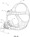
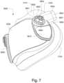
- a humidifier 5000 (e.g. as shown in Fig. 5A ) to change the absolute humidity of air or gas for delivery to a patient relative to ambient air.
- the humidifier 5000 is used to increase the absolute humidity and increase the temperature of the flow of air (relative to ambient air) before delivery to the patient's airways.
- the humidifier 5000 may comprise a humidifier reservoir 5110, a humidifier inlet 5002 to receive a flow of air, and a humidifier outlet 5004 to deliver a humidified flow of air.
- a humidifier reservoir 5110 may be the humidifier inlet 5002 and the humidifier outlet 5004 respectively.
- the humidifier 5000 may further comprise a humidifier base 5006, which may be adapted to receive the humidifier reservoir 5110 and comprise a heating element 5240.
- the water reservoir 5110 is configured to add humidity to a flow of air from the RPT device 4000 as the flow of air travels therethrough.
- the water reservoir 5110 may be configured to encourage the flow of air to travel in a tortuous path through the reservoir 5110 while in contact with the volume of water therein.
- the reservoir 5110 may be removable from the humidifier 5000, for example in a lateral direction as shown in Fig. 5A and Fig. 5B .
- the reservoir 5110 comprises a conductive portion 5120 configured to allow efficient transfer of heat from the heating element 5240 to the volume of liquid in the reservoir 5110.
- the conductive portion 5120 may be arranged as a plate, although other shapes may also be suitable. All or a part of the conductive portion 5120 may be made of a thermally conductive material such as aluminium (e.g. approximately 2 mm thick, such as 1 mm, 1.5 mm, 2.5 mm or 3 mm), another heat conducting metal or some plastics. In some cases, suitable heat conductivity may be achieved with less conductive materials of suitable geometry.
- the humidifier 5000 may comprise a humidifier reservoir dock 5130 (as shown in Fig. 5B ) configured to receive the humidifier reservoir 5110.
- the humidifier reservoir dock 5130 may comprise a locking feature such as a locking lever 5135 configured to retain the reservoir 5110 in the humidifier reservoir dock 5130.
- the humidifier reservoir 5110 may comprise a water level indicator 5150 as shown in Fig. 5A-5B .
- the water level indicator 5150 may provide one or more indications to a user such as the patient 1000 or a care giver regarding a quantity of the volume of water in the humidifier reservoir 5110.
- the one or more indications provided by the water level indicator 5150 may include an indication of a maximum, predetermined volume of water, any portions thereof, such as 25%, 50% or 75% or volumes such as 200 ml, 300 ml or 400ml.
- the humidifier 5000 may comprise one or more humidifier transducers (sensors) 5210 instead of, or in addition to, transducers 4270 described above.
- Humidifier transducers 5210 may include one or more of an air pressure sensor 5212, an air flow rate transducer 5214, a temperature sensor 5216, or a humidity sensor 5218 as shown in Fig. 5C .
- a humidifier transducer 5210 may produce one or more output signals which may be communicated to a controller such as the central controller 4230 and/or the humidifier controller 5250.
- a humidifier transducer may be located externally to the humidifier 5000 (such as in the air circuit 4170) while communicating the output signal to the controller.
- One or more pressure transducers 5212 may be provided to the humidifier 5000 in addition to, or instead of, a pressure sensor 4272 provided in the RPT device 4000.
- One or more flow rate transducers 5214 may be provided to the humidifier 5000 in addition to, or instead of, a flow rate sensor 4274 provided in the RPT device 4000.
- the humidifier 5000 may comprise one or more temperature transducers 5216.
- the one or more temperature transducers 5216 may be configured to measure one or more temperatures such as of the heating element 5240 and/or of the flow of air downstream of the humidifier outlet 5004.
- the humidifier 5000 may further comprise a temperature sensor 5216 to detect the temperature of the ambient air.
- the humidifier 5000 may comprise one or more humidity sensors 5218 to detect a humidity of a gas, such as the ambient air.
- the humidity sensor 5218 may be placed towards the humidifier outlet 5004 in some forms to measure a humidity of the gas delivered from the humidifier 5000.
- the humidity sensor may be an absolute humidity sensor or a relative humidity sensor.
- a heating element 5240 may be provided to the humidifier 5000 in some cases to provide a heat input to one or more of the volume of water in the humidifier reservoir 5110 and/or to the flow of air.
- the heating element 5240 may comprise a heat generating component such as an electrically resistive heating track.
- One suitable example of a heating element 5240 is a layered heating element such as one described in the PCT Patent Application Publication No. WO 2012/171072 .
- the heating element 5240 may be provided in the humidifier base 5006 where heat may be provided to the humidifier reservoir 5110 primarily by conduction as shown in Fig. 5B .
- a humidifier 5000 may comprise a humidifier controller 5250 as shown in Fig. 5C .
- the humidifier controller 5250 may be a part of the central controller 4230.
- the humidifier controller 5250 may be a separate controller, which may be in communication with the central controller 4230.
- the humidifier controller 5250 may receive as inputs measures of properties (such as temperature, humidity, pressure and/or flow rate), for example of the flow of air, the water in the reservoir 5110 and/or the humidifier 5000.
- the humidifier controller 5250 may also be configured to execute or implement humidifier algorithms and/or deliver one or more output signals.
- the humidifier controller 5250 may comprise one or more controllers, such as a central humidifier controller 5251, a heated air circuit controller 5254 configured to control the temperature of a heated air circuit 4170 and/or a heating element controller 5252 configured to control the temperature of a heating element 5240.
- Fig. 6A shows a model typical breath waveform of a person while sleeping.
- the horizontal axis is time, and the vertical axis is respiratory flow rate.
- a typical breath may have the following approximate values: tidal volume Vt 0.5L, inhalation time Ti 1.6s, peak inspiratory flow rate Qpeak 0.4 L/s, exhalation time Te 2.4s, peak expiratory flow rate Qpeak - 0.5 L/s.
- the total duration of the breath, Ttot is about 4s.
- the person typically breathes at a rate of about 15 breaths per minute (BPM), with Ventilation Vent about 7.5 L/min.
- a typical duty cycle, the ratio of Ti to Ttot is about 40%.
- Air In certain forms of the present technology, air may be taken to mean atmospheric air, and in other forms of the present technology air may be taken to mean some other combination of breathable gases, e.g. atmospheric air enriched with oxygen.
- ambient In certain forms of the present technology, the term ambient will be taken to mean (i) external of the treatment system or patient, and (ii) immediately surrounding the treatment system or patient.
- ambient pressure may be the pressure immediately surrounding or external to the body.
- ambient noise may be considered to be the background noise level in the room where a patient is located, other than for example, noise generated by an RPT device or emanating from a mask or patient interface.
- Ambient noise may be generated by sources outside the room.
- APAP therapy in which the treatment pressure is automatically adjustable, e.g. from breath to breath, between minimum and maximum limits, depending on the presence or absence of indications of SDB events.
- Continuous Positive Airway Pressure (CPAP) therapy Respiratory pressure therapy in which the treatment pressure is approximately constant through a respiratory cycle of a patient.
- the pressure at the entrance to the airways will be slightly higher during exhalation, and slightly lower during inhalation.
- the pressure will vary between different respiratory cycles of the patient, for example, being increased in response to detection of indications of partial upper airway obstruction, and decreased in the absence of indications of partial upper airway obstruction.
- Flow rate The volume (or mass) of air delivered per unit time. Flow rate may refer to an instantaneous quantity. In some cases, a reference to flow rate will be a reference to a scalar quantity, namely a quantity having magnitude only. In other cases, a reference to flow rate will be a reference to a vector quantity, namely a quantity having both magnitude and direction. Flow rate may be given the symbol Q. 'Flow rate' is sometimes shortened to simply 'flow' or 'airflow'.
- a flow rate may be nominally positive for the inspiratory portion of a breathing cycle of a patient, and hence negative for the expiratory portion of the breathing cycle of a patient.
- Total flow rate, Qt is the flow rate of air leaving the RPT device.
- Vent flow rate, Qv is the flow rate of air leaving a vent to allow washout of exhaled gases.
- Leak flow rate, Ql is the flow rate of leak from a patient interface system or elsewhere.
- Respiratory flow rate, Qr is the flow rate of air that is received into the patient's respiratory system.
- Humidifier The word humidifier will be taken to mean a humidifying apparatus constructed and arranged, or configured with a physical structure to be capable of providing a therapeutically beneficial amount of water (H 2 O) vapour to a flow of air to ameliorate a medical respiratory condition of a patient.
- H 2 O water
- Leak The word leak will be taken to be an unintended flow of air. In one example, leak may occur as the result of an incomplete seal between a mask and a patient's face. In another example leak may occur in a swivel elbow to the ambient.
- Conducted noise in the present document refers to noise which is carried to the patient by the pneumatic path, such as the air circuit and the patient interface as well as the air therein.
- conducted noise may be quantified by measuring sound pressure levels at the end of an air circuit.
- Radiated noise in the present document refers to noise which is carried to the patient by the ambient air.
- radiated noise may be quantified by measuring sound power/pressure levels of the object in question according to ISO 3744.
- Vent noise in the present document refers to noise which is generated by the flow of air through any vents such as vent holes of the patient interface.
- Patient A person, whether or not they are suffering from a respiratory condition.
- Pressure Force per unit area. Pressure may be expressed in a range of units, including cmH 2 O, g-f/cm 2 and hectopascal. 1 cmH 2 O is equal to 1 g-f/cm 2 and is approximately 0.98 hectopascal. In this specification, unless otherwise stated, pressure is given in units of cmH 2 O.
- the pressure in the patient interface is given the symbol Pm
- the treatment pressure which represents a target value to be achieved by the mask pressure Pm at the current instant of time, is given the symbol Pt.
- Respiratory Pressure Therapy The application of a supply of air to an entrance to the airways at a treatment pressure that is typically positive with respect to atmosphere.
- Ventilator A mechanical device that provides pressure support to a patient to perform some or all of the work of breathing.
- Silicone or Silicone Elastomer A synthetic rubber.
- a reference to silicone is a reference to liquid silicone rubber (LSR) or a compression moulded silicone rubber (CMSR).
- LSR liquid silicone rubber
- CMSR compression moulded silicone rubber
- SILASTIC included in the range of products sold under this trademark
- Another manufacturer of LSR is Wacker.
- an exemplary form of LSR has a Shore A (or Type A) indentation hardness in the range of about 35 to about 45 as measured using ASTM D2240.
- Polycarbonate a thermoplastic polymer of Bisphenol-A Carbonate.
- Resilience Ability of a material to absorb energy when deformed elastically and to release the energy upon unloading.
- Resilient Will release substantially all of the energy when unloaded. Includes e.g. certain silicones, and thermoplastic elastomers.
- Hardness The ability of a material per se to resist deformation (e.g. described by a Young's Modulus, or an indentation hardness scale measured on a standardised sample size).
- Stiffness (or rigidity) of a structure or component The ability of the structure or component to resist deformation in response to an applied load.
- the load may be a force or a moment, e.g. compression, tension, bending or torsion.
- the structure or component may offer different resistances in different directions.
- Floppy structure or component A structure or component that will change shape, e.g. bend, when caused to support its own weight, within a relatively short period of time such as 1 second.
- Rigid structure or component A structure or component that will not substantially change shape when subject to the loads typically encountered in use.
- An example of such a use may be setting up and maintaining a patient interface in sealing relationship with an entrance to a patient's airways, e.g. at a load of approximately 20 to 30 cmH 2 O pressure.
- an I-beam may comprise a different bending stiffness (resistance to a bending load) in a first direction in comparison to a second, orthogonal direction.
- a structure or component may be floppy in a first direction and rigid in a second direction.
- an apnea is said to have occurred when flow falls below a predetermined threshold for a duration, e.g. 10 seconds.
- An obstructive apnea will be said to have occurred when, despite patient effort, some obstruction of the airway does not allow air to flow.
- a central apnea will be said to have occurred when an apnea is detected that is due to a reduction in breathing effort, or the absence of breathing effort, despite the airway being patent.
- a mixed apnea occurs when a reduction or absence of breathing effort coincides with an obstructed airway.
- Breathing rate The rate of spontaneous respiration of a patient, usually measured in breaths per minute.
- Duty cycle The ratio of inhalation time, Ti to total breath time, Ttot.
- Effort The work done by a spontaneously breathing person attempting to breathe.
- Expiratory portion of a breathing cycle The period from the start of expiratory flow to the start of inspiratory flow.
- Flow limitation will be taken to be the state of affairs in a patient's respiration where an increase in effort by the patient does not give rise to a corresponding increase in flow. Where flow limitation occurs during an inspiratory portion of the breathing cycle it may be described as inspiratory flow limitation. Where flow limitation occurs during an expiratory portion of the breathing cycle it may be described as expiratory flow limitation.
- hypopnea is taken to be a reduction in flow, but not a cessation of flow.
- a hypopnea may be said to have occurred when there is a reduction in flow below a threshold rate for a duration.
- a central hypopnea will be said to have occurred when a hypopnea is detected that is due to a reduction in breathing effort.
- hypopneas either of the following may be regarded as being hypopneas:
- Hyperpnea An increase in flow to a level higher than normal.
- Inspiratory portion of a breathing cycle The period from the start of inspiratory flow to the start of expiratory flow will be taken to be the inspiratory portion of a breathing cycle.
- Patency The degree of the airway being open, or the extent to which the airway is open. A patent airway is open. Airway patency may be quantified, for example with a value of one (1) being patent, and a value of zero (0), being closed (obstructed).
- PEEP Positive End-Expiratory Pressure
- Peak flow rate (Qpeak) The maximum value of flow rate during the inspiratory portion of the respiratory flow waveform.
- Tidal volume (Vt) The volume of air inhaled or exhaled during normal breathing, when extra effort is not applied.
- the inspiratory volume Vi (the volume of air inhaled) is equal to the expiratory volume Ve (the volume of air exhaled), and therefore a single tidal volume Vt may be defined as equal to either quantity.
- the tidal volume Vt is estimated as some combination, e.g. the mean, of the inspiratory volume Vi and the expiratory volume Ve.
- Ttot Total Time
- Typical recent ventilation The value of ventilation around which recent values of ventilation Vent over some predetermined timescale tend to cluster, that is, a measure of the central tendency of the recent values of ventilation.
- Upper airway obstruction includes both partial and total upper airway obstruction. This may be associated with a state of flow limitation, in which the flow rate increases only slightly or may even decrease as the pressure difference across the upper airway increases (Starling resistor behaviour).
- Ventilation A measure of a rate of gas being exchanged by the patient's respiratory system. Measures of ventilation may include one or both of inspiratory and expiratory flow, per unit time. When expressed as a volume per minute, this quantity is often referred to as "minute ventilation”. Minute ventilation is sometimes given simply as a volume, understood to be the volume per minute.
- Adaptive Servo-Ventilator A servo-ventilator that has a changeable, rather than fixed target ventilation.
- the changeable target ventilation may be learned from some characteristic of the patient, for example, a respiratory characteristic of the patient.
- a parameter of a ventilator that establishes the minimum breathing rate (typically in number of breaths per minute) that the ventilator will deliver to the patient, if not triggered by spontaneous respiratory effort.
- Expiratory positive airway pressure a base pressure, to which a pressure varying within the breath is added to produce the desired mask pressure which the ventilator will attempt to achieve at a given time.
- Inspiratory positive airway pressure (IPAP): Maximum desired mask pressure which the ventilator will attempt to achieve during the inspiratory portion of the breath.
- pressure support means the difference which the ventilator aims to achieve, rather than what it actually achieves.
- Servo-ventilator A ventilator that measures patient ventilation, has a target ventilation, and which adjusts the level of pressure support to bring the patient ventilation towards the target ventilation.
- Spontaneous/Timed A mode of a ventilator or other device that attempts to detect the initiation of a breath of a spontaneously breathing patient. If however, the device is unable to detect a breath within a predetermined period of time, the device will automatically initiate delivery of the breath.
- Triggered When a ventilator delivers a breath of air to a spontaneously breathing patient, it is said to be triggered to do so at the initiation of the respiratory portion of the breathing cycle by the patient's efforts.
- Ala the external outer wall or "wing" of each nostril (plural: alar)
- Alare The most lateral point on the nasal ala.
- Alar curvature (or alar crest) point The most posterior point in the curved base line of each ala , found in the crease formed by the union of the ala with the cheek.
- Auricle The whole external visible part of the ear.
- (nose) Bony framework The bony framework of the nose comprises the nasal bones, the frontal process of the maxillae and the nasal part of the frontal bone.
- (nose) Cartilaginous framework The cartilaginous framework of the nose comprises the septal, lateral, major and minor cartilages.
- Columella the strip of skin that separates the nares and which runs from the pronasale to the upper lip.
- Columella angle The angle between the line drawn through the midpoint of the nostril aperture and a line drawn perpendicular to the Frankfort horizontal while intersecting subnasale.
- Frankfort horizontal plane A line extending from the most inferior point of the orbital margin to the left tragion.
- the tragion is the deepest point in the notch superior to the tragus of the auricle.
- Glabella Located on the soft tissue, the most prominent point in the midsagittal plane of the forehead.
- Lateral nasal cartilage A generally triangular plate of cartilage. Its superior margin is attached to the nasal bone and frontal process of the maxilla, and its inferior margin is connected to the greater alar cartilage.
- Greater alar cartilage A plate of cartilage lying below the lateral nasal cartilage. It is curved around the anterior part of the naris. Its posterior end is connected to the frontal process of the maxilla by a tough fibrous membrane containing three or four minor cartilages of the ala.
- Nares Nostrils: Approximately ellipsoidal apertures forming the entrance to the nasal cavity.
- the singular form of nares is naris (nostril). The nares are separated by the nasal septum.
- Naso-labial sulcus or Naso-labial fold The skin fold or groove that runs from each side of the nose to the corners of the mouth, separating the cheeks from the upper lip.
- Naso-labial angle The angle between the columella and the upper lip, while intersecting subnasale.
- Otobasion inferior The lowest point of attachment of the auricle to the skin of the face.
- Otobasion superior The highest point of attachment of the auricle to the skin of the face.
- Pronasale the most protruded point or tip of the nose, which can be identified in lateral view of the rest of the portion of the head.
- Philtrum the midline groove that runs from lower border of the nasal septum to the top of the lip in the upper lip region.
- Pogonion Located on the soft tissue, the most anterior midpoint of the chin.
- nasal Ridge The nasal ridge is the midline prominence of the nose, extending from the Sellion to the Pronasale.
- Sagittal plane A vertical plane that passes from anterior (front) to posterior (rear).
- the midsagittal plane is a sagittal plane that divides the body into right and left halves.
- Septal cartilage (nasal): The nasal septal cartilage forms part of the septum and divides the front part of the nasal cavity.
- Subalare The point at the lower margin of the alar base, where the alar base joins with the skin of the superior (upper) lip.
- Subnasal point Located on the soft tissue, the point at which the columella merges with the upper lip in the midsagittal plane.
- Frontal bone The frontal bone includes a large vertical portion, the squama frontalis , corresponding to the region known as the forehead.
- Mandible forms the lower jaw.
- the mental protuberance is the bony protuberance of the jaw that forms the chin.
- Maxilla The maxilla forms the upper jaw and is located above the mandible and below the orbits. The frontal process of the maxilla projects upwards by the side of the nose, and forms part of its lateral boundary.
- Nasal bones The nasal bones are two small oblong bones, varying in size and form in different individuals; they are placed side by side at the middle and upper part of the face, and form, by their junction, the "bridge" of the nose.
- Nasion The intersection of the frontal bone and the two nasal bones, a depressed area directly between the eyes and superior to the bridge of the nose.
- Occipital bone The occipital bone is situated at the back and lower part of the cranium. It includes an oval aperture, the foramen magnum , through which the cranial cavity communicates with the vertebral canal.
- the curved plate behind the foramen magnum is the squama occipitalis.
- Orbit The bony cavity in the skull to contain the eyeball.
- the parietal bones are the bones that, when joined together, form the roof and sides of the cranium.
- Temporal bones The temporal bones are situated on the bases and sides of the skull, and support that part of the face known as the temple.
- Zygomatic bones The face includes two zygomatic bones, located in the upper and lateral parts of the face and forming the prominence of the cheek.
- Diaphragm A sheet of muscle that extends across the bottom of the rib cage. The diaphragm separates the thoracic cavity, containing the heart, lungs and ribs, from the abdominal cavity. As the diaphragm contracts the volume of the thoracic cavity increases and air is drawn into the lungs.
- Larynx The larynx, or voice box houses the vocal folds and connects the inferior part of the pharynx (hypopharynx) with the trachea.
- Lungs The organs of respiration in humans.
- the conducting zone of the lungs contains the trachea, the bronchi, the bronchioles, and the terminal bronchioles.
- the respiratory zone contains the respiratory bronchioles, the alveolar ducts, and the alveoli.
- Nasal cavity The nasal cavity (or nasal fossa) is a large air filled space above and behind the nose in the middle of the face.
- the nasal cavity is divided in two by a vertical fin called the nasal septum.
- On the sides of the nasal cavity are three horizontal outgrowths called nasal conchae (singular "concha") or turbinates.
- nasal conchae singular "concha”
- turbinates To the front of the nasal cavity is the nose, while the back blends, via the choanae, into the nasopharynx.
- Pharynx The part of the throat situated immediately inferior to (below) the nasal cavity, and superior to the oesophagus and larynx.
- the pharynx is conventionally divided into three sections: the nasopharynx (epipharynx) (the nasal part of the pharynx), the oropharynx (mesopharynx) (the oral part of the pharynx), and the laryngopharynx (hypopharynx).
- Anti-asphyxia valve The component or sub-assembly of a mask system that, by opening to atmosphere in a failsafe manner, reduces the risk of excessive CO 2 rebreathing by a patient.
- an elbow is an example of a structure that directs an axis of flow of air travelling therethrough to change direction through an angle.
- the angle may be approximately 90 degrees.
- the angle may be more, or less than 90 degrees.
- the elbow may have an approximately circular cross-section.
- the elbow may have an oval or a rectangular cross-section.
- an elbow may be rotatable with respect to a mating component, e.g. about 360 degrees.
- an elbow may be removable from a mating component, e.g. via a snap connection.
- an elbow may be assembled to a mating component via a one-time snap during manufacture, but not removable by a patient.
- Frame will be taken to mean a mask structure that bears the load of tension between two or more points of connection with a headgear.
- a mask frame may be a non-airtight load bearing structure in the mask. However, some forms of mask frame may also be air-tight.
- Headgear will be taken to mean a form of positioning and stabilizing structure designed for use on a head.
- the headgear may comprise a collection of one or more struts, ties and stiffeners configured to locate and retain a patient interface in position on a patient's face for delivery of respiratory therapy.
- Some ties are formed of a soft, flexible, elastic material such as a laminated composite of foam and fabric.
- Membrane will be taken to mean a typically thin element that has, preferably, substantially no resistance to bending, but has resistance to being stretched.
- Plenum chamber a mask plenum chamber will be taken to mean a portion of a patient interface having walls at least partially enclosing a volume of space, the volume having air therein pressurised above atmospheric pressure in use.
- a shell may form part of the walls of a mask plenum chamber.
- Seal May be a noun form ("a seal”) which refers to a structure, or a verb form ("to seal”) which refers to the effect.
- a seal noun form
- to seal to seal
- Two elements may be constructed and/or arranged to 'seal' or to effect 'sealing' therebetween without requiring a separate 'seal' element per se.
- a shell will be taken to mean a curved, relatively thin structure having bending, tensile and compressive stiffness.
- a curved structural wall of a mask may be a shell.
- a shell may be faceted.
- a shell may be airtight.
- a shell may not be airtight.
- a stiffener will be taken to mean a structural component designed to increase the bending resistance of another component in at least one direction.
- a strut will be taken to be a structural component designed to increase the compression resistance of another component in at least one direction.
- Swivel A subassembly of components configured to rotate about a common axis, preferably independently, preferably under low torque.
- the swivel may be constructed to rotate through an angle of at least 360 degrees.
- the swivel may be constructed to rotate through an angle less than 360 degrees.
- the sub-assembly of components preferably comprises a matched pair of cylindrical conduits. There may be little or no leak flow of air from the swivel in use.
- Tie A structure designed to resist tension.
- Vent (noun): A structure that allows a flow of air from an interior of the mask, or conduit, to ambient air for clinically effective washout of exhaled gases.
- a clinically effective washout may involve a flow rate of about 10 litres per minute to about 100 litres per minute, depending on the mask design and treatment pressure.
- Products in accordance with the present technology may comprise one or more three-dimensional mechanical structures, for example a mask cushion or an impeller.
- the three-dimensional structures may be bounded by two-dimensional surfaces. These surfaces may be distinguished using a label to describe an associated surface orientation, location, function, or some other characteristic.
- a structure may comprise one or more of an anterior surface, a posterior surface, an interior surface and an exterior surface.
- a seal-forming structure may comprise a face-contacting (e.g. outer) surface, and a separate non-face-contacting (e.g. underside or inner) surface.
- a structure may comprise a first surface and a second surface.
- Fig. 3B to Fig. 3F illustrate examples of cross-sections at point p on a surface, and the resulting plane curves.
- Figs. 3B to 3F also illustrate an outward normal vector at p.
- the outward normal vector at p points away from the surface.
- the curvature of a plane curve at p may be described as having a sign (e.g. positive, negative) and a magnitude (e.g. 1/radius of a circle that just touches the curve at p ).
- Negative curvature If the curve at p turns away from the outward normal, the curvature in that direction at that point will be taken to be negative (if the imaginary small person leaves the point p they must walk downhill). See Fig. 3E (relatively small negative curvature compared to Fig. 3F) and Fig. 3F (relatively large negative curvature compared to Fig. 3E ). Such curves are often referred to as convex.
- a description of the shape at a given point on a two-dimensional surface in accordance with the present technology may include multiple normal cross-sections.
- the multiple cross-sections may cut the surface in a plane that includes the outward normal (a "normal plane"), and each cross-section may be taken in a different direction.
- Each cross-section results in a plane curve with a corresponding curvature.
- the different curvatures at that point may have the same sign, or a different sign.
- Each of the curvatures at that point has a magnitude, e.g. relatively small.
- the plane curves in Figs. 3B to 3F could be examples of such multiple cross-sections at a particular point.
- Principal curvatures and directions The directions of the normal planes where the curvature of the curve takes its maximum and minimum values are called the principal directions.
- the maximum curvature occurs in Fig. 3B
- the minimum occurs in Fig. 3F
- Fig. 3B and Fig. 3F are cross sections in the principal directions.
- the principal curvatures at p are the curvatures in the principal directions.
- Region of a surface A connected set of points on a surface.
- the set of points in a region may have similar characteristics, e.g. curvatures or signs.
- Saddle region A region where at each point, the principal curvatures have opposite signs, that is, one is positive, and the other is negative (depending on the direction to which the imaginary person turns, they may walk uphill or downhill).
- Dome region A region where at each point the principal curvatures have the same sign, e.g. both positive (a "concave dome”) or both negative (a “convex dome”).
- Cylindrical region A region where one principal curvature is zero (or, for example, zero within manufacturing tolerances) and the other principal curvature is non-zero.
- Planar region A region of a surface where both of the principal curvatures are zero (or, for example, zero within manufacturing tolerances).
- Edge of a surface A boundary or limit of a surface or region.
- 'path' will be taken to mean a path in the mathematical - topological sense, e.g. a continuous space curve from f(0) to f(1) on a surface.
- a 'path' may be described as a route or course, including e.g. a set of points on a surface. (The path for the imaginary person is where they walk on the surface, and is analogous to a garden path).
- Path length In certain forms of the present technology, 'path length' will be taken to mean the distance along the surface from f(0) to f(1), that is, the distance along the path on the surface. There may be more than one path between two points on a surface and such paths may have different path lengths. (The path length for the imaginary person would be the distance they have to walk on the surface along the path).
- the straight-line distance is the distance between two points on a surface, but without regard to the surface. On planar regions, there would be a path on the surface having the same path length as the straight-line distance between two points on the surface. On non-planar surfaces, there may be no paths having the same path length as the straight-line distance between two points. (For the imaginary person, the straight-line distance would correspond to the distance ⁇ as the crow flies'.)
- a space curve does not necessarily lie in any particular plane.
- a space curve may be closed, that is, having no endpoints.
- a space curve may be considered to be a one-dimensional piece of three-dimensional space.
- An imaginary person walking on a strand of the DNA helix walks along a space curve.
- a typical human left ear comprises a helix, which is a left-hand helix, see Fig. 3Q .
- a typical human right ear comprises a helix, which is a right-hand helix, see Fig. 3R.
- Fig. 3S shows a right-hand helix.
- the edge of a structure e.g. the edge of a membrane or impeller, may follow a space curve.
- a space curve may be described by a curvature and a torsion at each point on the space curve.
- Torsion is a measure of how the curve turns out of a plane. Torsion has a sign and a magnitude.
- the torsion at a point on a space curve may be characterised with reference to the tangent, normal and binormal vectors at that point.
- Tangent unit vector (or unit tangent vector): For each point on a curve, a vector at the point specifies a direction from that point, as well as a magnitude. A tangent unit vector is a unit vector pointing in the same direction as the curve at that point. If an imaginary person were flying along the curve and fell off her vehicle at a particular point, the direction of the tangent vector is the direction she would be travelling.
- Unit normal vector As the imaginary person moves along the curve, this tangent vector itself changes.
- the unit vector pointing in the same direction that the tangent vector is changing is called the unit principal normal vector. It is perpendicular to the tangent vector.
- Binormal unit vector The binormal unit vector is perpendicular to both the tangent vector and the principal normal vector. Its direction may be determined by a right-hand rule (see e.g. Fig. 3P ), or alternatively by a left-hand rule ( Fig. 3O ).
- Osculating plane The plane containing the unit tangent vector and the unit principal normal vector. See Figures 3O and 3P .
- Torsion of a space curve is the magnitude of the rate of change of the binormal unit vector at that point. It measures how much the curve deviates from the osculating plane.
- a space curve which lies in a plane has zero torsion.
- a space curve which deviates a relatively small amount from the osculating plane will have a relatively small magnitude of torsion (e.g. a gently sloping helical path).
- a space curve which deviates a relatively large amount from the osculating plane will have a relatively large magnitude of torsion (e.g. a steeply sloping helical path).
- T2>T1 the magnitude of the torsion near the top coils of the helix of Fig. 3S is greater than the magnitude of the torsion of the bottom coils of the helix of Fig. 3S
- a space curve turning towards the direction of the right-hand binormal may be considered as having a right-hand positive torsion (e.g. a right-hand helix as shown in Fig. 3S ).
- a space curve turning away from the direction of the right-hand binormal may be considered as having a right-hand negative torsion (e.g. a left-hand helix).
- a space curve turning towards the direction of the left-hand binormal may be considered as having a left-hand positive torsion (e.g. a left-hand helix).
- left-hand positive is equivalent to right-hand negative. See Fig. 3T .
- a surface may have a one-dimensional hole, e.g. a hole bounded by a plane curve or by a space curve.
- Thin structures e.g. a membrane
- Thin structures with a hole, may be described as having a one-dimensional hole. See for example the one dimensional hole in the surface of structure shown in Fig. 3I , bounded by a plane curve.
- a structure may have a two-dimensional hole, e.g. a hole bounded by a surface.
- a hole bounded by a surface For example, an inflatable tyre has a two dimensional hole bounded by the interior surface of the tyre.
- a bladder with a cavity for air or gel could have a two-dimensional hole. See for example the cushion of Fig. 3L and the example cross-sections therethrough in Fig. 3M and Fig. 3N , with the interior surface bounding a two dimensional hole indicated.
- a conduit may comprise a one-dimension hole (e.g. at its entrance or at its exit), and a two-dimension hole bounded by the inside surface of the conduit. See also the two dimensional hole through the structure shown in Fig. 3K , bounded by a surface as shown.
- any and all components herein described are understood to be capable of being manufactured and, as such, may be manufactured together or separately.
Landscapes
- Health & Medical Sciences (AREA)
- Pulmonology (AREA)
- Life Sciences & Earth Sciences (AREA)
- Animal Behavior & Ethology (AREA)
- Anesthesiology (AREA)
- Biomedical Technology (AREA)
- Heart & Thoracic Surgery (AREA)
- Hematology (AREA)
- Emergency Medicine (AREA)
- Engineering & Computer Science (AREA)
- General Health & Medical Sciences (AREA)
- Public Health (AREA)
- Veterinary Medicine (AREA)
- Otolaryngology (AREA)
- Orthopedics, Nursing, And Contraception (AREA)
- Measurement Of The Respiration, Hearing Ability, Form, And Blood Characteristics Of Living Organisms (AREA)
- Accommodation For Nursing Or Treatment Tables (AREA)
Priority Applications (1)
| Application Number | Priority Date | Filing Date | Title |
|---|---|---|---|
| EP25154064.7A EP4570291A3 (en) | 2017-12-22 | 2018-12-21 | Conduit headgear connector for patient interface |
Applications Claiming Priority (3)
| Application Number | Priority Date | Filing Date | Title |
|---|---|---|---|
| US201762609909P | 2017-12-22 | 2017-12-22 | |
| EP18890969.1A EP3727543B1 (en) | 2017-12-22 | 2018-12-21 | Conduit headgear connector for patient interface |
| PCT/AU2018/051382 WO2019119058A1 (en) | 2017-12-22 | 2018-12-21 | Conduit headgear connector for patient interface |
Related Parent Applications (1)
| Application Number | Title | Priority Date | Filing Date |
|---|---|---|---|
| EP18890969.1A Division EP3727543B1 (en) | 2017-12-22 | 2018-12-21 | Conduit headgear connector for patient interface |
Related Child Applications (1)
| Application Number | Title | Priority Date | Filing Date |
|---|---|---|---|
| EP25154064.7A Division EP4570291A3 (en) | 2017-12-22 | 2018-12-21 | Conduit headgear connector for patient interface |
Publications (2)
| Publication Number | Publication Date |
|---|---|
| EP4197579A1 EP4197579A1 (en) | 2023-06-21 |
| EP4197579B1 true EP4197579B1 (en) | 2025-01-29 |
Family
ID=66992458
Family Applications (3)
| Application Number | Title | Priority Date | Filing Date |
|---|---|---|---|
| EP25154064.7A Pending EP4570291A3 (en) | 2017-12-22 | 2018-12-21 | Conduit headgear connector for patient interface |
| EP22203609.7A Active EP4197579B1 (en) | 2017-12-22 | 2018-12-21 | Conduit headgear connector for patient interface |
| EP18890969.1A Active EP3727543B1 (en) | 2017-12-22 | 2018-12-21 | Conduit headgear connector for patient interface |
Family Applications Before (1)
| Application Number | Title | Priority Date | Filing Date |
|---|---|---|---|
| EP25154064.7A Pending EP4570291A3 (en) | 2017-12-22 | 2018-12-21 | Conduit headgear connector for patient interface |
Family Applications After (1)
| Application Number | Title | Priority Date | Filing Date |
|---|---|---|---|
| EP18890969.1A Active EP3727543B1 (en) | 2017-12-22 | 2018-12-21 | Conduit headgear connector for patient interface |
Country Status (7)
| Country | Link |
|---|---|
| US (3) | US11173268B2 (enExample) |
| EP (3) | EP4570291A3 (enExample) |
| JP (5) | JP7009633B2 (enExample) |
| CN (2) | CN111511431B (enExample) |
| AU (3) | AU2018390989B2 (enExample) |
| MX (1) | MX2020006669A (enExample) |
| WO (1) | WO2019119058A1 (enExample) |
Families Citing this family (30)
| Publication number | Priority date | Publication date | Assignee | Title |
|---|---|---|---|---|
| CA3195692A1 (en) | 2009-12-23 | 2011-06-30 | Fisher & Paykel Healthcare Limited | An interface and a method of supplying breathing gas |
| EP4570291A3 (en) * | 2017-12-22 | 2025-08-20 | ResMed Pty Ltd | Conduit headgear connector for patient interface |
| CN112292171A (zh) * | 2018-03-28 | 2021-01-29 | 瑞思迈私人有限公司 | 患者接口 |
| WO2020079617A1 (en) | 2018-10-16 | 2020-04-23 | ResMed Pty Ltd | Patient interface |
| US11497875B2 (en) | 2019-02-13 | 2022-11-15 | ResMed Pty Ltd | Textile seal with air-assisted biasing portion |
| EP4438095A3 (en) * | 2019-05-31 | 2024-12-11 | ResMed Pty Ltd | Vent and aav assembly |
| EP3990080B1 (en) * | 2019-06-28 | 2024-11-20 | ResMed Pty Ltd | Seal-forming structure for patient interface including textile seal member |
| US12447304B2 (en) | 2019-06-28 | 2025-10-21 | Resmed Pty, Ltd. | Tube detection systems and methods |
| CN114340707A (zh) * | 2019-07-18 | 2022-04-12 | 费雪派克医疗保健有限公司 | 患者接口 |
| EP4667038A2 (en) | 2019-07-31 | 2025-12-24 | ResMed Pty Ltd | Patient interface having seal-forming structure with varying construction |
| USD941993S1 (en) * | 2019-08-23 | 2022-01-25 | ResMed Pty Ltd | Tube headgear for patient interface |
| WO2021046599A1 (en) * | 2019-09-10 | 2021-03-18 | ResMed Pty Ltd | Oro-nasal patient interface |
| EP4051354B1 (en) | 2019-10-30 | 2025-02-26 | ResMed Pty Ltd | Modular patient interface including a joint coupling mouth and nasal cushions |
| CN114980944A (zh) | 2019-11-29 | 2022-08-30 | 瑞思迈私人有限公司 | 用于患者接口的可调整头带管 |
| EP4090403B1 (en) * | 2020-01-14 | 2025-08-20 | ResMed Pty Ltd | Single flow and pressure activated aav |
| JP7508580B2 (ja) | 2020-04-07 | 2024-07-01 | レスメド・アジア・ピーティーイー・リミテッド | シリコーン層を有する患者インターフェース織物シール |
| US20210338959A1 (en) * | 2020-05-01 | 2021-11-04 | Sonal Asthana | Cpap mask with side ports for providing continuous positively pressurized air to a patient with respiratory distress and other respiratory medical conditions |
| CN116234600A (zh) * | 2020-07-20 | 2023-06-06 | 瑞思迈私人有限公司 | 患者接口和定位和稳定结构 |
| EP4247463A4 (en) * | 2020-11-20 | 2024-10-16 | ResMed Pty Ltd | Vent and aav arrangement for patient interface |
| WO2022133550A1 (en) * | 2020-12-23 | 2022-06-30 | ResMed Pty Ltd | Conduit connector with flow-regulating vent for patient interface |
| DE112022000676T5 (de) * | 2021-01-19 | 2023-11-16 | Fisher & Paykel Healthcare Limited | Patientenschnittstelle |
| CN112925436B (zh) * | 2021-01-22 | 2022-07-08 | 重庆医事通科技发展有限公司 | 基于公共卫生服务健康管理服务无纸化应用系统 |
| AU2022232245A1 (en) * | 2021-03-09 | 2023-09-07 | ResMed Pty Ltd | Full-face patient interface |
| JP2024511542A (ja) * | 2021-03-31 | 2024-03-13 | レスメド・プロプライエタリー・リミテッド | 患者インターフェース用換気配置 |
| EP4154933A1 (en) * | 2021-09-23 | 2023-03-29 | ResMed Pty Ltd | Patient interface for promoting natural breathing |
| WO2023075698A2 (en) * | 2021-10-29 | 2023-05-04 | ResMed Asia Pte. Ltd. | Sleeve with magnet for modularity and headgear for the same |
| US11891808B2 (en) | 2022-01-19 | 2024-02-06 | Oatey Co. | Roof flashing |
| EP4536330A1 (en) * | 2022-06-10 | 2025-04-16 | Koninklijke Philips N.V. | Exhaust diffuser arrangement and cpap mask including same |
| CN120957776A (zh) * | 2023-03-31 | 2025-11-14 | 瑞思迈私人有限公司 | 用于定位和稳定结构的导管及其连接器 |
| CN117731905A (zh) * | 2023-12-29 | 2024-03-22 | 天津怡和嘉业医疗科技有限公司 | 呼吸面罩及医疗设备系统 |
Family Cites Families (63)
| Publication number | Priority date | Publication date | Assignee | Title |
|---|---|---|---|---|
| US1323217A (en) | 1919-11-25 | Ventilating-mask | ||
| US781516A (en) | 1904-02-03 | 1905-01-31 | George N Guthrie Jr | Respirator and inhaler. |
| JPS58500551A (ja) | 1981-04-24 | 1983-04-14 | ソメド プテイ.リミテツド | 鼻マスクのエア供給装置 |
| US4770169A (en) | 1987-02-13 | 1988-09-13 | Mdt Diagnostic Company | Anaesthetic mask |
| US4782832A (en) | 1987-07-30 | 1988-11-08 | Puritan-Bennett Corporation | Nasal puff with adjustable sealing means |
| US5311682A (en) | 1993-01-07 | 1994-05-17 | Sturdivant Charles N | Hybrid dredge |
| US5538000A (en) | 1995-02-06 | 1996-07-23 | Hans Rudolph, Inc. | Airflow delivery system |
| US6158081A (en) * | 1995-11-06 | 2000-12-12 | Bissell Homecare, Inc. | Water extraction cleaning machine with variable solution mixing valve |
| AUPO126596A0 (en) | 1996-07-26 | 1996-08-22 | Resmed Limited | A nasal mask and mask cushion therefor |
| AUPO504597A0 (en) | 1997-02-10 | 1997-03-06 | Resmed Limited | A mask and a vent assembly therefor |
| AUPP366398A0 (en) | 1998-05-22 | 1998-06-18 | Resmed Limited | Ventilatory assistance for treatment of cardiac failure and cheyne-stokes breathing |
| AUPQ102999A0 (en) | 1999-06-18 | 1999-07-08 | Resmed Limited | A connector for a respiratory mask and a respiratory mask |
| US6581594B1 (en) | 2000-05-15 | 2003-06-24 | Resmed Limited | Respiratory mask having gas washout vent and gas washout vent for respiratory mask |
| US6550479B1 (en) | 2000-07-26 | 2003-04-22 | James Neil Duxbury | Personal respirator |
| AU2004212633B2 (en) | 2003-02-21 | 2010-12-09 | ResMed Pty Ltd | Nasal assembly |
| DE202004021829U1 (de) | 2003-05-02 | 2011-05-26 | ResMed Ltd., New South Wales | Ein Maskensystem |
| AU2004308536B2 (en) * | 2003-12-31 | 2011-06-23 | ResMed Pty Ltd | Compact oronasal patient interface |
| NZ550348A (en) | 2004-04-09 | 2011-02-25 | Resmed Ltd | Nasal assembly with vent and baffle |
| DE102005041716B4 (de) | 2004-09-03 | 2025-06-18 | Löwenstein Medical Technology S.A. | Vorrichtung zur Beatmung |
| ES2556590T3 (es) | 2005-01-12 | 2016-01-19 | Resmed Limited | Cojín para interfaz de paciente |
| CN107320833B (zh) * | 2005-06-06 | 2022-06-03 | 瑞思迈私人有限公司 | 面罩系统 |
| DE102005033650B4 (de) * | 2005-07-19 | 2017-06-14 | Resmed R&D Germany Gmbh | Atemmaskeneinrichtung und Verfahren zur Herstellung derselben |
| WO2007045008A1 (en) * | 2005-10-17 | 2007-04-26 | Resmed Limited | Anti-asphyxia valve assembly for respiratory mask |
| NZ577485A (en) | 2006-05-24 | 2011-01-28 | Resmed Ltd | Compact low noise efficient blower for CPAP devices with a shield to prevent a line-of-sight path within |
| EP3628360B1 (en) * | 2006-07-28 | 2024-10-23 | ResMed Pty Ltd | Delivery of respiratory therapy |
| NZ603342A (en) | 2006-10-24 | 2014-08-29 | Resmed Motor Technologies Inc | Vibration isolation system for a respiratory treatment device |
| ES2573432T3 (es) | 2006-12-15 | 2016-06-07 | Resmed Ltd. | Suministro de terapia respiratoria |
| EP2481434B1 (en) | 2006-12-15 | 2016-04-13 | ResMed Ltd. | Delivery of respiratory therapy |
| JP5468747B2 (ja) | 2007-06-05 | 2014-04-09 | レスメド・モーター・テクノロジーズ・インコーポレーテッド | 軸受管を有するブロワ |
| NZ599563A (en) | 2007-07-30 | 2015-01-30 | Resmed Ltd | Patient interface |
| EP3858411B1 (en) | 2007-08-24 | 2024-05-29 | ResMed Pty Ltd | Mask vent |
| US7748751B2 (en) * | 2007-11-01 | 2010-07-06 | Taper-Lok Corporation | Systems and methods for making connections between pipe sections to form a conduit that is substantially free of gaps |
| US8950403B2 (en) | 2008-03-04 | 2015-02-10 | Resmed Limited | Mask system and method for constructing the same |
| CN105126222A (zh) | 2008-06-04 | 2015-12-09 | 瑞思迈有限公司 | 患者接口系统 |
| US10238822B2 (en) * | 2009-05-29 | 2019-03-26 | Resmed Limited | PAP system |
| NZ597254A (en) | 2009-05-29 | 2013-12-20 | Resmed Ltd | Nasal mask system |
| AU2010206053B2 (en) | 2009-07-31 | 2014-08-07 | ResMed Pty Ltd | Wire Heated Tube with Temperature Control System, Tube Type Detection, and Active Over Temperature Protection for Humidifier for Respiratory Apparatus |
| EP4534131A3 (en) * | 2010-09-30 | 2025-05-21 | ResMed Pty Ltd | Patient interface systems |
| US8925548B2 (en) | 2011-05-11 | 2015-01-06 | Carefusion 207, Inc. | Non-invasive ventilation facial skin protection |
| EP3714930B1 (en) | 2011-06-16 | 2023-12-06 | ResMed Pty Ltd | Humidifier with layered heating element |
| CN103764213B (zh) * | 2011-07-08 | 2017-09-26 | 瑞思迈有限公司 | 用于患者接口系统的旋转弯管与连接器组件 |
| EP2731655B1 (en) * | 2011-07-12 | 2017-07-12 | ResMed Limited | Textile mask systems |
| CN103906929B (zh) | 2011-08-05 | 2017-12-15 | 瑞思迈发动机及马达技术股份有限公司 | 鼓风机 |
| US9687620B2 (en) * | 2011-11-07 | 2017-06-27 | Koninklijke Philips N.V. | Patient interface with snap-fit connector |
| AU2012339622B2 (en) * | 2011-11-15 | 2015-04-30 | ResMed Pty Ltd | Nasal mask system |
| CN110075405B (zh) * | 2012-05-18 | 2022-03-29 | 瑞思迈私人有限公司 | 鼻罩系统 |
| CN104661698A (zh) | 2012-08-08 | 2015-05-27 | 费雪派克医疗保健有限公司 | 具有可调弯管的呼吸管组件 |
| AU2014207243B2 (en) * | 2013-01-18 | 2017-02-23 | ResMed Pty Ltd | Patient interface and method for making same |
| TWI696474B (zh) * | 2013-05-14 | 2020-06-21 | 澳大利亞商瑞思邁私人股份有限公司 | 口鼻患者介面 |
| NZ631446A (en) | 2013-10-03 | 2016-05-27 | Resmed Ltd | Mask vent with side wall |
| WO2015179896A1 (en) * | 2014-05-29 | 2015-12-03 | Australasian Steel Products Pty Ltd | Anchoring arrangement for a protective sleeve |
| NZ798329A (en) * | 2014-06-19 | 2024-10-25 | ResMed Pty Ltd | Patient interface for respiratory therapy |
| US10646680B2 (en) | 2014-09-19 | 2020-05-12 | Fisher & Paykel Healthcare Limited | Headgear assemblies and interface assemblies with headgear |
| CN104623784B (zh) | 2015-02-05 | 2018-06-12 | 深圳瑞之谷医疗科技有限公司 | 鼻罩 |
| KR101736280B1 (ko) * | 2015-03-12 | 2017-05-16 | 사회복지법인 삼성생명공익재단 | 관절염 예방 또는 치료용 약학적 조성물 |
| US11266803B2 (en) * | 2015-06-05 | 2022-03-08 | Koninklijke Philips N.V. | Tubing assembly for patient interface device and elements for improving the fit and feel of such assembly |
| JP6907213B2 (ja) | 2015-09-23 | 2021-07-21 | レスメド・プロプライエタリー・リミテッド | 呼吸治療システムのための通気アダプタ |
| EP3865166B1 (en) * | 2015-09-23 | 2024-04-03 | ResMed Pty Ltd | Patient interface |
| CN119792760A (zh) | 2015-09-23 | 2025-04-11 | 瑞思迈私人有限公司 | 弯管组件 |
| CN118079167A (zh) * | 2016-01-14 | 2024-05-28 | 瑞思迈私人有限公司 | 口鼻患者接口 |
| WO2017124152A1 (en) * | 2016-01-21 | 2017-07-27 | Resmed Limited | Adjustable headgear tubing for a patient interface |
| WO2018177794A1 (en) | 2017-03-28 | 2018-10-04 | Koninklijke Philips N.V. | Valve arrangement for full face mask |
| EP4570291A3 (en) | 2017-12-22 | 2025-08-20 | ResMed Pty Ltd | Conduit headgear connector for patient interface |
-
2018
- 2018-12-21 EP EP25154064.7A patent/EP4570291A3/en active Pending
- 2018-12-21 EP EP22203609.7A patent/EP4197579B1/en active Active
- 2018-12-21 AU AU2018390989A patent/AU2018390989B2/en active Active
- 2018-12-21 US US16/955,454 patent/US11173268B2/en active Active
- 2018-12-21 JP JP2020534204A patent/JP7009633B2/ja active Active
- 2018-12-21 MX MX2020006669A patent/MX2020006669A/es unknown
- 2018-12-21 CN CN201880082889.9A patent/CN111511431B/zh active Active
- 2018-12-21 WO PCT/AU2018/051382 patent/WO2019119058A1/en not_active Ceased
- 2018-12-21 CN CN202310488540.8A patent/CN116688307A/zh active Pending
- 2018-12-21 EP EP18890969.1A patent/EP3727543B1/en active Active
-
2021
- 2021-10-07 US US17/496,287 patent/US12311108B2/en active Active
-
2022
- 2022-01-11 JP JP2022002287A patent/JP7302042B2/ja active Active
- 2022-04-06 AU AU2022202305A patent/AU2022202305B2/en active Active
-
2023
- 2023-06-20 JP JP2023101058A patent/JP7505089B2/ja active Active
-
2024
- 2024-06-11 JP JP2024094170A patent/JP2024107281A/ja active Pending
- 2024-06-19 AU AU2024204191A patent/AU2024204191A1/en active Pending
-
2025
- 2025-01-14 US US19/020,253 patent/US20250144344A1/en active Pending
- 2025-07-03 JP JP2025113148A patent/JP2025143413A/ja active Pending
Also Published As
| Publication number | Publication date |
|---|---|
| CN111511431B (zh) | 2023-05-23 |
| JP2024107281A (ja) | 2024-08-08 |
| AU2024204191A1 (en) | 2024-07-11 |
| EP3727543A4 (en) | 2021-08-04 |
| US20220023568A1 (en) | 2022-01-27 |
| AU2022202305B2 (en) | 2024-04-11 |
| US11173268B2 (en) | 2021-11-16 |
| EP3727543B1 (en) | 2022-10-26 |
| EP4570291A3 (en) | 2025-08-20 |
| JP7009633B2 (ja) | 2022-01-25 |
| JP2022046772A (ja) | 2022-03-23 |
| JP2023112056A (ja) | 2023-08-10 |
| AU2018390989A1 (en) | 2020-06-25 |
| JP2021506463A (ja) | 2021-02-22 |
| JP2025143413A (ja) | 2025-10-01 |
| EP4197579A1 (en) | 2023-06-21 |
| MX2020006669A (es) | 2020-08-31 |
| US20200368478A1 (en) | 2020-11-26 |
| WO2019119058A1 (en) | 2019-06-27 |
| AU2022202305A1 (en) | 2022-04-28 |
| JP7302042B2 (ja) | 2023-07-03 |
| JP7505089B2 (ja) | 2024-06-24 |
| CN111511431A (zh) | 2020-08-07 |
| EP3727543A1 (en) | 2020-10-28 |
| US20250144344A1 (en) | 2025-05-08 |
| CN116688307A (zh) | 2023-09-05 |
| EP4570291A2 (en) | 2025-06-18 |
| US12311108B2 (en) | 2025-05-27 |
| AU2018390989B2 (en) | 2022-01-20 |
Similar Documents
| Publication | Publication Date | Title |
|---|---|---|
| AU2022202305B2 (en) | Conduit headgear connector for patient interface | |
| US12090275B2 (en) | Patient interface | |
| AU2023206093B2 (en) | Patient interface | |
| AU2021209178B2 (en) | Patient Interface | |
| EP4021546B1 (en) | Dual chamber patient interface with airflow regulation | |
| EP3976151B1 (en) | Patient interface with a heat and moisture exchanger | |
| EP3990080B1 (en) | Seal-forming structure for patient interface including textile seal member | |
| US20200376221A1 (en) | Patient interface | |
| NZ747732B2 (en) | Patient interface |
Legal Events
| Date | Code | Title | Description |
|---|---|---|---|
| PUAI | Public reference made under article 153(3) epc to a published international application that has entered the european phase |
Free format text: ORIGINAL CODE: 0009012 |
|
| STAA | Information on the status of an ep patent application or granted ep patent |
Free format text: STATUS: THE APPLICATION HAS BEEN PUBLISHED |
|
| AC | Divisional application: reference to earlier application |
Ref document number: 3727543 Country of ref document: EP Kind code of ref document: P |
|
| AK | Designated contracting states |
Kind code of ref document: A1 Designated state(s): AL AT BE BG CH CY CZ DE DK EE ES FI FR GB GR HR HU IE IS IT LI LT LU LV MC MK MT NL NO PL PT RO RS SE SI SK SM TR |
|
| STAA | Information on the status of an ep patent application or granted ep patent |
Free format text: STATUS: REQUEST FOR EXAMINATION WAS MADE |
|
| 17P | Request for examination filed |
Effective date: 20231220 |
|
| RBV | Designated contracting states (corrected) |
Designated state(s): AL AT BE BG CH CY CZ DE DK EE ES FI FR GB GR HR HU IE IS IT LI LT LU LV MC MK MT NL NO PL PT RO RS SE SI SK SM TR |
|
| GRAP | Despatch of communication of intention to grant a patent |
Free format text: ORIGINAL CODE: EPIDOSNIGR1 |
|
| STAA | Information on the status of an ep patent application or granted ep patent |
Free format text: STATUS: GRANT OF PATENT IS INTENDED |
|
| RIC1 | Information provided on ipc code assigned before grant |
Ipc: A61M 16/08 20060101ALI20240808BHEP Ipc: A61M 16/06 20060101AFI20240808BHEP |
|
| INTG | Intention to grant announced |
Effective date: 20240903 |
|
| GRAS | Grant fee paid |
Free format text: ORIGINAL CODE: EPIDOSNIGR3 |
|
| GRAA | (expected) grant |
Free format text: ORIGINAL CODE: 0009210 |
|
| STAA | Information on the status of an ep patent application or granted ep patent |
Free format text: STATUS: THE PATENT HAS BEEN GRANTED |
|
| AC | Divisional application: reference to earlier application |
Ref document number: 3727543 Country of ref document: EP Kind code of ref document: P |
|
| AK | Designated contracting states |
Kind code of ref document: B1 Designated state(s): AL AT BE BG CH CY CZ DE DK EE ES FI FR GB GR HR HU IE IS IT LI LT LU LV MC MK MT NL NO PL PT RO RS SE SI SK SM TR |
|
| REG | Reference to a national code |
Ref country code: GB Ref legal event code: FG4D |
|
| REG | Reference to a national code |
Ref country code: CH Ref legal event code: EP |
|
| REG | Reference to a national code |
Ref country code: DE Ref legal event code: R096 Ref document number: 602018078944 Country of ref document: DE |
|
| REG | Reference to a national code |
Ref country code: IE Ref legal event code: FG4D |
|
| P01 | Opt-out of the competence of the unified patent court (upc) registered |
Free format text: CASE NUMBER: APP_3744/2025 Effective date: 20250123 |
|
| REG | Reference to a national code |
Ref country code: NL Ref legal event code: MP Effective date: 20250129 |
|
| PG25 | Lapsed in a contracting state [announced via postgrant information from national office to epo] |
Ref country code: NL Free format text: LAPSE BECAUSE OF FAILURE TO SUBMIT A TRANSLATION OF THE DESCRIPTION OR TO PAY THE FEE WITHIN THE PRESCRIBED TIME-LIMIT Effective date: 20250129 |
|
| PG25 | Lapsed in a contracting state [announced via postgrant information from national office to epo] |
Ref country code: RS Free format text: LAPSE BECAUSE OF FAILURE TO SUBMIT A TRANSLATION OF THE DESCRIPTION OR TO PAY THE FEE WITHIN THE PRESCRIBED TIME-LIMIT Effective date: 20250429 |
|
| PG25 | Lapsed in a contracting state [announced via postgrant information from national office to epo] |
Ref country code: FI Free format text: LAPSE BECAUSE OF FAILURE TO SUBMIT A TRANSLATION OF THE DESCRIPTION OR TO PAY THE FEE WITHIN THE PRESCRIBED TIME-LIMIT Effective date: 20250129 |
|
| PG25 | Lapsed in a contracting state [announced via postgrant information from national office to epo] |
Ref country code: PL Free format text: LAPSE BECAUSE OF FAILURE TO SUBMIT A TRANSLATION OF THE DESCRIPTION OR TO PAY THE FEE WITHIN THE PRESCRIBED TIME-LIMIT Effective date: 20250129 |
|
| PG25 | Lapsed in a contracting state [announced via postgrant information from national office to epo] |
Ref country code: ES Free format text: LAPSE BECAUSE OF FAILURE TO SUBMIT A TRANSLATION OF THE DESCRIPTION OR TO PAY THE FEE WITHIN THE PRESCRIBED TIME-LIMIT Effective date: 20250129 |
|
| REG | Reference to a national code |
Ref country code: LT Ref legal event code: MG9D |
|
| PG25 | Lapsed in a contracting state [announced via postgrant information from national office to epo] |
Ref country code: IS Free format text: LAPSE BECAUSE OF FAILURE TO SUBMIT A TRANSLATION OF THE DESCRIPTION OR TO PAY THE FEE WITHIN THE PRESCRIBED TIME-LIMIT Effective date: 20250529 Ref country code: NO Free format text: LAPSE BECAUSE OF FAILURE TO SUBMIT A TRANSLATION OF THE DESCRIPTION OR TO PAY THE FEE WITHIN THE PRESCRIBED TIME-LIMIT Effective date: 20250429 |
|
| REG | Reference to a national code |
Ref country code: AT Ref legal event code: MK05 Ref document number: 1762847 Country of ref document: AT Kind code of ref document: T Effective date: 20250129 |
|
| PG25 | Lapsed in a contracting state [announced via postgrant information from national office to epo] |
Ref country code: HR Free format text: LAPSE BECAUSE OF FAILURE TO SUBMIT A TRANSLATION OF THE DESCRIPTION OR TO PAY THE FEE WITHIN THE PRESCRIBED TIME-LIMIT Effective date: 20250129 |
|
| PG25 | Lapsed in a contracting state [announced via postgrant information from national office to epo] |
Ref country code: LV Free format text: LAPSE BECAUSE OF FAILURE TO SUBMIT A TRANSLATION OF THE DESCRIPTION OR TO PAY THE FEE WITHIN THE PRESCRIBED TIME-LIMIT Effective date: 20250129 Ref country code: PT Free format text: LAPSE BECAUSE OF FAILURE TO SUBMIT A TRANSLATION OF THE DESCRIPTION OR TO PAY THE FEE WITHIN THE PRESCRIBED TIME-LIMIT Effective date: 20250529 |
|
| PG25 | Lapsed in a contracting state [announced via postgrant information from national office to epo] |
Ref country code: BG Free format text: LAPSE BECAUSE OF FAILURE TO SUBMIT A TRANSLATION OF THE DESCRIPTION OR TO PAY THE FEE WITHIN THE PRESCRIBED TIME-LIMIT Effective date: 20250129 Ref country code: GR Free format text: LAPSE BECAUSE OF FAILURE TO SUBMIT A TRANSLATION OF THE DESCRIPTION OR TO PAY THE FEE WITHIN THE PRESCRIBED TIME-LIMIT Effective date: 20250430 |
|
| PG25 | Lapsed in a contracting state [announced via postgrant information from national office to epo] |
Ref country code: AT Free format text: LAPSE BECAUSE OF FAILURE TO SUBMIT A TRANSLATION OF THE DESCRIPTION OR TO PAY THE FEE WITHIN THE PRESCRIBED TIME-LIMIT Effective date: 20250129 |
|
| PG25 | Lapsed in a contracting state [announced via postgrant information from national office to epo] |
Ref country code: SE Free format text: LAPSE BECAUSE OF FAILURE TO SUBMIT A TRANSLATION OF THE DESCRIPTION OR TO PAY THE FEE WITHIN THE PRESCRIBED TIME-LIMIT Effective date: 20250129 |
|
| PG25 | Lapsed in a contracting state [announced via postgrant information from national office to epo] |
Ref country code: SM Free format text: LAPSE BECAUSE OF FAILURE TO SUBMIT A TRANSLATION OF THE DESCRIPTION OR TO PAY THE FEE WITHIN THE PRESCRIBED TIME-LIMIT Effective date: 20250129 |
|
| PG25 | Lapsed in a contracting state [announced via postgrant information from national office to epo] |
Ref country code: DK Free format text: LAPSE BECAUSE OF FAILURE TO SUBMIT A TRANSLATION OF THE DESCRIPTION OR TO PAY THE FEE WITHIN THE PRESCRIBED TIME-LIMIT Effective date: 20250129 |
|
| PG25 | Lapsed in a contracting state [announced via postgrant information from national office to epo] |
Ref country code: IT Free format text: LAPSE BECAUSE OF FAILURE TO SUBMIT A TRANSLATION OF THE DESCRIPTION OR TO PAY THE FEE WITHIN THE PRESCRIBED TIME-LIMIT Effective date: 20250129 |
|
| PG25 | Lapsed in a contracting state [announced via postgrant information from national office to epo] |
Ref country code: EE Free format text: LAPSE BECAUSE OF FAILURE TO SUBMIT A TRANSLATION OF THE DESCRIPTION OR TO PAY THE FEE WITHIN THE PRESCRIBED TIME-LIMIT Effective date: 20250129 Ref country code: CZ Free format text: LAPSE BECAUSE OF FAILURE TO SUBMIT A TRANSLATION OF THE DESCRIPTION OR TO PAY THE FEE WITHIN THE PRESCRIBED TIME-LIMIT Effective date: 20250129 |
|
| PG25 | Lapsed in a contracting state [announced via postgrant information from national office to epo] |
Ref country code: RO Free format text: LAPSE BECAUSE OF FAILURE TO SUBMIT A TRANSLATION OF THE DESCRIPTION OR TO PAY THE FEE WITHIN THE PRESCRIBED TIME-LIMIT Effective date: 20250129 |
|
| PG25 | Lapsed in a contracting state [announced via postgrant information from national office to epo] |
Ref country code: SK Free format text: LAPSE BECAUSE OF FAILURE TO SUBMIT A TRANSLATION OF THE DESCRIPTION OR TO PAY THE FEE WITHIN THE PRESCRIBED TIME-LIMIT Effective date: 20250129 |
|
| REG | Reference to a national code |
Ref country code: DE Ref legal event code: R097 Ref document number: 602018078944 Country of ref document: DE |
|
| PLBE | No opposition filed within time limit |
Free format text: ORIGINAL CODE: 0009261 |
|
| STAA | Information on the status of an ep patent application or granted ep patent |
Free format text: STATUS: NO OPPOSITION FILED WITHIN TIME LIMIT |