EP4197316B1 - Autonome bewässerungsvorrichtung - Google Patents
Autonome bewässerungsvorrichtung Download PDFInfo
- Publication number
- EP4197316B1 EP4197316B1 EP22213245.8A EP22213245A EP4197316B1 EP 4197316 B1 EP4197316 B1 EP 4197316B1 EP 22213245 A EP22213245 A EP 22213245A EP 4197316 B1 EP4197316 B1 EP 4197316B1
- Authority
- EP
- European Patent Office
- Prior art keywords
- membrane
- valve
- opening
- closing
- water
- Prior art date
- Legal status (The legal status is an assumption and is not a legal conclusion. Google has not performed a legal analysis and makes no representation as to the accuracy of the status listed.)
- Active
Links
Images


Classifications
-
- A—HUMAN NECESSITIES
- A01—AGRICULTURE; FORESTRY; ANIMAL HUSBANDRY; HUNTING; TRAPPING; FISHING
- A01G—HORTICULTURE; CULTIVATION OF VEGETABLES, FLOWERS, RICE, FRUIT, VINES, HOPS OR SEAWEED; FORESTRY; WATERING
- A01G25/00—Watering gardens, fields, sports grounds or the like
- A01G25/16—Control of watering
- A01G25/167—Control by humidity of the soil itself or of devices simulating soil or of the atmosphere; Soil humidity sensors
-
- A—HUMAN NECESSITIES
- A01—AGRICULTURE; FORESTRY; ANIMAL HUSBANDRY; HUNTING; TRAPPING; FISHING
- A01G—HORTICULTURE; CULTIVATION OF VEGETABLES, FLOWERS, RICE, FRUIT, VINES, HOPS OR SEAWEED; FORESTRY; WATERING
- A01G27/00—Self-acting watering devices, e.g. for flower-pots
- A01G27/003—Control of self-acting watering devices
-
- F—MECHANICAL ENGINEERING; LIGHTING; HEATING; WEAPONS; BLASTING
- F16—ENGINEERING ELEMENTS AND UNITS; GENERAL MEASURES FOR PRODUCING AND MAINTAINING EFFECTIVE FUNCTIONING OF MACHINES OR INSTALLATIONS; THERMAL INSULATION IN GENERAL
- F16K—VALVES; TAPS; COCKS; ACTUATING-FLOATS; DEVICES FOR VENTING OR AERATING
- F16K31/00—Actuating devices; Operating means; Releasing devices
- F16K31/001—Actuating devices; Operating means; Releasing devices actuated by volume variations caused by an element soluble in a fluid or swelling in contact with a fluid
-
- F—MECHANICAL ENGINEERING; LIGHTING; HEATING; WEAPONS; BLASTING
- F16—ENGINEERING ELEMENTS AND UNITS; GENERAL MEASURES FOR PRODUCING AND MAINTAINING EFFECTIVE FUNCTIONING OF MACHINES OR INSTALLATIONS; THERMAL INSULATION IN GENERAL
- F16K—VALVES; TAPS; COCKS; ACTUATING-FLOATS; DEVICES FOR VENTING OR AERATING
- F16K31/00—Actuating devices; Operating means; Releasing devices
- F16K31/12—Actuating devices; Operating means; Releasing devices actuated by fluid
- F16K31/36—Actuating devices; Operating means; Releasing devices actuated by fluid in which fluid from the circuit is constantly supplied to the fluid motor
- F16K31/38—Actuating devices; Operating means; Releasing devices actuated by fluid in which fluid from the circuit is constantly supplied to the fluid motor in which the fluid works directly on both sides of the fluid motor, one side being connected by means of a restricted passage and the motor being actuated by operating a discharge from that side
- F16K31/385—Actuating devices; Operating means; Releasing devices actuated by fluid in which fluid from the circuit is constantly supplied to the fluid motor in which the fluid works directly on both sides of the fluid motor, one side being connected by means of a restricted passage and the motor being actuated by operating a discharge from that side the fluid acting on a diaphragm
Definitions
- the present invention relates to an autonomous watering device.
- US-A-2020 0326008 proposes a self-contained watering device provided with a valve comprising a water inlet pipe and a water outlet pipe, connected via a control chamber, and a membrane, arranged in the control chamber and movable between an open position and a closed position, so as to respectively authorize, or interrupt, a circulation of water from the control chamber to the water outlet pipe.
- the valve also comprises a bypass pipe, which connects the control chamber to the water outlet pipe. When a circulation of water is possible in the bypass pipe, then the membrane is in the open position. Conversely, when a circulation of water in the bypass pipe is obstructed, then the membrane is in the closed position.
- This autonomous watering device comprises a soil moisture sensor, which contains a hygroscopic material that expands when the soil moisture level increases, so as to progressively obstruct the bypass pipe, and retracts when the soil moisture level decreases, so as to progressively open the water circulation pipe.
- the flow rate of water passing through the bypass pipe is variable depending on the soil moisture level, and when this flow rate is lower than a minimum flow rate, then the membrane switches to the closed position.
- such a watering device does not allow precise control of the watering of the area to be irrigated.
- this watering device does not allow differentiation of the soil moisture level causing the valve to open from the soil moisture level causing the valve to close.
- the invention aims to remedy more specifically by proposing an autonomous watering device allowing an agricultural plot to be irrigated with greater precision.
- the regulator comprises two separate actuators controlling the opening and closing of the valve, thus making it possible to distinguish between a soil humidity level causing the valve to open and a soil humidity level causing the valve to close.
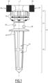
- a self-contained watering device 10 is shown in Figures 1 to 5 .
- the autonomous watering device 10 is intended to be connected to a watering installation, by being arranged in the ground of an area to be irrigated, for example within an agricultural plot or a garden.
- the device 10 is intended to be arranged between a water source not shown and irrigation means not shown, such as for example an oscillating sprinkler, a sprinkler, or even a garden hose.
- the autonomous watering device 10 comprises a valve 12, a regulator 14 and a humidity sensor 16, provided for measuring a humidity level of the soil in which the autonomous watering device is arranged.
- the autonomous watering device 10 is a single piece, that is to say that the valve 12, the regulator 14 and the humidity sensor 16 are assembled together so as to form a rigid assembly.
- the autonomous watering device 10 has a body 18, in which the valve, the regulator and the humidity sensor are formed.
- the body 18 is formed of several elements assembled together.
- the valve 12 comprises a water inlet pipe 20 and a water outlet pipe 22, which are respectively provided to be connected to the water source, and to the irrigation means by pipes not shown, and which are provided in the body 18.
- the water inlet 20 and water outlet 22 conduits each comprise a thread, denoted 24 and 26 respectively, which allow the connection of the conduits 20 and 22 to the water source and to the irrigation means by screwing the ends of the pipes.
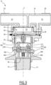
- the valve 12 comprises a control chamber 28, formed in the body 18, through which the water inlet pipe 20 is connected to the water outlet pipe 22.
- the control chamber 28 is in fluid communication on the one hand with the water inlet pipe 20 and on the other hand with the water outlet pipe 22.
- a downstream end 30 of the water inlet pipe 20 opens into the control chamber 28, and an upstream end 32 of the water outlet pipe 22 opens into the control chamber.
- a circulation of water through the valve 12, denoted C1 passes through the downstream end 30 of the water inlet pipe 20, through the control chamber 28, then through the upstream end 32 of the water outlet pipe 22.
- downstream end 30 of the water inlet pipe 20 is cylindrical, and opens onto the center of the control chamber 28, and the upstream end 32 of the water outlet pipe 22 is annular, and opens onto the periphery of the control chamber.
- Valve 12 is switchable between an open configuration, in which water circulation C1 is permitted, as shown in figures 2 And 5 , and a closed configuration, in which the water circulation C1 is interrupted, as shown in the figures 3 And 4 .
- the valve 12 comprises a first membrane 34, arranged in the control chamber 28, and which separates the control chamber into a first volume V1 and a second volume V2.
- first membrane 34 arranged in the control chamber 28, and which separates the control chamber into a first volume V1 and a second volume V2.
- the downstream end 30 of the water inlet pipe 20 and the upstream end 32 of the water outlet pipe 22 open into the first volume V1 of the control chamber.
- the water circulation C1 therefore passes through the first volume V1.
- the membrane 34 is movable relative to the body 18 between an open position, when the valve is in the open configuration, and a closed position, when the valve is in the closed configuration.
- the membrane 34 In the closed position, the membrane 34 is pressed against the downstream end 30 of the water inlet pipe 20 and against the upstream end 32 of the water outlet pipe 22, thus preventing the circulation of water C1.
- the first volume V1 has a zero volume.
- the membrane 34 In the open position, the membrane 34 is spaced from the ends 30 and 32, so as to allow the circulation of water C1 through the first volume V1, between the ends 30 and 32.
- the membrane 34 is elastically deformable, and its rest position is its closed position.
- rest position we mean the position that the membrane 34 takes by elastic return when it is not subjected to external forces other than atmospheric pressure. Thus, in the absence of external forces, the membrane tends to tilt from its open position to its closed position.
- the membrane 34 comprises a through-orifice 36, through which the first volume V1 and the second volume V2 are in fluid communication.
- the through-orifice 36 is in practice of small dimensions compared to the dimensions of the membrane 34.
- the area of the section of the through-orifice 36 is less than 5% of the area of the section of the upstream end 32 of the water outlet conduit 22.
- valve 12 comprises a bypass conduit 38, which connects the second volume V2 of the control chamber 28 to the water outlet conduit 22, so as to allow another circulation of water C2 between the water inlet conduit 20 and the water outlet conduit 22, via the first volume V1, the through-orifice 36, the second volume V2, then the bypass conduit 38.
- the bypass conduit 38 is of small dimensions compared to the dimensions of the water inlet conduit 20 and water outlet conduit 24. In practice, the area of the minimum section of the bypass conduit 38 is less than 5% of the area of the internal section of the conduits 20 and 22.
- the bypass conduit 38 comprises three sections 38A, 38B and 38C which respectively form an upstream section, an intermediate section and a downstream section of the bypass conduit.
- the upstream section 38A is in the form of a straight tube and passes through a wall 39 which delimits the control chamber 28.
- the wall 39 delimits the volume V2 downwards.
- the intermediate section 38B is in the form of a plate and extends along the wall 39, on its side opposite the control chamber 28.
- the downstream section 38C is in the form of a straight tube and extends, radially to a longitudinal axis Z of the regulator 14, on the outside of the intermediate section 38B, through a part of the body 18 in one piece with the wall 39 and through an end piece of the water outlet conduit.
- the area of the section of the through-orifice 36 is less than or equal to half the area of the section of the upstream section 38A of the bypass duct, and the area of the section of the upstream section 38A is itself less than the area of the section of the downstream section 38C of the bypass duct. Indeed, thanks to these proportions, a circulation of water from the water inlet duct 20 to the volume V2, via the through-orifice 36, is less easy than a circulation of water from the volume V2 to the water outlet duct 24, via the bypass duct 38.
- the flow rate of the water circulation C2 is low compared to the flow rate of the water circulation C1, for example 100 times lower, due to the small dimensions of the through orifice 36 and the bypass conduit 38.
- the regulator 14 is provided to selectively authorize, or interrupt, the circulation of water C2 passing through the bypass conduit 38.
- the circulation of water C2 causes negligible pressure losses between the volume V2 and the water outlet conduit 22.
- the pressure in the volume V2 is then identical to the pressure in the water outlet conduit 22, and lower than the pressure in the volume V1.
- the membrane 34 is thus maintained in the open position, and does not obstruct the circulation of water C1.
- the force exerted by the pressure difference between the first volume V1 and the second volume V2 is sufficient to deform the membrane 34 in the open position, against its elastic return in the closed position.
- the membrane 34 When the water circulation C2 is prevented by the regulator 14, then the membrane 34 is in the closed position, the first volume V1 has a zero volume and the valve 12 is in the closed configuration. Indeed, when the water circulation C2 is prevented, the water present in the second volume V2, which reaches the second volume via the through-orifice 36 of the membrane 34, cannot exit the second volume V2.
- the hydrostatic pressure present in the downstream end 30 of the water inlet pipe 20 is then identical to the hydrostatic pressure present in the second volume V2.
- the hydrostatic pressure present in the upstream end 32 of the water outlet pipe 22 is lower than the hydrostatic pressure present in the second volume V2, since the water outlet pipe 22 is not supplied with water.
- the force exerted on the membrane 34 on the side of the volume V2 is then greater than the force exerted on the membrane on the side of the downstream 30 and upstream 32 ends, since at the upstream end 32 of the water outlet conduit 22, the two sides of the membrane are exposed to different hydrostatic pressures, which leads to the membrane 34 tilting into the closed position. Furthermore, this tilting into the closed position is promoted by the return of the membrane to its rest position, by elastic return.
- the area of the surface of the membrane subjected to the action of the hydraulic pressure on the side of the second volume V2 which corresponds to the section of the control chamber 28 minus the section of the through-orifice 36, is greater than the area of the surface of the membrane subjected to the action of the hydraulic pressure on the side of the water inlet pipe 20, which corresponds to the section of the downstream end 30 of the water inlet pipe minus the section of the through-orifice.
- the water present in the second volume V2 then exerts a greater force on the membrane 34 than the water present in the downstream end 30 of the water inlet pipe 20, which tends to keep the membrane in the closed position.
- the regulator 14 is provided to authorize or interrupt the circulation of water C2 passing through the bypass conduit 38 depending on the state of the humidity sensor 16, more precisely depending on the humidity level of the soil measured by the humidity sensor.
- the regulator 14 comprises a second membrane 50, arranged in the bypass duct 38, in the example in the intermediate section 38B, so as to be movable, relative to the body 18, between a closed position, visible at figures 3 And 4 , in which the membrane obstructs the bypass conduit 38, at the junction between the upstream 38A and intermediate 38B sections, thus preventing the circulation of water C2, and an open position, visible at figures 2 And 5 , in which the membrane does not oppose the circulation of water C2.
- a second membrane 50 arranged in the bypass duct 38, in the example in the intermediate section 38B, so as to be movable, relative to the body 18, between a closed position, visible at figures 3 And 4 , in which the membrane obstructs the bypass conduit 38, at the junction between the upstream 38A and intermediate 38B sections, thus preventing the circulation of water C2, and an open position, visible at figures 2 And 5 , in which the membrane does not oppose the circulation of water C2.
- the membrane 50 is elastically deformable, and its rest position is its closed position.
- rest position we mean the position that the membrane 50 takes by elastic return when it is not subjected to external forces other than atmospheric pressure.
- the membrane 50 tends to tilt from its closed position to its open position.
- the regulator 14 comprises a pusher 52, a bistable tilting member 54, an opening actuator 56, a closing actuator 58 and a piston 60, which is movable in translation in the body 18 along the longitudinal axis Z of the regulator 14, being driven by the humidity sensor 16.
- the bistable tilting member 54 is a blade, mounted in the body 18, which has two stable positions, namely a closed position and a closed position.
- the blade 54 is therefore a bistable blade.
- the bistable blade 54 is made of a metallic material.
- the pusher 52 is mounted between the bistable blade 54 and the membrane 50, so as to switch by a translation between a closed position and an open position, according to the position of the bistable blade.
- the pusher 52 is movable in translation relative to the body 18.
- the pusher 52 is fixed on the one hand to the bistable blade 54, and on the other hand to the membrane 50, for example by gluing.
- the pusher drives the membrane 50 to the open position
- the bistable blade and the pusher tilt to the closed position then the pusher drives the membrane to the closed position.
- the deformation of the membrane 50 and the bistable blade 54, as well as the translation of the pusher 52, are carried out along the Z axis.
- the pusher 52 is not fixed to the bistable blade 54 and to the membrane 50.
- the bistable blade tilts to the open position, the hydrostatic pressure applied to the membrane 50 is then sufficient to cause the membrane 50 and the pusher 52 to tilt to the open position.
- the bistable blade 54 is sized so that, when the membrane 50, the pusher 52 and the bistable blade are in the closed position, the force exerted on the membrane 50, at the upstream section 38A, by the hydrostatic pressure present in the second volume V2, and transmitted to the bistable blade via the pusher 52, is not sufficient to cause the bistable blade to tilt into the open position.
- the pusher 52 is particularly advantageous, because it makes it possible to control the position of the membrane 50 from the position of the bistable blade 54 while positioning the bistable blade at a distance from the membrane, which facilitates the operation of the bistable blade by the opening 56 and closing 58 actuators.
- the opening actuator 56 comprises an opening head 57 which comprises an end 62.
- H1 denotes the distance between the end 62 and the membrane 50, and H2 the distance between the end 62 and the piston 60.
- the closing actuator 58 comprises a closing head 59 which comprises an end 64, and H3 denotes the distance between the end 64 and the membrane 50, and H4 the distance between the end 64 and the piston 60.
- the distances H1, H2, H3 and H4 are measured parallel to the Z axis.
- the opening head 57 and the closing head 59 are integral in translation with the piston 60, so that a movement of the piston along the Z axis causes an identical movement of the opening and closing heads.
- the regulator 14 is configured so that the opening actuator 56, and more precisely its opening head 57, switches the bistable blade 54 to the opening position when the distance H1 reaches a predetermined threshold value, called the “opening threshold”, corresponding to an opening position of the piston 60.
- the regulator 14 is configured so that the closing actuator 58, and more precisely its closing head 59, switches the bistable blade 54 to the closing position when the distance H3 reaches a predetermined threshold value, called “closing threshold”, corresponding to a closing position of the piston.
- the opening head 57 of the opening actuator 56 extends through the bistable blade 54, and its collar-shaped end 62 is provided to pull on the bistable blade in order to cause it to tilt from its closed position to its open position when the distance H1 increases until reaching the opening threshold.
- the end 64 of the closing head 59 which is pointed, is provided to push on the bistable blade in order to cause it to tilt into the closing position when the distance H3 decreases until reaching the closing threshold.
- the distances H1 and H3 are determined by the geometry of the constituent elements of the regulator 14, in particular by the position of the bistable blade 54 within the body 18, and are therefore intrinsic properties of the autonomous watering device 10, which depend on its design.
- the distances H2 and H4 are adjustable, which makes it possible to adjust the opening position of the piston 60 corresponding to the opening threshold and to adjust the closing position of the piston corresponding to the closing threshold.
- the opening actuator 56 comprises an adjustment device 66, which makes it possible to adjust the distance H2.
- the opening head 57 of the opening actuator 56 is screwed onto the piston 60 by means of a tapping 57A provided on the opening head and a thread 60A provided on a rod 60B which is part of the piston 60.
- the adjustment device 66 is an adjustment wheel, which is held on the body 18 so as to be only movable in rotation relative to the body, which extends partially outside the body 18 through a window 18A and which allows a user to screw or unscrew the opening head 57 of the opening actuator 56 relative to the piston 60, thereby varying the distance H2.
- the opening head 57 extends through a central opening 66A formed in the adjustment wheel 66, so as to be movable in translation relative to the adjustment wheel.
- the opening actuator 56 comprises a key 66B, so that a rotation of the adjustment wheel causes a rotation of the opening head.
- the opening actuator 56 is therefore accessible from outside the autonomous watering device 10, via the adjustment wheel 66.
- the closing head 59 of the closing actuator 58 is screwed onto the piston 60 by means of a tapping 59A provided on the closing head and a thread 60C provided on a rod 60D which is part of the piston 60.
- the closing actuator comprises an adjustment device 68, which is in the example an adjustment wheel which makes it possible to adjust the distance H4, and which functions like the adjustment device 66.
- the adjustment wheel 68 thus extends partially outside the body 18 through a window 18B
- the closing head 59 extends through a central opening 68A provided in the adjustment wheel 68 and the closing actuator comprises a key 68B so that a rotation of the adjustment wheel causes a rotation of the closing head.
- the humidity sensor 16 is in practice arranged in the soil whose humidity level is to be measured.
- the humidity sensor 16 comprises a quantity 70 of hygroscopic material, that is to say that its humidity level varies according to the humidity level of the soil surrounding the material.
- the volume of the quantity 70 varies according to the humidity level of its material.
- the material of quantity 70 is for example wood, or even clay.
- the material of the quantity 70 is in practice disposed in the body 18, and the body has openings 72, which allow the material to be in direct contact with the surrounding soil.
- the quantity 70 is held in the body 18 by a retaining element 73, so as to prevent its dispersion through the openings 72.
- the retaining element 73 is provided to be permeable to moisture, or to be itself hygroscopic, so as to allow the moisture content of the quantity 70 to equilibrate with the moisture content of the soil surrounding the humidity sensor.
- the retaining element 73 does not form a tight barrier between the quantity 70 and the soil surrounding the quantity 70.
- the retaining element 73 is a mesh or a net, or else comprises both a mesh and a net.
- the quantity 70 is in contact with the piston 60.
- the quantity 70 expands, it pushes on the piston 60, upwards in the configuration of use of the autonomous watering device 10, which causes a movement of the piston along the Z axis, in the direction of the control chamber 28.
- the quantity 70 can only expand in the direction of the piston 60, because the quantity is held moreover by the body 18, which is rigid, and by the retaining element 73 which prevents the quantity 70 from extending into the openings 72.
- the piston 60 is pushed back by an elastic return member 74 in the direction of the quantity, so as to remain in contact with the quantity.
- the elastic return member 74 is a helical spring.
- the spring 74 bears on the adjustment device 68 to push back the piston 60.
- the spring 74 bears directly on the body 18.
- the spring 74 is provided so that the restoring force exerted on the piston 60 does not oppose the movement of the piston when the quantity 70 expands.
- valve 12 is in the open configuration, and the autonomous watering device 10 is in a pre-closing configuration, i.e. before the valve 12 switches to the closed configuration.
- the water circulations C1 and C2 are permitted, the membranes 34 and 50 as well as the bistable blade 54 being in the open position.
- the piston 60 is very close to its position corresponding to the closing threshold, so that the closing head 59 of the closing actuator 58 is in contact with the bistable blade 54, but without exerting a force on the bistable blade sufficient to cause it to tilt from its open position to its closed position.
- the end 64 of the closing head 59 is in contact with the bistable blade, but does not push on the blade.
- the humidity level of the soil surrounding the autonomous watering device is increasing, causing the material to expand by the amount 70.
- the valve 12 is in the closed configuration, and the autonomous watering device 10 is in a configuration after closing.
- the passage from the configuration before closing of the figure 2 to the configuration after closing the figure 3 is carried out when the piston 60 reaches its position corresponding to the closing threshold, being pushed by the expansion of the material 70, so that the closing head 59 causes the bistable blade 54 to tilt into the closing position, in the example by pushing on the bistable blade via its end 64.
- the tilting of the bistable blade into the closing position causes the membrane 50 to tilt into the closing position, which interrupts the circulation of water C2, thus driving the membrane 34 into the closing position and thus interrupting the circulation of water C1.
- valve 12 when the valve 12 is in the closed configuration, further expansion of the material by the quantity 70 causes the piston 60 to move beyond from its position corresponding to the closing threshold is possible, because following the tilting of the bistable blade 54, the end 64 of the closing head 59 is located at a distance from the bistable blade.
- a decrease in soil moisture causes a displacement of the piston 60 under the effect of the spring 74, until reaching the configuration of the figure 4 , in which the valve 12 is still in the closed configuration, and in which the autonomous watering device 10 is in a pre-opening configuration, i.e. before the valve 12 switches to the open configuration.
- the piston 60 is very close to its position corresponding to the opening threshold, such that the opening head 57 of the opening actuator 56 is in contact with the bistable blade 54, but without exerting a force on the bistable blade sufficient to cause it to switch.
- the end 62 of the opening head is in contact with the bistable blade, but does not pull on the blade.
- the moisture content of the soil surrounding the autonomous watering device is decreasing, causing the material to contract by the amount 70.
- the valve 12 is in the open configuration, and the autonomous watering device 10 is in a configuration after opening.
- the passage from the configuration before opening of the figure 4 to the configuration after opening the figure 5 is carried out when the piston 60 reaches its position corresponding to the opening threshold, being pushed by the spring 74, so that the opening head 57 causes the bistable blade to tilt into the opening position, in the example by pulling on the bistable blade via its end 62.
- the tilting of the bistable blade into the opening position causes the membrane 50 to tilt into the opening position, which allows the water circulation C2 to resume, thus driving the membrane 34 into the opening position and thus allowing the water circulation C1 to resume.
- valve 12 when the valve 12 is in the open configuration, an additional contraction of the material by the quantity 70 causing a movement of the piston 60 under the effect of the spring 74 beyond its position corresponding to the opening threshold is possible, because following the tilting of the bistable blade 54, the end 62 of the opening head 57 is located at a distance from the bistable blade.
- the stroke of the piston 60 between its position corresponding to the opening threshold, as at figure 5 , and its position corresponding to the closing threshold, as at the figure 3 is between 0.5 mm and 4 mm, preferably equal to 1 mm.
- This stroke is determined by a maximum humidity rate of the material of the quantity 70, and therefore of the soil, which causes the valve 12 to switch to the closed configuration when it is reached, and by a minimum moisture content of the material of the quantity 70, which causes the valve to switch to the open configuration when it is reached.
- These two moisture contents define a soil moisture range in which the autonomous watering device 10 maintains the soil moisture content by autonomously opening and closing the valve 12. This moisture range is, for example, between 10% and 35%.
- the closing threshold causing the valve 12 to switch to the closed configuration is distinct from the opening threshold causing the valve to switch to the open configuration.
- the presence of two distinct thresholds makes it possible to optimize the irrigation of the area to be irrigated, by finely controlling the soil moisture range in which the soil moisture level is maintained by the autonomous watering device 10, since the closing threshold corresponds to a maximum moisture level and the opening threshold corresponds to a minimum moisture level. Such control is more effective for irrigating an area than other existing systems, for which there is no differentiation between the opening threshold and the closing threshold of the valve.
- the soil moisture range in which the autonomous watering device 10 maintains the soil of the area to be irrigated is varied.
- This moisture range is then particularly simple to adapt, depending on the nature of the plantations to be irrigated by the autonomous watering device 10. For example, for certain plantations requiring a slightly varying humidity level, the soil moisture range is reduced, corresponding to a short stroke of the piston 60. In such an example, the valve 12 is caused to frequently switch between its open and closed configurations. Conversely, for other plantations that tolerate large variations in soil moisture, the soil moisture range is increased, corresponding to a higher stroke of the piston 60. In such an example, the valve 12 is caused to switch less frequently between its open and closed configurations.
- the bistable blade 54 is particularly interesting. Indeed, thanks to the presence of the bistable blade, the opening and closing of the valve 12 are sharp, that is to say immediate, and are therefore not progressive or subject to oscillations. Such a sharp opening and closing of the valve is particularly advantageous so that the irrigation of the area to be irrigated is homogeneous. Conversely, a progressive or oscillating closing and opening of the valve would lead to supplying the irrigation means with a flow of water whose flow rate varies gradually or is interrupted.
- the irrigation means are for example a sprinkler, or an oscillating sprinkler
- the gradual decrease and increase in flow rate lead to watering the area close to the irrigation means with greater quantities of water than the areas far from the irrigation means, because when the valve is closing and opening, the areas far from the irrigation means do not receive water, due to the reduced flow rate.
- the irrigation of the plantations would not be homogeneous, which is negative.
- the tilting member 54 is not a bistable tilting member, but a progressive one.
- the opening and closing of the valve 12 are progressive.
- Such a variant is suitable, for example, when the irrigation means are a drip system, which operates with a low flow rate.
- the opening head 57 of the opening actuator 56 is configured to push on the bistable blade 54 and the closing head 59 of the closing actuator 58 is configured to pull on the bistable blade 54.
- the regulator 14 does not include a membrane 50, and the pusher 52 directly obstructs the circulation of water C2, for example at the level of the bypass conduit 38.
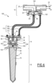
- a second embodiment of a self-contained watering device 100 In the second embodiment, elements similar to those of the first embodiment bear the same references and operate in the same way. If a reference is used in the description of the second embodiment without being reproduced on the figure 6 , it corresponds to the part or piece bearing the same reference in the first embodiment. In the following, the differences between the second embodiment and the first embodiment are mainly described.
- the autonomous watering device 100 is not rigid and in one piece.
- the autonomous watering device 100 has a first body 102, in which the valve 12 is formed, and a second body 104, distinct from the first body 102, in which the regulator 14 and the humidity sensor 16 are formed.
- the first body 102 and the second body 104 are each formed of several elements assembled together, so as to form two distinct rigid assemblies.
- the first body 102 and the second body 104 are connected together by a first pipe 106 and by a second pipe 108.
- the regulator 14 comprises a bypass circuit 110, in which the membrane 50 is movable.
- the membrane 50 prevents water from circulating in the bypass circuit when it is in the closed position, and allows water to circulate in the bypass circuit when it is in the open position.
- the first pipe 106 connects the second volume V2 of the control chamber 28 to the bypass circuit 110, and the second pipe 108 connects the bypass circuit 110 to the water outlet pipe 22.
- the first pipe 106, the bypass circuit 110 and the second pipe 108 together form a bypass conduit 112 of the valve 12, which functions like the bypass conduit 38 of the first embodiment. It is then understood that in the second embodiment, the water circulation C2 connects the water inlet conduit 20 and the water outlet conduit 22 via the first volume V1, the through orifice 36, the second volume V2, then the bypass conduit 112.
- the operation of the autonomous watering device 100 is therefore identical to the operation of the autonomous watering device 10 of the first embodiment.
- the autonomous watering device 100 is particularly advantageous for optimizing the watering of the area to be irrigated, because it allows the sensor 16 to be moved away from the valve 12.
- the valve 12 is located at the edge of an area to be irrigated, close to the irrigation means, while the sensor 16 and the regulator 14 are located in the center of the area to be irrigated, which makes it possible to measure a soil moisture level more representative of the area to be irrigated, compared to a measurement taken at the edge of the area to be irrigated.
- Relocating the sensor 16 from the valve 12 is also practical for moving the valve 12 away from the area to be irrigated, for example when the valve is connected to the irrigation means by large pipes.
Landscapes
- Engineering & Computer Science (AREA)
- General Engineering & Computer Science (AREA)
- Life Sciences & Earth Sciences (AREA)
- Water Supply & Treatment (AREA)
- Environmental Sciences (AREA)
- Mechanical Engineering (AREA)
- Soil Sciences (AREA)
- Soil Working Implements (AREA)
- Fluid-Driven Valves (AREA)
- Mechanically-Actuated Valves (AREA)
- Nozzles (AREA)
Claims (10)
- Autonome Bewässerungsvorrichtung (10; 100) bestehend aus:- einem Ventil (12), umschaltbar zwischen einer offenen und einer geschlossenen Konfiguration, mit einem Wasserzulaufrohr (20), einem Wasserablaufrohr (22), einer Steuerkammer (28), durch die die Wasserzulauf- und -ablaufrohre verbunden sind, und einer ersten Membran (34), die in der Steuerkammer angeordnet und zwischen einer geschlossenen Position beweglich ist, wenn sich das Ventil in einer geschlossenen Konfiguration befindet, in der ein Wasserfluss (C1) durch das Ventil (12) verhindert wird, und in einer offenen Position, wenn sich das Ventil in einer offenen Konfiguration befindet, in der ein Wasserfluss (C1) durch das Ventil nicht verhindert wird;- einem Regler (14), der eine Kippvorrichtung (54) umfasst, die so betätigt werden kann, dass das Ventil zwischen seiner offenen und geschlossenen Konfiguration kippt, indem die erste Membran (34) zwischen ihrer offenen und geschlossenen Position bewegt wird; und- einem Feuchtigkeitssensor (16), der so konfiguriert ist, dass er in einem Boden platziert wird und den Regler (14) entsprechend einem Bodenfeuchtigkeitsgehalt betätigt,dadurch gekennzeichnet, dass:- der Regler einen Öffnungsantrieb (56) aufweist, der einen Öffnungskopf (57) umfasst, der so konfiguriert ist, dass er das Kippelement (54) betätigt, um zu bewirken, dass sich die erste Membran von ihrer geschlossenen Position in ihre offene Position bewegt, wenn ein vom Feuchtigkeitssensor (16) gemessener Bodenfeuchtigkeitsgehalt einen minimalen Feuchtigkeitsgehalt erreicht;- der Regler (14) einen Schließantrieb (58) aufweist, der einen Schließkopf (59) umfasst, der so konfiguriert ist, dass er das Kippelement (54) betätigt, um zu bewirken, dass sich die erste Membran von ihrer offenen Position in ihre geschlossene Position bewegt, wenn ein vom Feuchtigkeitssensor gemessener Bodenfeuchtigkeitsgehalt einen maximalen Feuchtigkeitsgehalt erreicht; und- der Öffnungsantrieb und der Schließantrieb voneinander getrennt sind.
- Autonome Bewässerungsvorrichtung (10; 100) nach Anspruch 1, wobei der Feuchtigkeitssensor (16) eine Menge (70) eines hygroskopischen Materials umfasst, deren Volumen entsprechend dem Bodenfeuchtigkeitsgehalt variiert, wobei der Regler (14) einen Kolben (60) umfasst, der durch den Antrieb durch das Material bewegt werden kann, und wobei die Öffnungs- (57) und Schließköpfe (59) durch den Kolben angetrieben werden.
- Autonome Bewässerungsvorrichtung (10; 100) nach einem der Ansprüche 1 und 2, wobei der Öffnungsantrieb (56) eine Einstellvorrichtung (66) umfasst, die so konfiguriert ist, dass sie einen von dem Feuchtigkeitssensor (16) erfassten minimalen Feuchtigkeitsgehalt einstellt und bewirkt, dass sich die erste Membran (34) von ihrer geschlossenen Position in ihre offene Position bewegt, und wobei der Schließantrieb (58) eine Einstellvorrichtung (68) umfasst, die so konfiguriert ist, dass sie einen von dem Feuchtigkeitssensor erfassten maximalen Feuchtigkeitsgehalt einstellt und bewirkt, dass sich die erste Membran von ihrer offenen Position in ihre geschlossenen Position bewegt.
- Autonome Bewässerungsvorrichtung (10; 100) nach Anspruch 3, wobei die Einstellvorrichtung (56) des Öffnungsantriebs (56) und die Einstellvorrichtung (68) des Schließantriebs (58) von der Außenseite eines Körpers (18) der autonomen Bewässerungseinrichtung (10; 100) zugänglich sind.
- Autonome Bewässerungsvorrichtung (10; 100) nach einem der Ansprüche 3 und 4, in Kombination mit Anspruch 2 betrachtet, wobei der Öffnungskopf (57) und der Schließkopf (59) auf den Kolben (60) aufgeschraubt sind, wobei die Einstellvorrichtung (66) des Öffnungsantriebs (56) so konfiguriert ist, dass sie den Öffnungskopf in Bezug auf den Kolben an- oder abschraubt, sodass ein Abstand (H2) zwischen einem Ende (62) des Öffnungskopfes und dem Kolben eingestellt wird, und wobei die Einstellvorrichtung (68) des Schließantriebs (58) so konfiguriert ist, dass sie den Schließkopf in Bezug auf den Kolben an- oder abschraubt, sodass ein Abstand (H4) zwischen einem Ende (64) des Schließkopfes und dem Kolben eingestellt wird.
- Autonome Bewässerungsvorrichtung (10; 100) nach einem der vorhergehenden Ansprüche, wobei das Kippelement (54) bistabil ist.
- Autonome Bewässerungsvorrichtung (10; 100) nach Anspruch 6, wobei das Kippelement (54) eine bistabile Klinge ist, wobei ein erster Kopf zwischen dem Öffnungskopf (57) und dem Schließkopf (59) so konfiguriert ist, dass er an der bistabilen Klinge zieht, um das Ventil (12) zwischen seiner offenen und geschlossenen Konfiguration kippen zu lassen, und wobei ein zweiter Kopf zwischen dem Öffnungskopf und dem Schließkopf so konfiguriert ist, dass er auf die bistabile Klinge drückt, um das Ventil zwischen seiner geschlossenen und offenen Konfiguration kippen zu lassen.
- Autonome Bewässerungsvorrichtung (10; 100) nach einem der vorhergehenden Ansprüche, wobei das Ventil (12) eine Bypassleitung (38; 112) umfasst, die die Steuerkammer (28) mit dem Wasserablaufrohr (22) verbindet, wobei sich das Ventil in einer offenen Konfiguration befindet, wenn ein Wasserfluss (C2) durch die Bypassleitung zulässig ist, wobei sich das Ventil in einer geschlossenen Konfiguration befindet, wenn der Wasserfluss (C2) durch die Bypassleitung unterbrochen wird, und wobei das Kippelement (54) so konfiguriert ist, dass es selektiv den Wasserfluss (C2) durch die Bypassleitung zulässt oder unterbricht.
- Autonome Bewässerungsvorrichtung (10; 100) nach Anspruch 8, wobei der Regler (14) eine zweite Membran (50) umfasst, die in der Bypassleitung (38; 112) angeordnet ist und zwischen einer Öffnungsstellung, wobei die zweite Membran dem Wasserfluss (C2) durch die Bypassleitung nicht entgegensteht, und einer geschlossenen Stellung beweglich ist, wobei die zweite Membran dem Wasserfluss durch die Bypassleitung entgegenwirkt, und wobei das Kippen des Kippelements (54) bewirkt, dass sich die zweite Membran (50) zwischen ihrer geöffneten und geschlossenen Position bewegt.
- Autonome Bewässerungsvorrichtung (10; 100) nach Anspruch 9, wobei der Regler (14) einen Schieber (52) umfasst, der zwischen dem Kippelement (54) und der zweiten Membran (50) montiert und einerseits an dem Kippelement und andererseits an der zweiten Membran befestigt ist.
Applications Claiming Priority (1)
| Application Number | Priority Date | Filing Date | Title |
|---|---|---|---|
| FR2113498A FR3130114B1 (fr) | 2021-12-14 | 2021-12-14 | Dispositif d’arrosage autonome |
Publications (3)
| Publication Number | Publication Date |
|---|---|
| EP4197316A1 EP4197316A1 (de) | 2023-06-21 |
| EP4197316B1 true EP4197316B1 (de) | 2024-10-30 |
| EP4197316C0 EP4197316C0 (de) | 2024-10-30 |
Family
ID=80446626
Family Applications (1)
| Application Number | Title | Priority Date | Filing Date |
|---|---|---|---|
| EP22213245.8A Active EP4197316B1 (de) | 2021-12-14 | 2022-12-13 | Autonome bewässerungsvorrichtung |
Country Status (3)
| Country | Link |
|---|---|
| EP (1) | EP4197316B1 (de) |
| ES (1) | ES3000658T3 (de) |
| FR (1) | FR3130114B1 (de) |
Families Citing this family (1)
| Publication number | Priority date | Publication date | Assignee | Title |
|---|---|---|---|---|
| CN118716172B (zh) * | 2024-07-12 | 2025-12-12 | 浙江省柑橘研究所 | 一种果树节水灌溉用水定额配给系统 |
Family Cites Families (3)
| Publication number | Priority date | Publication date | Assignee | Title |
|---|---|---|---|---|
| US5941501A (en) * | 1996-09-06 | 1999-08-24 | Xerox Corporation | Passively addressable cantilever valves |
| US20180328513A1 (en) | 2015-11-13 | 2018-11-15 | Rain Bird Corporation | Moisture sensing valves and devices |
| ES3034393T3 (en) * | 2019-03-27 | 2025-08-18 | Ofip Ltd | Device for controlling fluid flow |
-
2021
- 2021-12-14 FR FR2113498A patent/FR3130114B1/fr active Active
-
2022
- 2022-12-13 ES ES22213245T patent/ES3000658T3/es active Active
- 2022-12-13 EP EP22213245.8A patent/EP4197316B1/de active Active
Also Published As
| Publication number | Publication date |
|---|---|
| FR3130114B1 (fr) | 2023-12-22 |
| ES3000658T3 (en) | 2025-03-03 |
| FR3130114A1 (fr) | 2023-06-16 |
| EP4197316C0 (de) | 2024-10-30 |
| EP4197316A1 (de) | 2023-06-21 |
Similar Documents
| Publication | Publication Date | Title |
|---|---|---|
| FR2539203A1 (fr) | Valve a reglage prealable de debit, notamment pour installations de chauffage a eau chaude | |
| FR2690494A1 (fr) | Systeme de valve de regulation de pression d'huile pour transmissions hydrostatiques | |
| EP2480774B1 (de) | Vorrichtung zum dosieren von kraftstoff mit verbesserter regelungseinrichtung | |
| EP4197316B1 (de) | Autonome bewässerungsvorrichtung | |
| EP2964933A1 (de) | Kompakte dosierungsvorrichtung für einen injektor mit zwei brennstoffkreisläufen für eine flugzeugturbomaschine | |
| WO1987004537A1 (fr) | Regulateur de pression avec capteur integre | |
| EP0070778B1 (de) | Steuervorrichtung eines Sicherheitsventils | |
| EP0116247B1 (de) | Sicherheitsventil mit integrierter Pilotsteuerung | |
| EP0089881B1 (de) | Druckluftspareinrichtung | |
| FR2555700A1 (fr) | Soupape de pression | |
| FR2468775A1 (fr) | Distributeur hydraulique | |
| FR2468287A1 (fr) | Dispositif elevateur hydraulique pour outils, notamment atteles a des tracteurs | |
| EP3106957B1 (de) | Druckregler und entsprechendes sprühsystem | |
| FR2618868A1 (fr) | Dispositif formant detendeur de regulation automatique de pression d'un fluide gazeux | |
| EP0754914B1 (de) | Einspritzvorrichtung für atmosphärische Gasbrenner von Heizgeräten, insbesondere des Infrarottyps | |
| EP1937983B1 (de) | Ventil mit gedämpftem öffnungssystem | |
| FR2500186A1 (fr) | Vanne regulatrice de pression, notamment pour appareil d'arrosage | |
| FR2508566A1 (fr) | Distributeur de commande de verin | |
| EP0924465B1 (de) | Wassergesteuerter Heisswassererzeuger | |
| BE537652A (de) | ||
| CH596486A5 (en) | Fluid pressure control regulator | |
| FR2644868A1 (fr) | Soupape autostable | |
| EP0936386B1 (de) | Verfahren und Vorrichtung zur Steuerung der Überbrückungskupplung eines Drehmomentenwandlers | |
| FR2834084A1 (fr) | Regulateur automatique de debit de fluide d'un conduit aller d'un circuit de fluide | |
| WO2020115195A1 (fr) | Cartouche thermostatique pour robinet mitigeur |
Legal Events
| Date | Code | Title | Description |
|---|---|---|---|
| PUAI | Public reference made under article 153(3) epc to a published international application that has entered the european phase |
Free format text: ORIGINAL CODE: 0009012 |
|
| STAA | Information on the status of an ep patent application or granted ep patent |
Free format text: STATUS: THE APPLICATION HAS BEEN PUBLISHED |
|
| AK | Designated contracting states |
Kind code of ref document: A1 Designated state(s): AL AT BE BG CH CY CZ DE DK EE ES FI FR GB GR HR HU IE IS IT LI LT LU LV MC ME MK MT NL NO PL PT RO RS SE SI SK SM TR |
|
| STAA | Information on the status of an ep patent application or granted ep patent |
Free format text: STATUS: REQUEST FOR EXAMINATION WAS MADE |
|
| 17P | Request for examination filed |
Effective date: 20231123 |
|
| RBV | Designated contracting states (corrected) |
Designated state(s): AL AT BE BG CH CY CZ DE DK EE ES FI FR GB GR HR HU IE IS IT LI LT LU LV MC ME MK MT NL NO PL PT RO RS SE SI SK SM TR |
|
| RIC1 | Information provided on ipc code assigned before grant |
Ipc: F16K 31/385 20060101ALI20240326BHEP Ipc: F16K 31/00 20060101ALI20240326BHEP Ipc: A01G 27/00 20060101ALI20240326BHEP Ipc: A01G 25/16 20060101AFI20240326BHEP |
|
| GRAP | Despatch of communication of intention to grant a patent |
Free format text: ORIGINAL CODE: EPIDOSNIGR1 |
|
| STAA | Information on the status of an ep patent application or granted ep patent |
Free format text: STATUS: GRANT OF PATENT IS INTENDED |
|
| INTG | Intention to grant announced |
Effective date: 20240523 |
|
| GRAS | Grant fee paid |
Free format text: ORIGINAL CODE: EPIDOSNIGR3 |
|
| GRAA | (expected) grant |
Free format text: ORIGINAL CODE: 0009210 |
|
| STAA | Information on the status of an ep patent application or granted ep patent |
Free format text: STATUS: THE PATENT HAS BEEN GRANTED |
|
| AK | Designated contracting states |
Kind code of ref document: B1 Designated state(s): AL AT BE BG CH CY CZ DE DK EE ES FI FR GB GR HR HU IE IS IT LI LT LU LV MC ME MK MT NL NO PL PT RO RS SE SI SK SM TR |
|
| REG | Reference to a national code |
Ref country code: GB Ref legal event code: FG4D Free format text: NOT ENGLISH |
|
| REG | Reference to a national code |
Ref country code: CH Ref legal event code: EP |
|
| REG | Reference to a national code |
Ref country code: IE Ref legal event code: FG4D Free format text: LANGUAGE OF EP DOCUMENT: FRENCH |
|
| REG | Reference to a national code |
Ref country code: DE Ref legal event code: R096 Ref document number: 602022007244 Country of ref document: DE |
|
| U01 | Request for unitary effect filed |
Effective date: 20241128 |
|
| U07 | Unitary effect registered |
Designated state(s): AT BE BG DE DK EE FI FR IT LT LU LV MT NL PT RO SE SI Effective date: 20241210 |
|
| U20 | Renewal fee for the european patent with unitary effect paid |
Year of fee payment: 3 Effective date: 20241209 |
|
| REG | Reference to a national code |
Ref country code: ES Ref legal event code: FG2A Ref document number: 3000658 Country of ref document: ES Kind code of ref document: T3 Effective date: 20250303 |
|
| RAP4 | Party data changed (patent owner data changed or rights of a patent transferred) |
Owner name: IRRIGIO |
|
| U1H | Name or address of the proprietor changed after the registration of the unitary effect |
Owner name: IRRIGIO; FR |
|
| PG25 | Lapsed in a contracting state [announced via postgrant information from national office to epo] |
Ref country code: IS Free format text: LAPSE BECAUSE OF FAILURE TO SUBMIT A TRANSLATION OF THE DESCRIPTION OR TO PAY THE FEE WITHIN THE PRESCRIBED TIME-LIMIT Effective date: 20250228 Ref country code: HR Free format text: LAPSE BECAUSE OF FAILURE TO SUBMIT A TRANSLATION OF THE DESCRIPTION OR TO PAY THE FEE WITHIN THE PRESCRIBED TIME-LIMIT Effective date: 20241030 |
|
| PGFP | Annual fee paid to national office [announced via postgrant information from national office to epo] |
Ref country code: ES Payment date: 20250107 Year of fee payment: 3 |
|
| PG25 | Lapsed in a contracting state [announced via postgrant information from national office to epo] |
Ref country code: NO Free format text: LAPSE BECAUSE OF FAILURE TO SUBMIT A TRANSLATION OF THE DESCRIPTION OR TO PAY THE FEE WITHIN THE PRESCRIBED TIME-LIMIT Effective date: 20250130 |
|
| PG25 | Lapsed in a contracting state [announced via postgrant information from national office to epo] |
Ref country code: GR Free format text: LAPSE BECAUSE OF FAILURE TO SUBMIT A TRANSLATION OF THE DESCRIPTION OR TO PAY THE FEE WITHIN THE PRESCRIBED TIME-LIMIT Effective date: 20250131 |
|
| PG25 | Lapsed in a contracting state [announced via postgrant information from national office to epo] |
Ref country code: PL Free format text: LAPSE BECAUSE OF FAILURE TO SUBMIT A TRANSLATION OF THE DESCRIPTION OR TO PAY THE FEE WITHIN THE PRESCRIBED TIME-LIMIT Effective date: 20241030 |
|
| PG25 | Lapsed in a contracting state [announced via postgrant information from national office to epo] |
Ref country code: RS Free format text: LAPSE BECAUSE OF FAILURE TO SUBMIT A TRANSLATION OF THE DESCRIPTION OR TO PAY THE FEE WITHIN THE PRESCRIBED TIME-LIMIT Effective date: 20250130 |
|
| PG25 | Lapsed in a contracting state [announced via postgrant information from national office to epo] |
Ref country code: SM Free format text: LAPSE BECAUSE OF FAILURE TO SUBMIT A TRANSLATION OF THE DESCRIPTION OR TO PAY THE FEE WITHIN THE PRESCRIBED TIME-LIMIT Effective date: 20241030 |
|
| PG25 | Lapsed in a contracting state [announced via postgrant information from national office to epo] |
Ref country code: MC Free format text: LAPSE BECAUSE OF FAILURE TO SUBMIT A TRANSLATION OF THE DESCRIPTION OR TO PAY THE FEE WITHIN THE PRESCRIBED TIME-LIMIT Effective date: 20241030 |
|
| PG25 | Lapsed in a contracting state [announced via postgrant information from national office to epo] |
Ref country code: SK Free format text: LAPSE BECAUSE OF FAILURE TO SUBMIT A TRANSLATION OF THE DESCRIPTION OR TO PAY THE FEE WITHIN THE PRESCRIBED TIME-LIMIT Effective date: 20241030 |
|
| PG25 | Lapsed in a contracting state [announced via postgrant information from national office to epo] |
Ref country code: CZ Free format text: LAPSE BECAUSE OF FAILURE TO SUBMIT A TRANSLATION OF THE DESCRIPTION OR TO PAY THE FEE WITHIN THE PRESCRIBED TIME-LIMIT Effective date: 20241030 |
|
| PLBE | No opposition filed within time limit |
Free format text: ORIGINAL CODE: 0009261 |
|
| STAA | Information on the status of an ep patent application or granted ep patent |
Free format text: STATUS: NO OPPOSITION FILED WITHIN TIME LIMIT |
|
| 26N | No opposition filed |
Effective date: 20250731 |
|
| PG25 | Lapsed in a contracting state [announced via postgrant information from national office to epo] |
Ref country code: IE Free format text: LAPSE BECAUSE OF NON-PAYMENT OF DUE FEES Effective date: 20241213 |
|
| U20 | Renewal fee for the european patent with unitary effect paid |
Year of fee payment: 4 Effective date: 20251114 |