EP0936386B1 - Verfahren und Vorrichtung zur Steuerung der Überbrückungskupplung eines Drehmomentenwandlers - Google Patents
Verfahren und Vorrichtung zur Steuerung der Überbrückungskupplung eines Drehmomentenwandlers Download PDFInfo
- Publication number
- EP0936386B1 EP0936386B1 EP19990400320 EP99400320A EP0936386B1 EP 0936386 B1 EP0936386 B1 EP 0936386B1 EP 19990400320 EP19990400320 EP 19990400320 EP 99400320 A EP99400320 A EP 99400320A EP 0936386 B1 EP0936386 B1 EP 0936386B1
- Authority
- EP
- European Patent Office
- Prior art keywords
- pressure
- bridging
- valve
- piloting
- converter
- Prior art date
- Legal status (The legal status is an assumption and is not a legal conclusion. Google has not performed a legal analysis and makes no representation as to the accuracy of the status listed.)
- Expired - Lifetime
Links
- 238000000034 method Methods 0.000 title claims description 13
- 230000005540 biological transmission Effects 0.000 claims description 12
- 238000006073 displacement reaction Methods 0.000 claims description 10
- 230000000694 effects Effects 0.000 claims description 7
- 230000001105 regulatory effect Effects 0.000 claims description 4
- 230000001276 controlling effect Effects 0.000 claims description 3
- 230000001970 hydrokinetic effect Effects 0.000 claims description 3
- 238000012886 linear function Methods 0.000 claims description 2
- 230000008034 disappearance Effects 0.000 claims 1
- 238000011144 upstream manufacturing Methods 0.000 claims 1
- 238000010586 diagram Methods 0.000 description 3
- 238000005461 lubrication Methods 0.000 description 3
- 230000009286 beneficial effect Effects 0.000 description 2
- 238000004891 communication Methods 0.000 description 2
- 238000001914 filtration Methods 0.000 description 2
- 239000012530 fluid Substances 0.000 description 2
- 239000006096 absorbing agent Substances 0.000 description 1
- 238000006243 chemical reaction Methods 0.000 description 1
- 239000006185 dispersion Substances 0.000 description 1
- 230000035939 shock Effects 0.000 description 1
- 230000007704 transition Effects 0.000 description 1
Images

Classifications
-
- F—MECHANICAL ENGINEERING; LIGHTING; HEATING; WEAPONS; BLASTING
- F16—ENGINEERING ELEMENTS AND UNITS; GENERAL MEASURES FOR PRODUCING AND MAINTAINING EFFECTIVE FUNCTIONING OF MACHINES OR INSTALLATIONS; THERMAL INSULATION IN GENERAL
- F16H—GEARING
- F16H61/00—Control functions within control units of change-speed- or reversing-gearings for conveying rotary motion ; Control of exclusively fluid gearing, friction gearing, gearings with endless flexible members or other particular types of gearing
- F16H61/02—Control functions within control units of change-speed- or reversing-gearings for conveying rotary motion ; Control of exclusively fluid gearing, friction gearing, gearings with endless flexible members or other particular types of gearing characterised by the signals used
- F16H61/0202—Control functions within control units of change-speed- or reversing-gearings for conveying rotary motion ; Control of exclusively fluid gearing, friction gearing, gearings with endless flexible members or other particular types of gearing characterised by the signals used the signals being electric
- F16H61/0251—Elements specially adapted for electric control units, e.g. valves for converting electrical signals to fluid signals
-
- F—MECHANICAL ENGINEERING; LIGHTING; HEATING; WEAPONS; BLASTING
- F16—ENGINEERING ELEMENTS AND UNITS; GENERAL MEASURES FOR PRODUCING AND MAINTAINING EFFECTIVE FUNCTIONING OF MACHINES OR INSTALLATIONS; THERMAL INSULATION IN GENERAL
- F16H—GEARING
- F16H61/00—Control functions within control units of change-speed- or reversing-gearings for conveying rotary motion ; Control of exclusively fluid gearing, friction gearing, gearings with endless flexible members or other particular types of gearing
- F16H61/14—Control of torque converter lock-up clutches
- F16H61/143—Control of torque converter lock-up clutches using electric control means
Definitions
- the present invention relates to the hydraulic control of automatic transmissions.
- the vibrations can be combated by the interposition of a shock absorber hub, more or less sophisticated and bulky, or, in a way that tends to develop, by allowing the override clutch to slide carefully controlled under certain torque and speed conditions engine.
- this slip is controlled by means of a complex electro-hydraulic control system supervised by the electronic computer of the BVA or CVT, taking into account, as input variables, the torque C m and the engine speed ⁇ m , the turbine speed the temperature, temperature of the working fluid of the BVA, etc. From these measured data, the computer develops a slip instruction ( ⁇ m - ⁇ t ), and it is by regulating the clamping pressure of the converter lock-up clutch by means of a controlled electro-hydraulic system that we endeavor to comply with this slip instruction: in slip mode, the lock-up clutch works as a torque limiter, and in so doing, smooths out irregularities in the engine torque effectively, thereby achieving the desired acoustic performance.
- the most commonly used electrohydraulic systems to adjust the clamping pressure of the lockup clutch generally have a hydraulic drawer controlled by an all-or-nothing solenoid valve that distinguishes between "bridged” and “Unmounted”, and a regulation drawer controlled by a solenoid valve modulating, which develops, from a reference pressure, the control pressure sought.
- the modulating solenoid valve is itself activated by an appropriate signal, delivered by the computer of the BVA.
- the publication US 4998 604 describes another method for controlling a torque converter lock-up clutch corresponding to the preamble of claim 1 and involving a all or nothing drawer whose rest position is the position of constrainontage.
- the invention aims to achieve a system that is both less expensive and less bulky, but offering equivalent performance, while optimizing return to the disassembly position.
- the all or nothing drawer has a bistable functioning, favoring its rapid return to the disassembly position.
- the invention thus makes it possible to facilitate the tilting of this drawer between its two positions.
- the invention also provides specific management of the signal solenoid valve control responsible for bypass control and regulation.
- this signal has a first threshold whose crossing in an increasing direction for a time sufficiently short triggers the tilting of the control drawer bridging in the bridging position without affecting the regulation of the clutch pilot pressure, and a second lower threshold on the first, above which this signal controls the regulation, without trigger the tilting of said drawer in the disassembly position.
- the invention further relates to a device for controlling a hydrokinetic converter bypass clutch automatic transmission torque, including a full drawer or nothing bypass control or removal of the converter, a pilot pressure regulation drawer lock-up clutch in the lock-up situation, and modulating solenoid valve.
- This device is characterized in that the solenoid valve controls the two drawers, using the same modulated pressure.
- the bridging control drawer has bistable operation, favoring its displacement in the disassembly position.
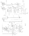
- Figure 1 helps to understand the entire electrohydraulic regulation system of the transmission, and in particular the part specific to piloting the lock-up clutch (1) of the converter (2), clutch which secures, when closed, the impeller (3) and the turbine (4) of the converter.
- the control device proposed by the invention comprises a pressure generation / regulation system of the type proposed by publication EP 0 187 051.
- a positive displacement pump (5) and a VRPL line pressure regulating valve (6) implemented according to the teaching of this document with different pressure limiting valves (7, 8 and 9) (VLP1.7, VLP3, and VLP6), so to generate regulated pressures at increasing constant levels.
- the valves (7, 8 and 9) thus create reference pressures P 1 , P 2 and P 3 , being indicative of 1.7 bar, 3 bar, and 6 bar.
- the pressure P 1 constitutes a first pressure reference level
- the pressure P 2 constitutes a second pressure reference level, used for supplying the modulating solenoid valves EVMPL (10) and EVMPC (11)
- the pressure P 3 constitutes a third pressure reference level, used for supplying the converter (2), the exchanger (12), and the lubrication circuit (13).
- EVMPL (10) supplied by the pressure P 2 , delivers on the channel (14), a modulated pressure P M1, varying between 0 and P 2 , acting on the differential surface of VRPL (6), so that, P M1 varying between 0 and P 2 , P L varying between P max / L and P 2 , the value of P max / L being fixed by adjusting the tare of the return spring (15) of VRPL (6). It follows that the pressure delivered by VLP6 is equal to P L if P 2 ⁇ P L ⁇ P 3 , and equal to P 3 , if P L ⁇ P 3 .
- the modulated pressure delivered by EVMPC (11) on channel (16) is zero: it follows that the RPC converter pressure control valve (17) is in the left stop position under the effect of the return spring (18), as well as the all or nothing drawer (19), constituting the CPC converter pressure switch valve, under the effect of its return spring (20). Under these conditions, the pressure delivered by VLP6 (9), passing through channel (21) at through the non-return valve (22), feeds the converter through the channel (23), crossing chambers 3 and 4 of CPC (19).
- the working fluid under pressure delivered by VLP6 (9) fills the lock-up clutch chamber (24), passes through the clutch (1), leaves the converter through the channel (25), and passes through the CPC chambers 6 and 7 (19) to the exchanger (12) via the canal (26) to reach, through the non-return valve (27), the circuit lubrication (13).
- the CPC all-or-nothing drawer (19) has tilted to the right, under the action of the modulated pressure P M2 , delivered by EVMPC (11) on its end 1.
- the chamber (24) of the the bridging clutch is set to zero by the channel (23) passing through the chambers 4 and 5 of the drawer (19).
- the EVMPC solenoid valve (11) delivers a modulated pressure P M2 , which, via the channel (16), acts on the face 8 of RPC (17), and puts the latter in a regulation situation indeed, the pressure delivered by VLP6 (9) arrives on chamber 5 of RPC (17) to be partially, and in a controlled manner, zeroed by regulation on the right edge of chamber 7 of RPC (17).
- the clutch (1) is therefore activated by a pressure P conv , adjusted as a function of the pressure P M2 , delivered by EVMPC (11), itself controlled as a function of the torque to be transmitted by the computer.
- transmission electronics (not shown). The path of the oil towards the exchanger (12) and the lubrication circuit (13) will also be found without difficulty.
- CPC (19) takes place by the rise in pressure P M2 delivered by EVMPC (11), acting on the end 1 of CPC (19).
- CPC (19) is in equilibrium between the force T 20 exerted on its end 1 by P M2 , and the force exerted by the spring (20), increased by the thrust exerted on the end 9 of CPC (19) by the fraction 1 / ⁇ of the pressure P 1 , ⁇ being the rate of attenuation of the hydraulic potentiometer constituted by the calibrated nozzles (30 and 31).
- CPC (19) design of CPC (19), and in particular of the power supply to its chambers 9 and 10, allows bistable operation of CPC (19), which favors, due to the very low exposure of the chamber 10 in situation "Bridged", an ultra-fast return to the "unhappy” situation: this last characteristic is especially beneficial to avoid stalling the engine - disastrous in automatic transmission or CVT -, during a wheel lock on sudden brake application .
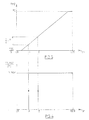
- bistable nature of the operation of CPC (19) makes it easy to be satisfied with a single modulating solenoid valve EVMPC (11), to ensure both the operation of CPC (19), and the operation in regulation of RPC (17). Indeed, if we refer to FIG. 4, we see that the bistable operation of CPC (19) can be represented by the hysteresis diagram CPC stroke (19) / control signal of EVMPC (11), that is to say X / Your.
- the device according to the invention therefore makes it possible to ensure a bistable operation of CPC (19), by favoring an ultra-rapid return to the "unmatched" situation, by being satisfied with a single modulating solenoid valve, EVMPC (11), which controls the operation of CPC (19), while retaining almost all of its operating range to be able to ensure fine regulation of P conv : indeed, the entire segment A + ⁇ -100% is available for regulation, it is to say in practice 15-100%.
Landscapes
- Engineering & Computer Science (AREA)
- General Engineering & Computer Science (AREA)
- Mechanical Engineering (AREA)
- Control Of Transmission Device (AREA)
- Control Of Fluid Gearings (AREA)
Claims (12)
- Verfahren zur Steuerung einer Überbrückungskupplung für einen hydrokinetischen Drehmomentwandler in einem Automatikgetriebe, mit einem einzigen Elektroventil (11), das mittels des gleichen modulierten Drucks PM2 den Übergang in den Zustand der Überbrückung des Wandlers oder in den Zustand ohne Überbrückung des Wandlers steuert sowie die Regelung des Steuerdrucks Pconv der Überbrückungskupplung im Zustand der Überbrückung, wobei die Steuerung des Übergangs in den Zustand der Überbrückung oder in den Zustand ohne Überbrückung mittels eines Schiebers (19) für die Offenstellung oder für die Schließstellung erfolgt, der eine bistabile Betriebsweise aufweist, die seine schnelle Rückkehr in den Zustand ohne Überbrückung unterstützt, dadurch gekennzeichnet, dass eine sehr geringe Verschiebung des Schiebers (19) ausgehend von seiner Stellung der Überbrückung als Folge des Zurücksetzens des modulierten Drucks PM2 auf Null seine schnelle Rückkehr in die Stellung ohne Überbückung auslöst durch Einwirkung einer hydraulischen Druckkraft in diese Richtung.
- Verfahren zur Steuerung nach Anspruch 1, dadurch gekennzeichnet, dass die hydraulische Druckkraft auf den Schieber (19) einwirkt, sowie die Abdeckung einer ihrer Kammern (10) beendet wird, die in der Stellung der Überbrückung die Verbindung eines Referenzdrucks P1 mit dem Sumpf herstellt.
- Verfahren zur Steuerung nach Anspruch 1 oder 2, dadurch gekennzeichnet, dass das Steuersignal Ton des Elektroventils (11) eine erste Schelle B aufweist, deren Überschreiten in zunehmender Richtung während einer ausreichend kurzen Zeit das Umschalten des Schiebers (19) in die Stellung der Überbrückung auslöst ohne Beeinflussung der Regelung des Steuerdrucks Pconv der Überbrückungskupplung, sowie eine zweite Schwelle aufweist, die kleiner ist als die erste Schwelle und oberhalb derer dieses Signal den Steuerdruck Pconv der Überbrückungskupplung regelt ohne eine Umschaltung des Schiebers in die Position ohne Überbrückung auszulösen.
- Verfahren zur Steuerung nach einem der vorhergehenden Ansprüchen 1, 2 oder 3, dadurch gekennzeichnet, dass der Versorgungsdruck Pconv des Wandlers eine Funktion des modulierten Drucks PM2 ist, der von dem Elektroventil (11) erzeugt wird.
- Verfahren zur Steuerung nach Anspruch 4, dadurch gekennzeichnet, dass der Versorgungsdruck Pconv des Wandlers eine lineare Funktion des modulierten Drucks PM2 ist, der durch die Gleichung bestimmt ist:
- Verfahren zur Steuerung nach einem der vorhergehenden Ansprüche, dadurch gekennzeichnet, dass der Druck PM2 moduliert wird ausgehend von einem Referenzdruck P2 > P1,
wobei P1 und P2 erhalten werden ausgehend vom selben Leitungsdruck PL mittels eines gemeinsamen Regelventils VRPL (6) für den Leitungsdruck und
Druckbegrenzungsventilen VLP3 (8) bzw. VLP1.7 (7). - Verfahren zur Steuerung nach Anspruch 6, dadurch gekennzeichnet, dass der Wandler im Zustand ohne Überbrückung mit einem Referenzdruck P3 > P2 versorgt wird, der mittels des Ventils (6) und des Druckbegrenzungsventils VLP 6 (9) erzeugt wird oder mit einem Leitungsdruck PL, je nachdem, ob PL > P3 oder P2 < PL < P3 ist.
- Verfahren zur Steuerung nach einem der vorhergehenden Ansprüche, dadurch gekennzeichnet, dass das Ventil (6) den Leitungsdruck PL regelt unter der Einwirkung eines modulierten Drucks PM1, der vom Elektroventil (10) für die Modulation des Leitungsdrucks erzeugt wird ausgehend von dem Referenzdruck P2.
- Verfahren zur Steuerung nach Anspruch 8, dadurch gekennzeichnet, dass der Leitungsdruck PL zwischen P2 und einem festen Maximalwert P1 max variierbar ist durch Einstellung der Rückholfeder (15) des Ventils )6).
- Vorrichtung zur Steuerung der Überbrückungskupplung eines hydrokinetischen Drehmomentwandlers für ein Automatikgetriebe, mit einem Schieber (19) für die Offenstellung oder die Schließstellung zum Umschalten von der Stellung mit Überbrückung in die Stellung ohne Überbrückung des Wandlers, mit einem Steuerschieber (17) für die Regelung des Steuerdrucks Pconv der Überbrückungskupplung in der Stellung mit Überbrückung und mit einem modulierenden Elektroventil (11) für den Druck, das die beiden Schieber (19) und (17) steuert mittels desselben modulierten Drucks PM2, dadurch gekennzeichnet, dass der Schieber (19) eine bistabile Betriebsweise aufweist, das seine Verschiebung in die Stellung ohne Überbrückung unterstützt und dass eine sehr geringe Verschiebung des Schiebers (19) ausgehend von seiner Stellung mit Überbrückung als Folge einer Rückkehr zu Null des modulierten Drucks PM2 seine schnelle Verschiebung in die Stellung ohne Überbrückung auslöst, ohne dass in dieser Richtung eine hydraulische Druckkraft wirksam ist.
- Vorrichtung zur Steuerung nach Anspruch 10, dadurch gekennzeichnet, dass sie ein Regelventil (6) für den Leitungsdruck aufweist, das stromaufwärts der drei Druckbegrenzungsventile (7, 6, 9) angeordnet ist, die drei Referenzdrücke P1, P2, P3 erzeugen, wobei P1 < P2 < P3 ist, die verwendet werden für:die Ausübung einer hydraulischen Druckkraft auf den Schieber (19) zur Beschleunigung seiner Verschiebung in Richtung der Stellung ohne Überbrückung,das Erzeugen des modulierten Drucks PM2 unddie Versorgung des Wandlers in der Stellung ohne Überbrückung, wenn der Leitungsdruck grösser als dieser ist.
- Vorrichtung zur Steuerung nach Anspruch 11, dadurch gekennzeichnet, dass der Referenzdruck P2 von einem Elektroventil (10) verwendet wird zur Modulation des Leitungsdrucks, das mit dem Regelventil (6) verbunden ist.
Applications Claiming Priority (2)
| Application Number | Priority Date | Filing Date | Title |
|---|---|---|---|
| FR9801670A FR2774737B1 (fr) | 1998-02-12 | 1998-02-12 | Procede et dispositif de pilotage d'un embrayage de pontage de convertisseur |
| FR9801670 | 1998-02-12 |
Publications (2)
| Publication Number | Publication Date |
|---|---|
| EP0936386A1 EP0936386A1 (de) | 1999-08-18 |
| EP0936386B1 true EP0936386B1 (de) | 2003-07-16 |
Family
ID=9522884
Family Applications (1)
| Application Number | Title | Priority Date | Filing Date |
|---|---|---|---|
| EP19990400320 Expired - Lifetime EP0936386B1 (de) | 1998-02-12 | 1999-02-11 | Verfahren und Vorrichtung zur Steuerung der Überbrückungskupplung eines Drehmomentenwandlers |
Country Status (3)
| Country | Link |
|---|---|
| EP (1) | EP0936386B1 (de) |
| DE (1) | DE69909537T2 (de) |
| FR (1) | FR2774737B1 (de) |
Family Cites Families (4)
| Publication number | Priority date | Publication date | Assignee | Title |
|---|---|---|---|---|
| US4468988A (en) * | 1980-08-04 | 1984-09-04 | Mitsubishi Jidosha Kogyo Kabushiki Kaisha | Slip control system for a clutch |
| FR2570521B1 (fr) | 1984-09-18 | 1987-12-11 | Renault | Dispositif de regulation a deux domaines de pression |
| JP2804799B2 (ja) * | 1989-09-08 | 1998-09-30 | ジャトコ株式会社 | ロックアップクラッチの油圧制御装置 |
| US4998604A (en) * | 1990-02-12 | 1991-03-12 | General Motors Corporation | Variable capacity control apparatus for an automotive torque converter clutch |
-
1998
- 1998-02-12 FR FR9801670A patent/FR2774737B1/fr not_active Expired - Lifetime
-
1999
- 1999-02-11 DE DE1999609537 patent/DE69909537T2/de not_active Expired - Lifetime
- 1999-02-11 EP EP19990400320 patent/EP0936386B1/de not_active Expired - Lifetime
Also Published As
| Publication number | Publication date |
|---|---|
| EP0936386A1 (de) | 1999-08-18 |
| FR2774737B1 (fr) | 2000-03-17 |
| DE69909537T2 (de) | 2004-06-03 |
| FR2774737A1 (fr) | 1999-08-13 |
| DE69909537D1 (de) | 2003-08-21 |
Similar Documents
| Publication | Publication Date | Title |
|---|---|---|
| FR2892787A1 (fr) | Dispositif de commande de rapport de vitesse pour transmission de vehicule variable continument | |
| FR2646464A1 (fr) | Procede et ensemble de commande d'un appareil de forage de roches | |
| FR2698138A1 (fr) | Système pour refroidir un embrayage de démarrage d'une boîte de vitesse variable en continu. | |
| EP0991858A1 (de) | In einer abgasleitung angeordnete bremsvorrichtung eines fahrzeuges mit brennkraftmaschine | |
| EP2861893B1 (de) | Verfahren zur steuerung eines hydrauliksystems und derartiges hydrauliksystem | |
| FR2672364A1 (fr) | Transmission graduellement reglable du type a poulies coniques. | |
| EP0571275B1 (de) | Steuervorrichtung für ein automatisches Stufengetriebe | |
| EP0936386B1 (de) | Verfahren und Vorrichtung zur Steuerung der Überbrückungskupplung eines Drehmomentenwandlers | |
| FR2672090A1 (fr) | Systeme d'entrainement hydraulique, notamment destine a une excavatrice. | |
| FR2515582A1 (fr) | Installation de commande pour une transmission de preference hydraulique, susceptible d'etre reglee en continu | |
| EP0021259B1 (de) | Steuervorrichtung für eine Überbrückungskupplung eines hydrodynamischen Drehmomentwandlers | |
| FR2552190A1 (fr) | Transmission automatique pourvue d'un dispositif antirampement | |
| FR2501142A1 (fr) | Dispositif d'entrainement auxiliaire d'un essieu de vehicule en remorque | |
| FR2687752A1 (fr) | Transmission a disques coniques, reglable en continu, notamment pour vehicules automobiles. | |
| FR2559435A1 (fr) | Dispositif de maintien a l'arret pour vehicule automobile muni d'une transmission automatique | |
| FR2574889A1 (fr) | Dispositif de commande d'une transmission automatique d'automobile | |
| EP0249529A1 (de) | Kraftübertragungseinrichtung für Brandbekämpfungsfahrzeug | |
| EP0088857B1 (de) | Hydraulischer Bremskreis für Kraftfahrzeuge | |
| EP0192899B1 (de) | Abwürgsicherung für ein hydraulisches System | |
| FR2651465A1 (fr) | Dispositif de transmission pour vehicule de lutte contre l'incendie. | |
| EP0176445B1 (de) | Steuervorrichtung für ein stufenlos regelbares Getriebe | |
| EP1387776A1 (de) | Schaltung für hydrostatisches fahrzeuggetriebe | |
| FR2647078A1 (fr) | Ensemble de direction assistee pour vehicule | |
| FR2720811A1 (fr) | Groupe motopropulseur hydraulique. | |
| FR2493455A2 (fr) | Dispositif hydrodynamique pour transmettre un couple mecanique, et notamment frein hydrodynamique |
Legal Events
| Date | Code | Title | Description |
|---|---|---|---|
| PUAI | Public reference made under article 153(3) epc to a published international application that has entered the european phase |
Free format text: ORIGINAL CODE: 0009012 |
|
| AK | Designated contracting states |
Kind code of ref document: A1 Designated state(s): DE ES GB IT |
|
| AX | Request for extension of the european patent |
Free format text: AL;LT;LV;MK;RO;SI |
|
| 17P | Request for examination filed |
Effective date: 20000204 |
|
| AKX | Designation fees paid |
Free format text: DE ES GB IT |
|
| 17Q | First examination report despatched |
Effective date: 20020204 |
|
| RAP1 | Party data changed (applicant data changed or rights of an application transferred) |
Owner name: RENAULT S.A.S. |
|
| GRAH | Despatch of communication of intention to grant a patent |
Free format text: ORIGINAL CODE: EPIDOS IGRA |
|
| GRAH | Despatch of communication of intention to grant a patent |
Free format text: ORIGINAL CODE: EPIDOS IGRA |
|
| GRAA | (expected) grant |
Free format text: ORIGINAL CODE: 0009210 |
|
| AK | Designated contracting states |
Designated state(s): DE ES GB IT |
|
| PG25 | Lapsed in a contracting state [announced via postgrant information from national office to epo] |
Ref country code: IT Free format text: LAPSE BECAUSE OF FAILURE TO SUBMIT A TRANSLATION OF THE DESCRIPTION OR TO PAY THE FEE WITHIN THE PRESCRIBED TIME-LIMIT;WARNING: LAPSES OF ITALIAN PATENTS WITH EFFECTIVE DATE BEFORE 2007 MAY HAVE OCCURRED AT ANY TIME BEFORE 2007. THE CORRECT EFFECTIVE DATE MAY BE DIFFERENT FROM THE ONE RECORDED. Effective date: 20030716 Ref country code: GB Free format text: LAPSE BECAUSE OF FAILURE TO SUBMIT A TRANSLATION OF THE DESCRIPTION OR TO PAY THE FEE WITHIN THE PRESCRIBED TIME-LIMIT Effective date: 20030716 |
|
| REG | Reference to a national code |
Ref country code: GB Ref legal event code: FG4D Free format text: NOT ENGLISH |
|
| REF | Corresponds to: |
Ref document number: 69909537 Country of ref document: DE Date of ref document: 20030821 Kind code of ref document: P |
|
| PG25 | Lapsed in a contracting state [announced via postgrant information from national office to epo] |
Ref country code: ES Free format text: LAPSE BECAUSE OF FAILURE TO SUBMIT A TRANSLATION OF THE DESCRIPTION OR TO PAY THE FEE WITHIN THE PRESCRIBED TIME-LIMIT Effective date: 20031027 |
|
| GBV | Gb: ep patent (uk) treated as always having been void in accordance with gb section 77(7)/1977 [no translation filed] |
Effective date: 20030716 |
|
| PLBE | No opposition filed within time limit |
Free format text: ORIGINAL CODE: 0009261 |
|
| STAA | Information on the status of an ep patent application or granted ep patent |
Free format text: STATUS: NO OPPOSITION FILED WITHIN TIME LIMIT |
|
| 26N | No opposition filed |
Effective date: 20040419 |
|
| PGFP | Annual fee paid to national office [announced via postgrant information from national office to epo] |
Ref country code: DE Payment date: 20170217 Year of fee payment: 19 |
|
| REG | Reference to a national code |
Ref country code: DE Ref legal event code: R119 Ref document number: 69909537 Country of ref document: DE |
|
| PG25 | Lapsed in a contracting state [announced via postgrant information from national office to epo] |
Ref country code: DE Free format text: LAPSE BECAUSE OF NON-PAYMENT OF DUE FEES Effective date: 20180901 |