EP0936386B1 - Method and device for the control of a torque converter lock-up clutch - Google Patents
Method and device for the control of a torque converter lock-up clutch Download PDFInfo
- Publication number
- EP0936386B1 EP0936386B1 EP19990400320 EP99400320A EP0936386B1 EP 0936386 B1 EP0936386 B1 EP 0936386B1 EP 19990400320 EP19990400320 EP 19990400320 EP 99400320 A EP99400320 A EP 99400320A EP 0936386 B1 EP0936386 B1 EP 0936386B1
- Authority
- EP
- European Patent Office
- Prior art keywords
- pressure
- bridging
- valve
- piloting
- converter
- Prior art date
- Legal status (The legal status is an assumption and is not a legal conclusion. Google has not performed a legal analysis and makes no representation as to the accuracy of the status listed.)
- Expired - Lifetime
Links
Images

Classifications
-
- F—MECHANICAL ENGINEERING; LIGHTING; HEATING; WEAPONS; BLASTING
- F16—ENGINEERING ELEMENTS AND UNITS; GENERAL MEASURES FOR PRODUCING AND MAINTAINING EFFECTIVE FUNCTIONING OF MACHINES OR INSTALLATIONS; THERMAL INSULATION IN GENERAL
- F16H—GEARING
- F16H61/00—Control functions within control units of change-speed- or reversing-gearings for conveying rotary motion ; Control of exclusively fluid gearing, friction gearing, gearings with endless flexible members or other particular types of gearing
- F16H61/02—Control functions within control units of change-speed- or reversing-gearings for conveying rotary motion ; Control of exclusively fluid gearing, friction gearing, gearings with endless flexible members or other particular types of gearing characterised by the signals used
- F16H61/0202—Control functions within control units of change-speed- or reversing-gearings for conveying rotary motion ; Control of exclusively fluid gearing, friction gearing, gearings with endless flexible members or other particular types of gearing characterised by the signals used the signals being electric
- F16H61/0251—Elements specially adapted for electric control units, e.g. valves for converting electrical signals to fluid signals
-
- F—MECHANICAL ENGINEERING; LIGHTING; HEATING; WEAPONS; BLASTING
- F16—ENGINEERING ELEMENTS AND UNITS; GENERAL MEASURES FOR PRODUCING AND MAINTAINING EFFECTIVE FUNCTIONING OF MACHINES OR INSTALLATIONS; THERMAL INSULATION IN GENERAL
- F16H—GEARING
- F16H61/00—Control functions within control units of change-speed- or reversing-gearings for conveying rotary motion ; Control of exclusively fluid gearing, friction gearing, gearings with endless flexible members or other particular types of gearing
- F16H61/14—Control of torque converter lock-up clutches
- F16H61/143—Control of torque converter lock-up clutches using electric control means
Definitions
- the present invention relates to the hydraulic control of automatic transmissions.
- the vibrations can be combated by the interposition of a shock absorber hub, more or less sophisticated and bulky, or, in a way that tends to develop, by allowing the override clutch to slide carefully controlled under certain torque and speed conditions engine.
- this slip is controlled by means of a complex electro-hydraulic control system supervised by the electronic computer of the BVA or CVT, taking into account, as input variables, the torque C m and the engine speed ⁇ m , the turbine speed the temperature, temperature of the working fluid of the BVA, etc. From these measured data, the computer develops a slip instruction ( ⁇ m - ⁇ t ), and it is by regulating the clamping pressure of the converter lock-up clutch by means of a controlled electro-hydraulic system that we endeavor to comply with this slip instruction: in slip mode, the lock-up clutch works as a torque limiter, and in so doing, smooths out irregularities in the engine torque effectively, thereby achieving the desired acoustic performance.
- the most commonly used electrohydraulic systems to adjust the clamping pressure of the lockup clutch generally have a hydraulic drawer controlled by an all-or-nothing solenoid valve that distinguishes between "bridged” and “Unmounted”, and a regulation drawer controlled by a solenoid valve modulating, which develops, from a reference pressure, the control pressure sought.
- the modulating solenoid valve is itself activated by an appropriate signal, delivered by the computer of the BVA.
- the publication US 4998 604 describes another method for controlling a torque converter lock-up clutch corresponding to the preamble of claim 1 and involving a all or nothing drawer whose rest position is the position of constrainontage.
- the invention aims to achieve a system that is both less expensive and less bulky, but offering equivalent performance, while optimizing return to the disassembly position.
- the all or nothing drawer has a bistable functioning, favoring its rapid return to the disassembly position.
- the invention thus makes it possible to facilitate the tilting of this drawer between its two positions.
- the invention also provides specific management of the signal solenoid valve control responsible for bypass control and regulation.
- this signal has a first threshold whose crossing in an increasing direction for a time sufficiently short triggers the tilting of the control drawer bridging in the bridging position without affecting the regulation of the clutch pilot pressure, and a second lower threshold on the first, above which this signal controls the regulation, without trigger the tilting of said drawer in the disassembly position.
- the invention further relates to a device for controlling a hydrokinetic converter bypass clutch automatic transmission torque, including a full drawer or nothing bypass control or removal of the converter, a pilot pressure regulation drawer lock-up clutch in the lock-up situation, and modulating solenoid valve.
- This device is characterized in that the solenoid valve controls the two drawers, using the same modulated pressure.
- the bridging control drawer has bistable operation, favoring its displacement in the disassembly position.
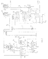
- Figure 1 helps to understand the entire electrohydraulic regulation system of the transmission, and in particular the part specific to piloting the lock-up clutch (1) of the converter (2), clutch which secures, when closed, the impeller (3) and the turbine (4) of the converter.
- the control device proposed by the invention comprises a pressure generation / regulation system of the type proposed by publication EP 0 187 051.
- a positive displacement pump (5) and a VRPL line pressure regulating valve (6) implemented according to the teaching of this document with different pressure limiting valves (7, 8 and 9) (VLP1.7, VLP3, and VLP6), so to generate regulated pressures at increasing constant levels.
- the valves (7, 8 and 9) thus create reference pressures P 1 , P 2 and P 3 , being indicative of 1.7 bar, 3 bar, and 6 bar.
- the pressure P 1 constitutes a first pressure reference level
- the pressure P 2 constitutes a second pressure reference level, used for supplying the modulating solenoid valves EVMPL (10) and EVMPC (11)
- the pressure P 3 constitutes a third pressure reference level, used for supplying the converter (2), the exchanger (12), and the lubrication circuit (13).
- EVMPL (10) supplied by the pressure P 2 , delivers on the channel (14), a modulated pressure P M1, varying between 0 and P 2 , acting on the differential surface of VRPL (6), so that, P M1 varying between 0 and P 2 , P L varying between P max / L and P 2 , the value of P max / L being fixed by adjusting the tare of the return spring (15) of VRPL (6). It follows that the pressure delivered by VLP6 is equal to P L if P 2 ⁇ P L ⁇ P 3 , and equal to P 3 , if P L ⁇ P 3 .
- the modulated pressure delivered by EVMPC (11) on channel (16) is zero: it follows that the RPC converter pressure control valve (17) is in the left stop position under the effect of the return spring (18), as well as the all or nothing drawer (19), constituting the CPC converter pressure switch valve, under the effect of its return spring (20). Under these conditions, the pressure delivered by VLP6 (9), passing through channel (21) at through the non-return valve (22), feeds the converter through the channel (23), crossing chambers 3 and 4 of CPC (19).
- the working fluid under pressure delivered by VLP6 (9) fills the lock-up clutch chamber (24), passes through the clutch (1), leaves the converter through the channel (25), and passes through the CPC chambers 6 and 7 (19) to the exchanger (12) via the canal (26) to reach, through the non-return valve (27), the circuit lubrication (13).
- the CPC all-or-nothing drawer (19) has tilted to the right, under the action of the modulated pressure P M2 , delivered by EVMPC (11) on its end 1.
- the chamber (24) of the the bridging clutch is set to zero by the channel (23) passing through the chambers 4 and 5 of the drawer (19).
- the EVMPC solenoid valve (11) delivers a modulated pressure P M2 , which, via the channel (16), acts on the face 8 of RPC (17), and puts the latter in a regulation situation indeed, the pressure delivered by VLP6 (9) arrives on chamber 5 of RPC (17) to be partially, and in a controlled manner, zeroed by regulation on the right edge of chamber 7 of RPC (17).
- the clutch (1) is therefore activated by a pressure P conv , adjusted as a function of the pressure P M2 , delivered by EVMPC (11), itself controlled as a function of the torque to be transmitted by the computer.
- transmission electronics (not shown). The path of the oil towards the exchanger (12) and the lubrication circuit (13) will also be found without difficulty.
- CPC (19) takes place by the rise in pressure P M2 delivered by EVMPC (11), acting on the end 1 of CPC (19).
- CPC (19) is in equilibrium between the force T 20 exerted on its end 1 by P M2 , and the force exerted by the spring (20), increased by the thrust exerted on the end 9 of CPC (19) by the fraction 1 / ⁇ of the pressure P 1 , ⁇ being the rate of attenuation of the hydraulic potentiometer constituted by the calibrated nozzles (30 and 31).
- CPC (19) design of CPC (19), and in particular of the power supply to its chambers 9 and 10, allows bistable operation of CPC (19), which favors, due to the very low exposure of the chamber 10 in situation "Bridged", an ultra-fast return to the "unhappy” situation: this last characteristic is especially beneficial to avoid stalling the engine - disastrous in automatic transmission or CVT -, during a wheel lock on sudden brake application .
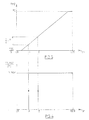
- bistable nature of the operation of CPC (19) makes it easy to be satisfied with a single modulating solenoid valve EVMPC (11), to ensure both the operation of CPC (19), and the operation in regulation of RPC (17). Indeed, if we refer to FIG. 4, we see that the bistable operation of CPC (19) can be represented by the hysteresis diagram CPC stroke (19) / control signal of EVMPC (11), that is to say X / Your.
- the device according to the invention therefore makes it possible to ensure a bistable operation of CPC (19), by favoring an ultra-rapid return to the "unmatched" situation, by being satisfied with a single modulating solenoid valve, EVMPC (11), which controls the operation of CPC (19), while retaining almost all of its operating range to be able to ensure fine regulation of P conv : indeed, the entire segment A + ⁇ -100% is available for regulation, it is to say in practice 15-100%.
Landscapes
- Engineering & Computer Science (AREA)
- General Engineering & Computer Science (AREA)
- Mechanical Engineering (AREA)
- Control Of Transmission Device (AREA)
- Control Of Fluid Gearings (AREA)
Description
La présente invention se rapporte au pilotage hydraulique des transmissions automatiques.The present invention relates to the hydraulic control of automatic transmissions.
Plus précisément, elle concerne un procédé et un dispositif de pilotage d'un embrayage de pontage de transmission automatique.More specifically, it relates to a method and a device for driving a transmission lockup clutch automatic.
Pour optimiser la consommation des véhicules équipés de boítes de vitesses automatiques étagées (BVA) ou à variation continue (CVT), équipées d'un convertisseur de couple, il est connu de munir le convertisseur de couple d'un embrayage de pontage entre l'impulseur et la turbine de ce dernier. Cet embrayage permet, lorsqu'il est fermé hors des phases de conversion, d'annuler le glissement du convertisseur, et d'améliorer d'autant le rendement de la transmission. Néanmoins, le fait de ponter le convertisseur supprime l'effet bénéfique de filtrage des acyclismes moteur, filtrage que procure tout naturellement le convertisseur. Il en résulte que le pontage du convertisseur induit, si l'on ne prend pas les contremesures indispensables, un risque important d'apparition de vibrations indésirables dans la chaíne cinématique. To optimize the consumption of vehicles equipped with stepped or variable automatic gearboxes continuous (CVT), equipped with a torque converter, it is known to provide the torque converter with a clutch of bridging between the impeller and the latter's turbine. This clutch allows, when closed out of phases conversion, cancel the converter slip, and improve the efficiency of the transmission accordingly. However, bridging the converter removes the effect beneficial filtering of motor acyclisms, filtering that naturally provides the converter. As a result, the induced converter bridging, if the countermeasures are not taken essential, a significant risk of the appearance of undesirable vibrations in the kinematic chain.
Les vibrations peuvent être combattues par l'interposition d'un moyeu amortisseur, plus ou moins sophistiqué et encombrant, ou, d'une manière qui tend à se développer, en autorisant l'embrayage de pontage à glisser de façon soigneusement contrôlée dans certaines conditions de couple et de vitesse moteur.The vibrations can be combated by the interposition of a shock absorber hub, more or less sophisticated and bulky, or, in a way that tends to develop, by allowing the override clutch to slide carefully controlled under certain torque and speed conditions engine.
Dans la totalité des applications, le pilotage de ce glissement s'opère au moyen d'un système de contrôle électrohydraulique complexe supervisé par le calculateur électronique de la BVA ou du CVT, prenant notamment en compte, comme grandeurs d'entrée, le couple Cm et la vitesse moteur ωm, la vitesse turbine la température température du fluide de travail de la BVA, etc.... A partir de ces données mesurées, le calculateur élabore une consigne de glissement (ωm - ωt), et c'est en régulant la pression de serrage de l'embrayage de pontage du convertisseur au moyen d'un système électrohydraulique piloté, que l'on s'efforce de respecter cette consigne de glissement : en régime de glissement, l'embrayage de pontage fonctionne comme un limiteur de couple, et ce faisant, lisse efficacement les irrégularités du couple moteur, permettant ainsi d'atteindre les prestations acoustiques souhaitées.In all applications, this slip is controlled by means of a complex electro-hydraulic control system supervised by the electronic computer of the BVA or CVT, taking into account, as input variables, the torque C m and the engine speed ω m , the turbine speed the temperature, temperature of the working fluid of the BVA, etc. From these measured data, the computer develops a slip instruction (ω m - ω t ), and it is by regulating the clamping pressure of the converter lock-up clutch by means of a controlled electro-hydraulic system that we endeavor to comply with this slip instruction: in slip mode, the lock-up clutch works as a torque limiter, and in so doing, smooths out irregularities in the engine torque effectively, thereby achieving the desired acoustic performance.
Les systèmes électrohydrauliques les plus couramment utilisés pour régler la pression de serrage de l'embrayage de pontage, comportent généralement un tiroir hydraulique commandé par une électrovanne tout ou rien qui distingue les états «ponté» et «déponté», et un tiroir de régulation commandé par une électrovanne modulante, qui élabore, partir d'une pression de référence, la pression de commande recherchée. L'électrovanne modulante est elle-même activée par un signal approprié, délivré par le calculateur de la BVA. Un tel système est à la fois cher et encombrant, puisqu'il nécessite deux électrovannes.The most commonly used electrohydraulic systems to adjust the clamping pressure of the lockup clutch, generally have a hydraulic drawer controlled by an all-or-nothing solenoid valve that distinguishes between "bridged" and "Unmounted", and a regulation drawer controlled by a solenoid valve modulating, which develops, from a reference pressure, the control pressure sought. The modulating solenoid valve is itself activated by an appropriate signal, delivered by the computer of the BVA. Such a system is both expensive and cumbersome, since it requires two solenoid valves.
Par la publication GB 2081413, on connaít un procédé de pilotage d'un embrayage de convertisseur de couple de transmission automatique, selon lequel une électrovanne commande le pontage ou le dépontage du convertisseur, ainsi que la régulation de la pression de pilotage correspondante.By the publication GB 2081413, we know a method of piloting a automatic transmission torque converter clutch, according to which a solenoid valve controls bridging or dismounting of the converter, as well as the regulation of the pilot pressure corresponding.
La publication US 4998 604 décrit un autre procédé de pilotage d'un
embrayage de pontage de convertisseur de couple
correspondant au préambule de la revendication 1 et faisant intervenir un
tiroir tout ou rien dont la position de repos est la position de
dépontage.The publication US 4998 604 describes another method for controlling a
torque converter lock-up clutch
corresponding to the preamble of
L'invention vise à réaliser un système à la fois moins coûteux et moins encombrant, mais offrant des performances équivalentes, tout en optimisant le retour en position de dépontage.The invention aims to achieve a system that is both less expensive and less bulky, but offering equivalent performance, while optimizing return to the disassembly position.
Elle propose dans ce but une disposition constructive et un pilotage spécifiques du tiroir tout ou rien. En particulier, le tiroir tout ou rien a un fonctionnement bistable, privilégiant son retour rapide en position de dépontage.To this end, it offers a constructive arrangement and management of the all or nothing drawer. In particular, the all or nothing drawer has a bistable functioning, favoring its rapid return to the disassembly position.
L'invention permet ainsi de faciliter le basculement de ce tiroir entre ses deux positions.The invention thus makes it possible to facilitate the tilting of this drawer between its two positions.
En particulier, il est proposé qu'un déplacement très faible du tiroir tout ou rien à partir de sa position de pontage en réponse au retour à zéro de la pression modulée, déclenche le déplacement rapide de celui-ci en position de dépontage.In particular, it is proposed that a very small displacement of the drawer all or nothing from its bridging position in response to returning to zero of the modulated pressure, triggers its rapid displacement in the disassembly position.
L'invention propose également une gestion spécifique du signal de commande de l'électrovanne responsable de la commande du pontage et de la régulation.The invention also provides specific management of the signal solenoid valve control responsible for bypass control and regulation.
Conformément à l'invention, ce signal présente un premier seuil dont le franchissement dans un sens croissant pendant un temps suffisamment bref déclenche le basculement du tiroir de commande du pontage en position de pontage sans avoir d'incidence sur la régulation de la pression de pilotage de l'embrayage, et un second seuil inférieur au premier, au dessus duquel ce signal commande la régulation, sans déclencher le basculement dudit tiroir en position de dépontage. According to the invention, this signal has a first threshold whose crossing in an increasing direction for a time sufficiently short triggers the tilting of the control drawer bridging in the bridging position without affecting the regulation of the clutch pilot pressure, and a second lower threshold on the first, above which this signal controls the regulation, without trigger the tilting of said drawer in the disassembly position.
L'invention concerne par ailleurs un dispositif de pilotage d'un embrayage de pontage de convertisseur hydrocinétique de couple de transmission automatique, comportant un tiroir tout ou rien de commande de pontage ou de dépontage du convertisseur, un tiroir de régulation de la pression de pilotage de l'embrayage de pontage en situation de pontage, et une électrovanne modulante.The invention further relates to a device for controlling a hydrokinetic converter bypass clutch automatic transmission torque, including a full drawer or nothing bypass control or removal of the converter, a pilot pressure regulation drawer lock-up clutch in the lock-up situation, and modulating solenoid valve.
Ce dispositif est caractérisé en ce que l'électrovanne commande les deux tiroirs, à l'aide de la même pression modulée.This device is characterized in that the solenoid valve controls the two drawers, using the same modulated pressure.
Selon un mode de réalisation préférentiel de ce dispositif, le tiroir de commande du pontage a un fonctionnement bistable, favorisant son déplacement en position de dépontage.According to a preferred embodiment of this device, the bridging control drawer has bistable operation, favoring its displacement in the disassembly position.
D'autres caractéristiques et avantages de l'invention apparaítront clairement à la lecture de la description suivante d'un mode de réalisation particulier de celle-ci, en se référant aux dessins annexés, sur lesquels :
- la figure 1 représente l'ensemble du système de régulation de la transmission, et notamment le système de pilotage du convertisseur pontable, en position «déponté»,
- la figure 2 représente le système de pilotage du convertisseur pontable, en position «ponté»,
- la figure 3 représente la caractéristique pression/signal de pilotage Ton, de l'électrovanne modulante, et
- la figure 4 représente le diagramme «position/signal de pilotage», du tiroir hydraulique tout ou rien.
- FIG. 1 represents the whole of the transmission regulation system, and in particular the control system of the bridgeable converter, in the “unhooked” position,
- FIG. 2 represents the control system of the bridgeable converter, in the “bridged” position,
- FIG. 3 represents the pressure / control signal characteristic Ton, of the modulating solenoid valve, and
- FIG. 4 represents the "position / piloting signal" diagram of the all-or-nothing hydraulic slide.
Comme indiqué ci-dessus, la figure 1 permet de comprendre l'ensemble du système de régulation électrohydraulique de la transmission, et notamment la partie spécifique au pilotage de l'embrayage de pontage (1) du convertisseur (2), embrayage qui solidarise, lorsqu'il est fermé, l'impulseur (3) et la turbine (4) du convertisseur.As indicated above, Figure 1 helps to understand the entire electrohydraulic regulation system of the transmission, and in particular the part specific to piloting the lock-up clutch (1) of the converter (2), clutch which secures, when closed, the impeller (3) and the turbine (4) of the converter.
Le dispositif de pilotage proposé par l'invention comporte un
système de génération /régulation de pression du type proposé
par la publication EP 0 187 051. On reconnaít en particulier, sur
la partie droite de la figure 1, une pompe volumétrique (5) et
une vanne de régulation de pression de ligne VRPL (6), mises
en oeuvre selon l'enseignement de ce document avec
différentes vannes de limitation de pression (7, 8 et 9) (VLP1.7,
VLP3, et VLP6), de façon à générer des pressions régulées à
niveaux constants croissants. A partir de la pression de ligne PL,
les vannes (7, 8 et 9) créent ainsi des pressions de référence P1,
P2 et P3, valant à titre indicatif 1,7 bar, 3 bar, et 6 bar. The control device proposed by the invention comprises a pressure generation / regulation system of the type proposed by
La pression P1 constitue un premier niveau de référence de pression, la pression P2 constitue un second niveau de référence de pression, utilisée pour l'alimentation des électrovannes modulantes EVMPL (10) et EVMPC (11), et la pression P3 constitue un troisième niveau de référence de pression, utilisée pour l'alimentation du convertisseur (2), de l'échangeur (12), et du circuit de graissage (13). EVMPL (10), alimentée par la pression P2, délivre sur le canal (14), une pression modulée PM1, variant entre 0 et P2, agissant sur la surface différentielle de VRPL (6), de telle manière que, PM1 variant entre 0 et P2, PL varie entre P max / L et P2, la valeur de P max / L étant fixée en ajustant la tare du ressort de rappel (15) de VRPL (6). Il en résulte que la pression délivrée par VLP6 est égale à PL si P2 ≤ PL ≤ P3, et égale à P3, si PL ≥ P3.The pressure P 1 constitutes a first pressure reference level, the pressure P 2 constitutes a second pressure reference level, used for supplying the modulating solenoid valves EVMPL (10) and EVMPC (11), and the pressure P 3 constitutes a third pressure reference level, used for supplying the converter (2), the exchanger (12), and the lubrication circuit (13). EVMPL (10), supplied by the pressure P 2 , delivers on the channel (14), a modulated pressure P M1, varying between 0 and P 2 , acting on the differential surface of VRPL (6), so that, P M1 varying between 0 and P 2 , P L varying between P max / L and P 2 , the value of P max / L being fixed by adjusting the tare of the return spring (15) of VRPL (6). It follows that the pressure delivered by VLP6 is equal to P L if P 2 ≤ P L ≤ P 3 , and equal to P 3 , if P L ≥ P 3 .
En situation «déponté», la pression modulée délivrée par
EVMPC (11) sur le canal (16) est nulle : il en résulte que la
vanne de régulation de la pression convertisseur RPC (17) est
en position de butée à gauche sous l'effet du ressort de rappel
(18), de même que le tiroir tout ou rien (19), constituant la
vanne de commutation de la pression convertisseur CPC, sous
l'effet de son ressort de rappel (20). Dans ces conditions, la
pression délivrée par VLP6 (9), transitant par le canal (21) à
travers le clapet anti-retour (22), alimente le convertisseur par le
canal (23), en traversant les chambres 3 et 4 de CPC (19). Le
fluide de travail sous pression délivré par VLP6 (9) remplit la
chambre (24) de l'embrayage de pontage, traverse l'embrayage
(1), ressort du convertisseur par le canal (25), et transite par les
chambres 6 et 7 de CPC (19) vers l'échangeur (12) par le canal
(26) pour atteindre, à travers le clapet anti-retour (27), le circuit
de graissage (13).In a "upset" situation, the modulated pressure delivered by
EVMPC (11) on channel (16) is zero: it follows that the
RPC converter pressure control valve (17) is
in the left stop position under the effect of the return spring
(18), as well as the all or nothing drawer (19), constituting the
CPC converter pressure switch valve, under
the effect of its return spring (20). Under these conditions, the
pressure delivered by VLP6 (9), passing through channel (21) at
through the non-return valve (22), feeds the converter through the
channel (23),
En situation «ponté», le tiroir tout ou rien CPC (19) a basculé
vers la droite, sous l'action de la pression modulée PM2, délivrée
par EVMPC (11) sur son extrémité 1. La chambre (24) de
l'embrayage de pontage est mise au zéro par le canal (23) en
traversant les chambres 4 et 5 du tiroir (19). L'électrovanne
EVMPC (11) délivre une pression modulée PM2, qui, par
l'intermédiaire du canal (16), agit sur la face 8 de RPC (17), et
met cette dernière en situation de régulation en effet, la
pression délivrée par VLP6 (9) arrive sur la chambre 5 de RPC
(17) pour être partiellement, et de manière contrôlée, mise au
zéro par régulation sur l'arête droite de la chambre 7 de RPC
(17). L'équation de régulation s'écrit : S.PM2 = T18 + S/α.Pconv,
soit
Le basculement de CPC (19) s'opère par la montée de la
pression PM2 délivrée par EVMPC (11), agissant sur l'extrémité
1 de CPC (19). En situation «déponté», CPC (19) est en équilibre
entre la force T20 exercée sur son extrémité 1 par PM2, et la force
exercée par le ressort (20), augmentée de la poussée exercée sur
l'extrémité 9 de CPC (19) par la fraction 1/β de la pression P1, β
étant le taux d'atténuation du potentiomètre hydraulique
constitué par les gicleurs calibrés (30 et 31).The switchover of CPC (19) takes place by the rise in pressure P M2 delivered by EVMPC (11), acting on the
Lorsque PM2 > (T20/S) + (1/β.P1) (a), CPC 19 se déplace vers la
droite, jusqu'à ce que la chambre 10 soit mise en
communication avec la chambre 9, elle-même à la bâche : la
pression tombe donc à zéro dans la chambre 10, le mouvement
de CPC (19) vers la droite s'accélère alors, jusqu'à ce que CPC
(19) se trouve en position en butée à droite , en situation
«ponté» : l'inéquation d'équilibre de la vanne CPC (19) devient
alors : PM2 > T20/S (b). Si l'on souhaite opérer un passage en
situation «déponté», il suffit de ramener PM2 à zéro. En
comparant les figures 1 et 2, on s'aperçoit que le découvrement
de la chambre 10 de CPC (19) en situation «ponté» est très faible
(de l'ordre de quelques dixièmes de millimètre), si bien que,
lors de l'opération de pontage à partir de la situation
«déponté», une translation très faible de CPC (19) vers la
gauche suffit à fermer la communication entre les chambres 9 et
10 : il en résulte alors la remise en pression par 1/β.P1 de la
chambre 10, ce qui a pour effet une accélération du mouvement
de CPC (19), vers sa position en butée, de situation «déponté».
On voit donc que la conception de CPC (19), et notamment de
l'alimentation de ses chambres 9 et 10, permet un
fonctionnement bistable de CPC (19), qui privilégie, en raison
du très faible découvrement de la chambre 10 en situation
«ponté», un retour ultra-rapide vers la situation «déponté» :
cette dernière particularité est tout spécialement bénéfique pour
éviter le calage du moteur -calamiteux en transmission
automatique ou CVT -, lors d'un blocage de roue sur coup de
frein brutal.When P M2 > (T 20 / S) + (1 / β.P 1 ) (a),
Le caractère bistable du fonctionnement de CPC (19) permet aisément de se contenter d'une seule électrovanne modulante EVMPC (11), pour assurer à la fois la manoeuvre de CPC (19), et le fonctionnement en régulation de RPC (17). En effet, si l'on se réfère à la figure 4, on voit que le fonctionnement bistable de CPC (19) est représentable par le diagramme en hystérésis course CPC (19)/signal de commande de EVMPC (11), soit X/Ton. Si ce diagramme est mis en regard avec la courbe caractéristique de EVMPC (11), PM2/Ton, on voit qu'à partir d'une situation «déponté», caractérisée par Ton = 0 au niveau du signal de commande, on désire passer en situation «ponté», il suffit d'envoyer à EVMPC (11) un signal B < Ton < 100% pendant un temps suffisant mais très bref (suffisamment bref pour que la valeur de Ton choisie n'ait pas de conséquences perceptibles sur la régulation de Pconv), pour faire basculer CPC (19). A l'issue de ce temps, l'intervalle A - 100% est disponible pour Ton pour la régulation de Pconv par RPC (17). Pour fixer des ordres de grandeur non limitatifs tirés de l'expérience, si P2 = 3 bar, on pourra prendre (T20/S) + (1/β.P1) ∼ 1 bar et (T20/S) ∼ 0.2 bar, soit β ∼ 2. Avec ces valeurs, on voit que T20 est faible : en effet, le rôle du ressort (20) est essentiellement d'assurer en toutes circonstances un prépositionnement sûr de CPC (19), en situation «déponté», pour Ton = 0. Avec B ∼ 2, les gicleurs sont sensiblement égaux en diamètre.The bistable nature of the operation of CPC (19) makes it easy to be satisfied with a single modulating solenoid valve EVMPC (11), to ensure both the operation of CPC (19), and the operation in regulation of RPC (17). Indeed, if we refer to FIG. 4, we see that the bistable operation of CPC (19) can be represented by the hysteresis diagram CPC stroke (19) / control signal of EVMPC (11), that is to say X / Your. If this diagram is compared with the characteristic curve of EVMPC (11), P M2 / Ton, we see that from a "unhappy" situation, characterized by Ton = 0 at the level of the control signal, we want to go into a “bridged” situation, it is enough to send to EVMPC (11) a signal B <Tone <100% for a sufficient but very short time (sufficiently short so that the value of Tone chosen has no perceptible consequences on the regulation of P conv ), to toggle CPC (19). At the end of this time, the interval A - 100% is available for Ton for the regulation of P conv by RPC (17). To fix nonlimiting orders of magnitude drawn from experience, if P 2 = 3 bar, we can take (T 20 / S) + (1 / β.P 1 ) ∼ 1 bar and (T 20 / S) ∼ 0.2 bar, ie β ∼ 2. With these values, we see that T 20 is weak: indeed, the role of the spring (20) is essentially to ensure in all circumstances a safe prepositioning of CPC (19), in situation """ for Ton = 0. With B ∼ 2, the nozzles are substantially equal in diameter.
Le dispositif selon l'invention permet donc d'assurer un fonctionnement bistable de CPC (19), en privilégiant un retour ultra-rapide à la situation «déponté», en se contentant d'une unique électrovanne modulante, EVMPC (11), qui commande la manoeuvre de CPC (19), tout en conservant quasiment la totalité de son domaine de fonctionnement pour pouvoir assurer une régulation fine de Pconv : en effet, tout le segment A+ε-100% est disponible pour la régulation, c'est à dire en pratique 15-100%. En fait, les extrémités de courbe caractéristique des électrovannes modulantes sont rarement exploitables en régulation, par dispersions exagérées, manque de linéarité, etc..., si bien que la perte réelle de domaine de régulation est, en pratique, inférieure à 15%, tout en permettant malgré tout de ne pas avoir à mettre en oeuvre une électrovanne tout ou rien spécialisée dans la commande de CPC (19).The device according to the invention therefore makes it possible to ensure a bistable operation of CPC (19), by favoring an ultra-rapid return to the "unmatched" situation, by being satisfied with a single modulating solenoid valve, EVMPC (11), which controls the operation of CPC (19), while retaining almost all of its operating range to be able to ensure fine regulation of P conv : indeed, the entire segment A + ε-100% is available for regulation, it is to say in practice 15-100%. In fact, the characteristic curve ends of the modulating solenoid valves are rarely usable in regulation, by exaggerated dispersions, lack of linearity, etc., so that the real loss of regulation domain is, in practice, less than 15%, while still allowing not to have to use an all or nothing solenoid valve specializing in the control of CPC (19).
Claims (12)
- A method for piloting a bridging clutch of a hydrokinetic torque converter of an automatic transmission, comprising a single electrovalve (11) which controls, by means of the same modulated pressure PM2, the bridging or non-bridging of the converter, and the regulation of the piloting pressure of the bridging clutch Pconv in a bridging situation, the control of the bridging and non-bridging being ensured by means of an all-or-nothing valve (19) having a bistable operation giving priority to its rapid return to a non-bridging position, characterised in that a very small displacement of the valve (19) from its bridging position in response to the return to zero of the modulated pressure PM2 triggers its rapid displacement into the non-bridging position under the effect of a hydraulic thrust in this direction.
- A piloting method as claimed in claim 1, characterised in that the hydraulic thrust is exerted on the valve (19) from the disappearance of the opening of a chamber (10) thereof which authorises, in a bridging situation, the provision of a reference pressure P1 to the tank.
- A piloting method as claimed in claim 1 or 2, characterised in that the control signal Ton of the electrovalve (11) has a first threshold B which, when exceeded in an increasing direction for a sufficiently short time, triggers the tilting of the valve (19) into the bridging position without having an impact on the regulation of the piloting pressure of the bridging clutch Pconv and a second threshold A lower than the first, above which this signal controls the regulation pressure of the bridging clutch Pconv without triggering the tilting of the valve (19) into the non-bridging position.
- A piloting method as claimed in claims 1, 2, or 3, characterised in that the supply pressure of the converter Pconv is a function of the modulated pressure PM2 supplied by the electrovalve (11).
- A piloting method as claimed in claim 4, characterised in that the supply pressure of the converter Pconv is a linear function of the modulated pressure PM2 determined by the relationship:
- A piloting method as claimed in one of the preceding claims, characterised in that the pressure PM2 is modulated from a reference pressure P2 > P1, P1 and P2 being obtained from the same line pressure PL by means of a common line pressure regulation valve VRPL (6) and respective pressure limiting valves VLP3 (8) and VLP 1.7 (7).
- A piloting method as claimed in claim 6, characterised in that the converter is supplied, in a non-bridging situation, by a reference pressure P3 > P2 obtained by means of the valve (6) and a pressure limiting valve VLP 6 (9) or by the line pressure PL depending on whether PL > P3 or P2 < PL < P3.
- A piloting method as claimed in one of the preceding claims, characterised in that the valve (6) regulates the line pressure PL under the effect of a modulated pressure PM1 supplied by a line pressure modulation electrovalve (10) from the reference pressure P2.
- A piloting method as claimed in claim 8, characterised in that the line pressure PL varies between P2 and a maximum value PL max set by adjusting the value of the recall spring (15) of the valve (6).
- A device for piloting a bridging clutch for a hydrokinetic torque converter of an automatic transmission, comprising an all-or-nothing valve (19) controlling the bridging or non-bridging of the converter, a valve (17) regulating the piloting pressure of the bridging clutch Pconv in a bridging situation, and a pressure modulating electrovalve (11) which controls the two valves (19) and (17) by means of the same modulated pressure PM2, characterised in that the valve (19) has a bistable operation favouring its displacement into the bridging position, and in that a very small displacement of the valve (19) from its bridging position in response to the return to zero of the modulated pressure PM2 triggers its rapid displacement into the non-bridging position, under the effect of a hydraulic thrust in this direction.
- A piloting device as claimed in claim 10, characterised in that it comprises a line pressure regulation valve (6) disposed upstream of three pressure limiting valves (7, 6, 9) supplying three reference pressures P1, P2, P3 such that P1 < P2 < P3 used respectively to:exert a hydraulic thrust on the valve (19) accelerating its displacement into the non-bridging position,formulate the modulated pressure PM2 andsupply the converter in the non-bridging position, when the line pressure is greater than that pressure.
- A piloting device as claimed in claim 11, characterised in that the reference pressure P2 is used by a line pressure modulation electrovalve (10) connected to the regulation valve (6).
Applications Claiming Priority (2)
| Application Number | Priority Date | Filing Date | Title |
|---|---|---|---|
| FR9801670 | 1998-02-12 | ||
| FR9801670A FR2774737B1 (en) | 1998-02-12 | 1998-02-12 | METHOD AND DEVICE FOR DRIVING A CONVERTER BRIDGE CLUTCH |
Publications (2)
| Publication Number | Publication Date |
|---|---|
| EP0936386A1 EP0936386A1 (en) | 1999-08-18 |
| EP0936386B1 true EP0936386B1 (en) | 2003-07-16 |
Family
ID=9522884
Family Applications (1)
| Application Number | Title | Priority Date | Filing Date |
|---|---|---|---|
| EP19990400320 Expired - Lifetime EP0936386B1 (en) | 1998-02-12 | 1999-02-11 | Method and device for the control of a torque converter lock-up clutch |
Country Status (3)
| Country | Link |
|---|---|
| EP (1) | EP0936386B1 (en) |
| DE (1) | DE69909537T2 (en) |
| FR (1) | FR2774737B1 (en) |
Family Cites Families (4)
| Publication number | Priority date | Publication date | Assignee | Title |
|---|---|---|---|---|
| US4468988A (en) * | 1980-08-04 | 1984-09-04 | Mitsubishi Jidosha Kogyo Kabushiki Kaisha | Slip control system for a clutch |
| FR2570521B1 (en) | 1984-09-18 | 1987-12-11 | Renault | REGULATION DEVICE WITH TWO PRESSURE DOMAINS |
| JP2804799B2 (en) * | 1989-09-08 | 1998-09-30 | ジャトコ株式会社 | Hydraulic control device for lock-up clutch |
| US4998604A (en) * | 1990-02-12 | 1991-03-12 | General Motors Corporation | Variable capacity control apparatus for an automotive torque converter clutch |
-
1998
- 1998-02-12 FR FR9801670A patent/FR2774737B1/en not_active Expired - Lifetime
-
1999
- 1999-02-11 EP EP19990400320 patent/EP0936386B1/en not_active Expired - Lifetime
- 1999-02-11 DE DE1999609537 patent/DE69909537T2/en not_active Expired - Lifetime
Also Published As
| Publication number | Publication date |
|---|---|
| FR2774737A1 (en) | 1999-08-13 |
| DE69909537D1 (en) | 2003-08-21 |
| FR2774737B1 (en) | 2000-03-17 |
| EP0936386A1 (en) | 1999-08-18 |
| DE69909537T2 (en) | 2004-06-03 |
Similar Documents
| Publication | Publication Date | Title |
|---|---|---|
| FR2892787A1 (en) | Speed-ratio control apparatus for vehicle, has setting portion to set original target input speed by gradually increasing speed in portion of rapid shifting period based on determined rapid acceleration | |
| FR2646464A1 (en) | METHOD AND CONTROL ASSEMBLY OF ROCK DRILLING APPARATUS | |
| WO1999054612A1 (en) | Decelerator device mounted in the exhaust gas circuit of a vehicle equipped with a combustion engine | |
| FR2698138A1 (en) | System for cooling a starting clutch of a continuously variable gearbox. | |
| EP2861893B1 (en) | Method for controlling a hydraulic system and related hydraulic system | |
| FR2672364A1 (en) | GRADUALLY ADJUSTABLE TRANSMISSION OF THE CONICAL PULLEY TYPE. | |
| EP0571275B1 (en) | Control device for an automatic multi-stage gearbox | |
| EP0936386B1 (en) | Method and device for the control of a torque converter lock-up clutch | |
| FR2672090A1 (en) | HYDRAULIC DRIVE SYSTEM, IN PARTICULAR FOR AN EXCAVATOR. | |
| FR2515582A1 (en) | CONTROL ARRANGEMENT FOR A HYDRAULIC PREFERABLY TRANSMISSION THAT CAN BE CONTINUOUSLY ADJUSTED | |
| EP0021259B1 (en) | Control device for a lock-up clutch of a hydrodynamic torque converter | |
| FR2552190A1 (en) | AUTOMATIC TRANSMISSION PROVIDED WITH AN ANTI-FLAPPING DEVICE | |
| FR2501142A1 (en) | AUXILIARY DRIVE DEVICE OF A TRAILER VEHICLE AXLE | |
| FR2687752A1 (en) | CONTINUOUSLY ADJUSTABLE CONICAL DISK TRANSMISSION, IN PARTICULAR FOR AUTOMOTIVE VEHICLES. | |
| FR2574889A1 (en) | Device for controlling an automatic transmission of a car | |
| EP0249529A1 (en) | Transmission device for a fire-fighting vehicle | |
| EP0088857B1 (en) | Hydraulic brake circuit for motor vehicles | |
| EP0192899B1 (en) | Stalling control for a hydraulic system | |
| EP0176445B1 (en) | Control system for a continuously variable transmission | |
| EP1387776A1 (en) | Vehicle hydrostatic transmission circuit | |
| FR2766525A1 (en) | Control circuit for vehicle steering | |
| FR2651465A1 (en) | Transmission device for a fire-fighting vehicle | |
| FR2720811A1 (en) | Hydraulic driving unit for excavator | |
| FR2493455A2 (en) | Hydrodynamic torque-transmission unit - has changeover device connecting actuator and working chambers in working position | |
| KR100357553B1 (en) | Hydraulic control system for continuously variable transmission |
Legal Events
| Date | Code | Title | Description |
|---|---|---|---|
| PUAI | Public reference made under article 153(3) epc to a published international application that has entered the european phase |
Free format text: ORIGINAL CODE: 0009012 |
|
| AK | Designated contracting states |
Kind code of ref document: A1 Designated state(s): DE ES GB IT |
|
| AX | Request for extension of the european patent |
Free format text: AL;LT;LV;MK;RO;SI |
|
| 17P | Request for examination filed |
Effective date: 20000204 |
|
| AKX | Designation fees paid |
Free format text: DE ES GB IT |
|
| 17Q | First examination report despatched |
Effective date: 20020204 |
|
| RAP1 | Party data changed (applicant data changed or rights of an application transferred) |
Owner name: RENAULT S.A.S. |
|
| GRAH | Despatch of communication of intention to grant a patent |
Free format text: ORIGINAL CODE: EPIDOS IGRA |
|
| GRAH | Despatch of communication of intention to grant a patent |
Free format text: ORIGINAL CODE: EPIDOS IGRA |
|
| GRAA | (expected) grant |
Free format text: ORIGINAL CODE: 0009210 |
|
| AK | Designated contracting states |
Designated state(s): DE ES GB IT |
|
| PG25 | Lapsed in a contracting state [announced via postgrant information from national office to epo] |
Ref country code: IT Free format text: LAPSE BECAUSE OF FAILURE TO SUBMIT A TRANSLATION OF THE DESCRIPTION OR TO PAY THE FEE WITHIN THE PRESCRIBED TIME-LIMIT;WARNING: LAPSES OF ITALIAN PATENTS WITH EFFECTIVE DATE BEFORE 2007 MAY HAVE OCCURRED AT ANY TIME BEFORE 2007. THE CORRECT EFFECTIVE DATE MAY BE DIFFERENT FROM THE ONE RECORDED. Effective date: 20030716 Ref country code: GB Free format text: LAPSE BECAUSE OF FAILURE TO SUBMIT A TRANSLATION OF THE DESCRIPTION OR TO PAY THE FEE WITHIN THE PRESCRIBED TIME-LIMIT Effective date: 20030716 |
|
| REG | Reference to a national code |
Ref country code: GB Ref legal event code: FG4D Free format text: NOT ENGLISH |
|
| REF | Corresponds to: |
Ref document number: 69909537 Country of ref document: DE Date of ref document: 20030821 Kind code of ref document: P |
|
| PG25 | Lapsed in a contracting state [announced via postgrant information from national office to epo] |
Ref country code: ES Free format text: LAPSE BECAUSE OF FAILURE TO SUBMIT A TRANSLATION OF THE DESCRIPTION OR TO PAY THE FEE WITHIN THE PRESCRIBED TIME-LIMIT Effective date: 20031027 |
|
| GBV | Gb: ep patent (uk) treated as always having been void in accordance with gb section 77(7)/1977 [no translation filed] |
Effective date: 20030716 |
|
| PLBE | No opposition filed within time limit |
Free format text: ORIGINAL CODE: 0009261 |
|
| STAA | Information on the status of an ep patent application or granted ep patent |
Free format text: STATUS: NO OPPOSITION FILED WITHIN TIME LIMIT |
|
| 26N | No opposition filed |
Effective date: 20040419 |
|
| PGFP | Annual fee paid to national office [announced via postgrant information from national office to epo] |
Ref country code: DE Payment date: 20170217 Year of fee payment: 19 |
|
| REG | Reference to a national code |
Ref country code: DE Ref legal event code: R119 Ref document number: 69909537 Country of ref document: DE |
|
| PG25 | Lapsed in a contracting state [announced via postgrant information from national office to epo] |
Ref country code: DE Free format text: LAPSE BECAUSE OF NON-PAYMENT OF DUE FEES Effective date: 20180901 |