EP4196552B1 - Apparatus and process for the catalytic production of diesel from organic materials - Google Patents
Apparatus and process for the catalytic production of diesel from organic materials Download PDFInfo
- Publication number
- EP4196552B1 EP4196552B1 EP21763034.2A EP21763034A EP4196552B1 EP 4196552 B1 EP4196552 B1 EP 4196552B1 EP 21763034 A EP21763034 A EP 21763034A EP 4196552 B1 EP4196552 B1 EP 4196552B1
- Authority
- EP
- European Patent Office
- Prior art keywords
- reactor
- phase
- cutting
- starting material
- unit
- Prior art date
- Legal status (The legal status is an assumption and is not a legal conclusion. Google has not performed a legal analysis and makes no representation as to the accuracy of the status listed.)
- Active
Links
Images


Classifications
-
- C—CHEMISTRY; METALLURGY
- C10—PETROLEUM, GAS OR COKE INDUSTRIES; TECHNICAL GASES CONTAINING CARBON MONOXIDE; FUELS; LUBRICANTS; PEAT
- C10G—CRACKING HYDROCARBON OILS; PRODUCTION OF LIQUID HYDROCARBON MIXTURES, e.g. BY DESTRUCTIVE HYDROGENATION, OLIGOMERISATION, POLYMERISATION; RECOVERY OF HYDROCARBON OILS FROM OIL-SHALE, OIL-SAND, OR GASES; REFINING MIXTURES MAINLY CONSISTING OF HYDROCARBONS; REFORMING OF NAPHTHA; MINERAL WAXES
- C10G1/00—Production of liquid hydrocarbon mixtures from oil-shale, oil-sand, or non-melting solid carbonaceous or similar materials, e.g. wood, coal
- C10G1/10—Production of liquid hydrocarbon mixtures from oil-shale, oil-sand, or non-melting solid carbonaceous or similar materials, e.g. wood, coal from rubber or rubber waste
Definitions
- the invention relates to a plant for the catalytic production of diesel oil from residual materials, such as plastics (PE, PP, PET, PVC, etc.), cellulose-containing materials and biomaterials according to the preamble of claim 1. Furthermore, the invention relates to a corresponding process according to the preamble of claim 12.
- From the US 2019/0330537 A1 A process for producing energy products is known.
- the DE 100 49 377 A1 concerns the catalytic production of diesel oil and gasoline from hydrocarbon-containing waste and oils.
- US 2013/0136665 A1 A system for producing oil from waste is known.
- From the WO 2010/003180 A1 A process for processing oil refinery waste is known.
- From the US 2015/0047962 A1 A device for the catalytic depolymerization of hydrocarbon-containing material is known.
- US 2015/0053592 A1 A process for treating hydrocarbon fuels with microwave energy is known.
- the object of the invention is therefore to provide a system and a method that can be operated more easily and is less susceptible to faults.
- a system according to claim 1 which is characterized in that the central reactor, which receives the starting material in a carrier oil and in which the catalytic reaction takes place, is provided with at least one heater which is designed as a high-frequency wave heater with a solid-state generator (SSG high-frequency wave heater).
- SSG high-frequency wave heater a solid-state generator
- hydrocarbon-containing raw and residual materials are to be considered as starting materials, in particular residual and waste materials from the group of plastics (PE, PP, PET, PVC, etc.), cellulose-containing materials and biomaterials, such as wood, sawdust or wood shavings, paper, cardboard, plant parts and the like.
- a granular particle size is to be understood as free-flowing particles which, in their largest spatial extent, have an average of less than or equal to 20 mm, advantageously less than or equal to 10 mm. Ideally, these are formed as chips, flakes or comparable flat particles.
- diesel or diesel oil is to be understood as a kerosene mixture, the so-called middle distillate fractions in known fractionations of crude oil.
- the carrier oil is a low-boiling heavy oil or heavy oil mixture.
- Such carrier oils are usually thermal oils which do not decompose at high operating temperatures, such as in the present case, for example, in the range of 280°C to 320°C.
- so-called secondary raffinates can be used. These are oils that do not lead to chemical reactions, outgassing or foaming.
- This plant for the catalytic production of diesel oil from the aforementioned starting material comprises an inlet system for the starting material, a reaction unit, at least one single or multi-part separation and separating unit and at least one sediment treatment stage for solids and/or sediments, such as ash, tar substances, etc.
- the reaction unit generally comprises only one central reactor for treating a mixed phase consisting of a liquid carrier phase (carrier oil) and the solid starting material, whereby the reactor is often also called a melt reactor because the solids are catalytically converted into diesel oil in it.
- the reactor ideally has only one reactor interior, but in normal operation has a head space filled with gas or vapor and a product space filled with the mixed phase.
- It also comprises at least one inlet for the starting material, at least one head outlet for a gas or vapor phase, to which a separation column can be directly connected or attached. Furthermore, there is an outlet which is connected to the sediment treatment stage, as well as at least one motor-driven stirring unit for homogenizing and circulating the reactor contents, which protrudes into the product space with at least one stirring body.
- the core of the invention is that a heating device is provided for the mixing phase, which is provided as a device on the outside of the reactor wall and acts on the fluid through the container wall; alternatively, such a heating device can be included in the reactor.
- These heating devices are designed and dimensioned in such a way that a filled mixing phase can be heated to over 200 °C, ideally to a temperature between 280 °C and 320 °C.
- an SSG high-frequency wave heater is used as the heating device, which is described in more detail below.
- the heater includes a solid-state generator for electromagnetic waves in the high-frequency range.
- the frequencies are in the range of 0.9 to 300 GHz and a wavelength of approx. 30 cm to 1 mm.
- High-frequency waves used industrially are usually 915 MHz, 2450 MHz and 5.8 GHz.
- the so-called solid-state generator is characterized by the fact that the high frequency is not generated by a hollow chamber resonator (magnetron), but by semiconductor components.
- the magnetron is an electron tube with electrodes in a gas-filled glass bulb.
- the so-called solid-state semiconductor replaces the electron tubes.
- One particular advantage has been shown to be that the age-related loss of performance of a magnetron does not occur with solid-state generators.
- a magnetron loses up to 30% of its output power within three to four years and must therefore be regularly replaced or serviced if the performance is to be maintained at a good level.
- Semiconductor components are designed for a service life of over 10 years to 20 years in continuous operation.
- Another advantage is that the high voltage of up to 4 kV that a magnetron needs to generate frequencies is not necessary with solid-state generators.
- Solid-state generators work with direct voltages from 28 V. This means that components such as the oscillation source (oscillator), transformers and fans are significantly smaller for the respective performance class.
- the solid-state generator itself is also smaller in terms of its external dimensions and the entire high-frequency wave heating system can therefore be designed to save space. The high-frequency wave is therefore more efficient and has a longer service life and leads to lower operating costs.
- the emitted high frequency is guided from the solid-state generator via waveguides into the reactor interior, where the thermal oil with the starting material and the additives are heated by the described interaction.
- the waveguides are hollow aluminum profiles, usually rectangular hollow profiles, which allow versatile arrangements of reactors and solid-state generators from straight pieces and curves.
- the electromagnetic waves (high frequency waves) act on the molecules and cause them to vibrate and/or rotate. This increases the kinetic energy and thus the temperature of the fluid.
- the output of the solid-state vibration generator should be in the range of over 70 kW, ideally in the range of 80 kW to 250 kW. If necessary, the output can also be higher or more than one solid-state vibration generator can be provided.
- the SSG high-frequency wave heater does not comprise a magnetron as the main component as mentioned above, but rather a generator, which in turn essentially consists of semiconductor components (solid-state) and a waveguide.
- the SSG high-frequency wave heater comprises a powered signal generator (oscillator) which has an output strength in the mW range.
- the oscillation source of the signal generator can be, for example, a suitably excited quartz crystal, crystal or a comparable oscillation source.
- An intermediate amplifier for the oscillation signal can be provided in front of the actual solid-state amplifier, which in turn can be powered independently, for example in the range of 30 to 70 V.
- the waveguide mentioned generally comprises, among other things, at least one glass or Quartz glass pane, a tuner to minimize the reflected waves, a circulator and a water load (absorption component) as well as suitable detectors and directional couplers.
- the product space is bordered not only by a glass or quartz glass pane, but also by a safety lock with a glass or quartz glass pane on both sides, the interior of which can be filled with an inert gas or through which an inert gas can flow. Both sides is understood to mean the direction of the main extension of the waveguide in which the high-frequency waves are guided.
- An alternative design is that the reactor contents are not heated directly by the above-mentioned disk in the reactor wall or a mounting nozzle using SSG high-frequency wave heating, but the at least one SSG high-frequency wave heating acts on a side stream of the mixed phase through a glass or quartz glass tube.
- This side stream in a circulation line is advantageously driven by a suitable conveying means, such as a twin-screw pump.
- the SSG high-frequency wave heater is arranged in the lid and/or head space of the reactor.
- the advantage is that the thermal and mechanical influences are reduced by the location of the SSG high-frequency wave heater in the head space of the reactor. Furthermore, this ensures good accessibility in the event of maintenance.
- At least one motor-driven, rotationally driven cutting device for the impact and/or cutting comminution of the starting material, which has at least one cutting edge or one cutting section and projects into the product space of the reactor.
- the cutting device is attached to and driven by the same drive shaft as the at least one stirring body, whereby alternatively or additionally the at least one stirring body can also be designed as a cutting edge or with a cutting section.
- the cutting device extends into the product space and has its own drive shaft and its own drive that is independent of the drive of the stirring unit.
- One improvement consists in that at least one agitator body is arranged at a vertical height between two cutting units, so that they can work in a cutting and/or dividing manner directly above and below the agitator in the directed flow.
- the drive must be designed in such a way that it enables permanent, complete mixing and multiple circulations per minute, which means that the stirring unit must be able to rotate at a speed of at least 400 to 500 rpm.
- a rotational speed of 440 to 470 rpm is advantageous. It is advantageous if the peripheral speed of the stirring unit is in the range of 10 to 20 m/s, and ideally a peripheral speed of 13 to 18 m/s can be achieved using the drive and adjusted during operation of the system.
- the same applies to the drive of the cutting unit which should have a speed of at least 400 to 500 rpm, although a speed of over 440 to 470 rpm should be maintained during operation.
- a further improvement is that the agitator, in particular its drive shaft, is arranged eccentrically in the reactor, which creates a particularly advantageous three-dimensional flow in the product space of the reactor.
- Axial eccentricity E of the agitator axis to the central axis of the reactor has proven to be advantageous, which lies in the range of 0.15 to 0.25.
- the single or multi-part separation and separation unit downstream of the reactor comprises at least one condenser and/or a separation column for separating the diesel oil. Surprisingly, it has been found that it is sufficient to provide a simple separation column after the reactor - possibly directly on top of it - in order to subsequently provide one or two condensers for separating the product oil.
- the separation column then forms a structural unit with the reactor and is attached directly to the head space or is directly connected to it via a flange.
- the head space of the reactor extends directly into the lowest bottom or inlet area of the column and forms a single space.
- a further improved variant consists in providing a recirculation inlet on the reactor, which is connected to the sediment treatment stage and via which partial flows or partial quantities that have been removed via an outlet can be returned to the reactor.
- the returned partial flows or partial quantities are usually liquid and depleted of solids such as lime, catalyst, ash or tar fractions.
- the reactor inlet and/or the return inlet are shaped in such a way that a housing of an incoming conveyor screw is held and sealed thereon.
- Known flange or coupling elements can be provided for this purpose. It is particularly advantageous if there is no longer a separate pipe section between the reactor inlet and the outlet end of the incoming conveyor screw.
- One improvement is that the housing of the incoming conveyor screw ends directly at the reactor with the outlet end or forms the reactor flange.
- Process and auxiliary materials such as a carrier oil to be supplemented, lime, catalyst can be introduced into one of the other feed or return streams.
- a separate feed unit for process and auxiliary materials is advantageously provided, which is connected to the reactor via a pipe, with a separate access nozzle being provided for this purpose in the reactor.
- the temperature in the mixing phase is between 200 and 400°C, and is ideally between 280°C and 350°C.
- the mixing phase also contains a proportion of lime of 1.5% to 10% by weight, whereby lime is understood here as a collective term for substances or mixtures of substances containing calcium or calcium carbonate.
- the mixing phase also contains a catalyst in a proportion of 1% to 15% by weight.
- the gaseous or vaporous phase is continuously removed, ideally by means of at least one vacuum pump from the head space of the reactor. Downstream of the reactor, the diesel oil is separated from the more volatile gaseous or vaporous phase in at least one condenser.
- the contained gaseous starting material is mechanically cut and/or crushed using at least one cutting edge or cutting section.
- the peripheral speed of the stirring unit is between 8 and 20 m/s, although it has been found that this should ideally be between 13 and 17 m/s.
- the catalyst is advantageously a bentonite or zeolite, especially an aluminum silicate, which is in a powdery state.
- the pressure to be set in the head space of the reactor is less than or equal to 1 bar, ideally it is in the range of 25 to 60 mbar.
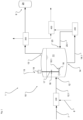
- the entire plant 1 for the catalytic production of diesel oil 9 from the starting material 7 is shown schematically as a block diagram.
- the starting material 7 is fed via the inlet system 100 to the reaction unit 10, which has at least one reactor, but can also comprise two or more reactors connected in parallel (not shown).
- the starting material 7 is fed into the reactor 11 via the reactor inlet 12, as shown.
- the process and auxiliary materials 8, such as carrier oil to be added, lime and catalyst, are also introduced via the introduction system 100. Alternatively, but not shown, this can be done via a separate feed unit that is connected to the reactor via a pipeline, with a separate access nozzle being provided in the reactor for this purpose.
- a product preparation stage 300 for the diesel oil 9 is connected via a pipeline to or to the head space 11.1 of the reactor 11 via the head outlet 13. In the product preparation stage 300, the diesel oil portion is separated from the lower-boiling aqueous phase in the gas and vapor phase.
- the diesel oil 9 is stored in the storage tank 24.
- the reactor 11 is connected via the bottom outlet 14 and the outlet line 14.1 to a sediment processing stage 200, from which the return line 23.1 leads into the return inlet 23 so that a liquid phase can be fed back into the reactor 11.
- the system 1 also comprises a coupling and purification unit 400, which is optional and by means of which the diesel oil 9 can be desulfurized, for example, and/or the solid and sedimentation substances can be further processed and packaged.
- the product processing stage 300 and/or the sediment processing stage are connected to one another in a suitable manner via suitable conveying means and/or lines.
- the reactor 11 has a stirring unit 15 with a drive 19, a drive shaft 17, a stirring body 16 and a cutting unit 18.
- the stirring body 16 is designed as a 2- to 4-bladed propeller in this and the following embodiments.
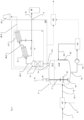
- the Figure 2 shows Appendix 1 acc. Figure 1 in an embodiment in which the product preparation stage 300 for the gas and/or vapor phase leaving the headspace of the reactor 11 via the head outlet 13 comprises a separation and deposition unit 3, which includes a deposition column 4 and two condensers 5.1, 5.2 connected in series, which are connected via the steam lines 26.1 and 26.2. These condensers 5.1, 5.2 are operated at a temperature just above the boiling point of water at > 100°C, ideally in a temperature range of 101°C to 105°C. This process control enables the volatile vapor phase, which essentially contains remaining water vapor, to leave the product preparation stage 300 to the chimney 25 via the steam line 26.3.
- a separation and deposition unit 3 which includes a deposition column 4 and two condensers 5.1, 5.2 connected in series, which are connected via the steam lines 26.1 and 26.2.
- These condensers 5.1, 5.2 are operated at a temperature just above the boiling point of water at > 100°C, ideally in
- the condensed diesel oil 9 leaves the respective condenser 5.1, 5.2 via the product lines 27.1 and 27.2 and is fed to the storage tank 24 via the collecting product line 27. Starting from one of the product lines 27, 27.1, 27.2, diesel oil 9 is fed to the top of the separation column 4 via the return line 28 in order to ensure a reliable separation process.
- the separation column 4 is filled with a bed 4.1 of inert shaped pieces, usually metallic shaped bodies, which are arranged on one or more sieve plates. In this case, a proportion of diesel oil of less than 15% of the total flow is returned to the separation column 4.
- the separation column 4 essentially does not serve as a distillation column, but rather serves the purpose of safely retaining entrained foreign or starting materials, rising foam and heavy oil droplets in the reactor 11.
- the heating device 22 an SSG high-frequency wave heater, is shown schematically on the reactor 11 in the area of the product space 11.2, whereby, as stated above, usual power and/or data lines, fittings, valves, conveyors, etc. are not shown.
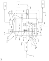
- the drive shaft 17 of the agitator 15 is arranged at the distance E1 parallel and eccentric to the central axis MA of the reactor 11 and is held by the fastening flange 19.1 on the upper dished bottom 30.1.
- the cutting device 18 has a diameter d1 which is slightly larger than the diameters d2 of the two agitator bodies 16.1 and 16.2, which are attached above and below the cutting device 18 on the same drive shaft 17 and are driven by it.
- the distance between the upper edge or flange of the lower dished bottom 30.2 to the lower edge or flange of the upper dished bottom 30.1 is the height H1.
- the height H2 is also measured up to the lower edge or flange of the upper dished bottom 30.1, but has the deepest extension of the lower dished bottom 30.2 as the lower reference point.
- the flange of the reactor inlet 12 is inclined upwards by the angle ⁇ of 30° with respect to the horizontal 29.2, with the horizontal 29.2 penetrating the opening at the reactor inlet 12 in the center of the flow area.
- the horizontal 29.2 thus forms a theoretical center line that runs parallel and centrally between an upper plane e1, which at the height h1 includes the highest point of the upper edge of the reactor inlet 12, and a lower plane e2, which at the height h2 includes the lowest point of the lower edge of the reactor inlet 12.
- the reactor inlet 12 and the return inlet 23 are formed in such a way that a line or a conveyor unit can be directly flanged on, in particular that the housing of an introductory Conveyor screw is held and sealed thereon (not shown).
- Known flange or coupling elements can be provided for this purpose. It is particularly advantageous if there is no longer a separate pipe section between the reactor inlet and the outlet end of the incoming conveyor screw and these merge directly into one another.
- the return inlet 23 is also inclined by an angle ⁇ to the horizontal, which should be in the range of 5° to 35°.
- the space spanned by the cutting unit 18 during rotation lies below the horizontal 29.1 or encompasses it and ideally lies below the plane e2.
- a theoretical cutting plane 31 as a theoretical middle plane of the space that results from the rotational movement of the cutting unit 18, lies at a height h3 that is smaller than the height h1 and in particular is also smaller than or equal to the height h2.
- the motor power of the drive 19 is in the range of 9 to 15 kW motor with a speed of 1,300 to 2,000 rpm. Depending on the gear, a drive speed of 400 to 500 rpm is achieved on the stirring body 16 in the present embodiment.
- the separating column 4 is attached to the top outlet 13 via a connecting flange directly to the upper dished bottom 30.1 on the reactor 11.
- the heating device is in the design according to Figure 3 a SSG high frequency wave heater 22.1, with an output of 100 kW, whose High frequency waves 22.2, indicated as cubic waves, act directly on the mixing phase.
- the SSG high frequency wave heater 22.1 is arranged in the interior of the reactor 11.
- SSG high-frequency wave heater 22.1 (not shown) is in the head space 11.1 of the reactor 11, because this reduces the thermal-mechanical influences and provides better accessibility in the event of maintenance.
- the actual solid-state amplifier of the high-frequency wave heater comprises 2, 3 or 4 LDMOS on one or both sides of the conductor track, each with a power of 200 to 500 W, i.e. it is equipped with a maximum of 8 LDMOS.
- the output power is therefore 50 to 400 kW, depending on the number of LDMOS in the central solid-state amplifier. Common parts and components, as well as the necessary power supply, are not listed here for the sake of clarity.
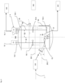
- the stirring unit 15 shown on the left essentially corresponds to the one shown in Figure 3 , with a stirring body 16.1 being provided on one drive shaft 17 and above the cutting mechanism 18. Furthermore, a second stirring device 15.1 with its own drive 21 and associated drive shaft 20 is provided, on which two further stirring bodies 16.3, 16.4 are arranged.
- the advantage is that the upward flow is supported and the drive 19 of the stirring device 15 can be made smaller.
- a further advantage is that even if one stirring device 15, 15.1 fails, the circulation in the reactor 11 can be maintained, if necessary with reduced or switched off supply of starting material.
- the second stirring device 15.1 is also arranged eccentrically by the distance E2, parallel to the central axis MA. Ideally, the two drive shafts and the central axis MA are in a vertical plane. The main flow direction is indicated by arrows.
- the embodiments and arrangements according to the Figures 3 and 4 can be combined depending on the reactor dimensions, in particular the number of stirring elements and/or the cutting edges or cutting sections.
- the second or a further Agitator may also be provided with a cutting or cutting section (not shown).
- the SSG high-frequency wave heater 22.1 comprises a signal generator 37, a solid-state generator 35, a waveguide 38 and a safety lock 36, which adjoins the reactor 11 with a first end and the safety disk 36.2 arranged there.
- a further safety pane 36.4 is arranged at the second end of the safety lock 36; both safety panes 36.2, 36.4 are made of glass or quartz glass.
- Signal generator 37 generates the high-frequency waves, which are indicated as a strong arrow pointing in the direction of the reactor 11.
- the known other elements of the SSG high-frequency wave heating such as a tuner for minimizing the reflected high-frequency waves, which are indicated as a narrow arrow, a circulator, a water load or a suitable absorption component, as well as suitable detectors and a directional coupler.
- the product space 11.2 is bordered not only by a single glass or quartz glass pane 36.2, but also by a safety lock 36, whereby in a simplified design only a single safety pane 36.2 can be provided between the product space 11.2 of the reactor 11 and the SSG high-frequency wave heater 22.1.
- Figure 6 shows Figure 6 an alternative design in which the mixed phase filled in the product chamber 11.2 is not heated directly.
- a line 58 is provided which leads in a circuit out of the reactor and back in and in which a conveying means 59, such as a double spindle pump, operates.
- a section of the line 58 is provided with a glass or quartz glass tube 39, via which the high-frequency waves from two SSG high-frequency wave heaters 22.1a, 22.1b act on the flowing mixed phase.
- the pipeline 58 has SSG high-frequency wave heaters 22.1a, 22.1b in two designs.
- the SSG high-frequency wave heater 22.1a arranged closer to the reactor 11 is constructed as in Figure 6 described, wherein the SSG high-frequency wave heater 22.1b arranged downstream for this purpose does not comprise a safety lock and only one or more windows made of glass or quartz glass are provided through which the high-frequency waves are guided into the interior of the pipe.
- a seal made of a copper material is provided on at least one side, ideally on both sides, as the sealing material for the first safety disk 36.2, which borders on the pipe interior and/or product space 11.2 that carries the mixing phase.
- a fluororubber is provided on the second side of the safety channel 36 facing away from this to seal the inside of the safety disk and a cooling flange made of an aluminum material is provided on the outside facing the semiconductor high-frequency generator.
- the units can be provided individually or jointly as explained above, in particular with regard to the type, design and/or arrangement of the SSG high-frequency wave heater 22.1.
Landscapes
- Chemical & Material Sciences (AREA)
- Engineering & Computer Science (AREA)
- Oil, Petroleum & Natural Gas (AREA)
- Life Sciences & Earth Sciences (AREA)
- Wood Science & Technology (AREA)
- Chemical Kinetics & Catalysis (AREA)
- General Chemical & Material Sciences (AREA)
- Organic Chemistry (AREA)
- Physical Or Chemical Processes And Apparatus (AREA)
Description
Die Erfindung bezieht sich auf eine Anlage zur katalytischen Herstellung von Dieselöl aus Reststoffen, wie Kunsstoffen (PE, PP, PET, PVC, etc.), cellulosehaltige Stoffen und Biomaterialien gemäß Oberbegriff des Anspruchs 1. Weiterhin bezieht sich die Erfindung auf ein entsprechendes Verfahren nach Oberbegriff des Anspruches 12.The invention relates to a plant for the catalytic production of diesel oil from residual materials, such as plastics (PE, PP, PET, PVC, etc.), cellulose-containing materials and biomaterials according to the preamble of
Aus der
Aus der
Aus der
Die Aufgabe der Erfindung ist somit, eine Anlage und ein Verfahren bereit zu stellen, dass leichter betrieben werden kann und eine geringere Störungsanfälligkeit zeigt.The object of the invention is therefore to provide a system and a method that can be operated more easily and is less susceptible to faults.
Diese Aufgabe wird durch eine Anlage nach Anspruch 1 gelöst, die dadurch geprägt ist, dass der zentrale Reaktor, der den Ausgangsstoff in einem Trägeröl aufnimmt und in welchem die katalytische Reaktion erfolgt, mindestens eine Heizung vorgesehen ist, die als Hochfrequenzwellenheizung mit einem Solid-State-Generator ausgebildet ist (SSG-Hochfrequenzwellenheizung).. Ein entsprechendes Verfahren ist gemäß Anspruch 12 beschrieben.This object is achieved by a system according to
Als Ausgangsstoff sollen vorliegend alle kohlenwasserstoffhaltigen Roh- und Reststoffe gelten, insbesondere Rest- und Abfallmaterialien aus der Gruppe der Kunsstoffen (PE, PP, PET, PVC, etc.), cellulosehaltigen Stoffen und Biomaterialien, wie Holz, Säge- oder Holzspähne, Papier, Karton, Pflanzenteile und dergleichen. Weiterhin soll unter einer granularen Partikelgröße rieselfähige Partikel verstanden werden, die in ihrer größten räumlichen Erstreckung im Mittel kleiner oder gleich 20mm aufweisen, vorteilhafterweise kleiner oder gleich 10mm aufweisen. Idealerweise sind diese als Spähne, Flakes oder vergleichbare flache Partikel ausgebildet. Vorliegend soll unter Diesel oder Dieselöl eine Kerosinmischung verstanden werden, die so genannten Mitteldestillatfraktionen bei bekannten Fraktionierungen von Erdöl. Das Trägeröl hingegen ist ein tiefersiedendes Schweröl oder Schwerölgemisch. Derartige Trägeröle sind in der Regel Thermoöle, welche bei sich hohen Betriebstemperaturen, wie vorliegend beispielsweise in dem Bereich von 280°C bis 320°C, nicht zersetzen. Weiterhin können sogenannte Zweitraffinate verwendet werden. Diese sind Öle, die nicht zu chemischen Reaktionen, einem Ausgasen oder Schaumbildung führen.In this case, all hydrocarbon-containing raw and residual materials are to be considered as starting materials, in particular residual and waste materials from the group of plastics (PE, PP, PET, PVC, etc.), cellulose-containing materials and biomaterials, such as wood, sawdust or wood shavings, paper, cardboard, plant parts and the like. Furthermore, a granular particle size is to be understood as free-flowing particles which, in their largest spatial extent, have an average of less than or equal to 20 mm, advantageously less than or equal to 10 mm. Ideally, these are formed as chips, flakes or comparable flat particles. In this case, diesel or diesel oil is to be understood as a kerosene mixture, the so-called middle distillate fractions in known fractionations of crude oil. The carrier oil, on the other hand, is a low-boiling heavy oil or heavy oil mixture. Such carrier oils are usually thermal oils which do not decompose at high operating temperatures, such as in the present case, for example, in the range of 280°C to 320°C. Furthermore, so-called secondary raffinates can be used. These are oils that do not lead to chemical reactions, outgassing or foaming.
Diese Anlage zur katalytischen Herstellung von Dieselöl aus dem vorgenannten Ausgangsstoff, umfasst ein Einleitsystem für den Ausgangsstoff, eine Reaktionseinheit, mindestens eine ein- oder mehrteilige Trenn- und Abscheideeinheit und mindestens eine Sedimentaufbereitungsstufe für Feststoffe und/oder Sedimente, u.a. wie Aschen, Teerstoffe, u.dgl.. Dabei umfasst die Reaktionseinheit in der Regel nur einen zentralen Reaktor zur Behandlung einer Mischphase aus einer flüssigen Trägerphase (Trägeröl) und dem festen Ausgangsstoff, wobei der Reaktor häufig auch Schmelzreaktor genannt wird, weil in diesem die Feststoffe katalytisch in ein Dieselöl umgewandelt werden. Der Reaktor weist idealerweise nur einen Reaktorinnenraum auf, und hat aber im bestimmunggemäßen Betrieb einen gas- oder dampfgefüllten Kopfraum und einen mit der Mischphase gefüllten Produktraum. Weiterhin umfasst er mind. einen Einlass für den Ausgangsstoff, mindestens einen Kopfauslass für eine Gas- oder Dampfphase an den sich unmittelbar eine Abscheidekolonne anschließen kann oder hieran angebracht sein kann. Weiterhin ist ein Auslass vorhanden, der mit der Sedimentaufbereitungsstufe verbunden ist, sowie mindestens ein motorisch angetriebenes Rühraggregat zur Homogenisierung und Umwälzung des Reaktorinhaltes, welches mit mindestens einem Rührkörper in den Produktraum ragt.This plant for the catalytic production of diesel oil from the aforementioned starting material comprises an inlet system for the starting material, a reaction unit, at least one single or multi-part separation and separating unit and at least one sediment treatment stage for solids and/or sediments, such as ash, tar substances, etc. The reaction unit generally comprises only one central reactor for treating a mixed phase consisting of a liquid carrier phase (carrier oil) and the solid starting material, whereby the reactor is often also called a melt reactor because the solids are catalytically converted into diesel oil in it. The reactor ideally has only one reactor interior, but in normal operation has a head space filled with gas or vapor and a product space filled with the mixed phase. It also comprises at least one inlet for the starting material, at least one head outlet for a gas or vapor phase, to which a separation column can be directly connected or attached. Furthermore, there is an outlet which is connected to the sediment treatment stage, as well as at least one motor-driven stirring unit for homogenizing and circulating the reactor contents, which protrudes into the product space with at least one stirring body.
Kern der Erfindung ist es, dass eine Heizeinrichtung für die Mischphase vorgesehen, welche als außen an der Reaktorwand anliegende Einrichtung vorgesehen ist und durch die Behälterwand hindurch auf das Fluid wirkt, alternativ kann im Reaktor eine solche Heizeinrichtung umfasst sein. Diese Heizeinrichtungen sind so ausgelegt und dimensioniert, dass eine Erwärmung einer eingefüllten Mischphase auf über 200 °C erfolgen kann, idalerweise auf eine Temperatur zwischen 280 °C und 320°C. Dabei kommt erfindungsgemäß als Heizeinrichtung eine SSG-Hochfrequenzwellenheizung zum Einsatz, die nachstehend noch näher beschrieben wird.The core of the invention is that a heating device is provided for the mixing phase, which is provided as a device on the outside of the reactor wall and acts on the fluid through the container wall; alternatively, such a heating device can be included in the reactor. These heating devices are designed and dimensioned in such a way that a filled mixing phase can be heated to over 200 °C, ideally to a temperature between 280 °C and 320 °C. According to the invention, an SSG high-frequency wave heater is used as the heating device, which is described in more detail below.
Die Heizung umfasst einen Solid-State-Generator für elektromagnetische Wellen im Bereich der Hochfrequenzwellen. Die Frequenzen liegen im Bereich von 0,9 bis 300 GHz und einer Wellenlänge von ca. 30 cm bis 1 mm. Industriell eingesetzte Hochfrequenzwellen sind üblicherweise 915 MHz, 2450 MHz und 5,8 GHz. Der so genannte Solid-State-Generator weist sich dabei dadurch aus, dass die Hochfrequenz nicht durch einen Hohlkammerresonator (Magnetron), sondern durch Halbleiterbausteine erzeugt wird. Das Magnetron ist eine Elektronenröhre mit Elektroden in einem gasgefüllten Glaskolben. Der sogenannte Solid-State-Halbleiter ersetzt die Elektronenröhren.The heater includes a solid-state generator for electromagnetic waves in the high-frequency range. The frequencies are in the range of 0.9 to 300 GHz and a wavelength of approx. 30 cm to 1 mm. High-frequency waves used industrially are usually 915 MHz, 2450 MHz and 5.8 GHz. The so-called solid-state generator is characterized by the fact that the high frequency is not generated by a hollow chamber resonator (magnetron), but by semiconductor components. The magnetron is an electron tube with electrodes in a gas-filled glass bulb. The so-called solid-state semiconductor replaces the electron tubes.
Als besondere Vorteile haben sich gezeigt, dass der alterungsbedingte Leistungsverlust eines Magnetrons bei Solid-State-Generatoren nicht vorhanden. Ein Magnetron verliert innerhalb von drei bis vier Jahren bis zu 30% seiner Ausgangleistung und muss somit regelmäßig ersetzt oder gewartet werden, wenn die Leistung auf einem guten Niveau gehalten werden soll. Halbleiterkomponenten hingegen sind für eine Lebensdauer von über 10 Jahren bis zu 20 Jahren im kontinuierlichen Betrieb ausgelegt. Weiterhin besteht ein Vorteil darin, dass die Hochspannung von bis zu 4 kV, die ein Magnetron zur Frequenzerzeugung benötigt, bei Solid-State-Generatoren nicht notwendig ist. Solid-State-Generatoren arbeiten mit Gleichspannungen ab 28 V. Damit sind die Komponenten wie Schwingungsquelle (Oszillator), Trafos, und Lüfter für die jeweilige Leistungsklasse deutlich keiner. Der Solid-State-Generator selbst ist damit ebenfalls bezogen auf die äußeren Abmessungen kleiner und somit ist die gesamte Hochfrequenzwellenheizung raumsparender ausbildbar. Die Hochfrequenzwelle weist somit eine höhere Effizienz und längere Lebensdauer auf und führen zu geringeren Betriebskosten.One particular advantage has been shown to be that the age-related loss of performance of a magnetron does not occur with solid-state generators. A magnetron loses up to 30% of its output power within three to four years and must therefore be regularly replaced or serviced if the performance is to be maintained at a good level. Semiconductor components, on the other hand, are designed for a service life of over 10 years to 20 years in continuous operation. Another advantage is that the high voltage of up to 4 kV that a magnetron needs to generate frequencies is not necessary with solid-state generators. Solid-state generators work with direct voltages from 28 V. This means that components such as the oscillation source (oscillator), transformers and fans are significantly smaller for the respective performance class. The solid-state generator itself is also smaller in terms of its external dimensions and the entire high-frequency wave heating system can therefore be designed to save space. The high-frequency wave is therefore more efficient and has a longer service life and leads to lower operating costs.
Die emittierte Hochfrequenz wird von dem Solid-State-Generator über Hohlleiter in den Reaktorinnenraum geleitet, wo das Thermoöl mit dem Ausgangsstoff und den Zusatzstoffen durch die beschriebene Wechselwirkung erhitzt werden.The emitted high frequency is guided from the solid-state generator via waveguides into the reactor interior, where the thermal oil with the starting material and the additives are heated by the described interaction.
Die Hohlleiter sind Aluminium-Hohl-Profile, in der Regel rechteckige Hohl-Profile, die aus geraden Stücken und Bögen vielseitige Anordnungen von Reaktoren und Solid-State- - Generator ermöglichen. Die elektromagnetischen Wellen (Hochfrequenzwelle) wirken auf die Moleküle und bringen diese in Schwingung und/oder Rotation. Damit erhöht sich die kinetische Energie und somit die Temperatur des Fluids.The waveguides are hollow aluminum profiles, usually rectangular hollow profiles, which allow versatile arrangements of reactors and solid-state generators from straight pieces and curves. The electromagnetic waves (high frequency waves) act on the molecules and cause them to vibrate and/or rotate. This increases the kinetic energy and thus the temperature of the fluid.
Diese hat einen sehr hohen Wirkungsgrad und an den Austauschflächen bzw. den aussendenden Oberflächen der SSG-Hochfrequenzwellenheizung erfolgt nicht, wie bei konventionellen Heizoberflächen, eine thermisch bedingte Anhaftung aufgrund lokaler Überhitzung. Mindestens eine solche SSG-Hochfrequenzwellenheizung ist idealerweise im flüssigkeitsüberdecken Raum des Reaktorinnenraumes angeordnet. Die Leistung des Solid-State Schwingungsgenerators sollte im Bereich von über 70kW liegen, idealerweise im Bereich von 80kW bis 250kW. Bedarfsweise kann die Leistung auch darüber liegen oder mehr als ein Solid-State-Schwingungsgenerator vorgesehen werden.This has a very high level of efficiency and, unlike conventional heating surfaces, there is no thermal adhesion due to local overheating on the exchange surfaces or the emitting surfaces of the SSG high-frequency wave heater. At least one such SSG high-frequency wave heater is ideally arranged in the liquid-covered space of the reactor interior. The output of the solid-state vibration generator should be in the range of over 70 kW, ideally in the range of 80 kW to 250 kW. If necessary, the output can also be higher or more than one solid-state vibration generator can be provided.
Die SSG-Hochfrequenzwellenheizung umfasst dabei als Hauptkomponenten in vorgenannter Weise kein Magnetron, sondern einen Generator, der wiederum im Wesentlichen aus Halbleiterbausteinen (Solid-State) und einen Hohlleiter besteht. Eingangsseitig umfasst die SSG-Hochfrequenzwellenheizung einen bestromten Signalgenerator (Oszillator), der eine Ausgangsstärke im mW-Bereich hat. Die Schwingungsquelle des Signalgenerators kann beispielsweise ein geeignet angeregter Schwingquarz, Kristall oder eine vergleichbarer Schwingungsquelle sein. Vor dem eigentlichen Solid-State-Verstärker kann ein Zwischenverstärker für das Schwingungssignal vorgesehen sein, der wiederum eigenständig bestromt sein kann, bspw. im Bereich von 30 bis 70 V. Hieran schließt sich der eigentliche Solid-State-Verstärker/-Generator an, mit den zur Leiterbahn ein- oder beidseitig angeordneten Transistoren, insbesondere LDMOS (laterally-diffused metal-oxide semiconductor). Vor dem ableitenden Hohlleiter ist ein Zirkulator für richtungsfalsche Leistung angeordnet. Der genannte Hohlleiter umfasst in der Regel unter anderem mindestens eine zum Produktraum angrenzende und abtrennende Glas- oder Quarzglasscheibe, einen Tuner zur Minimierung der reflektierten Wellen, einen Zirkulator und eine Wasserlast (Absorptionskomponente) sowie geeignete Detektoren und Richtkoppler. Bei einer verbesserten Ausführungsform grenzt an den Produktraum nicht nur ein Glas- oder Quarzglasscheibe, sondern eine Sicherheitsschleuse mit beidseitigem Abschluss durch eine Glas- oder Quarzglasscheibe, wobei deren Innenraum mit einem Inertgas gefüllt werden oder durch den ein Inertgas strömen kann. Dabei ist unter beidseitig die Richtung der Haupterstreckung des Hohlleiters zu verstehen, in welchem die Hochfrequenzwellen geführt werden. Der Vorteil besteht darin, dass der Innenraum evakuierbar ist und im Falle von Beschädigung der an den Produktraum angrenzenden Scheibe, kein Sauerstoff in den Reaktor gelangt und weiterhin die sonstigen Komponenten der SSG-Hochfrequenzwellenheizung geschützt bleiben.The SSG high-frequency wave heater does not comprise a magnetron as the main component as mentioned above, but rather a generator, which in turn essentially consists of semiconductor components (solid-state) and a waveguide. On the input side, the SSG high-frequency wave heater comprises a powered signal generator (oscillator) which has an output strength in the mW range. The oscillation source of the signal generator can be, for example, a suitably excited quartz crystal, crystal or a comparable oscillation source. An intermediate amplifier for the oscillation signal can be provided in front of the actual solid-state amplifier, which in turn can be powered independently, for example in the range of 30 to 70 V. This is followed by the actual solid-state amplifier/generator, with the transistors arranged on one or both sides of the conductor track, in particular LDMOS (laterally-diffused metal-oxide semiconductor). A circulator for wrong-direction power is arranged in front of the dissipating waveguide. The waveguide mentioned generally comprises, among other things, at least one glass or Quartz glass pane, a tuner to minimize the reflected waves, a circulator and a water load (absorption component) as well as suitable detectors and directional couplers. In an improved embodiment, the product space is bordered not only by a glass or quartz glass pane, but also by a safety lock with a glass or quartz glass pane on both sides, the interior of which can be filled with an inert gas or through which an inert gas can flow. Both sides is understood to mean the direction of the main extension of the waveguide in which the high-frequency waves are guided. The advantage is that the interior can be evacuated and if the pane adjacent to the product space is damaged, no oxygen gets into the reactor and the other components of the SSG high-frequency wave heater remain protected.
Eine Alternative Bauform besteht darin, dass nicht der Reaktorinhalt unmittelbar durch vorstehend genannte Scheibe in der Reaktorwand oder einem Befestigungsstutzen mittels SSG-Hochfrequenzwellenheizung erwärmt wird, sondern die mindestens eine SSG-Hochfrequenzwellenheizung durch ein Glas- oder Quarzglasrohr auf einen Seitenstrom der Mischphase einwirkt. Dieser Seitenstrom in einer Umlaufleitung wird vorteilhafterweise von einem geeigneten Fördermittel angetrieben, wie beispielsweise einer Doppelschneckenpumpe.An alternative design is that the reactor contents are not heated directly by the above-mentioned disk in the reactor wall or a mounting nozzle using SSG high-frequency wave heating, but the at least one SSG high-frequency wave heating acts on a side stream of the mixed phase through a glass or quartz glass tube. This side stream in a circulation line is advantageously driven by a suitable conveying means, such as a twin-screw pump.
Zur Dichtung der Sicherheitsscheiben der Sicherheitsschleuse im Hohlkanal werden vorteilhafterweise Papierdichtungen oder Dichtungen aus eine Kupfermaterial (Weichkupfer) vorgesehen, so dass eine gasdichte Trennung hergestellt ist. Es hat sich überraschenderweise herausgestellt, dass diese gasdichte Strecke vom zentralen Reaktor als sehr vorteilhafte Abkühlungsstrecke fungiert.To seal the safety panes of the safety lock in the hollow channel, paper seals or seals made of a copper material (soft copper) are advantageously provided so that a gas-tight separation is created. Surprisingly, it has been found that this gas-tight section from the central reactor functions as a very advantageous cooling section.
Bei einer alternativen Variante wird die SSG-Hochfrequenzwellenheizung im Deckel und/oder Kopfraum des Reaktors angeordnet. Der Vorteil besteht drin, dass durch die Lage der SSG-Hochfrequenzwellenheizung im Kopfraum des Reaktors die thermischen und mechanischen Einflüsse verringert werden. Weiterhin ist so eine gute Zugänglichkeit im Wartungsfalle gegeben.In an alternative variant, the SSG high-frequency wave heater is arranged in the lid and/or head space of the reactor. The advantage is that the thermal and mechanical influences are reduced by the location of the SSG high-frequency wave heater in the head space of the reactor. Furthermore, this ensures good accessibility in the event of maintenance.
Besonders bevorzugt ist weiterhin, mindestens ein motorisch rotativ angetriebenes Schneidwerk zur schlagenden und/oder schneidenden Zerkleinerung des Ausgangsstoffes vorgesehen, welches mindestens eine Schneide oder einen Schneidabschnitt aufweist und in den Produktraum des Reaktors hinein ragt.Furthermore, it is particularly preferred to provide at least one motor-driven, rotationally driven cutting device for the impact and/or cutting comminution of the starting material, which has at least one cutting edge or one cutting section and projects into the product space of the reactor.
Bei einer Ausführungsform des Schneidwerkes ist dieses an derselben Antriebswelle angebracht und von dieser angetrieben, wie der mindestens eine Rührkörper, wobei alternativ oder zusätzlich auch der mindestens eine Rührkörper als Schneide oder mit einem Schneidabschnitt ausgebildet sein kann. Eine weitere Alternative besteht darin, dass das Schneidwerk in den Produktraum hineinragt und eine eigene Antriebswelle und einen eigenen vom Antrieb des Rühraggregats unabhängigen Antrieb aufweist.In one embodiment of the cutting device, it is attached to and driven by the same drive shaft as the at least one stirring body, whereby alternatively or additionally the at least one stirring body can also be designed as a cutting edge or with a cutting section. Another alternative is that the cutting device extends into the product space and has its own drive shaft and its own drive that is independent of the drive of the stirring unit.
Eine Verbesserung besteht darin, dass mindestens ein Rührkörper in vertikaler Höhenlage zwischen zwei Schneidwerken angeordnet ist, so dass diese unmittelbar ober- und unterhalb des Rührwerkes in der gerichteten Strömung schneidend und/oder zerteilend arbeiten können.One improvement consists in that at least one agitator body is arranged at a vertical height between two cutting units, so that they can work in a cutting and/or dividing manner directly above and below the agitator in the directed flow.
Der Antrieb muss dabei derart ausgelegt sein, dass er eine permanente vollständige Durchmischung und vielfache Umwälzung pro Minute ermöglicht, wozu er eine Geschwindigkeit des Rühraggregates von mindestens 400 bis 500 U/min ermöglichen muss. Vorteilhafterweise wird eine Umdrehungsgeschwindigkeit von 440 bis 470 U/min vorgenommen. Dabei ist es vorteilhaft, wenn die Umfangsgeschwindigkeit des Rühraggregats im Bereich von 10 bis 20 m/s liegt, und idealerweise eine Umfangsgeschwindigkeit von 13 bis 18 m/s mittels des Antriebes erreichbar und im Betrieb der Anlage eingestellt werden kann. Für den Antrieb des Schneidwerkes gilt analog, dass eine Geschwindigkeit von mindestens 400 bis 500 U/min vorliegen sollte, wobei vorteilhafterweise eine Geschwindigkeit von über 440 bis 470 U/min beim Betrieb aufrecht gehalten werden sollte.The drive must be designed in such a way that it enables permanent, complete mixing and multiple circulations per minute, which means that the stirring unit must be able to rotate at a speed of at least 400 to 500 rpm. A rotational speed of 440 to 470 rpm is advantageous. It is advantageous if the peripheral speed of the stirring unit is in the range of 10 to 20 m/s, and ideally a peripheral speed of 13 to 18 m/s can be achieved using the drive and adjusted during operation of the system. The same applies to the drive of the cutting unit, which should have a speed of at least 400 to 500 rpm, although a speed of over 440 to 470 rpm should be maintained during operation.
Eine weitere Verbesserung besteht darin, dass das Rührwerk, insb. dessen Antriebswelle im Reaktor exzentrisch angeordnet ist, wodurch sich eine besonders vorteilhafte dreidimensionale Strömung im Produktraum des Reaktors einstellt. Dabei hat sich eine Achsexzentrizität E des der Rührorganachse zur Mittelachse des Reaktors als vorteilhaft herausgestellt, die im Bereich von 0,15 bis 0,25 liegt.A further improvement is that the agitator, in particular its drive shaft, is arranged eccentrically in the reactor, which creates a particularly advantageous three-dimensional flow in the product space of the reactor. Axial eccentricity E of the agitator axis to the central axis of the reactor has proven to be advantageous, which lies in the range of 0.15 to 0.25.
Die stromabwärts dem Reaktor nachgeschaltete ein- oder mehrteilige Trenn- und Abscheideeinheit umfasst mindestens einen Kondensator und/oder eine Trennkolonne zur Abtrennung des Dieselöls. Es hat sich überraschenderweise herausgesellt, dass es hinreichend ist, nach dem Reaktor - ggf. unmittelbar auf diesem, eine einfache Abscheidekolonne vorzusehen, um nachfolgend hierzu ein oder zwei Kondensatoren vorzusehen zur Abscheidung des Produktöls.The single or multi-part separation and separation unit downstream of the reactor comprises at least one condenser and/or a separation column for separating the diesel oil. Surprisingly, it has been found that it is sufficient to provide a simple separation column after the reactor - possibly directly on top of it - in order to subsequently provide one or two condensers for separating the product oil.
Wie angedeutet, bildet dann die Abscheidekolonne mit dem Reaktor eine Baueinheit und ist direkt am Kopfraum angebracht oder über einen Flasch unmittelbar mit diesem verbunden. Dabei erstreckt sich der Kopfraum des Reaktors unmittelbar in den untersten Boden- oder Einlaufbereich der Kolonne und bildet einen einzigen Raum.As indicated, the separation column then forms a structural unit with the reactor and is attached directly to the head space or is directly connected to it via a flange. The head space of the reactor extends directly into the lowest bottom or inlet area of the column and forms a single space.
Weiterhin besteht eine verbesserte Variante darin, dass ein Rückführungseinlass am Reaktor vorgesehen ist, der mit der Sedimentaufbereitungsstufe verbunden ist und über welchen Teilströme oder Teilmengen, die über einen Auslass entnommen wurden, in den Reaktor zurückgeführt werden können. Die rückgeführten Teilströme oder Teilmengen sind in der Regel flüssig und abgereichert an Feststoffen, wie Kalk, Katalysator, Asche oder Teeranteile.A further improved variant consists in providing a recirculation inlet on the reactor, which is connected to the sediment treatment stage and via which partial flows or partial quantities that have been removed via an outlet can be returned to the reactor. The returned partial flows or partial quantities are usually liquid and depleted of solids such as lime, catalyst, ash or tar fractions.
Der Reaktoreinlass und/oder der Rückführungseinlass sind derart ausgeformt, dass ein Gehäuse einer einleitenden Förderschnecke hieran gehalten und abgedichtet ist. Hierzu können bekannte Flansch- oder Kupplungselemente vorgesehen werden. Es ist insbesondere vorteilhaft, wenn zwischen dem Reaktoreinlass und dem Auslassende der einleitenden Förderschnecke kein separates Rohrstück mehr vorhanden ist.The reactor inlet and/or the return inlet are shaped in such a way that a housing of an incoming conveyor screw is held and sealed thereon. Known flange or coupling elements can be provided for this purpose. It is particularly advantageous if there is no longer a separate pipe section between the reactor inlet and the outlet end of the incoming conveyor screw.
Dabei besteht eine Verbesserung darin, dass das Gehäuse der einleitenden Förderschnecke unmittelbar am Reaktor mit dem Auslassende endet bzw. den Reaktorflansch bildet.One improvement is that the housing of the incoming conveyor screw ends directly at the reactor with the outlet end or forms the reactor flange.
Prozess- und Hilfsstoffe, wie ein zu ergänzendes Trägeröl, Kalk, Katalysator können in eine der sonstigen Zuführungs- oder Rückführungsströme eingeleitet werden. Vorteilhafterweise ist aber eine separate Zuführungseinheit für Prozess- und Hilfsstoffe vorgesehen, die leitungsmäßig mit dem Reaktor verbunden ist, wobei hierfür ein eigener Zugangsstutzen im Reaktor vorgesehen ist.Process and auxiliary materials, such as a carrier oil to be supplemented, lime, catalyst can be introduced into one of the other feed or return streams. However, a separate feed unit for process and auxiliary materials is advantageously provided, which is connected to the reactor via a pipe, with a separate access nozzle being provided for this purpose in the reactor.
Nicht im Einzelnen beschrieben, weil für den Fachmann fachüblich, sind nötige Leitungsverbindungen, Verbindungsflansche, Tragwerkselemte und dergleichen, sowie die bekannten und üblichen Steuerungs- und Regelungseinheiten.Not described in detail, because they are common practice for a specialist, are necessary line connections, connecting flanges, structural elements and the like, as well as the known and usual control and regulation units.
Unter Nutzung dieser Anlage und insbesondere des Reaktors, ist somit ein Verfahren zur kontinuierlichen Herstellung von Dieselöl aus dem vorgenannten Ausgangsstoff möglich, welcher als granulare Feststoffphase in eine flüssige Phase aus dem vorgenannten Trägeröl eingebracht und katalytisch umgeformt wird.By using this plant and in particular the reactor, a process for the continuous production of diesel oil from the aforementioned starting material is possible, which is introduced as a granular solid phase into a liquid phase of the aforementioned carrier oil and catalytically converted.
Hierbei ist die Temperatur in der Mischphase zwischen 200 und 400°C, und liegt idalerweise zwischen 280°C und 350°C. Die Mischphase umfasst weiterhin einen Anteil an Kalk von 1,5 Gew.% bis 10 Gew.%, wobei Kalk hier als Sammelbegriff für Calcium- oder calciumcarbonathaltige Stoffe oder Stoffmischungen zu verstehen ist. Weiterhin umfasst die Mischphase einen Katalysator in einem Anteil von 1 Gew.% bis 15 Gew. %.The temperature in the mixing phase is between 200 and 400°C, and is ideally between 280°C and 350°C. The mixing phase also contains a proportion of lime of 1.5% to 10% by weight, whereby lime is understood here as a collective term for substances or mixtures of substances containing calcium or calcium carbonate. The mixing phase also contains a catalyst in a proportion of 1% to 15% by weight.
Die gas- oder dampfförmige Phase wird kontinuierlich abgeführt, idealerweise mittels mind. einer Vakuumpumpe kontinuierlich aus dem Kopfraum des Reaktors abgezogen. Stromabwärts des Reaktors wird in mind. einem Kondensator das Dieselöl von der leichterflüchtigen gas- oder dampfförmigen Phase abgetrennt. Dabei wird parallel in der Mischphase der enthaltende garanulare Ausgangsstoff mittels der mindestens einen Schneide oder dem Schneidabschnitt mechanisch zerschnitten und/oder zerkleinert wird. Zur optimalen Durchmischung im Reaktorinnenraum und zur Vermeidung von jeglicher Sedimentation, beträgt die Umfangsgeschwindigkeit des Rühraggregates zwischen 8 bis 20 m/s, wobei es sich heraus gestellt hat, dass diese idealerweise zwischen 13 bis 17 m/s liegen sollte.The gaseous or vaporous phase is continuously removed, ideally by means of at least one vacuum pump from the head space of the reactor. Downstream of the reactor, the diesel oil is separated from the more volatile gaseous or vaporous phase in at least one condenser. In parallel, in the mixing phase, the contained gaseous starting material is mechanically cut and/or crushed using at least one cutting edge or cutting section. For optimal mixing in the reactor interior and to avoid any sedimentation, the peripheral speed of the stirring unit is between 8 and 20 m/s, although it has been found that this should ideally be between 13 and 17 m/s.
Der Katalysator ist vorteilhafterweise ein Bentonith oder Zeolith, insb. ein Aluminium Silicat, der einen pulverförmigen Zustand aufweist. Der im Kopfraum des Reaktors einzustellende Druck ist kleiner oder gleich 1 bar ist, idealerweise liegt er im Bereich von 25 bis 60 mbar.The catalyst is advantageously a bentonite or zeolite, especially an aluminum silicate, which is in a powdery state. The pressure to be set in the head space of the reactor is less than or equal to 1 bar, ideally it is in the range of 25 to 60 mbar.
Nicht im Einzelnen beschrieben, weil für den Fachmann fachüblich, sind nötige Leitungsverbindungen, Verbindungsflansche, Tragwerkselemte und dergleichen, sowie die bekannten und üblichen Steuerungs- und Regelungseinheiten.Not described in detail, because they are common practice for a specialist, are necessary line connections, connecting flanges, structural elements and the like, as well as the known and usual control and regulation units.
Nachstehend wird die Erfindung beispielhaft näher erläutert, dabei zeigt
-
Figur 1 -
Figur 2 dieAnlage nach Figur 1 mit Einzelschritten zur Produktaufbereitungsstufe, -
Figur 3 ein erstes Ausführungsbeispiel des zentralen Reaktors, -
Figur 4 -
Figur 5 den Aufbau der SSG-Hochfrequenzwellenheizung des zentralen Reaktors und -
Figur 6 eine alternative Ausführungsform zurFigur 5 .
-
Figure 1 as a block diagram a process flow and the most important process steps, -
Figure 2 the system afterFigure 1 with individual steps to the product preparation stage, -
Figure 3 a first embodiment of the central reactor, -
Figure 4 a second embodiment of the central reactor, -
Figure 5 the construction of the SSG high-frequency wave heating of the central reactor and -
Figure 6 an alternative embodiment toFigure 5 .
In der
Über das Einleitsystem 100 werden auch die Prozess- und Hilfsstoffe 8, wie bspw. zu ergänzendes Trägeröl, Kalk und Katalysator eingeleitet. Alternativ, aber nicht dargestellt, kann dies über eine separate Zuführungseinheit erfolgen, die leitungsmäßig mit dem Reaktor verbunden ist, wobei hierfür ein eigener Zugangsstutzen im Reaktor vorgesehen ist. Weiterhin ist eine Produktaufbereitungsstufe 300 für das Dieselöl 9 leitungsmäßig mit oder an dem Kopfraum 11.1 des Reaktors 11 über den Kopfauslass 13 verbunden. In der Produktaufbereitungsstufe 300 wird aus der Gas - und Dampfphase der Dieselölanteil von der leichter siedenden wässrigen Phase getrennt. Das Dieselöl 9 wird im Speichertank 24 gelagert.The process and
Bodennah mit Verbindung zum Produktraum 11.2 ist der Reaktor 11 über den Bodenauslass 14 und die Auslassleitung 14.1 mit einer Sedimentaufbereitungsstufe 200 verbunden, von der aus in den Rückführeinlass 23 die Rückführleitung 23.1 führt, so dass eine flüssige Phase in den Reaktor 11 zurück geleitet werden kann. Weiterhin umfasst die Anlage 1 eine Kopplungs- und Aufreinigungseinheit 400, welche optional ist und mittels welcher das Dieselöl 9 beispielsweise entschwefelt werde kann und/oder die Fest- und Sedimentationstoffe weiter aufbereitet und konfektioniert werden können. Zu diesem Zweck sind die Produktaufbereitungsstufe 300 und/oder die Sedimentaufbereitungsstufe in geeigneter Weise über geeignete Fördermittel und/oder Leitungen miteinander verbunden.Close to the bottom with a connection to the product chamber 11.2, the
In
Wie weiterhin in
Die
Die Abscheidekolonne 4 ist mit einer Schüttung 4.1 aus inerten Formstücken gefüllt, in der Regel metallische Formkörper, die auf einem oder mehreren Siebböden angeordnet sind. Vorliegend wird ein Anteil an Dieselöl von weniger als 15% des Gesamtstromes zur Abscheidekolonne 4 zurückgeleitet. Die Abscheidekolonne 4 dient dabei im Wesentlichen nicht als Destillationskolonne, sondern erfüllt den Zweck, dass mitgerissene Fremd- oder Ausgangsstoffe, aufsteigender Schaum und Schweröltröpfchen sicher im Reaktor 11 zurückgehalten werden.The
Weiterhin ist schematisch die Heizeinrichtung 22, eine SSG-Hochfrequenzwellenheizung, am Reaktor 11 im Bereich des Produktraumes 11.2 gezeigt, wobei, wie oben ausgeführt, übliche Strom- und/oder Datenleitungen, Armaturen, Ventile, Fördermittel usw. nicht dargestellt sind.Furthermore, the
In der
Im vorliegenden Ausführungsbeispiel sind der Reaktoreinlass 12 und der Rückführungseinlass 23 derart ausgeformt, dass eine Leitung oder ein Förderaggregat unmittelar angeflanscht werden kann, insb. dass das Gehäuse einer einleitenden Förderschnecke hieran gehalten und abgedichtet ist (nicht dargestellt). Hierzu können bekannte Flansch- oder Kupplungselemente vorgesehen werden. Es ist insbesondere vorteilhaft, wenn zwischen dem Reaktoreinlass und dem Auslassende der einleitenden Förderschnecke kein separates Rohrstück mehr vorhanden ist und diese unmittelbar ineinander übergehen. Wie in der
Es hat sich ganz allgemein herausgestellt, dass es sehr vorteilhaft ist, wenn der vom Schneidwerk 18 bei der Rotation aufgespannte Raum unterhalb der Horizontalen 29.1 liegt oder diese umfasst und idealerweise unterhalb der Ebene e2 liegt. Anders ausgedrückt, idealerweise liegt eine theoretische Schneidebene 31, als eine theoretische mittlere Ebene des Raumes, die sich bei der Rotationsbewegung des Schneidwerkes 18 ergibt, bei einer Höhe h3, die kleiner ist als die Höhe h1 und insbesondere auch kleiner oder gleich der Höhe h2 ist.In general, it has been found that it is very advantageous if the space spanned by the cutting
Es zeigte sich überraschenderweise, dass eine weitere Verbesserung darin besteht, wenn die theoretische Schneidebene 31 im Raum zwischen der Horizontalen 29.1 und der Ebene e2 liegt. Damit wird zugeführtes Ausgangsmaterial beim Eintritt in den Reaktor 11 unmittelbar schneidend und schlagend bearbeitet, wodurch eine optimale Verteilung und Zerkleinerung erfolgen.Surprisingly, it was found that a further improvement is achieved if the
Bei einem sehr ausgeprägten, stark gewölbten unteren Klöpperboden 30.2, findet die analoge Betrachtung ausgehend vom tiefsten Punkte des Klöpperbodens statt.In the case of a very pronounced, strongly curved lower dished bottom 30.2, the analogous observation takes place starting from the lowest point of the dished bottom.
Die Motorleistung des Antriebes 19 ist vorliegend im Bereich von 9 bis 15 kW Motor mit einer Drehzahl von 1.300 bis 2.000 U/min. Je nach Getriebe wird bei dem vorliegenden Ausführungsbeispiel eine Antriebsdrehzahl am Rührkörper 16 von 400 bis 500 U/min erreicht.The motor power of the
Wie in der
Eine alternative, nicht dargestellte Lage der SSG-Hochfrequenzwellenheizung 22.1 ist hierbei im Kopfraum 11.1 des Reaktors 11, weil hierdurch zum einen die thermischmechanischen Einflüsse verringert werden und eine bessere Zugänglichkeit im Wartungsfalle gegeben ist.An alternative location of the SSG high-frequency wave heater 22.1 (not shown) is in the head space 11.1 of the
Im vorliegenden Beispiel umfasst der eigentliche Solid-State-Verstärker der Hochfrequenzwellenheizung ein- oder beidseitig der Leiterbahn je 2, 3 oder 4 LDMOS mit einer jeweiligen Leistung von 200 bis 500 W, ist also maximal mit 8 LDMOS ausgestattet.In the present example, the actual solid-state amplifier of the high-frequency wave heater comprises 2, 3 or 4 LDMOS on one or both sides of the conductor track, each with a power of 200 to 500 W, i.e. it is equipped with a maximum of 8 LDMOS.
Die Ausgangsleitung beträgt somit je nach Anzahl der LDMOS im zentralen Solid-State-Verstärker 50 bis 400 kW. Übliche Bauteile und Komponenten, sowie nötige Spannungsversorgung sind hier der Übersichtlichkeit nicht aufgeführt.The output power is therefore 50 to 400 kW, depending on the number of LDMOS in the central solid-state amplifier. Common parts and components, as well as the necessary power supply, are not listed here for the sake of clarity.
In der Ausführungsvariante gem. der
Die Ausführungsformen und Anordnungen nach den
In den
Die SSG-Hochfrequenzwellenheizung 22.1 umfasst einen Signalgenerator 37, einen Solid-State-Generator 35 einen Hohlleiter 38 und eine Sicherheitsschleuse 36 auf, die mit einem ersten Ende und er dort angeordneten Sicherheitsscheibe 36.2 an den Reaktor 11 angrenzt.The SSG high-frequency wave heater 22.1 comprises a
Übliche Flansch- und Verbindungselemente sind vorgesehen, aber nicht weiter ausgeführt. In den Innenraum 36.1 der Sicherheitsschleuse 36 kann über den Einlass 36.3 ein Inertgas, bspw. Stickstoff in den Innenraum 36.1 geleitet werden. An dem zweiten Ende der Sicherheitsschleuse 36 ist eine weitere Sicherheitsscheibe 36.4 angeordnet, beide Sicherheitsscheiben 36.2, 36.4 sind aus einem Glas- oder Quarzglas. Signalgenerator 37 erzeugt die Hochfrequenzwellen, die als kräftiger Pfeil, der in Richtung des Reaktors 11 weist, angedeutet sind. Nur erwähnt, ohne detaillierte Darstellung, sind die bekannten sonstigen Elemente der SSG-Hochfrequenzwellenheizung, wie ein Tuner zur Minimierung der reflektierten Hochfrequenzwellen, die als schmaler Pfeil angedeutet sind, ein Zirkulator, eine Wasserlast oder eine geeignete Absorptionskomponente, sowie geeignete Detektoren und ein Richtkoppler.Conventional flange and connecting elements are provided, but not further developed. An inert gas, e.g. nitrogen, can be fed into the interior 36.1 of the
Bei dieser vorteilhaften Ausführungsform grenzt an den Produktraum 11.2 nicht nur ein einzelne Glas- oder Quarzglasscheibe 36.2, sondern eine Sicherheitsschleuse 36, wobei bei einer vereinfachten Bauart auch nur eine einzige Sicherheitsscheibe 36.2 zwischen Produktraum 11.2 des Reaktors 11 und der SSG-Hochfrequenzwellenheizung 22.1 vorgesehen werden kann.In this advantageous embodiment, the product space 11.2 is bordered not only by a single glass or quartz glass pane 36.2, but also by a
Alternativ zur
Bei der gezeigten Variante weist die Rohrleitung 58 SSG-Hochfrequenzwellenheizungen 22.1a, 22.1b in zwei Bauarten auf. Die näher am Reaktor 11 angeordnete SSG-Hochfrequenzwellenheizung 22.1a ist aufgebaut, wie in
Als vorteilhaft hat sich herausgestellt, wenn beispielsweise als Dichtungsmaterial für die erste Sicherheitsscheibe 36.2, die an den die Mischphase führenden Rohrinnenraum und/oder Produktraum 11.2 grenzt, mindestens einseitig eine Dichtung aus einem Kupfermaterial vorgesehen wird, idealerweise beidseitig. Auf der zweiten, der hiervon abgewandten Seite des Sicherheitskanals 36 ist zur Dichtung der Innenseite der Sicherheitsscheibe ein Fluorkautschuk und auf der zum Halbleiter-Hochfrequenz-Generator weisenden Außenseite ein Kühlflansch aus einem Aluminiumwerkstoff vorgesehen.It has been found to be advantageous if, for example, a seal made of a copper material is provided on at least one side, ideally on both sides, as the sealing material for the first safety disk 36.2, which borders on the pipe interior and/or product space 11.2 that carries the mixing phase. On the second side of the
Die teilweise nicht dargestellten Aggregate können wie vorstehend ausgeführt einzeln oder gemeinschaftlich vorgesehen werden, insb. Bauart, Bauform und/oder die Anordnung der SSG-Hochfrequenzwellenheizung 22.1 betreffend.The units, some of which are not shown, can be provided individually or jointly as explained above, in particular with regard to the type, design and/or arrangement of the SSG high-frequency wave heater 22.1.
- 11
- AnlageAttachment
- 22
- Zuführung von Hilfsstoffensupply of auxiliary materials
- 33
- Trenn- und Abscheideeinheitseparation and separation unit
- 44
-
Abscheidekolonne
4.1 Schüttungseparation column
4.1 Filling - 55
-
Kondensatoren
5.1 Kondensator
5.2 Kondensatorcapacitors
5.1 capacitor
5.2 Capacitor - 66
- Inertgasinert gas
- 77
- Ausgangsstoffstarting material
- 88
-
Hilfs- und Prozessmedien
8.1 Tank
8.2 Fördermitelauxiliary and process media
8.1 Tank
8.2 Funding - 99
- Dieselöl/-leitungdiesel oil/line
- 1010
- Reaktoreinheitreactor unit
- 1111
-
Reaktor
11.1 Kopfraum
11.2 Produktraumreactor
11.1 Headroom
11.2 Product space - 1212
-
Reaktoreinlass
12.1 Einlassleitungreactor inlet
12.1 Inlet line - 1313
- Kopfauslasshead outlet
- 1414
-
Bodenauslass
14.1 Auslassleitungfloor outlet
14.1 Outlet line - 1515
- Rühraggregatstirring unit
- 1616
-
Rührkörper
16.1 Rührkörper erster
16.2 Rührkörper zweiterstirring elements
16.1 Stirring body first
16.2 Stirring body second - 1717
-
Antriebswelle
17.1 Antriebdrive shaft
17.1 Drive - 1818
-
Schneidwerk
18.1 Schneide oder Schneidabschnittcutting unit
18.1 Cutting edge or cutting section - 1919
-
Antrieb
19.1 Befestigungsflanschdrive
19.1 Mounting flange - 2020
- Antriebswelledrive shaft
- 2121
- Antriebdrive
- 2222
-
Heizeinrichtung
22.1 SSG-Hochfrequenzwellenheizung
22.2 Hochfrequenzwelleheating device
22.1 SSG high frequency wave heating
22.2 High-frequency wave - 2323
-
Rückführungseinlass
23.1 Rückführungsleitungreturn inlet
23.1 Return line - 2424
- Speichertankstorage tank
- 2525
- KaminChimney
- 2626
- Dampfleitung 26.1, 26.2, 26.3steam line 26.1, 26.2, 26.3
- 2727
- Produktleitung 27.1, 27.2Product Line 27.1, 27.2
- 2828
- Rückleitungreturn line
- 2929
-
Horizontale
29.1 Mitte von H1
29.2 Mitte von H2 ...horizontal
29.1 Middle of H1
29.2 Middle of H2 ... - 3030
-
Klöpperboden
30.1 oberer Klöpperboden
30.2 unterer Klöpperbodendished bottom
30.1 upper dished bottom
30.2 lower dished bottom - 3131
- Schneidebenecutting plane
- 3232
- Steuer- und Versorgungseinheitcontrol and supply unit
- 3434
- Daten- und/oder Energieleitungdata and/or power line
- 3535
- Solid-State-Generatorsolid-state generator
- 3636
-
Sicherheitsschleuse
36.1 Innenraum
36.2 Sicherheitsglas
36.3 Einlass
36.4 Sicherheitsglassecurity gate
36.1 Interior
36.2 Safety glass
36.3 Inlet
36.4 Safety glass - 3737
- Signalgeneratorsignal generator
- 3838
- Hohlleiterwaveguide
- 3939
- Glas- oder Quarzglasrohrglass or quartz glass tube
- 5858
- LeitungLine
- 5959
- Fördermittelfunding
- 100100
- Einleitsysteminlet system
- 200200
- Sedimentaufbereitungsstufe (Sediment) (neu)sediment processing stage (sediment) (new)
- 300300
- Produktaufbereitungsstufe (Produkt) (neu)Product preparation stage (product) (new)
- 400400
- Kopplungs- und Aufreinigungseinheitcoupling and purification unit
- e1e1
- Ebene, horizontalplane, horizontal
- e2e2
- Ebene, horizontalplane, horizontal
- E1E1
- Exzentrizitäteccentricity
- E2E2
- Exzentrizitäteccentricity
- H1H1
- Höhe Reaktorinnenraum ohne KlöpperbodenHeight of reactor interior without dished bottom
- H2H2
- Höhe Reaktorinnenraum mit unterer KlöpperbodenHeight of reactor interior with lower dished bottom
- h1h1
- Höhe der Oberkante des Einlassesheight of the upper edge of the inlet
- h2h2
- Höhe der Unterkante des Einlassesheight of the lower edge of the inlet
- h3h3
- Höhe des Schneidwerkesheight of the cutting unit
- α, βα, β
- Winkelangle
- MAMA
- Mittelachsecentral axis
Claims (15)
- System (1) for the catalytic production of diesel oil (9) from a starting material (7) from the group of residues, such as plastics (PE, PP, pet, PVC, etc.), cellulose-containing substances and biomaterials, comprising at least one introduction system (100) for the starting material (7), a reaction unit (10), at least one single-part or multi-part separation and separator unit (3) and at least one sediment preparation stage (200) for solids and/or sediments, wherein the reaction unit (10) comprises at least one reactor (11) for treating a mixing phase of a liquid carrier phase (carrier oil) and the solid starting material (7), wherein the reactor (11)- in intended operation, has a gas- or steam-filled head chamber (11.1) and a product chamber (11.2) filled with the mixing phase, further comprising an inlet (12) for the starting material (7), a head outlet (13) for a gas or vapor phase, an outlet (14) connected to the sediment preparation stage (200) and at least one motor-driven agitation unit (15) for homogenizing and circulating the reactor content, which projects into the product chamber (11.2) with at least one agitator body (16), characterized in that the reactor (11) comprises at least one heating device (22) or a heating device (22) directly adjacent thereto, wherein the heating device (22) is an SSG high-frequency wave heater (22.1), which has a solid-state generator (35), and the at least one SSG high-frequency wave heater (22.1) has in particular a power of 80 to 200 kW or more, and which is separated from the product chamber (11.2) of the reactor (11) or the circulating line (58) carrying the mixing phase by at least one pane, window and/or pipe made of glass or quartz glass.
- System (1) according to Claim 1, characterized in that the at least one SSG high-frequency wave heater (22.1) comprises a safety lock (36) as a waveguide section, which has an evacuatable inner chamber (36.1), in particular an inner chamber (36.1), on which glass or quartz glass panes (36.2, 36.4) are arranged on both sides.
- System (1) according to any of the preceding claims, characterized in that the reactor (11) furthermore has at least one motor-driven rotary cutting mechanism (18) for impact and/or cutting comminution of the starting material (7), wherein optionally- it can be provided that the at least one cutting mechanism (18) has at least one cutting edge or a cutting section (18.1) and is attached to and driven by the same drive shaft (17) as the at least one agitator body (16) and/or that the at least one agitator body (16) is designed as a cutting edge or with a cutting section (18.1);- it can be provided that the cutting mechanism (18) has a drive shaft (20) and its own drive (21) independent of the drive (19) of the agitation unit (15); or- it can be provided that at least one cutting mechanism (18) is arranged at a vertical height between two agitator bodies (16.1, 16.2).
- System (1) according to any of the preceding claims, characterized in that- the drive (19) enables the speed of the agitation unit (15) of at least 400 to 500 rpm, advantageously a rotational speed of 440 to 470 rpm and/or a circumferential speed of the agitation unit (15) of 10 to 20 m/s can be achieved, ideally a circumferential speed of 13 to 18 m/s can be achieved;
and/or- the agitator (15) and/or its drive shaft (17) is arranged eccentrically in the reactor (9). - System (1) according to Claim 3, characterized in that the drive (21) of the cutting mechanism (18) allows a speed of at least 400 to 500 rpm, advantageously allows a speed of over 440 to 470 rpm.
- System (1) according to any of the preceding claims, characterized in that the single- or multi-part separation and separator unit (3) comprises at least one condenser (5) and/or a separating column (4) for separating the diesel oil (9) .
- System (1) according to any of the preceding claims, characterized in that- the separating column (4) and subsequently the at least one condenser (5), ideally two condensers (5.1, 5.2), are arranged downstream of the reactor (11);
and/or- the separating column (4) forms a structural unit with the reactor (11) and is attached directly to or connected to the head chamber (11.1). - System (1) according to any of the preceding claims, characterized in that a recirculation inlet (23) is provided on the reactor (11), which is connected to the sediment preparation stage (200) and via which partial streams or partial quantities removed via the outlet (14) can be recirculated to the reactor (11).
- System (1) according to any of the preceding claims, characterized in that the reactor inlet (12) and/or the return inlet (23) is shaped in such a way that a housing (42.1, 62.1) of an introducing screw conveyor (42, 62) is held and sealed against it.
- System (1) according to any of the preceding claims, characterized in that the housing (42.1, 62.1) of the introducing screw conveyor (42, 62) is directly connected to an inlet (12, 23) or a flange of the reactor (11) and/or projects into the latter.
- System (1) according to any of the preceding claims, characterized in that a supply unit (2) for process and auxiliary materials (8) is provided, which is connected by lines to the reactor (11).
- Method for the continuous production of diesel oil from a starting material (7) from the group of residual materials, such as plastics (PE, PP, PET, PVC, etc.), cellulose-containing substances (sawdust, shredded material) and biomaterials, which is introduced as a granular solid phase into a liquid phase from a carrier oil and catalytically shaped, characterized in that a system (1) according to any of the preceding Claims 1 to 11 is provided, and wherein- the temperature in the mixing phase is between 200 and 400°C, ideally between 280°C and 350°C, and- the mixing phase still contains a proportion of lime of 1.5% by weight to 10% by weight (2-5) and a proportion of catalyst of 1% by weight to 15% by weight 2-10), and wherein- the gaseous or vaporous phase is continuously withdrawn from the head chamber (11.1) by means of at least one vacuum pump and, downstream of the reactor (11) in at least one condenser (5), the diesel oil (9) is separated from the highly volatile gaseous or vaporous phase.
- Method according to Claim 12, characterized in that the starting material (7) contained in the mixing phase is mechanically comminuted in the reactor (11) by means of the at least one cutting edge or the cutting section (18.1).
- Method according to any of Claims 12 or 13, characterized in that the catalyst is a bentonite or zeolite, in particular an aluminium silicate.
- Method according to any of Claims 12 to 14, characterized in that- the circumferential speed of the agitation unit (15) is between 8 and 20 m/s, ideally between 13 and 17 m/s;
and/or- the pressure in the head chamber (11.1) of the reactor (11) is less than or equal to 1 bar, ideally in the range of 25 to 60 mbar.
Applications Claiming Priority (2)
| Application Number | Priority Date | Filing Date | Title |
|---|---|---|---|
| DE102020004964.8A DE102020004964A1 (en) | 2020-08-14 | 2020-08-14 | Plant and process for the catalytic production of diesel oils from organic materials |
| PCT/EP2021/072173 WO2022034028A1 (en) | 2020-08-14 | 2021-08-09 | System and method for catalytically producing diesel oils from organic materials |
Publications (3)
| Publication Number | Publication Date |
|---|---|
| EP4196552A1 EP4196552A1 (en) | 2023-06-21 |
| EP4196552C0 EP4196552C0 (en) | 2024-10-16 |
| EP4196552B1 true EP4196552B1 (en) | 2024-10-16 |
Family
ID=77564083
Family Applications (1)
| Application Number | Title | Priority Date | Filing Date |
|---|---|---|---|
| EP21763034.2A Active EP4196552B1 (en) | 2020-08-14 | 2021-08-09 | Apparatus and process for the catalytic production of diesel from organic materials |
Country Status (5)
| Country | Link |
|---|---|
| EP (1) | EP4196552B1 (en) |
| DE (1) | DE102020004964A1 (en) |
| ES (1) | ES2994313T3 (en) |
| PL (1) | PL4196552T3 (en) |
| WO (1) | WO2022034028A1 (en) |
Family Cites Families (13)
| Publication number | Priority date | Publication date | Assignee | Title |
|---|---|---|---|---|
| DE10049377C2 (en) * | 2000-10-05 | 2002-10-31 | Evk Dr Oberlaender Gmbh & Co K | Catalytic generation of diesel oil and petrol from hydrocarbon-containing waste and oils |
| DE10316696A1 (en) | 2003-04-10 | 2004-10-28 | Herbert Kannegiesser Gmbh | Wash and spin drum of top loading horizontal axis clothes washing has sliding loading door on inside of drum wall which is automatically opened and closed |
| DE10316969A1 (en) | 2003-04-14 | 2004-12-02 | Jochen Herrlinger | Process and device for the catalytic treatment of residues in continuously cleaned and heated tube bundle reactors |
| DE10356245B4 (en) | 2003-12-02 | 2007-01-25 | Alphakat Gmbh | Process for the production of diesel oil from hydrocarbon-containing residues and an apparatus for carrying out this process |
| WO2005071043A1 (en) | 2004-01-24 | 2005-08-04 | Nill Tech Gmbh | Device and method for recovering fractional hydrocarbons from recycled plastic fractions and/or from oily residues |
| WO2009154485A1 (en) | 2008-06-20 | 2009-12-23 | Turney Christian Stewart Macgr | Apparatus and method for processing organic material |
| EP2300565A4 (en) * | 2008-07-11 | 2014-09-17 | Fuel Ltd P | PROCESS FOR TREATING OIL REFINING WASTE |
| KR101162612B1 (en) * | 2011-11-30 | 2012-07-04 | 이엔에프씨 주식회사 | Oil production system from waste material and catalyst therefor |
| DE102012010763A1 (en) * | 2012-03-26 | 2013-09-26 | Axel Trautmann | Apparatus and method for the catalytic depolymerization of carbon-containing material |
| WO2015026945A1 (en) * | 2013-08-20 | 2015-02-26 | H Quest Partners, LP | Method for processing hydrocarbon fuels using microwave energy |
| US20170101584A1 (en) | 2015-10-13 | 2017-04-13 | H Quest Partners, LP | Wave modes for the microwave induced conversion of coal |
| FR3061492B1 (en) * | 2017-01-03 | 2019-05-24 | D.M.S | PROCESS FOR PRODUCTION OF FUEL BY CATALYTIC CRACKING OF A SOLID HYDROCARBON MATERIAL AND DEVICE FOR IMPLEMENTING SAID METHOD |
| DE102019001696A1 (en) | 2019-03-11 | 2020-09-17 | Olaf Heimbürge | Plant and process for the catalytic production of diesel oils from organic materials |
-
2020
- 2020-08-14 DE DE102020004964.8A patent/DE102020004964A1/en not_active Withdrawn
-
2021
- 2021-08-09 PL PL21763034.2T patent/PL4196552T3/en unknown
- 2021-08-09 WO PCT/EP2021/072173 patent/WO2022034028A1/en not_active Ceased
- 2021-08-09 ES ES21763034T patent/ES2994313T3/en active Active
- 2021-08-09 EP EP21763034.2A patent/EP4196552B1/en active Active
Also Published As
| Publication number | Publication date |
|---|---|
| WO2022034028A1 (en) | 2022-02-17 |
| EP4196552A1 (en) | 2023-06-21 |
| EP4196552C0 (en) | 2024-10-16 |
| DE102020004964A1 (en) | 2022-02-17 |
| ES2994313T3 (en) | 2025-01-21 |
| PL4196552T3 (en) | 2025-03-24 |
Similar Documents
| Publication | Publication Date | Title |
|---|---|---|
| US8691053B2 (en) | Method for processing domestic and industrial organic waste | |
| DE10356245B4 (en) | Process for the production of diesel oil from hydrocarbon-containing residues and an apparatus for carrying out this process | |
| DE2951617C2 (en) | Process and system for processing polyurethane | |
| EP2831198B1 (en) | Device and method for the catalytic depolymerisation of material containing hydrocarbon | |
| DE19631201C2 (en) | Process and reactor for converting biomass into liquid, solid or gaseous fuels and chemical raw materials | |
| KR20110090952A (en) | Material treatment method | |
| EP2130893A2 (en) | Method for producing coal, in particular coal slurry | |
| EP2484434B1 (en) | Continuous hydrothermal carbonization reactor | |
| EP4196552B1 (en) | Apparatus and process for the catalytic production of diesel from organic materials | |
| WO2020182338A1 (en) | System and method for catalytically producing diesel oils from organic materials | |
| EP4605135A1 (en) | Device for comminuting and/or processing material, assembly, method, fibre material and use of the fibre material | |
| EP3938468A1 (en) | System and method for catalytically producing diesel oil from organic materials | |
| WO2020182336A1 (en) | System and method for catalytically producing diesel oils from organic materials | |
| DE19732080B4 (en) | Process and device for the continuous degradation of organic substances | |
| EP2280776A2 (en) | Device, method and use of a reactor for producing starting materials, combustible substances and fuels from organic substances | |
| EP1884563A1 (en) | Device for creating a suspension from biomass | |
| CN102513333B (en) | Solid garbage residue stirring, discharging and crushing machine | |
| EP3745065B1 (en) | Reactor for producing water vapour and dry substance | |
| EP1884564A1 (en) | Preparation of liquid manure and organic solids for a fermentation | |
| DE102012022710B4 (en) | Method and device for the decentralized mobile refurbishment of crude oil, coal, green waste and processed refuse to middle distillates and low-sulfur, anhydrous incandescent coal with mixed turbines | |
| EP4056632B1 (en) | Method and system for the depolymerisation of synthetic material | |
| DE102022132971A1 (en) | Device for crushing and/or processing material, arrangement and method | |
| CN121016640A (en) | A device and method for treating organic waste by subcritical hydrothermal decomposition | |
| WO2024260504A1 (en) | Biogas plant for production of biogas and fermentation product | |
| EP2909288A2 (en) | Method and device for converting organic secondary raw materials into oil mist |
Legal Events
| Date | Code | Title | Description |
|---|---|---|---|
| STAA | Information on the status of an ep patent application or granted ep patent |
Free format text: STATUS: UNKNOWN |
|
| STAA | Information on the status of an ep patent application or granted ep patent |
Free format text: STATUS: THE INTERNATIONAL PUBLICATION HAS BEEN MADE |
|
| PUAI | Public reference made under article 153(3) epc to a published international application that has entered the european phase |
Free format text: ORIGINAL CODE: 0009012 |
|
| STAA | Information on the status of an ep patent application or granted ep patent |
Free format text: STATUS: REQUEST FOR EXAMINATION WAS MADE |
|
| 17P | Request for examination filed |
Effective date: 20230213 |
|
| AK | Designated contracting states |
Kind code of ref document: A1 Designated state(s): AL AT BE BG CH CY CZ DE DK EE ES FI FR GB GR HR HU IE IS IT LI LT LU LV MC MK MT NL NO PL PT RO RS SE SI SK SM TR |
|
| DAV | Request for validation of the european patent (deleted) | ||
| DAX | Request for extension of the european patent (deleted) | ||
| GRAP | Despatch of communication of intention to grant a patent |
Free format text: ORIGINAL CODE: EPIDOSNIGR1 |
|
| STAA | Information on the status of an ep patent application or granted ep patent |
Free format text: STATUS: GRANT OF PATENT IS INTENDED |
|
| RIC1 | Information provided on ipc code assigned before grant |
Ipc: C10G 1/10 20060101AFI20240626BHEP |
|
| INTG | Intention to grant announced |
Effective date: 20240705 |
|
| GRAS | Grant fee paid |
Free format text: ORIGINAL CODE: EPIDOSNIGR3 |
|
| GRAA | (expected) grant |
Free format text: ORIGINAL CODE: 0009210 |
|
| STAA | Information on the status of an ep patent application or granted ep patent |
Free format text: STATUS: THE PATENT HAS BEEN GRANTED |
|
| AK | Designated contracting states |
Kind code of ref document: B1 Designated state(s): AL AT BE BG CH CY CZ DE DK EE ES FI FR GB GR HR HU IE IS IT LI LT LU LV MC MK MT NL NO PL PT RO RS SE SI SK SM TR |
|
| REG | Reference to a national code |
Ref country code: GB Ref legal event code: FG4D Free format text: NOT ENGLISH |
|
| REG | Reference to a national code |
Ref country code: DE Ref legal event code: R096 Ref document number: 502021005525 Country of ref document: DE Ref country code: CH Ref legal event code: EP |
|
| REG | Reference to a national code |
Ref country code: IE Ref legal event code: FG4D Free format text: LANGUAGE OF EP DOCUMENT: GERMAN |
|
| U01 | Request for unitary effect filed |
Effective date: 20241016 |
|
| U07 | Unitary effect registered |
Designated state(s): AT BE BG DE DK EE FI FR IT LT LU LV MT NL PT RO SE SI Effective date: 20241022 |
|
| REG | Reference to a national code |
Ref country code: ES Ref legal event code: FG2A Ref document number: 2994313 Country of ref document: ES Kind code of ref document: T3 Effective date: 20250121 |
|
| PG25 | Lapsed in a contracting state [announced via postgrant information from national office to epo] |
Ref country code: IS Free format text: LAPSE BECAUSE OF FAILURE TO SUBMIT A TRANSLATION OF THE DESCRIPTION OR TO PAY THE FEE WITHIN THE PRESCRIBED TIME-LIMIT Effective date: 20250216 Ref country code: HR Free format text: LAPSE BECAUSE OF FAILURE TO SUBMIT A TRANSLATION OF THE DESCRIPTION OR TO PAY THE FEE WITHIN THE PRESCRIBED TIME-LIMIT Effective date: 20241016 |
|
| PG25 | Lapsed in a contracting state [announced via postgrant information from national office to epo] |
Ref country code: GR Free format text: LAPSE BECAUSE OF FAILURE TO SUBMIT A TRANSLATION OF THE DESCRIPTION OR TO PAY THE FEE WITHIN THE PRESCRIBED TIME-LIMIT Effective date: 20250117 |
|
| PG25 | Lapsed in a contracting state [announced via postgrant information from national office to epo] |
Ref country code: RS Free format text: LAPSE BECAUSE OF FAILURE TO SUBMIT A TRANSLATION OF THE DESCRIPTION OR TO PAY THE FEE WITHIN THE PRESCRIBED TIME-LIMIT Effective date: 20250116 |
|
| PG25 | Lapsed in a contracting state [announced via postgrant information from national office to epo] |
Ref country code: SM Free format text: LAPSE BECAUSE OF FAILURE TO SUBMIT A TRANSLATION OF THE DESCRIPTION OR TO PAY THE FEE WITHIN THE PRESCRIBED TIME-LIMIT Effective date: 20241016 |
|
| PG25 | Lapsed in a contracting state [announced via postgrant information from national office to epo] |
Ref country code: SK Free format text: LAPSE BECAUSE OF FAILURE TO SUBMIT A TRANSLATION OF THE DESCRIPTION OR TO PAY THE FEE WITHIN THE PRESCRIBED TIME-LIMIT Effective date: 20241016 |
|
| PG25 | Lapsed in a contracting state [announced via postgrant information from national office to epo] |
Ref country code: CZ Free format text: LAPSE BECAUSE OF FAILURE TO SUBMIT A TRANSLATION OF THE DESCRIPTION OR TO PAY THE FEE WITHIN THE PRESCRIBED TIME-LIMIT Effective date: 20241016 |
|
| PLBE | No opposition filed within time limit |
Free format text: ORIGINAL CODE: 0009261 |
|
| STAA | Information on the status of an ep patent application or granted ep patent |
Free format text: STATUS: NO OPPOSITION FILED WITHIN TIME LIMIT |
|
| 26N | No opposition filed |
Effective date: 20250717 |
|
| U20 | Renewal fee for the european patent with unitary effect paid |
Year of fee payment: 5 Effective date: 20250826 |
|
| PGFP | Annual fee paid to national office [announced via postgrant information from national office to epo] |
Ref country code: ES Payment date: 20250917 Year of fee payment: 5 |
|
| PGFP | Annual fee paid to national office [announced via postgrant information from national office to epo] |
Ref country code: NO Payment date: 20250820 Year of fee payment: 5 |
|
| PGFP | Annual fee paid to national office [announced via postgrant information from national office to epo] |
Ref country code: PL Payment date: 20250728 Year of fee payment: 5 |
|
| PGFP | Annual fee paid to national office [announced via postgrant information from national office to epo] |
Ref country code: CH Payment date: 20250901 Year of fee payment: 5 |
|
| REG | Reference to a national code |
Ref country code: CH Ref legal event code: R18 Free format text: ST27 STATUS EVENT CODE: U-0-0-R10-R18 (AS PROVIDED BY THE NATIONAL OFFICE) Effective date: 20251105 |