EP4196552B1 - Appareil et procédé de production catalytique de diesel à partir de matières organiques - Google Patents
Appareil et procédé de production catalytique de diesel à partir de matières organiques Download PDFInfo
- Publication number
- EP4196552B1 EP4196552B1 EP21763034.2A EP21763034A EP4196552B1 EP 4196552 B1 EP4196552 B1 EP 4196552B1 EP 21763034 A EP21763034 A EP 21763034A EP 4196552 B1 EP4196552 B1 EP 4196552B1
- Authority
- EP
- European Patent Office
- Prior art keywords
- reactor
- phase
- cutting
- starting material
- unit
- Prior art date
- Legal status (The legal status is an assumption and is not a legal conclusion. Google has not performed a legal analysis and makes no representation as to the accuracy of the status listed.)
- Active
Links
Images


Classifications
-
- C—CHEMISTRY; METALLURGY
- C10—PETROLEUM, GAS OR COKE INDUSTRIES; TECHNICAL GASES CONTAINING CARBON MONOXIDE; FUELS; LUBRICANTS; PEAT
- C10G—CRACKING HYDROCARBON OILS; PRODUCTION OF LIQUID HYDROCARBON MIXTURES, e.g. BY DESTRUCTIVE HYDROGENATION, OLIGOMERISATION, POLYMERISATION; RECOVERY OF HYDROCARBON OILS FROM OIL-SHALE, OIL-SAND, OR GASES; REFINING MIXTURES MAINLY CONSISTING OF HYDROCARBONS; REFORMING OF NAPHTHA; MINERAL WAXES
- C10G1/00—Production of liquid hydrocarbon mixtures from oil-shale, oil-sand, or non-melting solid carbonaceous or similar materials, e.g. wood, coal
- C10G1/10—Production of liquid hydrocarbon mixtures from oil-shale, oil-sand, or non-melting solid carbonaceous or similar materials, e.g. wood, coal from rubber or rubber waste
Definitions
- the invention relates to a plant for the catalytic production of diesel oil from residual materials, such as plastics (PE, PP, PET, PVC, etc.), cellulose-containing materials and biomaterials according to the preamble of claim 1. Furthermore, the invention relates to a corresponding process according to the preamble of claim 12.
- From the US 2019/0330537 A1 A process for producing energy products is known.
- the DE 100 49 377 A1 concerns the catalytic production of diesel oil and gasoline from hydrocarbon-containing waste and oils.
- US 2013/0136665 A1 A system for producing oil from waste is known.
- From the WO 2010/003180 A1 A process for processing oil refinery waste is known.
- From the US 2015/0047962 A1 A device for the catalytic depolymerization of hydrocarbon-containing material is known.
- US 2015/0053592 A1 A process for treating hydrocarbon fuels with microwave energy is known.
- the object of the invention is therefore to provide a system and a method that can be operated more easily and is less susceptible to faults.
- a system according to claim 1 which is characterized in that the central reactor, which receives the starting material in a carrier oil and in which the catalytic reaction takes place, is provided with at least one heater which is designed as a high-frequency wave heater with a solid-state generator (SSG high-frequency wave heater).
- SSG high-frequency wave heater a solid-state generator
- hydrocarbon-containing raw and residual materials are to be considered as starting materials, in particular residual and waste materials from the group of plastics (PE, PP, PET, PVC, etc.), cellulose-containing materials and biomaterials, such as wood, sawdust or wood shavings, paper, cardboard, plant parts and the like.
- a granular particle size is to be understood as free-flowing particles which, in their largest spatial extent, have an average of less than or equal to 20 mm, advantageously less than or equal to 10 mm. Ideally, these are formed as chips, flakes or comparable flat particles.
- diesel or diesel oil is to be understood as a kerosene mixture, the so-called middle distillate fractions in known fractionations of crude oil.
- the carrier oil is a low-boiling heavy oil or heavy oil mixture.
- Such carrier oils are usually thermal oils which do not decompose at high operating temperatures, such as in the present case, for example, in the range of 280°C to 320°C.
- so-called secondary raffinates can be used. These are oils that do not lead to chemical reactions, outgassing or foaming.
- This plant for the catalytic production of diesel oil from the aforementioned starting material comprises an inlet system for the starting material, a reaction unit, at least one single or multi-part separation and separating unit and at least one sediment treatment stage for solids and/or sediments, such as ash, tar substances, etc.
- the reaction unit generally comprises only one central reactor for treating a mixed phase consisting of a liquid carrier phase (carrier oil) and the solid starting material, whereby the reactor is often also called a melt reactor because the solids are catalytically converted into diesel oil in it.
- the reactor ideally has only one reactor interior, but in normal operation has a head space filled with gas or vapor and a product space filled with the mixed phase.
- It also comprises at least one inlet for the starting material, at least one head outlet for a gas or vapor phase, to which a separation column can be directly connected or attached. Furthermore, there is an outlet which is connected to the sediment treatment stage, as well as at least one motor-driven stirring unit for homogenizing and circulating the reactor contents, which protrudes into the product space with at least one stirring body.
- the core of the invention is that a heating device is provided for the mixing phase, which is provided as a device on the outside of the reactor wall and acts on the fluid through the container wall; alternatively, such a heating device can be included in the reactor.
- These heating devices are designed and dimensioned in such a way that a filled mixing phase can be heated to over 200 °C, ideally to a temperature between 280 °C and 320 °C.
- an SSG high-frequency wave heater is used as the heating device, which is described in more detail below.
- the heater includes a solid-state generator for electromagnetic waves in the high-frequency range.
- the frequencies are in the range of 0.9 to 300 GHz and a wavelength of approx. 30 cm to 1 mm.
- High-frequency waves used industrially are usually 915 MHz, 2450 MHz and 5.8 GHz.
- the so-called solid-state generator is characterized by the fact that the high frequency is not generated by a hollow chamber resonator (magnetron), but by semiconductor components.
- the magnetron is an electron tube with electrodes in a gas-filled glass bulb.
- the so-called solid-state semiconductor replaces the electron tubes.
- One particular advantage has been shown to be that the age-related loss of performance of a magnetron does not occur with solid-state generators.
- a magnetron loses up to 30% of its output power within three to four years and must therefore be regularly replaced or serviced if the performance is to be maintained at a good level.
- Semiconductor components are designed for a service life of over 10 years to 20 years in continuous operation.
- Another advantage is that the high voltage of up to 4 kV that a magnetron needs to generate frequencies is not necessary with solid-state generators.
- Solid-state generators work with direct voltages from 28 V. This means that components such as the oscillation source (oscillator), transformers and fans are significantly smaller for the respective performance class.
- the solid-state generator itself is also smaller in terms of its external dimensions and the entire high-frequency wave heating system can therefore be designed to save space. The high-frequency wave is therefore more efficient and has a longer service life and leads to lower operating costs.
- the emitted high frequency is guided from the solid-state generator via waveguides into the reactor interior, where the thermal oil with the starting material and the additives are heated by the described interaction.
- the waveguides are hollow aluminum profiles, usually rectangular hollow profiles, which allow versatile arrangements of reactors and solid-state generators from straight pieces and curves.
- the electromagnetic waves (high frequency waves) act on the molecules and cause them to vibrate and/or rotate. This increases the kinetic energy and thus the temperature of the fluid.
- the output of the solid-state vibration generator should be in the range of over 70 kW, ideally in the range of 80 kW to 250 kW. If necessary, the output can also be higher or more than one solid-state vibration generator can be provided.
- the SSG high-frequency wave heater does not comprise a magnetron as the main component as mentioned above, but rather a generator, which in turn essentially consists of semiconductor components (solid-state) and a waveguide.
- the SSG high-frequency wave heater comprises a powered signal generator (oscillator) which has an output strength in the mW range.
- the oscillation source of the signal generator can be, for example, a suitably excited quartz crystal, crystal or a comparable oscillation source.
- An intermediate amplifier for the oscillation signal can be provided in front of the actual solid-state amplifier, which in turn can be powered independently, for example in the range of 30 to 70 V.
- the waveguide mentioned generally comprises, among other things, at least one glass or Quartz glass pane, a tuner to minimize the reflected waves, a circulator and a water load (absorption component) as well as suitable detectors and directional couplers.
- the product space is bordered not only by a glass or quartz glass pane, but also by a safety lock with a glass or quartz glass pane on both sides, the interior of which can be filled with an inert gas or through which an inert gas can flow. Both sides is understood to mean the direction of the main extension of the waveguide in which the high-frequency waves are guided.
- An alternative design is that the reactor contents are not heated directly by the above-mentioned disk in the reactor wall or a mounting nozzle using SSG high-frequency wave heating, but the at least one SSG high-frequency wave heating acts on a side stream of the mixed phase through a glass or quartz glass tube.
- This side stream in a circulation line is advantageously driven by a suitable conveying means, such as a twin-screw pump.
- the SSG high-frequency wave heater is arranged in the lid and/or head space of the reactor.
- the advantage is that the thermal and mechanical influences are reduced by the location of the SSG high-frequency wave heater in the head space of the reactor. Furthermore, this ensures good accessibility in the event of maintenance.
- At least one motor-driven, rotationally driven cutting device for the impact and/or cutting comminution of the starting material, which has at least one cutting edge or one cutting section and projects into the product space of the reactor.
- the cutting device is attached to and driven by the same drive shaft as the at least one stirring body, whereby alternatively or additionally the at least one stirring body can also be designed as a cutting edge or with a cutting section.
- the cutting device extends into the product space and has its own drive shaft and its own drive that is independent of the drive of the stirring unit.
- One improvement consists in that at least one agitator body is arranged at a vertical height between two cutting units, so that they can work in a cutting and/or dividing manner directly above and below the agitator in the directed flow.
- the drive must be designed in such a way that it enables permanent, complete mixing and multiple circulations per minute, which means that the stirring unit must be able to rotate at a speed of at least 400 to 500 rpm.
- a rotational speed of 440 to 470 rpm is advantageous. It is advantageous if the peripheral speed of the stirring unit is in the range of 10 to 20 m/s, and ideally a peripheral speed of 13 to 18 m/s can be achieved using the drive and adjusted during operation of the system.
- the same applies to the drive of the cutting unit which should have a speed of at least 400 to 500 rpm, although a speed of over 440 to 470 rpm should be maintained during operation.
- a further improvement is that the agitator, in particular its drive shaft, is arranged eccentrically in the reactor, which creates a particularly advantageous three-dimensional flow in the product space of the reactor.
- Axial eccentricity E of the agitator axis to the central axis of the reactor has proven to be advantageous, which lies in the range of 0.15 to 0.25.
- the single or multi-part separation and separation unit downstream of the reactor comprises at least one condenser and/or a separation column for separating the diesel oil. Surprisingly, it has been found that it is sufficient to provide a simple separation column after the reactor - possibly directly on top of it - in order to subsequently provide one or two condensers for separating the product oil.
- the separation column then forms a structural unit with the reactor and is attached directly to the head space or is directly connected to it via a flange.
- the head space of the reactor extends directly into the lowest bottom or inlet area of the column and forms a single space.
- a further improved variant consists in providing a recirculation inlet on the reactor, which is connected to the sediment treatment stage and via which partial flows or partial quantities that have been removed via an outlet can be returned to the reactor.
- the returned partial flows or partial quantities are usually liquid and depleted of solids such as lime, catalyst, ash or tar fractions.
- the reactor inlet and/or the return inlet are shaped in such a way that a housing of an incoming conveyor screw is held and sealed thereon.
- Known flange or coupling elements can be provided for this purpose. It is particularly advantageous if there is no longer a separate pipe section between the reactor inlet and the outlet end of the incoming conveyor screw.
- One improvement is that the housing of the incoming conveyor screw ends directly at the reactor with the outlet end or forms the reactor flange.
- Process and auxiliary materials such as a carrier oil to be supplemented, lime, catalyst can be introduced into one of the other feed or return streams.
- a separate feed unit for process and auxiliary materials is advantageously provided, which is connected to the reactor via a pipe, with a separate access nozzle being provided for this purpose in the reactor.
- the temperature in the mixing phase is between 200 and 400°C, and is ideally between 280°C and 350°C.
- the mixing phase also contains a proportion of lime of 1.5% to 10% by weight, whereby lime is understood here as a collective term for substances or mixtures of substances containing calcium or calcium carbonate.
- the mixing phase also contains a catalyst in a proportion of 1% to 15% by weight.
- the gaseous or vaporous phase is continuously removed, ideally by means of at least one vacuum pump from the head space of the reactor. Downstream of the reactor, the diesel oil is separated from the more volatile gaseous or vaporous phase in at least one condenser.
- the contained gaseous starting material is mechanically cut and/or crushed using at least one cutting edge or cutting section.
- the peripheral speed of the stirring unit is between 8 and 20 m/s, although it has been found that this should ideally be between 13 and 17 m/s.
- the catalyst is advantageously a bentonite or zeolite, especially an aluminum silicate, which is in a powdery state.
- the pressure to be set in the head space of the reactor is less than or equal to 1 bar, ideally it is in the range of 25 to 60 mbar.
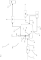
- the entire plant 1 for the catalytic production of diesel oil 9 from the starting material 7 is shown schematically as a block diagram.
- the starting material 7 is fed via the inlet system 100 to the reaction unit 10, which has at least one reactor, but can also comprise two or more reactors connected in parallel (not shown).
- the starting material 7 is fed into the reactor 11 via the reactor inlet 12, as shown.
- the process and auxiliary materials 8, such as carrier oil to be added, lime and catalyst, are also introduced via the introduction system 100. Alternatively, but not shown, this can be done via a separate feed unit that is connected to the reactor via a pipeline, with a separate access nozzle being provided in the reactor for this purpose.
- a product preparation stage 300 for the diesel oil 9 is connected via a pipeline to or to the head space 11.1 of the reactor 11 via the head outlet 13. In the product preparation stage 300, the diesel oil portion is separated from the lower-boiling aqueous phase in the gas and vapor phase.
- the diesel oil 9 is stored in the storage tank 24.
- the reactor 11 is connected via the bottom outlet 14 and the outlet line 14.1 to a sediment processing stage 200, from which the return line 23.1 leads into the return inlet 23 so that a liquid phase can be fed back into the reactor 11.
- the system 1 also comprises a coupling and purification unit 400, which is optional and by means of which the diesel oil 9 can be desulfurized, for example, and/or the solid and sedimentation substances can be further processed and packaged.
- the product processing stage 300 and/or the sediment processing stage are connected to one another in a suitable manner via suitable conveying means and/or lines.
- the reactor 11 has a stirring unit 15 with a drive 19, a drive shaft 17, a stirring body 16 and a cutting unit 18.
- the stirring body 16 is designed as a 2- to 4-bladed propeller in this and the following embodiments.
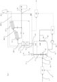
- the Figure 2 shows Appendix 1 acc. Figure 1 in an embodiment in which the product preparation stage 300 for the gas and/or vapor phase leaving the headspace of the reactor 11 via the head outlet 13 comprises a separation and deposition unit 3, which includes a deposition column 4 and two condensers 5.1, 5.2 connected in series, which are connected via the steam lines 26.1 and 26.2. These condensers 5.1, 5.2 are operated at a temperature just above the boiling point of water at > 100°C, ideally in a temperature range of 101°C to 105°C. This process control enables the volatile vapor phase, which essentially contains remaining water vapor, to leave the product preparation stage 300 to the chimney 25 via the steam line 26.3.
- a separation and deposition unit 3 which includes a deposition column 4 and two condensers 5.1, 5.2 connected in series, which are connected via the steam lines 26.1 and 26.2.
- These condensers 5.1, 5.2 are operated at a temperature just above the boiling point of water at > 100°C, ideally in
- the condensed diesel oil 9 leaves the respective condenser 5.1, 5.2 via the product lines 27.1 and 27.2 and is fed to the storage tank 24 via the collecting product line 27. Starting from one of the product lines 27, 27.1, 27.2, diesel oil 9 is fed to the top of the separation column 4 via the return line 28 in order to ensure a reliable separation process.
- the separation column 4 is filled with a bed 4.1 of inert shaped pieces, usually metallic shaped bodies, which are arranged on one or more sieve plates. In this case, a proportion of diesel oil of less than 15% of the total flow is returned to the separation column 4.
- the separation column 4 essentially does not serve as a distillation column, but rather serves the purpose of safely retaining entrained foreign or starting materials, rising foam and heavy oil droplets in the reactor 11.
- the heating device 22 an SSG high-frequency wave heater, is shown schematically on the reactor 11 in the area of the product space 11.2, whereby, as stated above, usual power and/or data lines, fittings, valves, conveyors, etc. are not shown.
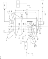
- the drive shaft 17 of the agitator 15 is arranged at the distance E1 parallel and eccentric to the central axis MA of the reactor 11 and is held by the fastening flange 19.1 on the upper dished bottom 30.1.
- the cutting device 18 has a diameter d1 which is slightly larger than the diameters d2 of the two agitator bodies 16.1 and 16.2, which are attached above and below the cutting device 18 on the same drive shaft 17 and are driven by it.
- the distance between the upper edge or flange of the lower dished bottom 30.2 to the lower edge or flange of the upper dished bottom 30.1 is the height H1.
- the height H2 is also measured up to the lower edge or flange of the upper dished bottom 30.1, but has the deepest extension of the lower dished bottom 30.2 as the lower reference point.
- the flange of the reactor inlet 12 is inclined upwards by the angle ⁇ of 30° with respect to the horizontal 29.2, with the horizontal 29.2 penetrating the opening at the reactor inlet 12 in the center of the flow area.
- the horizontal 29.2 thus forms a theoretical center line that runs parallel and centrally between an upper plane e1, which at the height h1 includes the highest point of the upper edge of the reactor inlet 12, and a lower plane e2, which at the height h2 includes the lowest point of the lower edge of the reactor inlet 12.
- the reactor inlet 12 and the return inlet 23 are formed in such a way that a line or a conveyor unit can be directly flanged on, in particular that the housing of an introductory Conveyor screw is held and sealed thereon (not shown).
- Known flange or coupling elements can be provided for this purpose. It is particularly advantageous if there is no longer a separate pipe section between the reactor inlet and the outlet end of the incoming conveyor screw and these merge directly into one another.
- the return inlet 23 is also inclined by an angle ⁇ to the horizontal, which should be in the range of 5° to 35°.
- the space spanned by the cutting unit 18 during rotation lies below the horizontal 29.1 or encompasses it and ideally lies below the plane e2.
- a theoretical cutting plane 31 as a theoretical middle plane of the space that results from the rotational movement of the cutting unit 18, lies at a height h3 that is smaller than the height h1 and in particular is also smaller than or equal to the height h2.
- the motor power of the drive 19 is in the range of 9 to 15 kW motor with a speed of 1,300 to 2,000 rpm. Depending on the gear, a drive speed of 400 to 500 rpm is achieved on the stirring body 16 in the present embodiment.
- the separating column 4 is attached to the top outlet 13 via a connecting flange directly to the upper dished bottom 30.1 on the reactor 11.
- the heating device is in the design according to Figure 3 a SSG high frequency wave heater 22.1, with an output of 100 kW, whose High frequency waves 22.2, indicated as cubic waves, act directly on the mixing phase.
- the SSG high frequency wave heater 22.1 is arranged in the interior of the reactor 11.
- SSG high-frequency wave heater 22.1 (not shown) is in the head space 11.1 of the reactor 11, because this reduces the thermal-mechanical influences and provides better accessibility in the event of maintenance.
- the actual solid-state amplifier of the high-frequency wave heater comprises 2, 3 or 4 LDMOS on one or both sides of the conductor track, each with a power of 200 to 500 W, i.e. it is equipped with a maximum of 8 LDMOS.
- the output power is therefore 50 to 400 kW, depending on the number of LDMOS in the central solid-state amplifier. Common parts and components, as well as the necessary power supply, are not listed here for the sake of clarity.
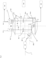
- the stirring unit 15 shown on the left essentially corresponds to the one shown in Figure 3 , with a stirring body 16.1 being provided on one drive shaft 17 and above the cutting mechanism 18. Furthermore, a second stirring device 15.1 with its own drive 21 and associated drive shaft 20 is provided, on which two further stirring bodies 16.3, 16.4 are arranged.
- the advantage is that the upward flow is supported and the drive 19 of the stirring device 15 can be made smaller.
- a further advantage is that even if one stirring device 15, 15.1 fails, the circulation in the reactor 11 can be maintained, if necessary with reduced or switched off supply of starting material.
- the second stirring device 15.1 is also arranged eccentrically by the distance E2, parallel to the central axis MA. Ideally, the two drive shafts and the central axis MA are in a vertical plane. The main flow direction is indicated by arrows.
- the embodiments and arrangements according to the Figures 3 and 4 can be combined depending on the reactor dimensions, in particular the number of stirring elements and/or the cutting edges or cutting sections.
- the second or a further Agitator may also be provided with a cutting or cutting section (not shown).
- the SSG high-frequency wave heater 22.1 comprises a signal generator 37, a solid-state generator 35, a waveguide 38 and a safety lock 36, which adjoins the reactor 11 with a first end and the safety disk 36.2 arranged there.
- a further safety pane 36.4 is arranged at the second end of the safety lock 36; both safety panes 36.2, 36.4 are made of glass or quartz glass.
- Signal generator 37 generates the high-frequency waves, which are indicated as a strong arrow pointing in the direction of the reactor 11.
- the known other elements of the SSG high-frequency wave heating such as a tuner for minimizing the reflected high-frequency waves, which are indicated as a narrow arrow, a circulator, a water load or a suitable absorption component, as well as suitable detectors and a directional coupler.
- the product space 11.2 is bordered not only by a single glass or quartz glass pane 36.2, but also by a safety lock 36, whereby in a simplified design only a single safety pane 36.2 can be provided between the product space 11.2 of the reactor 11 and the SSG high-frequency wave heater 22.1.
- Figure 6 shows Figure 6 an alternative design in which the mixed phase filled in the product chamber 11.2 is not heated directly.
- a line 58 is provided which leads in a circuit out of the reactor and back in and in which a conveying means 59, such as a double spindle pump, operates.
- a section of the line 58 is provided with a glass or quartz glass tube 39, via which the high-frequency waves from two SSG high-frequency wave heaters 22.1a, 22.1b act on the flowing mixed phase.
- the pipeline 58 has SSG high-frequency wave heaters 22.1a, 22.1b in two designs.
- the SSG high-frequency wave heater 22.1a arranged closer to the reactor 11 is constructed as in Figure 6 described, wherein the SSG high-frequency wave heater 22.1b arranged downstream for this purpose does not comprise a safety lock and only one or more windows made of glass or quartz glass are provided through which the high-frequency waves are guided into the interior of the pipe.
- a seal made of a copper material is provided on at least one side, ideally on both sides, as the sealing material for the first safety disk 36.2, which borders on the pipe interior and/or product space 11.2 that carries the mixing phase.
- a fluororubber is provided on the second side of the safety channel 36 facing away from this to seal the inside of the safety disk and a cooling flange made of an aluminum material is provided on the outside facing the semiconductor high-frequency generator.
- the units can be provided individually or jointly as explained above, in particular with regard to the type, design and/or arrangement of the SSG high-frequency wave heater 22.1.
Landscapes
- Chemical & Material Sciences (AREA)
- Engineering & Computer Science (AREA)
- Oil, Petroleum & Natural Gas (AREA)
- Life Sciences & Earth Sciences (AREA)
- Wood Science & Technology (AREA)
- Chemical Kinetics & Catalysis (AREA)
- General Chemical & Material Sciences (AREA)
- Organic Chemistry (AREA)
- Physical Or Chemical Processes And Apparatus (AREA)
Claims (15)
- Installation (1) de fabrication catalytique d'essence diesel (9) à partir d'une matière de départ (7) provenant du groupe des résidus, tels que les matières plastiques (PE, PP, PET, PVC, etc.), les matières cellulosiques et les biomatériaux, comprenant au moins un système d'introduction (100) pour la matière de départ (7), une unité de réaction (10), au moins une unité de séparation et de tri en une ou plusieurs parties (3) et au moins un étage de traitement des sédiments (200) pour les corps solides et/ou les sédiments, dans laquelle l'unité de réaction (10) comprend au moins un réacteur (11) servant au traitement d'une phase de mélange à partir d'une phase de support fluide (huile porteuse) et la matière de départ solide (7), dans laquelle le réacteur (11) :- comporte, en situation de fonctionnement conforme à sa destination, une chambre de tête remplie de gaz ou de vapeur (11.1) et une chambre de produit (11.2) remplie avec la phase de mélange, comprenant en outre une admission (12) pour la matière de départ (7), une sortie de tête (13) pour une phase gazeuse ou vapeur, une sortie (14) reliée à l'étage de traitement des sédiments (200) et au moins un groupe agitateur (15) entraîné de façon motorisée pour homogénéiser ou remuer le contenu du réacteur, qui pénètre dans la chambre de produit (11.2) avec au moins un corps agitateur (16), caractérisée en ce que le réacteur (11) comprend au moins un dispositif de chauffage (22) ou qu'un dispositif de chauffage (22) est directement connexe à lui, dans lequel le dispositif de chauffage (22) est un chauffage à ondes hautes fréquences SSG (22.1) comportant un générateur d'état solide (35) et que l'au moins un chauffage à ondes hautes fréquences SSG (22.1) présente notamment une puissance de 80 à 200 kW ou davantage et qui est séparé de la chambre de produit (11.2) du réacteur (11) ou que la conduite (58) périphérique amenant la phase de mélange est séparée par au moins une vitre, une fenêtre et/ou une conduite tubulaire en verre ou en verre quartzeux.
- Installation (1) selon la revendication 1, caractérisée en ce que l'au moins un chauffage à ondes hautes fréquences SSG (22.1) comprend un sas de sécurité (36) prenant la forme d'une section de conducteur creux comportant un espace intérieur évacuable (36.1), notamment une chambre intérieure (36.1), au niveau de laquelle des vitres en verre ou en verre quartzeux (36.2, 36.4) sont disposées des deux côtés.
- Installation (1) selon l'une quelconque des revendications précédentes, caractérisée en ce que le réacteur (11) comporte en outre au moins un outil tranchant (18) entraîné en rotation de façon motorisée, pour concasser par entrechocage et/ou découpage la matière de départ (7),
dans laquelle en option :- il peut être prévu que l'au moins un outil tranchant (18) comporte au moins une lame ou une section de lame (18.1) et puisse être placé au niveau du même arbre d'entraînement (17) que l'au moins un corps agitateur (16) et puisse être entraîné par lui et/ou que l'au moins un corps agitateur (16) soit réalisé sous la forme d'une lame ou avec une section de lame (18.1) ;- il peut être prévu que l'outil tranchant (18) comporte un arbre d'entraînement (20) et un entraînement (21) propre et indépendant de l'entraînement (19) du groupe agitateur (15) ;
ou- il peut être prévu qu'au moins un outil tranchant (18) soit disposé dans la position verticale en hauteur entre deux corps agitateurs (16.1, 16.2). - Installation (1) selon l'une quelconque des revendications précédentes, caractérisée en ce que ;- l'entraînement (19) permet au groupe agitateur (15) d'aller à une vitesse d'au moins 400 à 500 tr/min, de façon avantageuse une vitesse de rotation de 440 à 470 tr/min et/ou puisse atteindre une vitesse circonférentielle du groupe agitateur (15) de 10 à 20 m/s, idéalement une vitesse circonférentielle de 13 à 18 m/s ;
et/ou- l'agitateur (15) et/ou son arbre d'entraînement (17) est disposé de façon excentrée dans le réacteur (9). - Installation (1) selon la revendication 3, caractérisée en ce que l'entraînement (21) de l'outil tranchant (18) permet d'aller à une vitesse d'au moins 400 à 500 tr/min, de façon avantageuse à une vitesse dépassant 440 à 470 tr/min.
- Installation (1) selon l'une quelconque des revendications précédentes, caractérisée en ce que l'unité de séparation et de tri en une ou plusieurs parties (3) comprend au moins un condensateur (5) et/ou une colonne de séparation (4) permettant de séparer l'essence diesel (9).
- Installation (1) selon l'une quelconque des revendications précédentes, caractérisée en ce que :- sont disposés en aval, après le réacteur (11), la colonne de séparation (4) et par la suite l'au moins un condensateur (5), idéalement deux condensateurs (5.1, 5.2) ;
et/ou- la colonne de séparation (4) forme avec le réacteur (11) une unité de construction et qu'elle est placée directement au niveau de la chambre de tête (11.1) ou qu'elle est reliée à celle-ci. - Installation (1) selon l'une quelconque des revendications précédentes, caractérisée en ce qu'une admission de reflux (23) est prévue au niveau du réacteur (11) relié à l'étage de traitement des sédiments (200) et via lequel les courants partiels ou les quantités partielles prélevés via la sortie (14) peuvent être ramenés dans le réacteur (11).
- Installation (1) selon l'une quelconque des revendications précédentes, caractérisée en ce que l'admission de réacteur (12) et/ou l'admission de reflux (23) est formée de telle sorte qu'un carter (42.1, 62.1) d'une vis sans fin de transport rentrant à l'intérieur (42, 62) est maintenue contre ou réalisée contre de façon étanche.
- Installation (1) selon l'une quelconque des revendications précédentes, caractérisée en ce que le carter (42.1, 62.1) de la vis sans fin de transport rentrant à l'intérieur (42, 62) est directement relié à une admission (12, 23) ou à un flasque du réacteur (11) et/ou rentre dans ce dernier.
- Installation (1) selon l'une quelconque des revendications précédentes, caractérisée en ce qu'une unité d'alimentation (2) est prévue pour les matières à traiter et les matières auxiliaires (8), ladite unité étant reliée au réacteur (11) au niveau des conduites.
- Procédé de fabrication en continu d'essence diesel à partir d'une matière de départ (7) provenant du groupe des résidus, tels que les matières plastiques (PE, PP, PET, PVC, etc.), les matières cellulosiques (copeaux de scie, produits déchiquettés) et les biomatériaux amenés sous la forme d'une phase en matière solide granulaire et transformés de façon catalytique jusque dans une phase fluide à partir d'une huile porteuse, caractérisé en ce qu'une installation (1) selon l'une quelconque des revendications précédentes 1 à 11 est prévue, et dans lequel :- la température se situe en phase de mélange entre 200 et 400 °C, idéalement entre 280 °C et 350°C et- la phase de mélange comporte en outre avec une part de calcaire de 1,5 % en poids à 10 % en poids (2-5) et une part de catalyseur de 1 % en poids à 15 % en poids (2-10) et dans lequel- la phase sous forme gazeuse ou vapeur est extraite en continu à l'aide d'au moins une pompe à vide hors de la chambre de tête (11.1) et l'essence diesel (9) est séparée en aval du réacteur (11) dans au moins un condensateur (5) par rapport à une phase sous forme volatile sous forme gazeuse ou vapeur.
- Procédé selon la revendication 12, caractérisé en ce que la matière de départ (7) contenue dans la phase de mélange est réduite en taille de façon mécanique à l'aide de l'au moins une lame ou de la section de lame (18.1) dans le réacteur (11).
- Procédé selon l'une quelconque des revendications 12 ou 13, caractérisé en ce que le catalyseur est une bentonite ou une zéolithe, notamment un silicate d'aluminium.
- Procédé selon l'une quelconque des revendications 12 à 14, caractérisé en ce que :- la vitesse circonférentielle du groupe agitateur (15) est comprise entre 8 à 20 m/s, idéalement entre 13 à 17 m/s ; et/ou- la pression régnant dans la chambre de tête (11.1) du réacteur (11) est inférieure ou égale à 1 bar, idéalement dans la plage de 25 à 60 mbar.
Applications Claiming Priority (2)
| Application Number | Priority Date | Filing Date | Title |
|---|---|---|---|
| DE102020004964.8A DE102020004964A1 (de) | 2020-08-14 | 2020-08-14 | Anlage und Verfahren zur katalytischen Herstellung von Dieselölen aus organischen Materialien |
| PCT/EP2021/072173 WO2022034028A1 (fr) | 2020-08-14 | 2021-08-09 | Système et procédé destinés à la production catalytique de carburants diesel à partir de matières organiques |
Publications (3)
| Publication Number | Publication Date |
|---|---|
| EP4196552A1 EP4196552A1 (fr) | 2023-06-21 |
| EP4196552C0 EP4196552C0 (fr) | 2024-10-16 |
| EP4196552B1 true EP4196552B1 (fr) | 2024-10-16 |
Family
ID=77564083
Family Applications (1)
| Application Number | Title | Priority Date | Filing Date |
|---|---|---|---|
| EP21763034.2A Active EP4196552B1 (fr) | 2020-08-14 | 2021-08-09 | Appareil et procédé de production catalytique de diesel à partir de matières organiques |
Country Status (5)
| Country | Link |
|---|---|
| EP (1) | EP4196552B1 (fr) |
| DE (1) | DE102020004964A1 (fr) |
| ES (1) | ES2994313T3 (fr) |
| PL (1) | PL4196552T3 (fr) |
| WO (1) | WO2022034028A1 (fr) |
Family Cites Families (13)
| Publication number | Priority date | Publication date | Assignee | Title |
|---|---|---|---|---|
| DE10049377C2 (de) * | 2000-10-05 | 2002-10-31 | Evk Dr Oberlaender Gmbh & Co K | Katalytische Erzeugung von Dieselöl und Benzinen aus kohlenwasserstoffhaltigen Abfällen und Ölen |
| DE10316696A1 (de) | 2003-04-10 | 2004-10-28 | Herbert Kannegiesser Gmbh | Vorrichtung zur Behandlung von Wäsche, insbesondere Waschschleudermaschine |
| DE10316969A1 (de) | 2003-04-14 | 2004-12-02 | Jochen Herrlinger | Verfahren und Vorrichtung zur katalytischen Behandlung von Reststoffen in kontinuierlich gereinigten und beheizten Rohrbündelreaktoren |
| DE10356245B4 (de) | 2003-12-02 | 2007-01-25 | Alphakat Gmbh | Verfahren zur Erzeugung von Dieselöl aus kohlenwasserstoffhaltigen Reststoffen sowie eine Vorrichtung zur Durchführung dieses Verfahrens |
| WO2005071043A1 (fr) | 2004-01-24 | 2005-08-04 | Nill Tech Gmbh | Dispositif et procede d'extraction d'hydrocarbures fractionnes a partir de materiaux synthetiques et/ou de residus huileux |
| WO2009154485A1 (fr) | 2008-06-20 | 2009-12-23 | Turney Christian Stewart Macgr | Appareil et procédé destinés à traiter un matériau organique |
| EP2300565A4 (fr) * | 2008-07-11 | 2014-09-17 | Fuel Ltd P | Procédé de traitement des déchets de raffinage du pétrole |
| KR101162612B1 (ko) * | 2011-11-30 | 2012-07-04 | 이엔에프씨 주식회사 | 폐원료로부터의 오일 생성 시스템 및 그 촉매 |
| DE102012010763A1 (de) * | 2012-03-26 | 2013-09-26 | Axel Trautmann | Vorrichtung und Verfahren zur katalytischen Depolymerisation von Kohlenstoff enthaltendem Material |
| WO2015026945A1 (fr) * | 2013-08-20 | 2015-02-26 | H Quest Partners, LP | Procédé de traitement de carburants hydrocarbonés utilisant l'énergie micro-onde |
| US20170101584A1 (en) | 2015-10-13 | 2017-04-13 | H Quest Partners, LP | Wave modes for the microwave induced conversion of coal |
| FR3061492B1 (fr) * | 2017-01-03 | 2019-05-24 | D.M.S | Procede de production de carburant par craquage catalytique d'un materiau solide hydrocarbone et dispositif pour sa mise en œuvre |
| DE102019001696A1 (de) | 2019-03-11 | 2020-09-17 | Olaf Heimbürge | Anlage und Verfahren zur katalytischen Herstellung von Dieselölen aus organischen Materialien |
-
2020
- 2020-08-14 DE DE102020004964.8A patent/DE102020004964A1/de not_active Withdrawn
-
2021
- 2021-08-09 PL PL21763034.2T patent/PL4196552T3/pl unknown
- 2021-08-09 WO PCT/EP2021/072173 patent/WO2022034028A1/fr not_active Ceased
- 2021-08-09 ES ES21763034T patent/ES2994313T3/es active Active
- 2021-08-09 EP EP21763034.2A patent/EP4196552B1/fr active Active
Also Published As
| Publication number | Publication date |
|---|---|
| WO2022034028A1 (fr) | 2022-02-17 |
| EP4196552A1 (fr) | 2023-06-21 |
| EP4196552C0 (fr) | 2024-10-16 |
| DE102020004964A1 (de) | 2022-02-17 |
| ES2994313T3 (en) | 2025-01-21 |
| PL4196552T3 (pl) | 2025-03-24 |
Similar Documents
| Publication | Publication Date | Title |
|---|---|---|
| US8691053B2 (en) | Method for processing domestic and industrial organic waste | |
| DE10356245B4 (de) | Verfahren zur Erzeugung von Dieselöl aus kohlenwasserstoffhaltigen Reststoffen sowie eine Vorrichtung zur Durchführung dieses Verfahrens | |
| DE2951617C2 (de) | Verfahren und Anlage zur Aufbereitung von Polyurethan | |
| EP2831198B1 (fr) | Dispositif et procédé de dépolymérisation catalytique d'une matière contenant un hydrocarbure | |
| DE19631201C2 (de) | Verfahren und Reaktor zur Umwandlung von Biomasse in flüssige, feste oder gasförmige Brennstoffe und Chemierohstoffe | |
| KR20110090952A (ko) | 재료의 처리방법 | |
| EP2130893A2 (fr) | Procédé de fabrication de charbon, notamment de boue de charbon | |
| EP2484434B1 (fr) | Réacteur continu de carbonisation hydrothermale | |
| EP4196552B1 (fr) | Appareil et procédé de production catalytique de diesel à partir de matières organiques | |
| WO2020182338A1 (fr) | Dispositif et procédé pour la production catalytique d'huiles diesel à partir de matériaux organiques | |
| EP4605135A1 (fr) | Dispositif de broyage et/ou de traitement de matériau, agencement, procédé, matériau fibreux et utilisation du matériau fibreux | |
| EP3938468A1 (fr) | Dispositif et procédé pour la production catalytique d'huile diesel à partir de matériaux organiques | |
| WO2020182336A1 (fr) | Dispositif et procédé pour la production catalytique d'huiles diesel à partir de matériaux organiques | |
| DE19732080B4 (de) | Verfahren und Vorrichtung zum kontinuierlichen Abbau organischer Substanzen | |
| EP2280776A2 (fr) | Dispositif, procédé et utilisation d'un réacteur pour produire des matières premières, des combustibles et des carburants à partir de substances organiques | |
| EP1884563A1 (fr) | Dispositif de production d'une suspension à partir de biomasse | |
| CN102513333B (zh) | 垃圾固渣搅拌出渣粉碎机 | |
| EP3745065B1 (fr) | Réacteur de production de vapeur d'eau et de substance sèche | |
| EP1884564A1 (fr) | Préparation de boues et substances solides organiques pour une fermentation | |
| DE102012022710B4 (de) | Verfahren und Vorrichtung zur dezentralen mobilen Aufarbeitung von Erdöl, Kohle, grünen Abfällen und aufbereitetem Müll zu Mitteldestillaten und schwefelarmer, wasserfreier Glühkohle mit Mischungsturbinen | |
| EP4056632B1 (fr) | Procédé et installation de dépolymérisation de matières plastiques | |
| DE102022132971A1 (de) | Vorrichtung zum Zerkleinern und/oder Aufbereiten von Material, Anordnung und Verfahren | |
| CN121016640A (zh) | 一种亚临界水热解有机废弃物的处理装置及方法 | |
| WO2024260504A1 (fr) | Installation de biogaz pour la production de biogaz et de produit de fermentation | |
| EP2909288A2 (fr) | Procédé et dispositif de conversion de matières premières secondaires organiques en brouillard d'huile |
Legal Events
| Date | Code | Title | Description |
|---|---|---|---|
| STAA | Information on the status of an ep patent application or granted ep patent |
Free format text: STATUS: UNKNOWN |
|
| STAA | Information on the status of an ep patent application or granted ep patent |
Free format text: STATUS: THE INTERNATIONAL PUBLICATION HAS BEEN MADE |
|
| PUAI | Public reference made under article 153(3) epc to a published international application that has entered the european phase |
Free format text: ORIGINAL CODE: 0009012 |
|
| STAA | Information on the status of an ep patent application or granted ep patent |
Free format text: STATUS: REQUEST FOR EXAMINATION WAS MADE |
|
| 17P | Request for examination filed |
Effective date: 20230213 |
|
| AK | Designated contracting states |
Kind code of ref document: A1 Designated state(s): AL AT BE BG CH CY CZ DE DK EE ES FI FR GB GR HR HU IE IS IT LI LT LU LV MC MK MT NL NO PL PT RO RS SE SI SK SM TR |
|
| DAV | Request for validation of the european patent (deleted) | ||
| DAX | Request for extension of the european patent (deleted) | ||
| GRAP | Despatch of communication of intention to grant a patent |
Free format text: ORIGINAL CODE: EPIDOSNIGR1 |
|
| STAA | Information on the status of an ep patent application or granted ep patent |
Free format text: STATUS: GRANT OF PATENT IS INTENDED |
|
| RIC1 | Information provided on ipc code assigned before grant |
Ipc: C10G 1/10 20060101AFI20240626BHEP |
|
| INTG | Intention to grant announced |
Effective date: 20240705 |
|
| GRAS | Grant fee paid |
Free format text: ORIGINAL CODE: EPIDOSNIGR3 |
|
| GRAA | (expected) grant |
Free format text: ORIGINAL CODE: 0009210 |
|
| STAA | Information on the status of an ep patent application or granted ep patent |
Free format text: STATUS: THE PATENT HAS BEEN GRANTED |
|
| AK | Designated contracting states |
Kind code of ref document: B1 Designated state(s): AL AT BE BG CH CY CZ DE DK EE ES FI FR GB GR HR HU IE IS IT LI LT LU LV MC MK MT NL NO PL PT RO RS SE SI SK SM TR |
|
| REG | Reference to a national code |
Ref country code: GB Ref legal event code: FG4D Free format text: NOT ENGLISH |
|
| REG | Reference to a national code |
Ref country code: DE Ref legal event code: R096 Ref document number: 502021005525 Country of ref document: DE Ref country code: CH Ref legal event code: EP |
|
| REG | Reference to a national code |
Ref country code: IE Ref legal event code: FG4D Free format text: LANGUAGE OF EP DOCUMENT: GERMAN |
|
| U01 | Request for unitary effect filed |
Effective date: 20241016 |
|
| U07 | Unitary effect registered |
Designated state(s): AT BE BG DE DK EE FI FR IT LT LU LV MT NL PT RO SE SI Effective date: 20241022 |
|
| REG | Reference to a national code |
Ref country code: ES Ref legal event code: FG2A Ref document number: 2994313 Country of ref document: ES Kind code of ref document: T3 Effective date: 20250121 |
|
| PG25 | Lapsed in a contracting state [announced via postgrant information from national office to epo] |
Ref country code: IS Free format text: LAPSE BECAUSE OF FAILURE TO SUBMIT A TRANSLATION OF THE DESCRIPTION OR TO PAY THE FEE WITHIN THE PRESCRIBED TIME-LIMIT Effective date: 20250216 Ref country code: HR Free format text: LAPSE BECAUSE OF FAILURE TO SUBMIT A TRANSLATION OF THE DESCRIPTION OR TO PAY THE FEE WITHIN THE PRESCRIBED TIME-LIMIT Effective date: 20241016 |
|
| PG25 | Lapsed in a contracting state [announced via postgrant information from national office to epo] |
Ref country code: GR Free format text: LAPSE BECAUSE OF FAILURE TO SUBMIT A TRANSLATION OF THE DESCRIPTION OR TO PAY THE FEE WITHIN THE PRESCRIBED TIME-LIMIT Effective date: 20250117 |
|
| PG25 | Lapsed in a contracting state [announced via postgrant information from national office to epo] |
Ref country code: RS Free format text: LAPSE BECAUSE OF FAILURE TO SUBMIT A TRANSLATION OF THE DESCRIPTION OR TO PAY THE FEE WITHIN THE PRESCRIBED TIME-LIMIT Effective date: 20250116 |
|
| PG25 | Lapsed in a contracting state [announced via postgrant information from national office to epo] |
Ref country code: SM Free format text: LAPSE BECAUSE OF FAILURE TO SUBMIT A TRANSLATION OF THE DESCRIPTION OR TO PAY THE FEE WITHIN THE PRESCRIBED TIME-LIMIT Effective date: 20241016 |
|
| PG25 | Lapsed in a contracting state [announced via postgrant information from national office to epo] |
Ref country code: SK Free format text: LAPSE BECAUSE OF FAILURE TO SUBMIT A TRANSLATION OF THE DESCRIPTION OR TO PAY THE FEE WITHIN THE PRESCRIBED TIME-LIMIT Effective date: 20241016 |
|
| PG25 | Lapsed in a contracting state [announced via postgrant information from national office to epo] |
Ref country code: CZ Free format text: LAPSE BECAUSE OF FAILURE TO SUBMIT A TRANSLATION OF THE DESCRIPTION OR TO PAY THE FEE WITHIN THE PRESCRIBED TIME-LIMIT Effective date: 20241016 |
|
| PLBE | No opposition filed within time limit |
Free format text: ORIGINAL CODE: 0009261 |
|
| STAA | Information on the status of an ep patent application or granted ep patent |
Free format text: STATUS: NO OPPOSITION FILED WITHIN TIME LIMIT |
|
| 26N | No opposition filed |
Effective date: 20250717 |
|
| U20 | Renewal fee for the european patent with unitary effect paid |
Year of fee payment: 5 Effective date: 20250826 |
|
| PGFP | Annual fee paid to national office [announced via postgrant information from national office to epo] |
Ref country code: ES Payment date: 20250917 Year of fee payment: 5 |
|
| PGFP | Annual fee paid to national office [announced via postgrant information from national office to epo] |
Ref country code: NO Payment date: 20250820 Year of fee payment: 5 |
|
| PGFP | Annual fee paid to national office [announced via postgrant information from national office to epo] |
Ref country code: PL Payment date: 20250728 Year of fee payment: 5 |
|
| PGFP | Annual fee paid to national office [announced via postgrant information from national office to epo] |
Ref country code: CH Payment date: 20250901 Year of fee payment: 5 |
|
| REG | Reference to a national code |
Ref country code: CH Ref legal event code: R18 Free format text: ST27 STATUS EVENT CODE: U-0-0-R10-R18 (AS PROVIDED BY THE NATIONAL OFFICE) Effective date: 20251105 |