EP4194281A1 - Work vehicle - Google Patents
Work vehicle Download PDFInfo
- Publication number
- EP4194281A1 EP4194281A1 EP22211878.8A EP22211878A EP4194281A1 EP 4194281 A1 EP4194281 A1 EP 4194281A1 EP 22211878 A EP22211878 A EP 22211878A EP 4194281 A1 EP4194281 A1 EP 4194281A1
- Authority
- EP
- European Patent Office
- Prior art keywords
- rops
- plate
- attached
- work vehicle
- transmission mechanism
- Prior art date
- Legal status (The legal status is an assumption and is not a legal conclusion. Google has not performed a legal analysis and makes no representation as to the accuracy of the status listed.)
- Granted
Links
Images


Classifications
-
- B—PERFORMING OPERATIONS; TRANSPORTING
- B60—VEHICLES IN GENERAL
- B60R—VEHICLES, VEHICLE FITTINGS, OR VEHICLE PARTS, NOT OTHERWISE PROVIDED FOR
- B60R21/00—Arrangements or fittings on vehicles for protecting or preventing injuries to occupants or pedestrians in case of accidents or other traffic risks
- B60R21/02—Occupant safety arrangements or fittings, e.g. crash pads
- B60R21/13—Roll-over protection
- B60R21/131—Protective devices for drivers in case of overturning of tractors
Definitions
- the present invention relates to a work vehicle such as an agricultural tractor.
- a work vehicle such as an agricultural tractor having a front ROPS member is known (see, for example, PTL 1).
- An object of the invention is to provide a work vehicle on which a ROPS member can be more firmly attached in consideration of the above-described problem in the related art.
- a work vehicle includes: a front frame (60) configured to support a front wheel (40f); a transmission mechanism (70) configured to transmit power; and a front ROPS member (80), the front ROPS member (80) is fixed to a front ROPS left plate (81L) and a front ROPS right plate (81R), and each of the front ROPS left plate (81L) and the front ROPS right plate (81R) is attached to the front frame (60) and the transmission mechanism (70).
- a left spacer plate (82L) is inserted between a front portion of the front ROPS left plate (81L) and the front frame (60), and a right spacer plate (82R) is inserted between a front portion of the front ROPS right plate (81R) and the front frame (60).
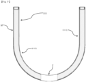
- a front ROPS left pillar member (80L) and a front ROPS right pillar member (80R) are obtained by dividing a U-shaped pipe member in the vicinity of a center of the U shape.
- the front ROPS left pillar member and the front ROPS right pillar member are obtained by dividing the U-shaped pipe member in the vicinity of the center of the U shape, and thus an inexpensive configuration can be implemented.
- the work vehicle further includes a rear ROPS member (90) attached to a rear wheel axle housing (41b) and the transmission mechanism (70).
- a first plate (91L, 91R) and a second plate (92L, 92R) are fixed to the rear ROPS member (90), the first plate (91L, 91R) is attached to the transmission mechanism (70), and the second plate (92L, 92R) is attached to the rear wheel axle housing (41b).
- the rear ROPS member is attached to the rear wheel axle housing and the transmission mechanism, the rear ROPS member can be more firmly attached.
- FIG. 1 is a left side view of the agricultural tractor according to the embodiment of the invention
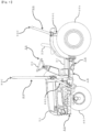
- FIG. 2 is a perspective view of the vicinity of a front ROPS member 80 and the vicinity of a rear ROPS member 90 of the agricultural tractor according to the embodiment of the invention
- FIG. 3A is a left side view of the vicinity of the front ROPS member 80 of the agricultural tractor according to the embodiment of the invention
- FIG. 3B is a left side view of the vicinity of the rear ROPS member 90 of the agricultural tractor according to the embodiment of the invention
- FIG. 4 is a front view illustrating a part of the front ROPS member 80 and a part of the rear ROPS member 90 of the agricultural tractor according to the embodiment of the invention.
- the agricultural tractor according to the present embodiment is an example of a work vehicle in the invention.
- An engine 30 is provided inside a bonnet 31 at a front portion of a vehicle body 10.
- Rotational power of the engine 30 is transmitted via various clutches inside a transmission case provided below a floor 21 of an operation unit 20. More specifically, the rotational power speed-changed by a main transmission and an auxiliary transmission is transmitted to a pair of left and right front wheels 40f and a pair of left and right rear wheels 40b.
- a steering wheel 23 is provided behind the engine 30 together with a dashboard cover, a meter panel, and a forward-reverse lever.
- a driver seat 22 is provided behind the steering wheel 23.
- a brake pedal disconnection pedal and a clutch pedal are disposed on a left side of the floor 21.
- a pair of left and right pedals including a brake pedal and an accelerator pedal are disposed on a right side of the floor 21.
- a work machine is mounted on a rear portion of the vehicle body 10 using, for example, a three-point link mechanism.
- a front frame 60 attached to the engine 30 which generates power using fuel is a frame that supports the front wheels 40f.
- the front frame 60 includes a front side frame attached to the engine 30, and the front side frame supports a front wheel axle housing functioning as a front wheel axle case that incorporates an axle of the front wheels 40f and supports a front-portion load of the vehicle body 10.
- the transmission mechanism 70 attached to the engine 30 is a mechanism that transmits the power generated by the engine 30 to the rear wheels 40b.
- the transmission mechanism 70 includes the transmission case attached to the engine 30.
- the transmission case incorporates a power transmission device that transmits the power of the engine 30 to driving wheels.
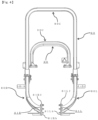
- FIG. 5 is a perspective view of the vicinity of the front ROPS member 80 of the agricultural tractor according to the embodiment of the invention
- FIG. 6 is a plan view of the vicinity of the front ROPS member 80 of the agricultural tractor according to the embodiment of the invention
- FIG. 7 is a front view illustrating a part of the front ROPS member 80 of the agricultural tractor according to the embodiment of the invention.
- the front ROPS member 80 is attached to the front frame 60 and a front portion 70f of the transmission mechanism 70.
- the front ROPS member 80 includes a front ROPS central arch member 80C which serves as an upper frame, and front ROPS left pillar member 80L and front ROPS right pillar member 80R which serve as lower frames
- the rear ROPS member 90 includes a rear ROPS central arch member 90C which serves as an upper frame and a rear ROPS left pillar member 90L and a rear ROPS right pillar member 90R which serve as lower frames.
- the front ROPS member 80 in front of the driver seat 22 is erected between the front wheels 40f and the rear wheels 40b as a safety frame capable of securing a survival space to protect a driver in the driver seat 22 even when the vehicle body 10 overturns.
- the rear ROPS member 90 whose ROPS base portion is attached to a rear wheel axle housing 41b functioning as a rear wheel axle case incorporating an axle of the rear wheels 40b for firmly supporting an entire load of the vehicle body 10 and which is erected behind the driver seat 22 is also effective as a safety frame, which is required to maintain a frame shape by preventing frame deformation even when the rear ROPS member 90 bears an entire weight of the vehicle body 10 due to overturning.
- the front ROPS member 80 which is attached not only to the front frame 60 but also to the front portion 70f of the transmission mechanism 70, has a firm vehicle body attachment and fixing configuration from the front frame 60 to the transmission mechanism 70, and thus, similarly to the rear ROPS member 90, a frame shape can be maintained by preventing frame deformation even when the front ROPS member 80 bears the entire weight of the vehicle body 10 due to the overturning.
- the front ROPS member 80 includes the front ROPS left pillar member 80L and the front ROPS right pillar member 80R that are erected on a left side and a right side in a vehicle body left-right direction, respectively.
- a front ROPS left plate 81L is fixed to a lower end of the front ROPS left pillar member 80L, a front portion 81Lf of the front ROPS left plate 81L is attached to the front frame 60, and a rear portion 81Lb of the front ROPS left plate 81L is attached to the front portion 70f of the transmission mechanism 70.
- fastening of three bolts in which a bolt shaft direction is the vehicle body left-right direction is used in attachment of the front portion 81Lf of the front ROPS left plate 81L
- fastening of four bolts in which a bolt shaft direction is the vehicle body left-right direction is used in attachment of the rear portion 81Lb of the front ROPS left plate 81L.
- the front frame 60 that functions as a front wheel axle bracket and the front portion 70f of the transmission mechanism 70 that functions as a clutch housing a configuration is adopted in which the front ROPS left plate 81L in the front ROPS left pillar member 80L of the front ROPS member 80 which is also referred to as a center ROPS, is attached at two positions, and thus strength is improved along with load distribution.
- a front ROPS right plate 81R is fixed to a lower end of the front ROPS right pillar member 80R, a front portion 81Rf of the front ROPS right plate 81R is attached to the front frame 60, and a rear portion 81Rb of the front ROPS right plate 81R is attached to the front portion 70f of the transmission mechanism 70.
- fastening of three bolts in which a bolt shaft direction is the vehicle body left-right direction is used in attachment of the front portion 81Rf of the front ROPS right plate 81R
- fastening of four bolts in which a bolt shaft direction is the vehicle body left-right direction is used in attachment of the rear portion 81Rb of the front ROPS right plate 81R.
- the front frame 60 that functions as the front wheel axle bracket and the front portion 70f of the transmission mechanism 70 that functions as the clutch housing a configuration is adopted in which the front ROPS right plate 81R in the front ROPS right pillar member 80R of the front ROPS member 80 which is also referred to as the center ROPS, is attached at two positions, and thus the strength is improved along with the load distribution.
- Left spacer plates 82L each having a thickness corresponding to a gap between the front portion 81Lf of the front ROPS left plate 81L and the front frame 60 are inserted.
- the front ROPS left plate 81L functioning as an attachment portion of the front ROPS member 80 which is also referred to as the center ROPS
- the front frame 60 functioning as the front wheel axle bracket
- the front ROPS left plate 81L, the left spacer plates 82L, and the front frame 60 by bolt fastening without directly affecting the engine 30, generation of a large load on the engine 30 is prevented.
- the front ROPS left plate 81L may be attached, by bolting, to the left spacer plates 82L fixed to the front frame 60 by welding or the like.
- Right spacer plates 82R each having a thickness corresponding to a gap between the front portion 81Rf of the front ROPS right plate 81R and the front frame 60 are inserted.
- the front ROPS right plate 81R functioning as an attachment portion of the front ROPS member 80 which is also referred to as the center ROPS
- the front frame 60 functioning as the front wheel axle bracket
- the front ROPS right plate 81R, the right spacer plates 82R, and the front frame 60 by bolt fastening without directly affecting the engine 30, generation of a large load on the engine 30 is prevented.
- the front ROPS right plate 81R may be attached, by bolting, to the right spacer plates 82R fixed to the front frame 60 by welding or the like.
- the front ROPS left pillar member 80L and the front ROPS right pillar member 80R are members obtained by dividing a U-shaped pipe member M in the vicinity of a center C of the U shape.
- the front ROPS left pillar member 80L and the front ROPS right pillar member 80R serving as the lower frames of the front ROPS member 80 are in a shape in which a U-shaped steel pipe bent at one position is divided into a left side and a right side. The bending of the lower frames is only performed once, and thus a processing cost and the like are reduced.
- FIG. 8 is a perspective view of the vicinity of the rear ROPS member 90 of the agricultural tractor according to the embodiment of the invention
- FIGS. 9 and 10 are left side views (part 1 and part 2) of the vicinity of the rear ROPS member 90 of the agricultural tractor according to the embodiment of the invention.
- the rear ROPS member 90 is attached to the rear wheel axle housing 41b and a rear portion 70b of the transmission mechanism 70.
- the rear ROPS member 90 includes the rear ROPS left pillar member 90L and the rear ROPS right pillar member 90R that are erected on the left side and the right side in the vehicle body left-right direction, respectively.
- a rear ROPS left L-shaped plate 91L and a rear ROPS left I-shaped plate 92L are fixed to a lower end of the rear ROPS left pillar member 90L, a left portion of the rear ROPS left L-shaped plate 91L and the rear ROPS left I-shaped plate 92L are attached to the rear wheel axle housing 41b, and a rear portion of the rear ROPS left L-shaped plate 91L is attached to the rear portion 70b of the transmission mechanism 70.
- fastening of two bolts in which a bolt shaft direction is the vehicle body left-right direction is used in attachment of the left portion of the rear ROPS left L-shaped plate 91L
- fastening of two bolts in which a bolt shaft direction is a vehicle body front-rear direction is used in attachment of the rear portion of the rear ROPS left L-shaped plate 91L
- fastening of three bolts in which a bolt shaft direction is the vehicle body left-right direction is used in attachment of the rear ROPS left I-shaped plate 92L.
- the rear ROPS left pillar member 90L functioning as the lower frame of the rear ROPS member 90 which is also referred to as a rear ROPS, is attached to the rear wheel axle housing 41b functioning as a rear axle housing at one position in the vicinity of a brake mechanism by using the rear ROPS left L-shaped plate 91L, and is not only attached to the rear portion 70b of the transmission mechanism 70 functioning as a rear transmission case at one position in the vicinity of an outer wall of the case, but also attached to the rear wheel axle housing 41b at one position in the vicinity of a wheel shaft through hole by using the rear ROPS left I-shaped plate 92L.
- a configuration is adopted in which the rear ROPS left L-shaped plate 91L and the rear ROPS left I-shaped plate 92L are attached at three positions in total, and thus the strength is improved along with the load distribution.
- a rear ROPS right L-shaped plate 91R and a rear ROPS right I-shaped plate 92R are fixed to a lower end of the rear ROPS right pillar member 90R, a right portion of the rear ROPS right L-shaped plate 91R and the rear ROPS right I-shaped plate 92R are attached to the rear wheel axle housing 41b, and a rear portion of the rear ROPS right L-shaped plate 91R is attached to the rear portion 70b of the transmission mechanism 70.
- fastening of two bolts in which a bolt shaft direction is the vehicle body left-right direction is used in attachment of the right portion of the rear ROPS right L-shaped plate 91R
- fastening of two bolts in which a bolt shaft direction is the vehicle body front-rear direction is used in attachment of the rear portion of the rear ROPS right L-shaped plate 91R
- fastening of three bolts in which a bolt shaft direction is the vehicle body left-right direction is used in attachment of the rear ROPS right I-shaped plate 92R.
- the rear ROPS right pillar member 90R functioning as the lower frame of the rear ROPS member 90 which is also referred to as the rear ROPS, is attached to the rear wheel axle housing 41b functioning as the rear axle housing at one position in the vicinity of the brake mechanism by using the rear ROPS right L-shaped plate 91R, and is not only attached to the rear portion 70b of the transmission mechanism 70 functioning as the rear transmission case at one position in the vicinity of the outer wall of the case, but also attached to the rear wheel axle housing 41b at one position in the vicinity of the wheel shaft through hole by using the rear ROPS right I-shaped plate 92R.
- a configuration is adopted in which the rear ROPS right L-shaped plate 91R and the rear ROPS right I-shaped plate 92R are attached at three positions in total, and thus the strength is improved along with the load distribution.
- the work vehicle in the invention can implement a firmer attachment of the front ROPS member and is useful as a work vehicle such as an agricultural tractor.
- a work vehicle such as an agricultural tractor having a front ROPS member is known.
- a work vehicle includes a front frame (60) configured to support a front wheel (40f), a transmission mechanism (70) configured to transmit power, and a front ROPS member (80).
- the front ROPS member (80) is fixed to a front ROPS left plate (81L) and a front ROPS right plate (81R), and each of the front ROPS left plate (81L) and the front ROPS right plate (81R) is attached to the front frame (60) and the transmission mechanism (70).
Landscapes
- Engineering & Computer Science (AREA)
- Mechanical Engineering (AREA)
- Body Structure For Vehicles (AREA)
Abstract
Description
- The present invention relates to a work vehicle such as an agricultural tractor.
- A work vehicle such as an agricultural tractor having a front ROPS member is known (see, for example, PTL 1).
- PTL 1:
JP6611669B - However, in the work vehicle such as the agricultural tractor in the related art as described above, attachment of the ROPS member is not always sufficiently firm.
- An object of the invention is to provide a work vehicle on which a ROPS member can be more firmly attached in consideration of the above-described problem in the related art.
- According to a first aspect of the invention, a work vehicle includes: a front frame (60) configured to support a front wheel (40f); a transmission mechanism (70) configured to transmit power; and a front ROPS member (80), the front ROPS member (80) is fixed to a front ROPS left plate (81L) and a front ROPS right plate (81R), and each of the front ROPS left plate (81L) and the front ROPS right plate (81R) is attached to the front frame (60) and the transmission mechanism (70).
- Accordingly, a simple attachment configuration of the ROPS member can be implemented.
- In a second aspect of the invention according to the work vehicle of the first aspect of the invention, a left spacer plate (82L) is inserted between a front portion of the front ROPS left plate (81L) and the front frame (60), and a right spacer plate (82R) is inserted between a front portion of the front ROPS right plate (81R) and the front frame (60).
- Accordingly, since the left spacer plate is inserted and the right spacer plate is inserted, a flexible configuration can be implemented.
- In a third aspect of the invention, in the front ROPS member (80), a front ROPS left pillar member (80L) and a front ROPS right pillar member (80R) are obtained by dividing a U-shaped pipe member in the vicinity of a center of the U shape.
- Therefore, the front ROPS left pillar member and the front ROPS right pillar member are obtained by dividing the U-shaped pipe member in the vicinity of the center of the U shape, and thus an inexpensive configuration can be implemented.
- In a fourth aspect of the invention according to the work vehicle according to any one of the first to third aspects of the invention, the work vehicle further includes a rear ROPS member (90) attached to a rear wheel axle housing (41b) and the transmission mechanism (70).
- In a fifth aspect of the invention according to the work vehicle according to the fourth aspect of the invention, a first plate (91L, 91R) and a second plate (92L, 92R) are fixed to the rear ROPS member (90), the first plate (91L, 91R) is attached to the transmission mechanism (70), and the second plate (92L, 92R) is attached to the rear wheel axle housing (41b).
- Accordingly, since the rear ROPS member is attached to the rear wheel axle housing and the transmission mechanism, the rear ROPS member can be more firmly attached.
- According to the invention, it is possible to provide a work vehicle on which a ROPS member can be more firmly attached.
-
-
FIG. 1 is a left side view of an agricultural tractor according to an embodiment of the invention; -
FIG. 2 is a perspective view of the vicinity of a front ROPS member and the vicinity of a rear ROPS member of the agricultural tractor according to the embodiment of the invention; -
FIG. 3A is a left side view of the vicinity of the front ROPS member of the agricultural tractor according to the embodiment of the invention, andFIG. 3B is a left side view of the vicinity of the rear ROPS member of the agricultural tractor according to the embodiment of the invention; -
FIG. 4 is a front view illustrating a part of the front ROPS member and a part of the rear ROPS member of the agricultural tractor according to the embodiment of the invention; -
FIG. 5 is a perspective view of the vicinity of the front ROPS member of the agricultural tractor according to the embodiment of the invention; -
FIG. 6 is a plan view of the vicinity of the front ROPS member of the agricultural tractor according to the embodiment of the invention; -
FIG. 7 is a front view illustrating a part of the front ROPS member of the agricultural tractor according to the embodiment of the invention; -
FIG. 8 is a perspective view of the vicinity of the rear ROPS member of the agricultural tractor according to the embodiment of the invention; -
FIG. 9 is a left side view (part 1) of the vicinity of the rear ROPS member of the agricultural tractor according to the embodiment of the invention; and -
FIG. 10 is a left side view (part 2) of the vicinity of the rear ROPS member of the agricultural tractor according to the embodiment of the invention. - An embodiment of the invention will be described in detail with reference to the drawings.
- Some components may not be illustrated in the drawings or may be transparently illustrated or omitted, and the same applies hereinafter.
- (1) First, a configuration and an operation of an agricultural tractor according to the embodiment of the invention will be described specifically with reference to
FIGS. 1 to 4 . - Here,
FIG. 1 is a left side view of the agricultural tractor according to the embodiment of the invention,FIG. 2 is a perspective view of the vicinity of afront ROPS member 80 and the vicinity of arear ROPS member 90 of the agricultural tractor according to the embodiment of the invention,FIG. 3A is a left side view of the vicinity of thefront ROPS member 80 of the agricultural tractor according to the embodiment of the invention,FIG. 3B is a left side view of the vicinity of therear ROPS member 90 of the agricultural tractor according to the embodiment of the invention, andFIG. 4 is a front view illustrating a part of thefront ROPS member 80 and a part of therear ROPS member 90 of the agricultural tractor according to the embodiment of the invention. - The agricultural tractor according to the present embodiment is an example of a work vehicle in the invention.
- An
engine 30 is provided inside abonnet 31 at a front portion of avehicle body 10. - Rotational power of the
engine 30 is transmitted via various clutches inside a transmission case provided below afloor 21 of anoperation unit 20. More specifically, the rotational power speed-changed by a main transmission and an auxiliary transmission is transmitted to a pair of left and right front wheels 40f and a pair of left and right rear wheels 40b. - A
steering wheel 23 is provided behind theengine 30 together with a dashboard cover, a meter panel, and a forward-reverse lever. - A
driver seat 22 is provided behind thesteering wheel 23. - A brake pedal disconnection pedal and a clutch pedal are disposed on a left side of the
floor 21. A pair of left and right pedals including a brake pedal and an accelerator pedal are disposed on a right side of thefloor 21. - A work machine is mounted on a rear portion of the
vehicle body 10 using, for example, a three-point link mechanism. - A
front frame 60 attached to theengine 30 which generates power using fuel is a frame that supports the front wheels 40f. - For example, the
front frame 60 includes a front side frame attached to theengine 30, and the front side frame supports a front wheel axle housing functioning as a front wheel axle case that incorporates an axle of the front wheels 40f and supports a front-portion load of thevehicle body 10. - The
transmission mechanism 70 attached to theengine 30 is a mechanism that transmits the power generated by theengine 30 to the rear wheels 40b. - For example, the
transmission mechanism 70 includes the transmission case attached to theengine 30. The transmission case incorporates a power transmission device that transmits the power of theengine 30 to driving wheels. - (2) Next, the configuration and the operation of the agricultural tractor according to the embodiment of the invention will be described more specifically mainly with reference to
FIGS. 2 to 7 . - Here,
FIG. 5 is a perspective view of the vicinity of thefront ROPS member 80 of the agricultural tractor according to the embodiment of the invention,FIG. 6 is a plan view of the vicinity of thefront ROPS member 80 of the agricultural tractor according to the embodiment of the invention, andFIG. 7 is a front view illustrating a part of thefront ROPS member 80 of the agricultural tractor according to the embodiment of the invention. - The
front ROPS member 80 is attached to thefront frame 60 and a front portion 70f of thetransmission mechanism 70. - For example, the
front ROPS member 80 includes a front ROPScentral arch member 80C which serves as an upper frame, and front ROPSleft pillar member 80L and front ROPSright pillar member 80R which serve as lower frames, and therear ROPS member 90 includes a rear ROPScentral arch member 90C which serves as an upper frame and a rear ROPSleft pillar member 90L and a rear ROPSright pillar member 90R which serve as lower frames. - The
front ROPS member 80 in front of thedriver seat 22 is erected between the front wheels 40f and the rear wheels 40b as a safety frame capable of securing a survival space to protect a driver in thedriver seat 22 even when thevehicle body 10 overturns. - Of course, the
rear ROPS member 90 whose ROPS base portion is attached to a rear wheel axle housing 41b functioning as a rear wheel axle case incorporating an axle of the rear wheels 40b for firmly supporting an entire load of thevehicle body 10 and which is erected behind thedriver seat 22 is also effective as a safety frame, which is required to maintain a frame shape by preventing frame deformation even when therear ROPS member 90 bears an entire weight of thevehicle body 10 due to overturning. However, when the agricultural tractor travels in a narrow space such as an orchard and a cultivation greenhouse, it is often desirable for the driver to perform a traveling operation while monitoring that the safety frame does not come into contact with trees in the orchard and a ceiling of the cultivation greenhouse, and thus a demand for thefront ROPS member 80 erected in front of thedriver seat 22 is not low. - The
front ROPS member 80, which is attached not only to thefront frame 60 but also to the front portion 70f of thetransmission mechanism 70, has a firm vehicle body attachment and fixing configuration from thefront frame 60 to thetransmission mechanism 70, and thus, similarly to therear ROPS member 90, a frame shape can be maintained by preventing frame deformation even when thefront ROPS member 80 bears the entire weight of thevehicle body 10 due to the overturning. - The
front ROPS member 80 includes the front ROPSleft pillar member 80L and the front ROPSright pillar member 80R that are erected on a left side and a right side in a vehicle body left-right direction, respectively. - A front ROPS left plate 81L is fixed to a lower end of the front ROPS
left pillar member 80L, a front portion 81Lf of the front ROPS left plate 81L is attached to thefront frame 60, and a rear portion 81Lb of the front ROPS left plate 81L is attached to the front portion 70f of thetransmission mechanism 70. - More specifically, fastening of three bolts in which a bolt shaft direction is the vehicle body left-right direction is used in attachment of the front portion 81Lf of the front ROPS left plate 81L, and fastening of four bolts in which a bolt shaft direction is the vehicle body left-right direction is used in attachment of the rear portion 81Lb of the front ROPS left plate 81L.
- By using the
front frame 60 that functions as a front wheel axle bracket and the front portion 70f of thetransmission mechanism 70 that functions as a clutch housing, a configuration is adopted in which the front ROPS left plate 81L in the front ROPS leftpillar member 80L of thefront ROPS member 80 which is also referred to as a center ROPS, is attached at two positions, and thus strength is improved along with load distribution. - A front ROPS
right plate 81R is fixed to a lower end of the front ROPSright pillar member 80R, a front portion 81Rf of the front ROPSright plate 81R is attached to thefront frame 60, and a rear portion 81Rb of the front ROPSright plate 81R is attached to the front portion 70f of thetransmission mechanism 70. - More specifically, fastening of three bolts in which a bolt shaft direction is the vehicle body left-right direction is used in attachment of the front portion 81Rf of the front ROPS
right plate 81R, and fastening of four bolts in which a bolt shaft direction is the vehicle body left-right direction is used in attachment of the rear portion 81Rb of the front ROPSright plate 81R. - By using the
front frame 60 that functions as the front wheel axle bracket and the front portion 70f of thetransmission mechanism 70 that functions as the clutch housing, a configuration is adopted in which the front ROPSright plate 81R in the front ROPSright pillar member 80R of thefront ROPS member 80 which is also referred to as the center ROPS, is attached at two positions, and thus the strength is improved along with the load distribution. - Left spacer plates 82L each having a thickness corresponding to a gap between the front portion 81Lf of the front ROPS left plate 81L and the
front frame 60 are inserted. - By simply changing thicknesses of the two left spacer plates 82L between the front ROPS left plate 81L functioning as an attachment portion of the
front ROPS member 80 which is also referred to as the center ROPS, and thefront frame 60 functioning as the front wheel axle bracket, a flexible measure against a width of the front wheel axle bracket in the vehicle body left-right direction, which varies depending on a tractor model, is implemented, and thus sharing of the center ROPS is promoted. By attaching the front ROPS left plate 81L, the left spacer plates 82L, and thefront frame 60 by bolt fastening without directly affecting theengine 30, generation of a large load on theengine 30 is prevented. Of course, the front ROPS left plate 81L may be attached, by bolting, to the left spacer plates 82L fixed to thefront frame 60 by welding or the like. - Right spacer plates 82R each having a thickness corresponding to a gap between the front portion 81Rf of the front ROPS
right plate 81R and thefront frame 60 are inserted. - By simply changing thicknesses of the two right spacer plates 82R between the front ROPS
right plate 81R functioning as an attachment portion of thefront ROPS member 80 which is also referred to as the center ROPS, and thefront frame 60 functioning as the front wheel axle bracket, a flexible measure against the width of the front wheel axle bracket in the vehicle body left-right direction, which varies depending on the tractor model, is implemented, and thus sharing of the center ROPS is promoted. By attaching the front ROPSright plate 81R, the right spacer plates 82R, and thefront frame 60 by bolt fastening without directly affecting theengine 30, generation of a large load on theengine 30 is prevented. Of course, the front ROPSright plate 81R may be attached, by bolting, to the right spacer plates 82R fixed to thefront frame 60 by welding or the like. - The front ROPS left
pillar member 80L and the front ROPSright pillar member 80R are members obtained by dividing a U-shaped pipe member M in the vicinity of a center C of the U shape. - More specifically, the front ROPS left
pillar member 80L and the front ROPSright pillar member 80R serving as the lower frames of thefront ROPS member 80 are in a shape in which a U-shaped steel pipe bent at one position is divided into a left side and a right side. The bending of the lower frames is only performed once, and thus a processing cost and the like are reduced. - In this manner, since the front ROPS left
pillar member 80L and the front ROPSright pillar member 80R that function as the lower frames of the center ROPS are collectively implemented by using the steel pipe with a large bending degree, an unnecessary portion of the pipe member M in the vicinity of the center C, which is a portion removed along with the division, is reduced. - (3) Next, the configuration and the operation of the agricultural tractor according to the embodiment of the invention will be described further more specifically mainly with reference to
FIGS. 8 to 10 . -
FIG. 8 is a perspective view of the vicinity of therear ROPS member 90 of the agricultural tractor according to the embodiment of the invention, andFIGS. 9 and10 are left side views (part 1 and part 2) of the vicinity of therear ROPS member 90 of the agricultural tractor according to the embodiment of the invention. - The
rear ROPS member 90 is attached to the rear wheel axle housing 41b and a rear portion 70b of thetransmission mechanism 70. - The
rear ROPS member 90 includes the rear ROPS leftpillar member 90L and the rear ROPSright pillar member 90R that are erected on the left side and the right side in the vehicle body left-right direction, respectively. - A rear ROPS left L-shaped plate 91L and a rear ROPS left I-shaped plate 92L are fixed to a lower end of the rear ROPS left
pillar member 90L, a left portion of the rear ROPS left L-shaped plate 91L and the rear ROPS left I-shaped plate 92L are attached to the rear wheel axle housing 41b, and a rear portion of the rear ROPS left L-shaped plate 91L is attached to the rear portion 70b of thetransmission mechanism 70. - More specifically, fastening of two bolts in which a bolt shaft direction is the vehicle body left-right direction is used in attachment of the left portion of the rear ROPS left L-shaped plate 91L, fastening of two bolts in which a bolt shaft direction is a vehicle body front-rear direction is used in attachment of the rear portion of the rear ROPS left L-shaped plate 91L, and fastening of three bolts in which a bolt shaft direction is the vehicle body left-right direction is used in attachment of the rear ROPS left I-shaped plate 92L.
- The rear ROPS left
pillar member 90L functioning as the lower frame of therear ROPS member 90 which is also referred to as a rear ROPS, is attached to the rear wheel axle housing 41b functioning as a rear axle housing at one position in the vicinity of a brake mechanism by using the rear ROPS left L-shaped plate 91L, and is not only attached to the rear portion 70b of thetransmission mechanism 70 functioning as a rear transmission case at one position in the vicinity of an outer wall of the case, but also attached to the rear wheel axle housing 41b at one position in the vicinity of a wheel shaft through hole by using the rear ROPS left I-shaped plate 92L. In this manner, a configuration is adopted in which the rear ROPS left L-shaped plate 91L and the rear ROPS left I-shaped plate 92L are attached at three positions in total, and thus the strength is improved along with the load distribution. - A rear ROPS right L-shaped
plate 91R and a rear ROPS right I-shaped plate 92R are fixed to a lower end of the rear ROPSright pillar member 90R, a right portion of the rear ROPS right L-shapedplate 91R and the rear ROPS right I-shaped plate 92R are attached to the rear wheel axle housing 41b, and a rear portion of the rear ROPS right L-shapedplate 91R is attached to the rear portion 70b of thetransmission mechanism 70. - More specifically, fastening of two bolts in which a bolt shaft direction is the vehicle body left-right direction is used in attachment of the right portion of the rear ROPS right L-shaped
plate 91R, fastening of two bolts in which a bolt shaft direction is the vehicle body front-rear direction is used in attachment of the rear portion of the rear ROPS right L-shapedplate 91R, and fastening of three bolts in which a bolt shaft direction is the vehicle body left-right direction is used in attachment of the rear ROPS right I-shaped plate 92R. - The rear ROPS
right pillar member 90R functioning as the lower frame of therear ROPS member 90 which is also referred to as the rear ROPS, is attached to the rear wheel axle housing 41b functioning as the rear axle housing at one position in the vicinity of the brake mechanism by using the rear ROPS right L-shapedplate 91R, and is not only attached to the rear portion 70b of thetransmission mechanism 70 functioning as the rear transmission case at one position in the vicinity of the outer wall of the case, but also attached to the rear wheel axle housing 41b at one position in the vicinity of the wheel shaft through hole by using the rear ROPS right I-shaped plate 92R. In this manner, a configuration is adopted in which the rear ROPS right L-shapedplate 91R and the rear ROPS right I-shaped plate 92R are attached at three positions in total, and thus the strength is improved along with the load distribution. - The work vehicle in the invention can implement a firmer attachment of the front ROPS member and is useful as a work vehicle such as an agricultural tractor.
- A work vehicle such as an agricultural tractor having a front ROPS member is known. However, in the work vehicle such as the agricultural tractor in the related art, attachment of the ROPS member is not always sufficiently firm. A work vehicle includes a front frame (60) configured to support a front wheel (40f), a transmission mechanism (70) configured to transmit power, and a front ROPS member (80). The front ROPS member (80) is fixed to a front ROPS left plate (81L) and a front ROPS right plate (81R), and each of the front ROPS left plate (81L) and the front ROPS right plate (81R) is attached to the front frame (60) and the transmission mechanism (70).
Claims (5)
- A work vehicle comprising:a front frame (60) configured to support a front wheel (40f);a transmission mechanism (70) configured to transmit power; anda front ROPS member (80), whereinthe front ROPS member (80) is fixed to a front ROPS left plate (81L) and a front ROPS right plate (81R), andeach of the front ROPS left plate (81L) and the front ROPS right plate (81R) is attached to the front frame (60) and the transmission mechanism (70).
- The work vehicle according to claim 1, whereina left spacer plate (82L) is inserted between the front ROPS left plate (81L) and the front frame (60), anda right spacer plate (82R) is inserted between the front ROPS right plate (81R) and the front frame (60).
- The work vehicle according to claim 1 or 2, wherein
in the front ROPS member (80), a front ROPS left pillar member (80L) and a front ROPS right pillar member (80R) are obtained by dividing a U-shaped pipe member in the vicinity of a center of the U shape. - The work vehicle according to any one of claims 1 to 3, further comprising:
a rear ROPS member (90) attached to a rear wheel axle housing (41b) and the transmission mechanism (70). - The work vehicle according to claim 4, wherein
a first plate (91L, 91R) and a second plate (92L, 92R) are fixed to the rear ROPS member (90), the first plate (91L, 91R) is attached to the transmission mechanism (70), and the second plate (92L, 92R) is attached to the rear wheel axle housing (41b).
Applications Claiming Priority (1)
| Application Number | Priority Date | Filing Date | Title |
|---|---|---|---|
| JP2021199443A JP7753849B2 (en) | 2021-12-08 | 2021-12-08 | Work vehicles |
Publications (2)
| Publication Number | Publication Date |
|---|---|
| EP4194281A1 true EP4194281A1 (en) | 2023-06-14 |
| EP4194281B1 EP4194281B1 (en) | 2025-03-19 |
Family
ID=84439976
Family Applications (1)
| Application Number | Title | Priority Date | Filing Date |
|---|---|---|---|
| EP22211878.8A Active EP4194281B1 (en) | 2021-12-08 | 2022-12-07 | Work vehicle |
Country Status (2)
| Country | Link |
|---|---|
| EP (1) | EP4194281B1 (en) |
| JP (2) | JP7753849B2 (en) |
Citations (6)
| Publication number | Priority date | Publication date | Assignee | Title |
|---|---|---|---|---|
| GB996000A (en) * | 1960-08-26 | 1965-06-23 | Massey Ferguson Perkins Ltd | Improvements in or relating to means for coupling implements to tractors |
| FR1564979A (en) * | 1967-03-28 | 1969-04-25 | ||
| JPS58209664A (en) * | 1982-05-30 | 1983-12-06 | Iseki & Co Ltd | Structure of safety frame attachment part |
| US20110233909A1 (en) * | 2010-03-24 | 2011-09-29 | Kubota Corporation | Tractor |
| EP3470583A2 (en) * | 2017-10-10 | 2019-04-17 | Kubota Corporation | Tractor |
| US20200398780A1 (en) * | 2017-12-18 | 2020-12-24 | Kubota Corporation | Tractor and Working Vehicle |
Family Cites Families (4)
| Publication number | Priority date | Publication date | Assignee | Title |
|---|---|---|---|---|
| JPS6026976U (en) * | 1984-06-08 | 1985-02-23 | 井関農機株式会社 | Tractor implement mounting device |
| JPH045428Y2 (en) * | 1984-12-17 | 1992-02-17 | ||
| KR101551478B1 (en) * | 2013-09-24 | 2015-09-09 | 대동공업주식회사 | Front loader and front loader with a Agricultural |
| JP2021181265A (en) | 2020-05-19 | 2021-11-25 | 井関農機株式会社 | Work vehicle |
-
2021
- 2021-12-08 JP JP2021199443A patent/JP7753849B2/en active Active
-
2022
- 2022-12-07 EP EP22211878.8A patent/EP4194281B1/en active Active
-
2025
- 2025-08-01 JP JP2025129644A patent/JP2025147017A/en active Pending
Patent Citations (6)
| Publication number | Priority date | Publication date | Assignee | Title |
|---|---|---|---|---|
| GB996000A (en) * | 1960-08-26 | 1965-06-23 | Massey Ferguson Perkins Ltd | Improvements in or relating to means for coupling implements to tractors |
| FR1564979A (en) * | 1967-03-28 | 1969-04-25 | ||
| JPS58209664A (en) * | 1982-05-30 | 1983-12-06 | Iseki & Co Ltd | Structure of safety frame attachment part |
| US20110233909A1 (en) * | 2010-03-24 | 2011-09-29 | Kubota Corporation | Tractor |
| EP3470583A2 (en) * | 2017-10-10 | 2019-04-17 | Kubota Corporation | Tractor |
| US20200398780A1 (en) * | 2017-12-18 | 2020-12-24 | Kubota Corporation | Tractor and Working Vehicle |
Also Published As
| Publication number | Publication date |
|---|---|
| EP4194281B1 (en) | 2025-03-19 |
| JP7753849B2 (en) | 2025-10-15 |
| JP2025147017A (en) | 2025-10-03 |
| JP2023085003A (en) | 2023-06-20 |
Similar Documents
| Publication | Publication Date | Title |
|---|---|---|
| KR20230062395A (en) | Electric tractor | |
| US9994158B2 (en) | Working vehicle | |
| EP4194281A1 (en) | Work vehicle | |
| KR102235780B1 (en) | Agricultural vehicle | |
| US20150151635A1 (en) | Vehicle | |
| JP7396232B2 (en) | work vehicle | |
| JP5921206B2 (en) | Step unit for work vehicle | |
| US20160039283A1 (en) | Tractor | |
| JP7032297B2 (en) | Work platform | |
| JP2013147151A (en) | Working vehicle | |
| JP6915589B2 (en) | Work vehicle | |
| JP2017178270A (en) | Saddle riding | |
| JP3056716B2 (en) | Construction Machine Main Frame | |
| JP7396234B2 (en) | work vehicle | |
| EP4530501A1 (en) | Work vehicle | |
| JP2010058616A (en) | Underguard | |
| JP6866886B2 (en) | How to assemble the work vehicle and fuel tank to the airframe | |
| JP6482430B2 (en) | Work vehicle | |
| US11370289B2 (en) | Work vehicle | |
| JP4904636B2 (en) | Tractor frame | |
| JP6915588B2 (en) | Work vehicle | |
| KR20200105377A (en) | Agricultural Vehicle | |
| JP3372441B2 (en) | Paddy field machine frame structure | |
| US20210197663A1 (en) | Work vehicle | |
| JPS5934514Y2 (en) | Vehicle hydraulic control lever device |
Legal Events
| Date | Code | Title | Description |
|---|---|---|---|
| PUAI | Public reference made under article 153(3) epc to a published international application that has entered the european phase |
Free format text: ORIGINAL CODE: 0009012 |
|
| STAA | Information on the status of an ep patent application or granted ep patent |
Free format text: STATUS: THE APPLICATION HAS BEEN PUBLISHED |
|
| AK | Designated contracting states |
Kind code of ref document: A1 Designated state(s): AL AT BE BG CH CY CZ DE DK EE ES FI FR GB GR HR HU IE IS IT LI LT LU LV MC ME MK MT NL NO PL PT RO RS SE SI SK SM TR |
|
| STAA | Information on the status of an ep patent application or granted ep patent |
Free format text: STATUS: REQUEST FOR EXAMINATION WAS MADE |
|
| 17P | Request for examination filed |
Effective date: 20230816 |
|
| RBV | Designated contracting states (corrected) |
Designated state(s): AL AT BE BG CH CY CZ DE DK EE ES FI FR GB GR HR HU IE IS IT LI LT LU LV MC ME MK MT NL NO PL PT RO RS SE SI SK SM TR |
|
| GRAP | Despatch of communication of intention to grant a patent |
Free format text: ORIGINAL CODE: EPIDOSNIGR1 |
|
| STAA | Information on the status of an ep patent application or granted ep patent |
Free format text: STATUS: GRANT OF PATENT IS INTENDED |
|
| INTG | Intention to grant announced |
Effective date: 20241008 |
|
| GRAS | Grant fee paid |
Free format text: ORIGINAL CODE: EPIDOSNIGR3 |
|
| GRAA | (expected) grant |
Free format text: ORIGINAL CODE: 0009210 |
|
| STAA | Information on the status of an ep patent application or granted ep patent |
Free format text: STATUS: THE PATENT HAS BEEN GRANTED |
|
| AK | Designated contracting states |
Kind code of ref document: B1 Designated state(s): AL AT BE BG CH CY CZ DE DK EE ES FI FR GB GR HR HU IE IS IT LI LT LU LV MC ME MK MT NL NO PL PT RO RS SE SI SK SM TR |
|
| REG | Reference to a national code |
Ref country code: GB Ref legal event code: FG4D |
|
| REG | Reference to a national code |
Ref country code: CH Ref legal event code: EP |
|
| REG | Reference to a national code |
Ref country code: DE Ref legal event code: R096 Ref document number: 602022011941 Country of ref document: DE |
|
| REG | Reference to a national code |
Ref country code: IE Ref legal event code: FG4D |
|
| PG25 | Lapsed in a contracting state [announced via postgrant information from national office to epo] |
Ref country code: RS Free format text: LAPSE BECAUSE OF FAILURE TO SUBMIT A TRANSLATION OF THE DESCRIPTION OR TO PAY THE FEE WITHIN THE PRESCRIBED TIME-LIMIT Effective date: 20250619 |
|
| PG25 | Lapsed in a contracting state [announced via postgrant information from national office to epo] |
Ref country code: FI Free format text: LAPSE BECAUSE OF FAILURE TO SUBMIT A TRANSLATION OF THE DESCRIPTION OR TO PAY THE FEE WITHIN THE PRESCRIBED TIME-LIMIT Effective date: 20250319 |
|
| REG | Reference to a national code |
Ref country code: LT Ref legal event code: MG9D |
|
| PG25 | Lapsed in a contracting state [announced via postgrant information from national office to epo] |
Ref country code: NO Free format text: LAPSE BECAUSE OF FAILURE TO SUBMIT A TRANSLATION OF THE DESCRIPTION OR TO PAY THE FEE WITHIN THE PRESCRIBED TIME-LIMIT Effective date: 20250619 |
|
| PG25 | Lapsed in a contracting state [announced via postgrant information from national office to epo] |
Ref country code: HR Free format text: LAPSE BECAUSE OF FAILURE TO SUBMIT A TRANSLATION OF THE DESCRIPTION OR TO PAY THE FEE WITHIN THE PRESCRIBED TIME-LIMIT Effective date: 20250319 |
|
| PG25 | Lapsed in a contracting state [announced via postgrant information from national office to epo] |
Ref country code: LV Free format text: LAPSE BECAUSE OF FAILURE TO SUBMIT A TRANSLATION OF THE DESCRIPTION OR TO PAY THE FEE WITHIN THE PRESCRIBED TIME-LIMIT Effective date: 20250319 |
|
| PG25 | Lapsed in a contracting state [announced via postgrant information from national office to epo] |
Ref country code: BG Free format text: LAPSE BECAUSE OF FAILURE TO SUBMIT A TRANSLATION OF THE DESCRIPTION OR TO PAY THE FEE WITHIN THE PRESCRIBED TIME-LIMIT Effective date: 20250319 Ref country code: GR Free format text: LAPSE BECAUSE OF FAILURE TO SUBMIT A TRANSLATION OF THE DESCRIPTION OR TO PAY THE FEE WITHIN THE PRESCRIBED TIME-LIMIT Effective date: 20250620 |
|
| REG | Reference to a national code |
Ref country code: NL Ref legal event code: MP Effective date: 20250319 |
|
| REG | Reference to a national code |
Ref country code: AT Ref legal event code: MK05 Ref document number: 1776726 Country of ref document: AT Kind code of ref document: T Effective date: 20250319 |
|
| PG25 | Lapsed in a contracting state [announced via postgrant information from national office to epo] |
Ref country code: NL Free format text: LAPSE BECAUSE OF FAILURE TO SUBMIT A TRANSLATION OF THE DESCRIPTION OR TO PAY THE FEE WITHIN THE PRESCRIBED TIME-LIMIT Effective date: 20250319 |
|
| PG25 | Lapsed in a contracting state [announced via postgrant information from national office to epo] |
Ref country code: SE Free format text: LAPSE BECAUSE OF FAILURE TO SUBMIT A TRANSLATION OF THE DESCRIPTION OR TO PAY THE FEE WITHIN THE PRESCRIBED TIME-LIMIT Effective date: 20250319 |
|
| PG25 | Lapsed in a contracting state [announced via postgrant information from national office to epo] |
Ref country code: SM Free format text: LAPSE BECAUSE OF FAILURE TO SUBMIT A TRANSLATION OF THE DESCRIPTION OR TO PAY THE FEE WITHIN THE PRESCRIBED TIME-LIMIT Effective date: 20250319 |
|
| PG25 | Lapsed in a contracting state [announced via postgrant information from national office to epo] |
Ref country code: ES Free format text: LAPSE BECAUSE OF FAILURE TO SUBMIT A TRANSLATION OF THE DESCRIPTION OR TO PAY THE FEE WITHIN THE PRESCRIBED TIME-LIMIT Effective date: 20250319 Ref country code: PT Free format text: LAPSE BECAUSE OF FAILURE TO SUBMIT A TRANSLATION OF THE DESCRIPTION OR TO PAY THE FEE WITHIN THE PRESCRIBED TIME-LIMIT Effective date: 20250721 |
|
| PG25 | Lapsed in a contracting state [announced via postgrant information from national office to epo] |
Ref country code: PL Free format text: LAPSE BECAUSE OF FAILURE TO SUBMIT A TRANSLATION OF THE DESCRIPTION OR TO PAY THE FEE WITHIN THE PRESCRIBED TIME-LIMIT Effective date: 20250319 Ref country code: IT Free format text: LAPSE BECAUSE OF FAILURE TO SUBMIT A TRANSLATION OF THE DESCRIPTION OR TO PAY THE FEE WITHIN THE PRESCRIBED TIME-LIMIT Effective date: 20250319 |
|
| PG25 | Lapsed in a contracting state [announced via postgrant information from national office to epo] |
Ref country code: AT Free format text: LAPSE BECAUSE OF FAILURE TO SUBMIT A TRANSLATION OF THE DESCRIPTION OR TO PAY THE FEE WITHIN THE PRESCRIBED TIME-LIMIT Effective date: 20250319 |
|
| PG25 | Lapsed in a contracting state [announced via postgrant information from national office to epo] |
Ref country code: CZ Free format text: LAPSE BECAUSE OF FAILURE TO SUBMIT A TRANSLATION OF THE DESCRIPTION OR TO PAY THE FEE WITHIN THE PRESCRIBED TIME-LIMIT Effective date: 20250319 Ref country code: EE Free format text: LAPSE BECAUSE OF FAILURE TO SUBMIT A TRANSLATION OF THE DESCRIPTION OR TO PAY THE FEE WITHIN THE PRESCRIBED TIME-LIMIT Effective date: 20250319 |
|
| PG25 | Lapsed in a contracting state [announced via postgrant information from national office to epo] |
Ref country code: RO Free format text: LAPSE BECAUSE OF FAILURE TO SUBMIT A TRANSLATION OF THE DESCRIPTION OR TO PAY THE FEE WITHIN THE PRESCRIBED TIME-LIMIT Effective date: 20250319 |
|
| PG25 | Lapsed in a contracting state [announced via postgrant information from national office to epo] |
Ref country code: SK Free format text: LAPSE BECAUSE OF FAILURE TO SUBMIT A TRANSLATION OF THE DESCRIPTION OR TO PAY THE FEE WITHIN THE PRESCRIBED TIME-LIMIT Effective date: 20250319 |
|
| PG25 | Lapsed in a contracting state [announced via postgrant information from national office to epo] |
Ref country code: IS Free format text: LAPSE BECAUSE OF FAILURE TO SUBMIT A TRANSLATION OF THE DESCRIPTION OR TO PAY THE FEE WITHIN THE PRESCRIBED TIME-LIMIT Effective date: 20250719 |
|
| REG | Reference to a national code |
Ref country code: DE Ref legal event code: R097 Ref document number: 602022011941 Country of ref document: DE |
|
| PG25 | Lapsed in a contracting state [announced via postgrant information from national office to epo] |
Ref country code: DK Free format text: LAPSE BECAUSE OF FAILURE TO SUBMIT A TRANSLATION OF THE DESCRIPTION OR TO PAY THE FEE WITHIN THE PRESCRIBED TIME-LIMIT Effective date: 20250319 |
|
| PGFP | Annual fee paid to national office [announced via postgrant information from national office to epo] |
Ref country code: FR Payment date: 20251217 Year of fee payment: 4 |
|
| PLBE | No opposition filed within time limit |
Free format text: ORIGINAL CODE: 0009261 |
|
| STAA | Information on the status of an ep patent application or granted ep patent |
Free format text: STATUS: NO OPPOSITION FILED WITHIN TIME LIMIT |
|
| REG | Reference to a national code |
Ref country code: CH Ref legal event code: L10 Free format text: ST27 STATUS EVENT CODE: U-0-0-L10-L00 (AS PROVIDED BY THE NATIONAL OFFICE) Effective date: 20260128 |
|
| 26N | No opposition filed |
Effective date: 20251222 |
|
| PGFP | Annual fee paid to national office [announced via postgrant information from national office to epo] |
Ref country code: DE Payment date: 20251222 Year of fee payment: 4 |