EP4192171A1 - Method for transmitting data in internet of vehicles, terminal device and network device - Google Patents
Method for transmitting data in internet of vehicles, terminal device and network device Download PDFInfo
- Publication number
- EP4192171A1 EP4192171A1 EP23154180.6A EP23154180A EP4192171A1 EP 4192171 A1 EP4192171 A1 EP 4192171A1 EP 23154180 A EP23154180 A EP 23154180A EP 4192171 A1 EP4192171 A1 EP 4192171A1
- Authority
- EP
- European Patent Office
- Prior art keywords
- dmrs
- channel
- terminal device
- corresponding relationship
- network device
- Prior art date
- Legal status (The legal status is an assumption and is not a legal conclusion. Google has not performed a legal analysis and makes no representation as to the accuracy of the status listed.)
- Pending
Links
- 238000000034 method Methods 0.000 title claims abstract description 101
- 230000015654 memory Effects 0.000 claims description 73
- 239000000969 carrier Substances 0.000 claims description 15
- 238000004590 computer program Methods 0.000 claims description 11
- 125000004122 cyclic group Chemical group 0.000 description 15
- 230000005540 biological transmission Effects 0.000 description 13
- 238000010586 diagram Methods 0.000 description 13
- 238000004891 communication Methods 0.000 description 10
- 230000006870 function Effects 0.000 description 10
- 230000001360 synchronised effect Effects 0.000 description 8
- 230000008569 process Effects 0.000 description 7
- 238000005516 engineering process Methods 0.000 description 4
- 230000008878 coupling Effects 0.000 description 3
- 238000010168 coupling process Methods 0.000 description 3
- 238000005859 coupling reaction Methods 0.000 description 3
- 230000011664 signaling Effects 0.000 description 3
- 230000009286 beneficial effect Effects 0.000 description 2
- 230000008859 change Effects 0.000 description 2
- 230000007613 environmental effect Effects 0.000 description 2
- 230000003068 static effect Effects 0.000 description 2
- 230000009471 action Effects 0.000 description 1
- 230000001419 dependent effect Effects 0.000 description 1
- 230000007774 longterm Effects 0.000 description 1
- 230000003287 optical effect Effects 0.000 description 1
- 238000013468 resource allocation Methods 0.000 description 1
- 230000003595 spectral effect Effects 0.000 description 1
Images


Classifications
-
- H—ELECTRICITY
- H04—ELECTRIC COMMUNICATION TECHNIQUE
- H04L—TRANSMISSION OF DIGITAL INFORMATION, e.g. TELEGRAPHIC COMMUNICATION
- H04L5/00—Arrangements affording multiple use of the transmission path
- H04L5/003—Arrangements for allocating sub-channels of the transmission path
- H04L5/0048—Allocation of pilot signals, i.e. of signals known to the receiver
- H04L5/0051—Allocation of pilot signals, i.e. of signals known to the receiver of dedicated pilots, i.e. pilots destined for a single user or terminal
-
- H—ELECTRICITY
- H04—ELECTRIC COMMUNICATION TECHNIQUE
- H04L—TRANSMISSION OF DIGITAL INFORMATION, e.g. TELEGRAPHIC COMMUNICATION
- H04L5/00—Arrangements affording multiple use of the transmission path
- H04L5/003—Arrangements for allocating sub-channels of the transmission path
- H04L5/0048—Allocation of pilot signals, i.e. of signals known to the receiver
-
- H—ELECTRICITY
- H04—ELECTRIC COMMUNICATION TECHNIQUE
- H04L—TRANSMISSION OF DIGITAL INFORMATION, e.g. TELEGRAPHIC COMMUNICATION
- H04L5/00—Arrangements affording multiple use of the transmission path
- H04L5/02—Channels characterised by the type of signal
- H04L5/06—Channels characterised by the type of signal the signals being represented by different frequencies
- H04L5/10—Channels characterised by the type of signal the signals being represented by different frequencies with dynamo-electric generation of carriers; with mechanical filters or demodulators
-
- H—ELECTRICITY
- H04—ELECTRIC COMMUNICATION TECHNIQUE
- H04L—TRANSMISSION OF DIGITAL INFORMATION, e.g. TELEGRAPHIC COMMUNICATION
- H04L5/00—Arrangements affording multiple use of the transmission path
- H04L5/0001—Arrangements for dividing the transmission path
- H04L5/0003—Two-dimensional division
- H04L5/0005—Time-frequency
- H04L5/0007—Time-frequency the frequencies being orthogonal, e.g. OFDM(A), DMT
-
- H—ELECTRICITY
- H04—ELECTRIC COMMUNICATION TECHNIQUE
- H04L—TRANSMISSION OF DIGITAL INFORMATION, e.g. TELEGRAPHIC COMMUNICATION
- H04L5/00—Arrangements affording multiple use of the transmission path
- H04L5/0091—Signaling for the administration of the divided path
- H04L5/0094—Indication of how sub-channels of the path are allocated
-
- H—ELECTRICITY
- H04—ELECTRIC COMMUNICATION TECHNIQUE
- H04W—WIRELESS COMMUNICATION NETWORKS
- H04W4/00—Services specially adapted for wireless communication networks; Facilities therefor
- H04W4/30—Services specially adapted for particular environments, situations or purposes
- H04W4/40—Services specially adapted for particular environments, situations or purposes for vehicles, e.g. vehicle-to-pedestrians [V2P]
-
- H—ELECTRICITY
- H04—ELECTRIC COMMUNICATION TECHNIQUE
- H04W—WIRELESS COMMUNICATION NETWORKS
- H04W72/00—Local resource management
- H04W72/02—Selection of wireless resources by user or terminal
-
- H—ELECTRICITY
- H04—ELECTRIC COMMUNICATION TECHNIQUE
- H04W—WIRELESS COMMUNICATION NETWORKS
- H04W72/00—Local resource management
- H04W72/04—Wireless resource allocation
-
- H—ELECTRICITY
- H04—ELECTRIC COMMUNICATION TECHNIQUE
- H04W—WIRELESS COMMUNICATION NETWORKS
- H04W72/00—Local resource management
- H04W72/04—Wireless resource allocation
- H04W72/044—Wireless resource allocation based on the type of the allocated resource
- H04W72/0466—Wireless resource allocation based on the type of the allocated resource the resource being a scrambling code
-
- H—ELECTRICITY
- H04—ELECTRIC COMMUNICATION TECHNIQUE
- H04W—WIRELESS COMMUNICATION NETWORKS
- H04W72/00—Local resource management
- H04W72/12—Wireless traffic scheduling
- H04W72/1263—Mapping of traffic onto schedule, e.g. scheduled allocation or multiplexing of flows
-
- H—ELECTRICITY
- H04—ELECTRIC COMMUNICATION TECHNIQUE
- H04W—WIRELESS COMMUNICATION NETWORKS
- H04W72/00—Local resource management
- H04W72/20—Control channels or signalling for resource management
-
- H—ELECTRICITY
- H04—ELECTRIC COMMUNICATION TECHNIQUE
- H04W—WIRELESS COMMUNICATION NETWORKS
- H04W72/00—Local resource management
- H04W72/50—Allocation or scheduling criteria for wireless resources
- H04W72/51—Allocation or scheduling criteria for wireless resources based on terminal or device properties
-
- H—ELECTRICITY
- H04—ELECTRIC COMMUNICATION TECHNIQUE
- H04L—TRANSMISSION OF DIGITAL INFORMATION, e.g. TELEGRAPHIC COMMUNICATION
- H04L5/00—Arrangements affording multiple use of the transmission path
-
- H—ELECTRICITY
- H04—ELECTRIC COMMUNICATION TECHNIQUE
- H04W—WIRELESS COMMUNICATION NETWORKS
- H04W92/00—Interfaces specially adapted for wireless communication networks
- H04W92/16—Interfaces between hierarchically similar devices
- H04W92/18—Interfaces between hierarchically similar devices between terminal devices
Definitions
- Embodiments of the present application relate to the field of communications, and more specifically, to a method, a terminal device, and a network device for transmitting data in Internet of Vehicles (IoV).
- IoV Internet of Vehicles
- the IoV system belongs to a sidelink (SL) transmission technology based on long term evolution device-to-device (LTE D2D).
- LTE D2D long term evolution device-to-device
- SL sidelink
- LTE D2D long term evolution device-to-device
- a manner of direct device-to-device communication is adopted in the IoV system, thereby having higher spectral efficiency and lower transmission delay.
- NR 5G New Radio
- two transmission waveforms are supported in the uplink transmission.
- the terminal device uses different transmission waveforms, the corresponding demodulation reference signal (DMRS) patterns are different.
- DMRS demodulation reference signal
- the IoV system based on the NR technology (NR-V2X) the environment in which the vehicle is located is complex and changeable. How to realize the flexible configuration of the DMRS pattern is an urgent problem to be solved.
- a method for transmitting data in loV including:
- the determining, by a terminal device, a DMRS pattern corresponding to a first channel includes: determining, by the terminal device, the DMRS pattern corresponding to the first channel according to at least one of configuration information sent by a network device, a resource pool used by the first channel, a carrier used by the first channel, or a waveform used by the first channel.
- the DMRS pattern corresponding to the first channel can be determined by the terminal device according to at least one of configuration of the network device, or a resource pool, a carrier or a waveform used for transmitting the first channel, thereby achieving flexible configuration of the DMRS pattern.
- the determining, by the terminal device, the DMRS pattern corresponding to the first channel according to at least one of configuration information sent by a network device, a resource pool used by the first channel, a carrier used by the first channel, or a waveform used by the first channel includes: determining, by the terminal device when the configuration information indicates a first DMRS pattern, the first DMRS pattern from a plurality of DMRS patterns as the DRMS pattern corresponding to the first channel.
- the plurality of DMRS patterns are pre-configured in the terminal device or configured by the network device.
- the determining, by the terminal device, the DMRS pattern corresponding to the first channel according to at least one of configuration information sent by a network device, a resource pool used by the first channel, a carrier used by the first channel, or a waveform used by the first channel includes: determining, by the terminal device, the DMRS pattern corresponding to the first channel according to the resource pool used by the first channel and a first corresponding relationship, wherein the first corresponding relationship is a corresponding relationship between a plurality of resource pools and a plurality of DMRS patterns.
- the corresponding relationship between the plurality of resource pools and the plurality of DMRS patterns may be in the manner of one-to-one, one-to-many, many-to-one or many-to-many, which is not limited by embodiments of the application.
- the plurality of resource pools respectively correspond to a plurality of speed ranges
- the method further includes: determining, by the terminal device, a corresponding target resource pool according to a current moving speed, wherein the target resource pool is the resource pool used by the first channel.
- the network device may configure the terminal device with DMRS patterns having greater density in the time domain, which is conducive to the terminal device for more accurate channel estimation, thereby improving data reception performance.
- the network device may configure the terminal device with DMRS patterns sparsely distributed in the time domain, which is beneficial to reduce the overhead of DMRS. Accordingly, based on the method for transmitting data in IoV according to embodiments of the application, a reasonable balance between reception performance and pilot overhead can be achieved.
- the first corresponding relationship is pre-configured in the terminal device or configured by the network device.
- the determining, by the terminal device, the DMRS pattern corresponding to the first channel according to at least one of configuration information sent by a network device, a resource pool used by the first channel, a carrier used by the first channel, or a waveform used by the first channel includes: determining, by the terminal device, the DMRS pattern corresponding to the first channel according to the carrier used by the first channel and a second corresponding relationship, wherein the second corresponding relationship is a corresponding relationship between a plurality of carriers and a plurality of DMRS patterns.
- the corresponding relationship between the plurality of carriers and the plurality of DMRS patterns may be in the manner of one-to-one, one-to-many, many-to-one or many-to-many, which is not limited by embodiments of the application.
- the second corresponding relationship is pre-configured in the terminal device or configured by the network device.
- the determining, by the terminal device, the DMRS pattern corresponding to the first channel according to at least one of configuration information sent by a network device, a resource pool used by the first channel, a carrier used by the first channel, or a waveform used by the first channel includes: determining, by the terminal device, the DMRS pattern corresponding to the first channel according to the waveform used by the first channel and a third corresponding relationship, wherein the third corresponding relationship is a corresponding relationship between a plurality of waveforms and a plurality of DMRS patterns.
- the corresponding relationship between the plurality of waveforms and the plurality of DMRS patterns may be in the manner of one-to-one, one-to-many, many-to-one or many-to-many, which is not limited by embodiments of the application.
- the third corresponding relationship is pre-configured in the terminal device or configured by the network device.
- the determining, by a terminal device, a DMRS pattern corresponding to a first channel includes: determining, by the terminal device, the DMRS pattern corresponding to the first channel according to a numerology used by the first channel.
- the determining, by the terminal device, the DMRS pattern corresponding to the first channel according to a numerology used by the first channel includes: determining, by the terminal device, the DMRS pattern corresponding to the first channel according to the numerology used by the first channel and a fourth corresponding relationship, wherein the fourth corresponding relationship is a corresponding relationship between a plurality of numerologies and a plurality of DMRS patterns.
- the fourth corresponding relationship is pre-configured in the terminal device or configured by the network device.
- the numerology includes at least one of following information: information on subcarrier spacing size, a cyclic prefix (CP) type, or a CP length.
- CP cyclic prefix
- the first channel is a physical sidelink share channel (PSSCH), or the first channel is a physical sidelink control channel (PSCCH).
- PSSCH physical sidelink share channel
- PSCCH physical sidelink control channel
- the first channel is a physical sidelink share channel (PSSCH), a physical sidelink control channel (PSCCH) corresponding to the first channel is a second channel
- the determining, by a terminal device, a DMRS pattern corresponding to a first channel includes: determining, by the terminal device, the DMRS pattern corresponding to the first channel according to the second channel.
- the second channel includes indication information used for indicating a second DRMS pattern
- the determining, by the terminal device, the DMRS pattern corresponding to the first channel according to the second channel includes: determining, by the terminal device, a second DMRS pattern indicated by the indication information as the DMRS pattern corresponding to the first channel.
- the determining, by the terminal device, the DMRS pattern corresponding to the first channel according to the second channel includes: determining, by the terminal device, the DMRS pattern corresponding to the first channel according to at least one of a sequence, a cyclic shift, an orthogonal cover code (OCC), a resource position, or a root sequence of DMRS corresponding to the second channel.
- OCC orthogonal cover code
- the determining, by the terminal device, the DMRS pattern corresponding to the first channel according to the second channel includes: determining, by the terminal device, the DMRS pattern corresponding to the first channel according to scrambling code information of the second channel.
- the DMRS pattern includes at least one of:
- a method for transmitting data in IoV including:
- the configuration information is used for indicating a first DMRS pattern among a plurality of DMRS patterns.
- the method further includes: configuring, by the network device, the terminal device with the plurality of DRMS patterns.
- the configuration information is used for indicating a first corresponding relationship, the first corresponding relationship being a corresponding relationship between a plurality of resource pools and a plurality of DMRS patterns.
- the configuration information is used for indicating a second corresponding relationship, the second corresponding relationship being a corresponding relationship between a plurality of carriers and a plurality of DMRS patterns.
- the configuration information is used for indicating a third corresponding relationship, the third corresponding relationship being a corresponding relationship between a plurality of waveforms and a plurality of DMRS patterns.
- the configuration information is used for indicating a fourth corresponding relationship, the fourth corresponding relationship being a corresponding relationship between a plurality of numerologies and a plurality of DMRS patterns.
- the numerology includes at least one of following information: information on subcarrier spacing size, a cyclic prefix (CP) type, or a CP length.
- CP cyclic prefix
- the first channel is a physical sidelink control channel (PSCCH).
- PSCCH physical sidelink control channel
- the first channel is a physical sidelink share channel (PSSCH), and a physical sidelink control channel (PSCCH) corresponding to the first channel is a second channel.
- PSSCH physical sidelink share channel
- PSCCH physical sidelink control channel
- the configuration information is used for indicating a corresponding relationship between at least one of a sequence, a cyclic shift, an orthogonal cover code (OCC), a resource position, or a root sequence of DMRS corresponding to the second channel and a DMRS sequence.
- OCC orthogonal cover code
- the configuration information is used for indicating a corresponding relationship between scrambling code information of the second channel and a DMRS sequence.
- the configuration information is used for indicating a corresponding relationship between mask code information of the second channel and a DMRS sequence.
- the DMRS pattern includes at least one of:
- a terminal device for performing the method according to the first aspect or any possible embodiment thereof.
- the terminal device includes a unit for performing the method according to the first aspect or any possible embodiment thereof.
- a network device includes: a memory, a processor, an input interface, and an output interface.
- the memory, the processor, the input interface and the output interface are connected through a bus system.
- the memory is configured to store instructions
- the processor is configured to execute the instructions stored in the memory, thereby performing the method according to the first aspect or any possible embodiment thereof.
- a terminal device for performing the method according to the second aspect or any possible embodiment thereof.
- the terminal device includes a unit for performing the method according to the second aspect or any possible embodiment thereof.
- a network device includes: a memory, a processor, an input interface, and an output interface.
- the memory, the processor, the input interface and the output interface are connected through a bus system.
- the memory is configured to store instructions
- the processor is configured to execute the instructions stored in the memory, thereby performing the method according to the second aspect or any possible embodiment thereof.
- a computer storage medium for storing computer software instructions for performing the method according to the first aspect or any possible embodiment thereof, which includes a program designed for performing the above method.
- a computer program product including instructions which, when running on a computer, causes a computer to perform the method according to the first aspect or any possible embodiment thereof.
- a computer storage medium for storing computer software instructions for performing the method according to the second aspect or any possible embodiment thereof, which includes a program designed for performing the above method.
- a computer program product including instructions which, when running on a computer, causes a computer to perform the method according to the second aspect or any possible embodiment thereof.
- a chip for performing the method according to any one of the first to second aspects or any impossible embodiments thereof.
- the chip includes: a processor configured to call and run a computer program from a memory, causing a device installed with the chip to perform the method according to any one of the first to second aspects or any impossible embodiments thereof.
- the technical solutions of the embodiments of the present application may be applied to various communication systems, for example, LTE system, LTE frequency division duplex (FDD) system, LTE time division duplex (TDD), the 4.5-th generation (4.5G) network, the 5-th generation (5G) network, new radio (NR), and the like.
- the embodiments of the present application can also be applied to a vehicle to everything (V2X) system, such as a vehicle to vehicle (V2V) system; or, it can also be applied to a device to device (D2D) system, and the embodiments of the present application are not limited thereto.
- V2X vehicle to everything
- V2V vehicle to vehicle
- D2D device to device
- the terminal device in the embodiments of the present application may also be referred to as terminal, user equipment (UE), mobile station (MS), mobile terminal (MT), and so on.
- the terminal device may be a vehicle user equipment (VUE), such as a wireless terminal in a vehicle or self-driving vehicle; or, the terminal device may also be a pedestrian user equipment (PUE), for example, a mobile phone, a tablet computer, a computer with wireless transceiver functions, and the like.
- VUE vehicle user equipment
- PUE pedestrian user equipment
- the network device involved in the embodiments of the present application is a device deployed in a wireless access network to provide wireless communication functions for terminal devices.
- the network device may be a base station, and the base station may include various forms of macro base stations, micro base stations, relay stations, and access points.
- the names of devices with base station functions may be different.
- eNB evolved node B
- 3G 3rd Generation
- FIG. 1 is a schematic diagram illustrating an application scenario according to an embodiment of the present application. As shown in FIG. 1 , the embodiments of the present application can be applied to various application scenarios.
- a network device and a terminal device in the IoV system are used as examples for illustration, where the network device may be a base station 110 and the terminal device may be a vehicle-mounted terminal, for example, vehicle 121 and vehicle 122.
- control information can be exchanged between vehicles through the Physical Sidelink Control Channel (PSCCH), and data information can be exchanged therebetween through the Physical Sidelink Shared Channel (PSSCH).
- PSCCH Physical Sidelink Control Channel
- PSSCH Physical Sidelink Shared Channel
- the DMRS pattern can be used for the related demodulation of PSCCH or PSSCH, that is, the PSCCH or PSSCH can be demodulated according to the DMRS pattern to obtain control information carried on the PSCCH or data information carried on the PSSCH.
- the environment where the vehicle is located is complex and changeable.
- the vehicle may be in a high-speed scenario or a traffic jammed urban scene.
- Different scenarios have different requirements for DRMS. Therefore, it is a to-be-researched issue to implement a flexible configuration of DMRS.
- the embodiments of the present application provide a method for transmitting data in IoV, which can realize the flexible configuration of DMRS.
- FIG. 2 is a schematic flowchart illustrating a method for transmitting data in IoV according to an embodiment of the present application.
- the method 200 may be performed by a terminal device in the IoV system, for example, the in-vehicle terminal 121 or in-vehicle terminal 122 shown in FIG. 1 .
- the method 200 includes following steps.
- the terminal device determines a DMRS pattern corresponding to a first channel.
- the terminal device demodulates the first channel according to the DMRS pattern.
- the first channel may be a control channel in the IoV system, that is, a channel used for exchanging control information between vehicles, for example, the PSCCH; or may also be a data channel in the IoV system, that is, a channel used for exchanging data between vehicles, for example, the PSSCH, which is not limited in this embodiment of the present application.
- the terminal device may determine the DMRS pattern used for demodulating the first channel according to configuration of a network device, a specific parameter, or specific information.
- the specific parameter may include a parameter of the environment where the terminal device is located.
- the terminal device may determine to use densely distributed DMRS patterns when the current environment is a high-speed scenario, or determine to use sparsely distributed DMRS patterns in a low-speed scenario.
- the specific information may include information on a moving speed of the terminal device and the like.
- the terminal device may determine to use densely distributed DMRS patterns when the current moving speed is greater than a first speed threshold, or the terminal device may determine to use sparsely distributed DMRS patterns when the current moving speed is smaller than a second speed threshold.
- the first speed threshold may be 80 km/h
- the second speed threshold may be 30 km/h, the embodiments of the present application are not limited thereto.
- the DMRS pattern includes at least one of the following:
- a time unit may include one or more subframes, one or more time slots, and the like, which is not limited in this embodiment of the present application.
- S210 may include a following step.
- the terminal device determines the DMRS pattern corresponding to the first channel according to at least one of configuration information sent by the network device, a resource pool used by the first channel, a carrier used by the first channel, or a waveform used by the first channel.
- the terminal device may be configured by the network device or determined by the terminal device itself.
- the terminal device may determine, by itself, the DMRS pattern corresponding to the first channel according to the resource pool, the carrier or the waveform used by the first channel; or may determine, based on the configuration of the network device, the DMRS pattern corresponding to the first channel according to the resource pool, the carrier or the waveform used by the first channel.
- the embodiments are not limited thereto.
- the terminal device determines the DMRS pattern corresponding to the first channel according to the configuration of the network device.
- the terminal device determining the DMRS pattern corresponding to the first channel according to at least one of configuration information sent by the network device, a resource pool used by the first channel, a carrier used by the first channel, or a waveform used by the first channel includes a following step.
- the terminal device determines, when the configuration information indicates a first DMRS pattern, the first DMRS pattern from a plurality of DMRS patterns as the DRMS pattern corresponding to the first channel.
- the network device may learn the current environment of the terminal device. For example, the terminal device may report the current geographical location information to the network device, so that the network device can determine, based on the current geographical location information of the terminal device, the environmental information of the geographic location when the network is deployed, such as a high-speed scenario, an urban scenario, or the like. Then, the network device can configure the terminal device with a corresponding DMRS pattern based on the determined environmental information.
- the network device may also learn the current moving speed of terminal device. For example, the terminal device may report the current moving speed information to the network device, so that the network device may configure the terminal device with a corresponding DMRS pattern according to the current moving speed of the terminal device.
- the network device may configure the terminal device with more densely distributed DMRS patterns in the time domain, which helps the terminal device to more accurately perform channel estimation, thereby improving data reception performance.
- the network device may configure the terminal device with sparsely distributed DMRS patterns in the time domain, which is beneficial to reduce the overhead of the DMRS. Accordingly, based on the method for transmitting data in IoV according to embodiments of the application, a reasonable balance between reception performance and pilot overhead can be achieved.
- a plurality of DMRS patterns may be configured in the terminal device.
- the plurality of DMRS patterns may be pre-configured in the terminal device, or may be configured by the network device, which is not limited in this embodiment of the present application.
- the network device may configure the terminal device with the plurality of DRMS patterns through a broadcast message or radio resource control (RRC) signaling.
- RRC radio resource control
- the network device may select, from the plurality of DMRS patterns, a first DMRS pattern as the DMRS pattern used by the first channel of the terminal device. Further, the network device may send configuration information to the terminal device.
- the network device may send the configuration information to the terminal device by sending a broadcast message, RRC signaling, or physical layer control signaling, which is not limited in this embodiment of the present application.
- the configuration information is used for indicating the first DMRS pattern selected by the network device from the plurality of DMRS patterns.
- the configuration information may be directly indicative of identification information of the first DMRS pattern (e.g., an index), such that the terminal device, after receiving the configuration information, can acquire the first DMRS pattern from the plurality of DMRS patterns and, further, can perform data transmission according to the first DMRS pattern.
- the terminal device determines the DMRS pattern corresponding to the first channel according to the resource pool used by the first channel.
- the terminal device determining the DMRS pattern corresponding to the first channel according to at least one of configuration information sent by the network device, a resource pool used by the first channel, a carrier used by the first channel, or a waveform used by the first channel includes a following step.
- the terminal device determines the DMRS pattern corresponding to the first channel according to the resource pool used by the first channel and a first corresponding relationship, where the first corresponding relationship is a corresponding relationship between a plurality of resource pools and a plurality of DMRS patterns.
- the terminal device can determine a corresponding DMRS pattern according to the resource pool used for transmitting the first channel in combination with the first corresponding relationship, and then demodulate the first channel according to the DMRS pattern.
- the corresponding relationship between the plurality of resource pools and the plurality of DMRS patterns may be in the manner of one-to-one, one-to-many (e.g., one resource pool corresponds to two DMRS patterns), many-to-one (e.g., two resource pools correspond to one DMRS patterns) or many-to-many (e.g., two resource pools correspond to two DMRS patterns), which is not limited by embodiments of the application.
- the first corresponding relationship may be pre-configured in the terminal device, or may be configured by the network device.
- the embodiments of the present application are not limited thereto.
- the plurality of resource pools may also correspond to a plurality of speed ranges.
- the corresponding relationship between the plurality of resource pools and the plurality of speed ranges may be pre-configured, or may also be configured by the network side.
- the embodiments of the present application are not limited thereto.
- a corresponding speed range can be determined according to the current moving speed.
- a resource pool corresponding to the speed range can be determined based on the corresponding relationship between the plurality of resource pools and the plurality of speed ranges.
- the DMRS pattern corresponding to the resource pool can be determined according to the first corresponding relationship, so that data transmission can be performed according to the DMRS pattern.
- the DMRS patterns corresponding to a low-speed range may be sparsely distributed in the time domain
- the DMRS patterns corresponding to a high-speed range may be densely distributed in the time domain.
- the terminal device determines the DMRS pattern corresponding to the first channel according to the carrier used by the first channel.
- the terminal device determining the DMRS pattern corresponding to the first channel according to at least one of configuration information sent by the network device, a resource pool used by the first channel, a carrier used by the first channel, or a waveform used by the first channel includes a following step.
- the terminal device determines the DMRS pattern corresponding to the first channel according to the carrier used by the first channel and a second corresponding relationship, where the second corresponding relationship is a corresponding relationship between a plurality of carriers and a plurality of DMRS patterns.
- the terminal device may determine the corresponding DMRS pattern according to the carrier used for transmitting the first channel in combination with the second corresponding relationship, and then demodulate the first channel according to the DMRS pattern.
- the corresponding relationship between the plurality of carriers and the plurality of DMRS patterns may be in the manner of one-to-one, one-to-many (e.g., one carrier corresponds to two DMRS patterns), many-to-one (e.g., two carriers correspond to one DMRS patterns) or many-to-many (e.g., two carriers correspond to two DMRS patterns), which is not limited by embodiments of the application.
- the terminal device may support the plurality of carriers, and each carrier may correspond to a respective DMRS pattern.
- a DMRS pattern used by a carrier that supports Rel-14 or Rel-15 may be the existing DMRS pattern of Rel-14, while other carriers may use other DMRS patterns.
- the corresponding relationship between the carriers and the DMRS may be determined in the manner pre-configuring or configured by the network device, which is not limited in the embodiments of the present application.
- the terminal device determines the DMRS pattern corresponding to the first channel according to the waveform used by the first channel.
- the terminal device determining the DMRS pattern corresponding to the first channel according to at least one of configuration information sent by the network device, a resource pool used by the first channel, a carrier used by the first channel, or a waveform used by the first channel includes a following step.
- the terminal device determines the DMRS pattern corresponding to the first channel according to the waveform used by the first channel and a third corresponding relationship, where the third corresponding relationship is a corresponding relationship of a plurality of waveforms and a plurality of DMRS patterns.
- the terminal device can determine a corresponding DMRS pattern according to the waveform used for transmitting the first channel in combination with the third corresponding relationship, and then demodulate the first channel according to the DMRS pattern.
- the corresponding relationship between the plurality of waveforms and the plurality of DMRS patterns may be in the manner of one-to-one, one-to-many (e.g., one waveform corresponds to two DMRS patterns), many-to-one (e.g., two waveforms correspond to one DMRS patterns) or many-to-many (e.g., two waveforms correspond to two DMRS patterns), which is not limited by embodiments of the application.
- the terminal device may support the plurality of waveforms, and the plurality of waveforms may correspond to respective DMRS patterns.
- the terminal device supports two waveforms, including a cyclic prefix OFDM (CP-OFDM) waveform and a discrete Fourier transform (DFT-OFDM) waveforms, where the CP-OFDM waveform and the DFT-OFDM waveform may correspond to different DMRS patterns respectively. It may be determined based on the characteristics of different waveforms with respect to which DMRS pattern is to be used.
- CP-OFDM cyclic prefix OFDM
- DFT-OFDM discrete Fourier transform
- the corresponding DMRS pattern in order to maintain its single-carrier characteristics, may be configured in such a way that DMRS symbols and data symbols therein are time division multiplexed (TDM).
- TDM time division multiplexed
- the corresponding DMRS pattern in order to maintain its flexibility in resource allocation, may be configured in such a way that DMRS symbols therein are discretely embedded in the data channel.
- the third corresponding relationship may also be pre-configured in the terminal device, or may be configured by the network device.
- the embodiments of the present application are not limited thereto.
- the terminal device determines the DMRS pattern corresponding to the first channel according to a numerology used by the first channel.
- the terminal device determining the DMRS pattern corresponding to the first channel includes a following step.
- the terminal device determines the DMRS pattern corresponding to the first channel according to the numerology used by the first channel.
- the terminal device may determine the corresponding DMRS pattern according to the numerology used for transmitting the first channel in combination with the fourth corresponding relationship, and then demodulate the first channel according to the DMRS pattern.
- the corresponding relationship between the plurality of numerologies and the plurality of DMRS patterns may be in the manner of one-to-one, one-to-many (e.g., one numerology corresponds to two DMRS patterns), many-to-one (e.g., two numerologies correspond to one DMRS patterns) or many-to-many (e.g., two numerologies correspond to two DMRS patterns), which is not limited by embodiments of the application.
- the numerology includes at least one of the following information: information on subcarrier spacing size, a cyclic prefix (CP) type, or a CP length, or may also include other parameters used for data transmission.
- CP cyclic prefix
- Embodiments of the application are not limited thereto.
- the terminal device can support a plurality of subcarrier intervals (e.g., 15 kHz, 130 kHz, 60 kHz, and 120 kHz), and the plurality of subcarrier intervals may correspond to respective DMRS patterns, so that the terminal device can determine the corresponding DMRS pattern according to the subcarrier spacing used by the first channel.
- a plurality of subcarrier intervals e.g., 15 kHz, 130 kHz, 60 kHz, and 120 kHz
- the plurality of subcarrier intervals may correspond to respective DMRS patterns, so that the terminal device can determine the corresponding DMRS pattern according to the subcarrier spacing used by the first channel.
- the terminal device may support different CP types, for example, a normal CP and an extended CP, and different CP types may correspond to different DMRS patterns, so that the terminal device may determine the corresponding DMRS pattern according to the CP type used by the first channel.
- different CP types for example, a normal CP and an extended CP
- different CP types may correspond to different DMRS patterns, so that the terminal device may determine the corresponding DMRS pattern according to the CP type used by the first channel.
- different CP lengths may correspond to respective DMRS patterns, so that the terminal device may determine the corresponding DMRS pattern according to the CP length used by the first channel.
- the foregoing manner of indirectly indicating the DMRS pattern through the numerology of the first channel is only an example, and should not constitute any limitation to the embodiments of the present application.
- the terminal device may also determine the DMRS pattern according to other parameters used for transmitting the first channel, for example, the number of time domain symbols occupied by the first channel, the number of time domain symbols occupied by a subframe or a time slot where the first channel is located, and the like.
- the fourth corresponding relationship may also be pre-configured in the terminal device, or may be configured by the network device. Embodiments of the application are not limited thereto.
- the network device may configure the first corresponding relationship, the second corresponding relationship, the third corresponding relationship and the fourth corresponding relationship through the same configuration information or through multiple pieces of configuration information.
- Embodiments of the application are not limited thereto.
- the corresponding DMRS pattern can be determined for either PSCCH or PSSCH in the manner described in the foregoing embodiments 1 to 4, or it may also be determined in at least two manners described in the foregoing embodiments 1 to 4. Embodiments of the application are not limited thereto.
- the terminal device when the terminal device is able to receive the configuration information sent by the network device, the terminal device may preferentially perform data transmission according to the DMRS pattern indicated by the configuration information sent by the network device.
- the terminal device may determine the DMRS pattern corresponding to the first channel according to at least one of the resource pool, carrier, and waveform used by the first channel.
- the terminal device may also be configured with a corresponding relationship between at least two of the resource pool, carrier, and waveform and the DMRS sequence. Therefore, the terminal device may determine the DMRS sequence corresponding to the first channel according to the at least two of the resource pool, carrier, and waveform used by the first channel and the forgoing corresponding relationship.
- the terminal device may determine the DMRS sequence corresponding to the first channel according to the at least two of the resource pool, carrier, and waveform used by the first channel and the forgoing corresponding relationship.
- the DMRS patterns corresponding to the two waveforms, CP-OFDM and DFT-OFDM, are configured through pre-configuration or network configuration.
- different resource pools may also correspond to different DRMS patterns.
- the terminal device can determine the target DRMS pattern used by the channel based on the waveform and the resource pool used by the channel.
- the corresponding relationship may be as shown in Table 1.
- Table 1 Waveform Resource Pool DMRS Pattern CP-OFDM First Resource Pool First DMRS Pattern Second Resource Pool Second DMRS Pattern DFT-OFDM Third Resource Pool Third DMRS Pattern Fourth Resource Pool Fourth DMRS Pattern
- the terminal device may determine that the target DMRS pattern used by the first channel is the third DMRS pattern.
- the terminal device may determine the DMRS pattern corresponding to the first channel according to at least one of configuration of the network device, the resource pool, the carrier, and the waveform used for transmitting the first channel, thereby achieving flexible configuration of the DMRS pattern.
- the DMRS pattern corresponding to PSCCH may be predetermined, for example, may be determined according to the manner described in the foregoing embodiments 1 to 5.
- the terminal device may also determine the DMRS sequence corresponding to PSSCH according to the PSCCH corresponding to the PSSCH.
- a specific implementation manner of determining the DMRS sequence corresponding to the PSSCH according to the PSCCH will be described in detail with reference to embodiments 6 to 9.
- the DMRS sequence corresponding to the PSSCH is explicitly indicated by indication information in the PSCCH.
- the PSCCH may carry indication information therein, and the indication information is used for indicating the DMRS pattern corresponding to the PSSCH.
- the terminal device may demodulate the PSCCH according to the DMRS pattern corresponding to the PSCCH, obtain the indication information included in the PSCCH and, further, determine that a DMRS pattern indicated by the indication information as the DMRS pattern corresponding to the PSSCH.
- the terminal device may also be configured with a plurality of DMRS patterns.
- the plurality of DMRS patterns are DMRS patterns corresponding to the PSSCH.
- the terminal device may indicate the DRMS pattern used by the PSSCH by carrying indication information in the PSCCH.
- the indication information may be K-bit indication information, and a specific length thereof may be determined according to the number of the DMRS patterns, which is not limited in this embodiment of the present application.
- the DMRS sequence corresponding to the PSSCH is implicitly indicated by the DMRS of the PSCCH.
- the terminal device may indirectly indicate the DMRS pattern corresponding to the PSSCH through the DMRS of the PSCCH.
- the terminal device can determine the DMRS sequence used by the PSSCH based on the at least one of sequence, cyclic shift, OCC, resource position and root sequence corresponding to the DMRS used by the PSCCH, in combination with the fifth corresponding relationship.
- the specific implementation process thereof is similar to those described in embodiments 2 to 5 and will not be repeated here.
- the sequence, cyclic shift, OCC, resource position and root sequence corresponding to the DMRS used by the PSCCH of the terminal device may be configured by the network, or may be determined by the terminal device independently.
- the fifth corresponding relationship may be pre-configured in the terminal device or configured by the network.
- the DMRS pattern corresponding to the PSSCH is implicitly indicated by scrambling code information of the PSCCH.
- the terminal device may scramble information bits of the PSCCH. Accordingly, the terminal device may implicitly indicate the DMRS pattern corresponding to the PSSCH through different scrambling code information (or scrambling code sequences).
- the scrambling code information (or scrambling code sequences) used by the PSCCH of the terminal device may be configured by the network or selected by the terminal autonomously. The sixth corresponding relationship may be pre-configured in the terminal device or configured by the network.
- the scrambling code information of the PSCCH may be determined by an RNTI (Radio Network Temporary Identity), where the RNTI may include one of the following, for example, the C-RNTI (Cell Radio Network Temporary Identity Identifier) or P-RNTI (paging RNTI), and the like, which are not limited in the embodiments of the present application.
- RNTI Radio Network Temporary Identity
- the C-RNTI Cell Radio Network Temporary Identity Identifier
- P-RNTI paging RNTI
- the DMRS pattern corresponding to the PSSCH is implicitly indicated by mask code information of the PSCCH.
- the terminal device can implicitly indicate the DMRS pattern corresponding to the PSSCH through different mask code information (or mask code sequences).
- the terminal device may determine the DMRS pattern used by the PSSCH based on the mask code information of the PSCCH and the seventh corresponding relationship.
- the terminal device can perform data transmission according to the DMRS pattern.
- the mask code information (or mask code sequences) used by the PSCCH of the terminal device may be configured by the network or selected by the terminal autonomously.
- the seventh corresponding relationship may be pre-configured in the terminal device or configured by the network.
- the terminal device may determine the DMRS pattern corresponding to the PSCCH according to the methods described in the embodiments 1 to 5, and may also determine the DMRS pattern corresponding to the PSSCH according to the methods described in the embodiments 6 to 9.
- the terminal device may determine the DMRS pattern corresponding to the PSCCH according to the methods described in the embodiments 1 to 5, and determine the DMRS pattern corresponding to the PSSCH according to the methods described in the embodiments 6 to 9.
- Embodiments of the present application are not limited thereto.
- FIG. 3 is a schematic flowchart illustrating a data transmission method 300 according to another embodiment of the present application.
- the method 300 may be performed by the network device in the IoV system shown in FIG. 1 .
- the method 300 includes the following steps.
- the network device determines configuration information, where the configuration information is used by the terminal device to determine a DMRS pattern corresponding to the first channel.
- the network device sends the configuration information to the terminal device.
- the configuration information is used for indicating a first DMRS pattern among a plurality of DMRS patterns.
- the method further includes: configuring, by the network device, the terminal device with the plurality of DRMS patterns.
- the configuration information is used for indicating a first corresponding relationship, the first corresponding relationship being a corresponding relationship between a plurality of resource pools and a plurality of DMRS patterns.
- the configuration information is used for indicating a second corresponding relationship, the second corresponding relationship being a corresponding relationship between a plurality of carriers and a plurality of DMRS patterns.
- the configuration information is used for indicating a third corresponding relationship, the third corresponding relationship being a corresponding relationship between a plurality of waveforms and a plurality of DMRS patterns.
- the configuration information is used for indicating a fourth corresponding relationship, the fourth corresponding relationship being a corresponding relationship between a plurality of numerologies and a plurality of DMRS patterns.
- the numerology includes at least one of following information: information on subcarrier spacing size, a cyclic prefix (CP) type, or a CP length.
- CP cyclic prefix
- the first channel is a physical sidelink control channel (PSCCH).
- PSCCH physical sidelink control channel
- the first channel is a physical sidelink channel share channel (PSSCH), and the physical sidelink control channel (PSCCH) corresponding to the first channel is a second channel.
- PSSCH physical sidelink channel share channel
- PSCCH physical sidelink control channel
- the configuration information is used for indicating a corresponding relationship between at least one of a sequence, a cyclic shift, an orthogonal cover code (OCC), a resource position, or a root sequence of DMRS corresponding to the second channel and a DMRS sequence.
- OCC orthogonal cover code
- the configuration information is used for indicating a corresponding relationship between scrambling code information of the second channel and a DMRS sequence.
- the configuration information is used for indicating a corresponding relationship between mask code information of the second channel and a DMRS sequence.
- the DMRS pattern includes at least one of the following:
- FIG. 4 is a block diagram illustrating a terminal device 400 according to an embodiment of the present application. As shown in FIG. 4 , the terminal device 400 includes:
- the determining module 410 is configured to: determine the DMRS pattern corresponding to the first channel according to at least one of configuration information sent by a network device, a resource pool used by the first channel, a carrier used by the first channel, or a waveform used by the first channel.
- the determining module 410 is specifically configured to: determine, when the configuration information indicates a first DMRS pattern, the first DMRS pattern from a plurality of DMRS patterns as the DRMS pattern corresponding to the first channel.
- the plurality of DMRS patterns are pre-configured in the terminal device or configured by the network device.
- the determining module 410 is specifically configured to: determine the DMRS pattern corresponding to the first channel according to the resource pool used by the first channel and a first corresponding relationship, wherein the first corresponding relationship is a corresponding relationship between a plurality of resource pools and a plurality of DMRS patterns.
- the plurality of resource pools respectively correspond to a plurality of speed ranges
- the determining module 410 is further configured to: determine a corresponding target resource pool according to a current moving speed, wherein the target resource pool is the resource pool used by the first channel.
- the first corresponding relationship is pre-configured in the terminal device or configured by the network device.
- the determining module 410 is specifically configured to: determine the DMRS pattern corresponding to the first channel according to the carrier used by the first channel and a second corresponding relationship, wherein the second corresponding relationship is a corresponding relationship between a plurality of carriers and a plurality of DMRS patterns.
- the second corresponding relationship is pre-configured in the terminal device or configured by the network device.
- the determining module 410 is specifically configured to: determine the DMRS pattern corresponding to the first channel according to the waveform used by the first channel and a third corresponding relationship, wherein the third corresponding relationship is a corresponding relationship between a plurality of waveforms and a plurality of DMRS patterns.
- the third corresponding relationship is pre-configured in the terminal device or configured by the network device.
- the determining module 410 is further configured to determine the DMRS pattern corresponding to the first channel according to a numerology used by the first channel.
- the determining module 410 is specifically configured to: determine the DMRS pattern corresponding to the first channel according to the numerology used by the first channel and a fourth corresponding relationship, wherein the fourth corresponding relationship is a corresponding relationship between a plurality of numerologies and a plurality of DMRS patterns.
- the fourth corresponding relationship is pre-configured in the terminal device or configured by the network device.
- the numerology includes at least one of following information: information on subcarrier spacing size, a cyclic prefix (CP) type, or a CP length.
- CP cyclic prefix
- the first channel is a physical sidelink share channel (PSSCH), or the first channel is a physical sidelink control channel (PSCCH).
- PSSCH physical sidelink share channel
- PSCCH physical sidelink control channel
- the first channel is a physical sidelink share channel (PSSCH), a physical sidelink control channel (PSCCH) corresponding to the first channel is a second channel, and the determining module 410 is configured to: determine the DMRS pattern corresponding to the first channel according to the second channel.
- PSSCH physical sidelink share channel
- PSCCH physical sidelink control channel
- the second channel includes indication information used for indicating a second DRMS pattern
- the determining module 410 is specifically used to: determine a second DMRS pattern indicated by the indication information as the DMRS pattern corresponding to the first channel.
- the determining module 410 is specifically configured to: determine the DMRS pattern corresponding to the first channel according to at least one of a sequence, a cyclic shift, an orthogonal cover code (OCC), a resource position, or a root sequence of DMRS corresponding to the second channel.
- OCC orthogonal cover code
- the determining module 410 is specifically configured to: determine the DMRS pattern corresponding to the first channel according to scrambling code information of the second channel.
- the determining module 410 is specifically configured to: determine the DMRS pattern corresponding to the first channel according to mask code information of the second channel.
- the DMRS pattern includes at least one of the following:
- terminal device 400 may correspond to the terminal device in the method embodiments of the present application, and the above-mentioned and other operations and/or functions of the units in the terminal device 400 are used for implementing the corresponding process of the terminal device in the method 200 shown in FIG. 2 and, for the sake of brevity, will not be repeated here.
- FIG. 5 is a block diagram illustrating a network device according to an embodiment of the present application.
- the network device 500 of FIG. 5 includes:
- the configuration information is used for indicating a first DMRS pattern among a plurality of DMRS patterns.
- the communicating module 520 is further configured to: configure the terminal device with the plurality of DRMS patterns.
- the configuration information is used for indicating a first corresponding relationship, the first corresponding relationship being a corresponding relationship between a plurality of resource pools and a plurality of DMRS patterns.
- the configuration information is used for indicating a second corresponding relationship, the second corresponding relationship being a corresponding relationship between a plurality of carriers and a plurality of DMRS patterns.
- the configuration information is used for indicating a third corresponding relationship, the third corresponding relationship being a corresponding relationship between a plurality of waveforms and a plurality of DMRS patterns.
- the configuration information is used for indicating a fourth corresponding relationship, the fourth corresponding relationship being a corresponding relationship between a plurality of numerologies and a plurality of DMRS patterns.
- the numerology includes at least one of following information: information on subcarrier spacing size, a cyclic prefix (CP) type, or a CP length.
- CP cyclic prefix
- the first channel is a PSCCH.
- the first channel is a PSSCH
- the PSCCH corresponding to the first channel is a second channel.
- the configuration information is used for indicating a corresponding relationship between at least one of a sequence, a cyclic shift, an orthogonal cover code (OCC), a resource position, or a root sequence of DMRS corresponding to the second channel and a DMRS sequence.
- OCC orthogonal cover code
- the configuration information is used for indicating a corresponding relationship between scrambling code information of the second channel and a DMRS sequence.
- the configuration information is used for indicating a corresponding relationship between mask code information of the second channel and a DMRS sequence.
- the DMRS pattern includes at least one of the following:
- the network device 500 may correspond to (e.g., may be configured in or itself is) the network device described in the above method 300, and each module or unit in the network device 500 is configured to perform each action or processing procedure performed by the network device in the above method 300 respectively. In order to avoid redundant description, a detailed description thereof is omitted here.
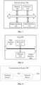
- an embodiment of the present application further provides a terminal device 600.
- the terminal device 600 may be the terminal device 400 in FIG. 4 , which can be configured to perform the operations corresponding to the terminal device in the method 200 shown in FIG. 2 .
- the terminal device 600 includes: an input interface 610, an output interface 620, a processor 630, and a memory 640.
- the input interface 610, the output interface 620, the processor 630, and the memory 640 may be connected through a bus system.
- the memory 640 is configured to store programs, instructions or codes.
- the processor 630 is configured to execute programs, instructions, or codes in the memory 640 to control the input interface 610 to receive signals, control the output interface 620 to send signals, and perform operations in the foregoing method embodiments.
- the processor 630 may be a central processing unit (CPU), and the processor 630 may also be other general-purpose processors or digital signal processors (DSP), application specific integrated circuit (ASIC), field programmable gate array (FPGA), or other programmable logic devices, discrete gate or transistor logic devices, discrete hardware components, and the like.
- DSP digital signal processors
- ASIC application specific integrated circuit
- FPGA field programmable gate array
- the general-purpose processor may be a microprocessor, or the processor may also be any conventional processor or the like.
- the memory 640 may include a read-only memory and a random access memory, and provide instructions and data to the processor 630. A portion of the memory 640 may also include non-volatile random access memory. For example, the memory 640 may also store device type information.
- each operation of the above method may be completed by an integrated logic circuit of hardware in the processor 630 or instructions in the form of software.
- the content of the method disclosed in conjunction with the embodiments of the present application may be directly embodied and executed by a hardware processor, or may be executed and completed by a combination of hardware and software modules in the processor.
- the software module may be located in a mature storage medium in the art, such as random access memory, flash memory, read-only memory, programmable read-only memory, or electrically erasable programmable memory, and registers.
- the storage medium is located in the memory 640, and the processor 630 reads information from the memory 640 and performs operations of the above method in combination with its hardware. In order to avoid repetition, they will not be described in detail here.
- the determining module 410 included in the terminal device 400 in FIG. 4 may be implemented by the processor 630 in FIG. 6
- the demodulating module 420 included in the terminal device 400 in FIG. 4 may be implemented by the input interface 610 and the output interface 620 in FIG. 6 .
- an embodiment of the present application further provides a network device 700.
- the network device 700 may be the network device 500 in FIG. 5 , which can be configured to perform operations corresponding to the network device in the method 300 shown in FIG. 3 .
- the network device 700 includes an input interface 710, an output interface 720, a processor 730, and a memory 740.
- the input interface 710, the output interface 720, the processor 730, and the memory 740 may be connected through a bus system.
- the memory 740 is configured to store programs, instructions or codes.
- the processor 730 is configured to execute programs, instructions, or codes in the memory 740 to control the input interface 710 to receive signals, control the output interface 720 to send signals, and perform operations in the foregoing method embodiments.
- the processor 730 may be a central processing unit (CPU), and the processor 730 may also be other general-purpose processors or digital signal processors (DSP), application specific integrated circuit (ASIC), field programmable gate array (FPGA), or other programmable logic devices, discrete gate or transistor logic devices, discrete hardware components, and the like.
- DSP digital signal processor
- ASIC application specific integrated circuit
- FPGA field programmable gate array
- the general-purpose processor may be a microprocessor, or the processor may also be any conventional processor or the like.
- the memory 740 may include a read-only memory and a random access memory, and provide instructions and data to the processor 730. A portion of the memory 740 may also include non-volatile random access memory. For example, the memory 740 may also store device type information.
- each operation of the above method may be completed by an integrated logic circuit of hardware in the processor 730 or instructions in the form of software.
- the content of the method disclosed in conjunction with the embodiments of the present application may be directly embodied and executed by a hardware processor, or may be executed and completed by a combination of hardware and software modules in the processor.
- the software module may be located in a mature storage medium in the art, such as random access memory, flash memory, read-only memory, programmable read-only memory, or electrically erasable programmable memory, and registers.
- the storage medium is located in the memory 740, and the processor 730 reads the information from the memory 740 and performs operations of the above method in combination with its hardware. In order to avoid repetition, they will not be described in detail here.
- the determining module 510 included in the network device 500 in FIG. 5 may be implemented by the processor 730 in FIG. 7
- the communicating module 520 included in the network device 500 in FIG. 5 may be implemented by the input interface 710 and the output interface 720 in FIG. 7 .
- FIG. 8 is a block diagram illustrating a chip according to an embodiment of the present application.
- the chip 800 shown in FIG. 8 includes a processor 810, and the processor 810 can call and run a computer program from a memory to implement the method in the embodiment of the present application.
- the chip 800 may further include a memory 820.
- the processor 810 can call and run a computer program from the memory 820 to implement the method in the embodiments of the present application.
- the memory 820 may be a separate device independent of the processor 810, or may be integrated in the processor 810.
- the chip 800 may further include an input interface 830.
- the processor 810 can control the input interface 830 to communicate with other devices or chips. Specifically, it can obtain information or data sent by other devices or chips.
- the chip 800 may further include an output interface 840.
- the processor 810 can control the output interface 840 to communicate with other devices or chips. Specifically, it can output information or data to other devices or chips.
- the chip may be applied to the network device in the embodiment of the present application, and the chip may implement the corresponding process implemented by the network device in each method of the embodiment of the present application. Details will be omitted here for the sake of brevity.
- the chip can be applied to the mobile terminal / terminal device in the embodiments of the present application, and the chip can implement the corresponding process implemented by the mobile terminal / terminal device in each method of the embodiments of the present application. Details will be omitted here for the sake of brevity.
- chips mentioned in the embodiments of the present application may also be referred to as system-on-chips, system chips, chip systems, or system-on-chip chips.
- FIG. 9 is a block diagram illustrating a communication system 900 according to an embodiment of the present application. As shown in FIG. 8 , the communication system 900 includes a terminal device 910 and a network device 920.
- the terminal device 910 may be configured to implement the functions corresponding to the terminal device in the above method
- the network device 920 may be configured to implement the functions implemented corresponding to the network device in the above method.
- the processor in the embodiment of the present application may be an integrated circuit chip, which has signal processing capabilities.
- each step of the foregoing method embodiment may be completed by an integrated logic circuit of hardware in a processor or instructions in the form of software.
- the foregoing processor may be a general-purpose processor, a digital signal processor (DSP), an application specific integrated circuit (ASIC), a field programmable gate array (FPGA), or other available programming logic devices, discrete gates or transistor logic devices, discrete hardware components.
- DSP digital signal processor
- ASIC application specific integrated circuit
- FPGA field programmable gate array
- the methods, steps, and logical block diagrams disclosed in the embodiments of the present application may be implemented or executed.
- the general-purpose processor may be a microprocessor or the processor may be any conventional processor or the like.
- the steps of the method disclosed in conjunction with the embodiments of the present application may be directly embodied and executed by a hardware decoding processor, or may be executed and completed by a combination of hardware and software modules in the decoding processor.
- the software module may be located in a mature storage medium in the art, such as random access memory, flash memory, read-only memory, programmable read-only memory, or electrically erasable programmable memory, and registers.
- the storage medium is located in the memory, and the processor reads the information from the memory and perform the steps of the above method in combination with its hardware.
- the memory in the embodiments of the present application may be volatile memory or non-volatile memory, or may include both volatile and non-volatile memory.
- the non-volatile memory may be read-only memory (ROM), programmable read-only memory (PROM), erasable programmable read-only memory (EPROM), electronically erasable programmable read only memory (EEPROM) or flash memory.
- ROM read-only memory
- PROM programmable read-only memory
- EPROM erasable programmable read-only memory
- EEPROM electronically erasable programmable read only memory
- flash memory may be a random access memory (RAM), which is used as an external cache.
- RAM random access memory
- SRAM static random access memory
- DRAM dynamic random access memory
- SDRAM synchronous dynamic random access memory
- DDR SDRAM double data rate synchronous dynamic random access memory
- ESDRAM enhanced synchronous dynamic random access memory
- SLDRAM synchronous connection dynamic random access memory
- DR RAM direct memory bus random access memory
- the memory in the embodiments of the present application may also be static random access memory (SRAM), dynamic random access memory (DRAM), Synchronous dynamic random access memory (SDRAM), double data rate synchronous dynamic random access memory (DDR SDRAM), enhanced synchronous dynamic random access memory (ESDRAM), synchronous connection Dynamic random access memory (SLDRAM) and direct memory bus random access memory (DR RAM), and the like. That is to say, the memories in the embodiments of the present application are intended to include but are not limited to these and any other suitable types of memories.
- SRAM static random access memory
- DRAM dynamic random access memory
- SDRAM Synchronous dynamic random access memory
- DDR SDRAM double data rate synchronous dynamic random access memory
- ESDRAM enhanced synchronous dynamic random access memory
- SLDRAM synchronous connection Dynamic random access memory
- DR RAM direct memory bus random access memory
- Embodiments of the present application also provide a computer-readable storage medium that stores one or more programs, the one or more programs include instructions which, when being executed by a portable electronic device that includes multiple application programs, causes the portable electronic device to perform the method according to the embodiments shown in FIGs. 2 and 3 .
- An embodiment of the present application also proposes a computer program including instructions.
- the computer program When the computer program is executed by a computer, the computer can execute the corresponding operations of the method in the embodiments shown in FIGs. 2 and 3 .
- the disclosed system, device, and method may be implemented in other ways.
- the device embodiments described above are only schematic.
- the division of the units is only a division of logical functions.
- there may be other divisions for example, multiple units or components may be combined or integrated into another system, or some features can be ignored or not implemented.
- the displayed or discussed mutual coupling or direct coupling or communication connection may be indirect coupling or communication connection through some interfaces, devices or units, and may be in electrical, mechanical or other forms.
- the units described as separate components may be or may not be physically separated, and the components displayed as units may be or may not be physical units, that is, they may be located in one place, or may be distributed at multiple network units. Some or all of the units may be selected according to actual needs to achieve the purpose of the solution of this embodiment.
- each functional unit in each embodiment of the present application may be integrated into one processing unit, or each unit may exist alone physically, or two or more units may be integrated into one unit.
- the functions are implemented in the form of software functional units and sold or used as independent products, they can be stored in a computer-readable storage medium.
- the technical solution of the present application may be essentially or a part that contributes to the existing technology or a part of the technical solution may be embodied in the form of a software product, the computer software product is stored in a storage medium, including several instructions to enable a computer device (which may be a personal computer, server, or network device, and the like) to perform all or part of the steps of the methods described in the embodiments of the present application.
- the foregoing storage medium may include U disk, mobile hard disk, read-only memory (ROM), random access memory (RAM), magnetic disk or optical disk and other media that can store program codes.
Landscapes
- Engineering & Computer Science (AREA)
- Signal Processing (AREA)
- Computer Networks & Wireless Communication (AREA)
- Mobile Radio Communication Systems (AREA)
- Communication Control (AREA)
- Small-Scale Networks (AREA)
- Traffic Control Systems (AREA)
Applications Claiming Priority (3)
| Application Number | Priority Date | Filing Date | Title |
|---|---|---|---|
| PCT/CN2018/071371 WO2019134096A1 (zh) | 2018-01-04 | 2018-01-04 | 车联网中用于传输数据的方法、终端设备和网络设备 |
| EP18898537.8A EP3726901B1 (en) | 2018-01-04 | 2018-08-16 | Method for transmitting data in internet of vehicles, terminal device and network device |
| PCT/CN2018/100790 WO2019134370A1 (zh) | 2018-01-04 | 2018-08-16 | 车联网中用于传输数据的方法、终端设备和网络设备 |
Related Parent Applications (2)
| Application Number | Title | Priority Date | Filing Date |
|---|---|---|---|
| EP18898537.8A Division-Into EP3726901B1 (en) | 2018-01-04 | 2018-08-16 | Method for transmitting data in internet of vehicles, terminal device and network device |
| EP18898537.8A Division EP3726901B1 (en) | 2018-01-04 | 2018-08-16 | Method for transmitting data in internet of vehicles, terminal device and network device |
Publications (1)
| Publication Number | Publication Date |
|---|---|
| EP4192171A1 true EP4192171A1 (en) | 2023-06-07 |
Family
ID=67143537
Family Applications (2)
| Application Number | Title | Priority Date | Filing Date |
|---|---|---|---|
| EP23154180.6A Pending EP4192171A1 (en) | 2018-01-04 | 2018-08-16 | Method for transmitting data in internet of vehicles, terminal device and network device |
| EP18898537.8A Active EP3726901B1 (en) | 2018-01-04 | 2018-08-16 | Method for transmitting data in internet of vehicles, terminal device and network device |
Family Applications After (1)
| Application Number | Title | Priority Date | Filing Date |
|---|---|---|---|
| EP18898537.8A Active EP3726901B1 (en) | 2018-01-04 | 2018-08-16 | Method for transmitting data in internet of vehicles, terminal device and network device |
Country Status (12)
| Country | Link |
|---|---|
| US (1) | US20200336276A1 (es) |
| EP (2) | EP4192171A1 (es) |
| JP (1) | JP7282094B2 (es) |
| KR (1) | KR20200106520A (es) |
| CN (2) | CN111602439A (es) |
| AU (1) | AU2018399356B2 (es) |
| BR (1) | BR112020013675A2 (es) |
| CA (1) | CA3087605C (es) |
| ES (1) | ES2942004T3 (es) |
| MX (1) | MX2020007065A (es) |
| TW (1) | TWI805673B (es) |
| WO (2) | WO2019134096A1 (es) |
Families Citing this family (7)
| Publication number | Priority date | Publication date | Assignee | Title |
|---|---|---|---|---|
| EP3739794B1 (en) | 2018-01-22 | 2022-08-24 | Guangdong Oppo Mobile Telecommunications Corp., Ltd. | Information determining method, device, and computer storage medium |
| US11470613B2 (en) * | 2018-03-30 | 2022-10-11 | Lg Electronics Inc. | Method for transmitting or receiving sidelink signal by terminal in wireless communication system supporting sidelink and apparatus therefor |
| US11133970B2 (en) * | 2018-09-27 | 2021-09-28 | Qualcomm Incorporated | Techniques for supporting multiple waveforms in wireless communications |
| EP3648387B1 (en) * | 2018-10-31 | 2022-01-19 | Mitsubishi Electric R&D Centre Europe B.V. | Selection of rs patterns for d2d communications |
| KR20200087630A (ko) * | 2019-01-11 | 2020-07-21 | 주식회사 아이티엘 | 무선통신 시스템에서 dmrs 구성 방법 및 장치 |
| CN114826518A (zh) * | 2021-01-29 | 2022-07-29 | 北京紫光展锐通信技术有限公司 | 参考信号图案的确定方法及装置 |
| EP4075709A1 (en) * | 2021-04-16 | 2022-10-19 | Nokia Technologies Oy | Decoding path generation |
Citations (3)
| Publication number | Priority date | Publication date | Assignee | Title |
|---|---|---|---|---|
| WO2017026975A1 (en) * | 2015-08-12 | 2017-02-16 | Intel Corporation | Demodulation in wireless communications |
| WO2017178993A1 (en) * | 2016-04-12 | 2017-10-19 | Telefonaktiebolaget Lm Ericsson (Publ) | Method and an apparatus for reference signal mapping for sidelink communications |
| WO2020033704A1 (en) * | 2018-08-08 | 2020-02-13 | Idac Holdings, Inc. | Enhanced sidelink control transmission |
Family Cites Families (20)
| Publication number | Priority date | Publication date | Assignee | Title |
|---|---|---|---|---|
| CN101043718B (zh) * | 2006-03-24 | 2011-09-14 | 电信科学技术研究院 | 一种用下行共享物理信道进行寻呼的方法 |
| JP5108786B2 (ja) * | 2006-12-26 | 2012-12-26 | 富士通株式会社 | 無線通信方法並びに無線制御局及び無線基地局 |
| CN102149082B (zh) * | 2010-02-05 | 2014-11-26 | 中国移动通信集团公司 | 一种终端专用解调参考信号的指示方法、装置及系统 |
| CN103873215B (zh) * | 2012-12-17 | 2017-12-05 | 中兴通讯股份有限公司 | 增强物理混合自动重传请求指示信道传输方法及装置 |
| CN108111291B (zh) * | 2013-01-25 | 2021-08-20 | 华为技术有限公司 | 解调参考信号传输装置和计算机可读存储介质 |
| EP2941080B1 (en) * | 2013-01-25 | 2018-04-25 | Huawei Technologies Co., Ltd. | Transmission of demodulation reference signals in a new carrier type |
| CN104322090A (zh) * | 2013-04-02 | 2015-01-28 | 华为技术有限公司 | 专用信道传输方法及装置 |
| CN104125186B (zh) * | 2013-04-28 | 2019-08-30 | 中兴通讯股份有限公司 | 一种解调参考信号图样信息的选取方法、系统及装置 |
| CN106105085A (zh) * | 2014-03-19 | 2016-11-09 | Lg电子株式会社 | 在无线通信系统中发送和接收设备到设备ue信号的方法及其装置 |
| CN107113894B (zh) * | 2015-04-03 | 2020-11-10 | 华为技术有限公司 | 数据传输的方法、用户设备和基站 |
| WO2016195411A1 (ko) * | 2015-06-03 | 2016-12-08 | 엘지전자 주식회사 | 무선 통신 시스템에서 v2v 통신을 위한 참조 신호 설정 방법 및 이를 위한 장치 |
| US10863492B2 (en) * | 2015-07-16 | 2020-12-08 | Qualcomm Incorporated | Low latency device-to-device communication |
| CN107925533B (zh) * | 2015-09-24 | 2022-06-17 | 苹果公司 | 高速环境中的v2x性能增强 |
| CN111867043B (zh) * | 2015-09-24 | 2022-08-09 | 华为技术有限公司 | 同步方法、用户设备和基站 |
| DE102015116247B4 (de) * | 2015-09-25 | 2021-01-21 | Apple Inc. | Verfahren zum Ausführen von Kommunikationen, mobile Endgeräte und Basisbandmodems |
| CN108141336B (zh) * | 2015-09-29 | 2020-10-30 | Lg电子株式会社 | 用于接收dci的方法和ue以及用于发送dci的方法和基站 |
| CN105634707B (zh) * | 2015-12-31 | 2019-04-23 | 深圳市金立通信设备有限公司 | 一种信息传输的方法、基站及终端 |
| JP6696192B2 (ja) * | 2016-02-04 | 2020-05-20 | ソニー株式会社 | 通信装置および通信方法 |
| CN107046457B (zh) * | 2016-02-05 | 2020-02-11 | 中国移动通信集团公司 | 业务信息的发送方法、接收方法及终端 |
| US10425959B2 (en) * | 2016-05-13 | 2019-09-24 | Samsung Electronics Co., Ltd. | Method and device for transmitting data |
-
2018
- 2018-01-04 WO PCT/CN2018/071371 patent/WO2019134096A1/zh active Application Filing
- 2018-08-16 BR BR112020013675-1A patent/BR112020013675A2/pt unknown
- 2018-08-16 EP EP23154180.6A patent/EP4192171A1/en active Pending
- 2018-08-16 CN CN201880084893.9A patent/CN111602439A/zh active Pending
- 2018-08-16 EP EP18898537.8A patent/EP3726901B1/en active Active
- 2018-08-16 JP JP2020537001A patent/JP7282094B2/ja active Active
- 2018-08-16 CN CN202010899202.XA patent/CN112054886B/zh active Active
- 2018-08-16 MX MX2020007065A patent/MX2020007065A/es unknown
- 2018-08-16 KR KR1020207022488A patent/KR20200106520A/ko not_active Application Discontinuation
- 2018-08-16 AU AU2018399356A patent/AU2018399356B2/en active Active
- 2018-08-16 ES ES18898537T patent/ES2942004T3/es active Active
- 2018-08-16 WO PCT/CN2018/100790 patent/WO2019134370A1/zh active Application Filing
- 2018-08-16 CA CA3087605A patent/CA3087605C/en active Active
-
2019
- 2019-01-03 TW TW108100250A patent/TWI805673B/zh active
-
2020
- 2020-07-06 US US16/921,667 patent/US20200336276A1/en active Pending
Patent Citations (3)
| Publication number | Priority date | Publication date | Assignee | Title |
|---|---|---|---|---|
| WO2017026975A1 (en) * | 2015-08-12 | 2017-02-16 | Intel Corporation | Demodulation in wireless communications |
| WO2017178993A1 (en) * | 2016-04-12 | 2017-10-19 | Telefonaktiebolaget Lm Ericsson (Publ) | Method and an apparatus for reference signal mapping for sidelink communications |
| WO2020033704A1 (en) * | 2018-08-08 | 2020-02-13 | Idac Holdings, Inc. | Enhanced sidelink control transmission |
Non-Patent Citations (1)
| Title |
|---|
| SONY: "Discussion on DMRS enhancement and operation for V2V", vol. RAN WG1, no. Busan, Korea; 20160411 - 20160415, 1 April 2016 (2016-04-01), XP051079618, Retrieved from the Internet <URL:http://www.3gpp.org/ftp/tsg_ran/WG1_RL1/TSGR1_84b/Docs/> [retrieved on 20160401] * |
Also Published As
| Publication number | Publication date |
|---|---|
| CA3087605A1 (en) | 2019-07-11 |
| CN112054886B (zh) | 2022-03-25 |
| US20200336276A1 (en) | 2020-10-22 |
| AU2018399356B2 (en) | 2023-12-14 |
| WO2019134096A1 (zh) | 2019-07-11 |
| ES2942004T3 (es) | 2023-05-29 |
| TW201931879A (zh) | 2019-08-01 |
| CN111602439A (zh) | 2020-08-28 |
| KR20200106520A (ko) | 2020-09-14 |
| EP3726901B1 (en) | 2023-03-15 |
| BR112020013675A2 (pt) | 2020-12-01 |
| MX2020007065A (es) | 2020-09-09 |
| EP3726901A4 (en) | 2021-01-27 |
| CA3087605C (en) | 2024-01-23 |
| JP2021510035A (ja) | 2021-04-08 |
| WO2019134370A1 (zh) | 2019-07-11 |
| AU2018399356A1 (en) | 2020-08-06 |
| EP3726901A1 (en) | 2020-10-21 |
| CN112054886A (zh) | 2020-12-08 |
| JP7282094B2 (ja) | 2023-05-26 |
| TWI805673B (zh) | 2023-06-21 |
| WO2019134370A8 (zh) | 2020-08-06 |
Similar Documents
| Publication | Publication Date | Title |
|---|---|---|
| EP3726901B1 (en) | Method for transmitting data in internet of vehicles, terminal device and network device | |
| JP7167250B2 (ja) | 時間周波数リソースの伝送方向を構成するための方法、および装置 | |
| EP3493501B1 (en) | Signal sending method, network device and terminal device | |
| JP7181885B2 (ja) | 同期信号を伝送するための方法及び装置 | |
| EP3648389A1 (en) | Communication method, network device, and relay device | |
| TW202008828A (zh) | 資源配置的方法和終端設備 | |
| US20220256487A1 (en) | Rate matching indication method and apparatus, and device and storage medium | |
| JP7065972B2 (ja) | ページング方法、ネットワークデバイス及び端末デバイス | |
| WO2021159344A1 (zh) | 一种同步信号块的发送方法、接收方法及装置 | |
| TW202013919A (zh) | 一種資料傳輸方法、終端設備及網路設備 | |
| CN115065987B (zh) | 空闲信道侦听方法、装置及设备 | |
| JP7113030B6 (ja) | 間欠受信用の方法及び装置 | |
| JP6624605B2 (ja) | ダウンリンク伝送方法および装置 | |
| CN116406498A (zh) | 一种通信方法及装置 | |
| JP6896846B2 (ja) | システム情報の伝送方法、ネットワークデバイスおよび端末デバイス | |
| CN110972295B (zh) | 一种通信方法及设备 | |
| US20230379121A1 (en) | Method performed by user equipment, and user equipment | |
| CN113785652A (zh) | 执行随机接入过程的系统和方法 | |
| CN115696591A (zh) | 一种资源确定方法及通信装置 | |
| CN114342520A (zh) | 系统信息的传输方法和通信装置 | |
| KR20220044975A (ko) | 향상된 랜덤 액세스 절차의 시스템 및 방법 |
Legal Events
| Date | Code | Title | Description |
|---|---|---|---|
| PUAI | Public reference made under article 153(3) epc to a published international application that has entered the european phase |
Free format text: ORIGINAL CODE: 0009012 |
|
| STAA | Information on the status of an ep patent application or granted ep patent |
Free format text: STATUS: THE APPLICATION HAS BEEN PUBLISHED |
|
| AC | Divisional application: reference to earlier application |
Ref document number: 3726901 Country of ref document: EP Kind code of ref document: P |
|
| AK | Designated contracting states |
Kind code of ref document: A1 Designated state(s): AL AT BE BG CH CY CZ DE DK EE ES FI FR GB GR HR HU IE IS IT LI LT LU LV MC MK MT NL NO PL PT RO RS SE SI SK SM TR |
|
| STAA | Information on the status of an ep patent application or granted ep patent |
Free format text: STATUS: REQUEST FOR EXAMINATION WAS MADE |
|
| 17P | Request for examination filed |
Effective date: 20231206 |
|
| RBV | Designated contracting states (corrected) |
Designated state(s): AL AT BE BG CH CY CZ DE DK EE ES FI FR GB GR HR HU IE IS IT LI LT LU LV MC MK MT NL NO PL PT RO RS SE SI SK SM TR |