EP4189441B1 - Multifunktions-gammastrahlungsdetektor - Google Patents
Multifunktions-gammastrahlungsdetektor Download PDFInfo
- Publication number
- EP4189441B1 EP4189441B1 EP21746155.7A EP21746155A EP4189441B1 EP 4189441 B1 EP4189441 B1 EP 4189441B1 EP 21746155 A EP21746155 A EP 21746155A EP 4189441 B1 EP4189441 B1 EP 4189441B1
- Authority
- EP
- European Patent Office
- Prior art keywords
- detection
- detector
- optical
- detection head
- head
- Prior art date
- Legal status (The legal status is an assumption and is not a legal conclusion. Google has not performed a legal analysis and makes no representation as to the accuracy of the status listed.)
- Active
Links
Images


Classifications
-
- G—PHYSICS
- G01—MEASURING; TESTING
- G01T—MEASUREMENT OF NUCLEAR OR X-RADIATION
- G01T1/00—Measuring X-radiation, gamma radiation, corpuscular radiation, or cosmic radiation
- G01T1/16—Measuring radiation intensity
- G01T1/161—Applications in the field of nuclear medicine, e.g. in vivo counting
-
- A—HUMAN NECESSITIES
- A61—MEDICAL OR VETERINARY SCIENCE; HYGIENE
- A61B—DIAGNOSIS; SURGERY; IDENTIFICATION
- A61B6/00—Apparatus or devices for radiation diagnosis; Apparatus or devices for radiation diagnosis combined with radiation therapy equipment
- A61B6/42—Arrangements for detecting radiation specially adapted for radiation diagnosis
- A61B6/4208—Arrangements for detecting radiation specially adapted for radiation diagnosis characterised by using a particular type of detector
- A61B6/4258—Arrangements for detecting radiation specially adapted for radiation diagnosis characterised by using a particular type of detector for detecting non x-ray radiation, e.g. gamma radiation
-
- G—PHYSICS
- G01—MEASURING; TESTING
- G01T—MEASUREMENT OF NUCLEAR OR X-RADIATION
- G01T1/00—Measuring X-radiation, gamma radiation, corpuscular radiation, or cosmic radiation
- G01T1/16—Measuring radiation intensity
- G01T1/161—Applications in the field of nuclear medicine, e.g. in vivo counting
- G01T1/164—Scintigraphy
- G01T1/1641—Static instruments for imaging the distribution of radioactivity in one or two dimensions using one or several scintillating elements; Radio-isotope cameras
- G01T1/1642—Static instruments for imaging the distribution of radioactivity in one or two dimensions using one or several scintillating elements; Radio-isotope cameras using a scintillation crystal and position sensing photodetector arrays, e.g. ANGER cameras
Definitions
- the present invention relates to a multifunction gamma radiation detector which can be widely applied in the field of radio-guided surgery (intraoperative and laparoscopic) for locating lymph nodes and tumours and/or other pathologies.
- gamma detectors are instruments used to locate tumour cells or specific pathologies in a patient by picking up the radiation emitted by a radiopharmaceutical previously administered to the patient and which tends to concentrate in the cells affected by those pathologies.
- gamma detectors comprise a detection head equipped with a single crystal or a plurality of crystals suitably oriented and configured to absorb the gamma rays emitted by the radiopharmaceutical.
- the prior art scintigraphic detectors also comprise a rod configured to receive at one end the detection head and at a further end a handgrip configured for suitably directing the detection head during the medical application.
- gamma detectors are known the detection head of which is made of a material with a high atomic number and has a plurality of detection elements each comprising a scintillation crystal. These crystals are distinct from each other and aligned according to respective different collimation axes for simultaneously detecting gamma radiation directed in different directions.
- Each detection element is preferably associated with a collimator suitable to screen the gamma radiation striking on the detection element with an external angle to a predetermined external solid angle.
- These detectors usually have an axial collimator and at least two lateral collimators, inclined with respect to the axial collimator in such a way that the central crystal acts as a true and proper detector whilst the lateral crystals act as direction sensors to indicate to the operator where to direct the instrument during the medical analysis.
- detectors the head of which comprises, in addition to scintillation crystals, optical devices such as, for example, video cameras which provide a visual image of the zone affected by the pathology.
- detectors which are equipped with a plurality of detection elements the collimation axes of which extend parallel to the development axis of the head and with a camera/video camera located in a central portion of the head in place of the central scintigraphic crystal.
- Prior art gamma detectors the detection elements of which are configured to locate a zone affected by a pathology and wherein the camera/video camera is designed to contribute to the accelerating of the operations for locating the zone affected by the pathology, as for example, shown in US6643538B1 .
- Prior art detectors disadvantageously have drawbacks linked to the precision, the cost and the poor versatility thereof.
- a further drawback relates to the fact that these detectors have solid detection angles with amplitudes that are insufficient to perform an angular detection over a large area, thus penalising the detection speed which requires a greater skill of the operator and/or implies a greater number of manoeuvres performed by the operator to trace the correct aligned position of the detection head with the source of emission and therefore with the zone affected by the pathology.
- prior art detectors do not have arrangements of the detection elements and the optical device which are favourable to a precise and rapid analysis of the part of the patient affected by the pathology.
- a further drawback derives from the fact that the known detectors have poor operational flexibility, since the application thereof is limited to the specific use for the identification of the position of a tumour and/or other pathologies and, in the case of different uses, it is necessary to have available additional instrumentation with a considerable increase in costs.
- these devices are not able to allow an in vivo analysis of the zone identified by the detection elements as the zone affected by the pathology, since they are not able to provide information regarding the chemical composition and/or the structure of the zone. It is not, for example, possible, by means of known detectors, to perform an assessment of the wounded/affected tissue in order to focus more accurately on the possible excision of the part.
- prior art gamma detectors as they are not able to provide in vivo information regarding the nature of the pathology, always implicate, after the localisation of the pathology, the intervention on the patient of further instrumentation, making the medical analysis rather invasive, long and expensive.
- the technical purpose of the present invention is therefore to provide a multifunction gamma radiation detector which is able to obviate the drawbacks of the prior art.
- the aim of the present invention is to provide a gamma detector which, once the zone of the patient affected by the pathology has been located, is able to perform an in vivo analysis of the nature of the pathology during radio-guided surgery.
- a further aim of the present invention is to provide a gamma detector which allows a precise and fast localisation of the zone affected by the pathology.
- the aim of the present invention is to provide a gamma detector which is extremely precise and reliable.
- a further aim of the present invention is to provide a gamma detector which is extremely versatile in use.
- a further aim of the present invention is to provide a gamma detector having dimensions also compatible with a laparoscopic use in a trocar.
- a multifunction gamma radiation detector as claimed in claim 1 comprising a supporting rod, a detection head coupled or integrated with a first end of the supporting rod and comprising a plurality of detection elements which are separate from each other for simultaneously detecting gamma radiation directed along respective directions.
- Each detection element comprises at least one scintillation crystal and a corresponding first electronic conversion circuitry for receiving an optical signal from the crystal and converting it into an electrical signal, each of the detection elements is further associated with a respective collimator made of a material with a high atomic number and designed to screen the gamma radiation striking on the detection element with an external angle and a predetermined solid angle.
- the multifunction gamma radiation detector according to the present invention further comprises a handgrip connected or connectable to a second end of the supporting rod and which can be manually gripped by an operator to direct the detector and a second electronic circuitry for converting and/or treating the signals, preferably arranged inside the handgrip, connected to the first electronic conversion device for processing the electrical signal generated by the first electronic conversion circuitry.
- the detector according to the present invention is characterised in that the detection head also comprises at least one optical detection device configured to acquire a sequence of optical signals emitted by a suitably energised body tissue and in that the detection elements are angularly distributed on the detection head around the at least one optical detection device.
- the optical detection device can preferably be selected from among: micro-structured fibres; a phoswitch; an optical system for holographic microscopy.
- the optical detection device has an optical detection axis parallel to or coinciding with a longitudinal axis of extension of the detection head while the detection elements have respective collimation axes which are inclined relative to the optical detection axis, preferably by an angle of between 0° and 90°.
- the detection elements have respective collimation axes that diverge out from the detection head.
- the respective collimation axes of the detection elements converge out from the detection head.
- the multifunction gamma radiation detector allows in vivo analyses to be performed on the nature and composition of the pathology detected during the analysis.
- the optical detection device allows data to be obtained relating to the nature and structure of the localised pathology thereby providing a first base for medical diagnosis without the need to introduce further medical instrumentation in the patient and/or without the need to perform an excision of the affected zone.
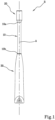
- R denotes a multifunction gamma radiation detector according to the present invention.
- the detector “R” comprises a supporting rod 10, a detection head 20 coupled or integrated to a first end 10a of the supporting rod 10 and a handgrip 30 connected to or connectable to a second end 10b of the supporting rod 10 and which can be manually gripped by an operator to direct the detector "R” during a medical analysis.
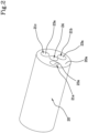
- the supporting head 20 is made in the form of a solid body having a cylindrical shape preferably extending along a longitudinal axis of extension "A" and having a flat front surface 20a also perpendicular to the longitudinal axis of extension "A".
- solid body is used to mean a block made of a single material.
- the detection head 20 is made of a material with a high atomic number, for example lead, designed to absorb and screen the gamma radiation emitted by a radiopharmaceutical.
- the solid body comprises a plurality of detection elements 21a, 21b, 21c distinct from each other for simultaneously detecting gamma radiation directed along respective directions different to each other.
- the detection head 20 comprises three detection elements 21a, 21b, 21c angularly spaced from each other by an angle having an amplitude, measured on the plane defined by the front surface 20a of the detection head 20, equal to 120°.
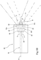
- each detection element 21a, 21b, 21c comprises at least one scintillation crystal 22 and a corresponding first electronic conversion circuitry (not illustrated) for receiving an optical signal from the scintillation crystal 22 and converting it into an electric signal.
- the scintillation crystals 22 are sensitive to gamma radiation having energy of between 0 keV and 250 keV.
- each detection element 21a, 21b, 21c is also associated with a respective collimator 23.
- each collimator 23 comprises a detection channel made of the same material as the detection head 22.
- Each collimator 23 has a respective opening 23a lying on the front surface 20a of the detection head 20 and a bottom on which the scintillation crystal 22 lies in such a way that a portion of the lateral wall of the detection channel, comprised between the crystal 22 and the external opening 23a of the channel, defines a solid detection angle ⁇ , ⁇ , ⁇ and thus determines the collimation of the radiation directed towards the crystal 22.
- each collimator 23 is made of a material with a high atomic number and is therefore suitable to screen the gamma radiation striking on the detection element 21a, 21b, 21c with an external angle to the solid angle ⁇ , ⁇ , ⁇ defined by the respective collimator 23. In this way, only gamma radiation having an angle within the solid detection angle ⁇ , ⁇ , can be effectively absorbed by the scintillation crystal 22 and converted, by the first electronic conversion circuitry, into an electrical signal.
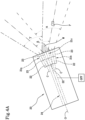
- the detection elements 21a, 21b, 21c also define respective solid detection angles ⁇ , ⁇ , conformed and/or oriented in such a way as to define between them a blind zone "W" external of the solid detection angles ⁇ , ⁇ , ⁇ .
- the blind zone "W” is therefore projecting to a central portion of the front surface 20a of the detection head 20.
- the blind zone “W” extends for a length having a minimum value of approximately 5 mm and a maximum value, approximately equal to 50 mm.
- the length of the blind zone “W” is measured starting from the front surface 20a of the detection head 20 and its overall value varies on the basis of a configuration of the detection elements 21a, 21b, 21c on the detection head 20.
- the blind zone “W” may have a length of between zero and the above-mentioned minimum value while, in the case of a divergent configuration ( figure 3B ), the blind zone “W” may have a length of between zero and the above-mentioned maximum value.
- the blind zone “W” may extend up to a maximum of 5 mm from the front surface 20a, while on the other hand, in the case of a divergent configuration, the blind zone “W” may extend up to 50 mm, preferably up to 20 mm, from the front surface 20a of the detection head 20.
- This aspect of the present invention is particularly advantageous for precise and reliable localisation of the part of the patient affected by the pathology, as described in detail below.
- the detector “R” also comprises a handgrip 30 connected or connectable to a second end 10b of the supporting rod 10 and which can be gripped manually by an operator to direct the detector "R" during medical analysis.
- the handgrip 30 has a transversal dimension greater than the transversal dimension of the supporting rod 10 and is reversibly connectable to the second end 10b of the supporting rod 10 by a mechanical connector (not illustrated) equipped with electrical contacts.
- the detector "R” comprises a second electronic circuitry for converting and/or treating the signals connected to the first electronic conversion circuitry for processing the electric signal generated by the first electronic converter.
- the second electronic conversion circuitry converts the analog signals coming from each of the first electronic conversion circuitry into digital signals.
- the transfer of the signals coming from the first electronic conversion circuitry to the second electronic conversion circuitry takes place via the electrical contacts present in the mechanical connector of the handgrip 30.
- the mechanical connector it is advantageously possible to connect a plurality of supporting rods 10 having different detection heads 20 (for example, angled detection heads or heads for laparoscopic analysis) to the same handgrip 30 in a fast and easy manner.
- the second electronic conversion circuitry can therefore receive the signals coming from the first electronic conversion circuitry of the various detection heads 20 which can be applied on the handgrip 30. This aspect considerably reduces the costs of the multifunction gamma radiation detector "R" since only one second electronic conversion circuitry is sufficient to operate with different detection heads 20.
- the detection head 20 necessary for medical analysis is mounted on the handgrip 30 by means of the mechanical connector.
- the detection head 20 is inserted in a patient's cavity and oriented by the operator into that cavity in such a way that the detection elements 21a, 21b, 21c can absorb the gamma radiations at an internal angle of the solid angles ⁇ , ⁇ , ⁇ defined by the detection elements 21a, 21b, 21c.
- the gamma radiation absorbed by each detection element 21a, 21b, 21c are converted into electric signals by the first electronic conversion circuitry and then transferred to the second electronic conversion circuitry in such a way that the signals are digitalised.
- the detector “R” also comprises a processing and control unit (not illustrated) configured to receive and process the signals coming from the second electronic conversion circuitry.
- the processing and control unit is preferably connected to the second electronic conversion circuitry of the handgrip 30 by Wi-Fi, Bluetooth or via cable in such a way that the signals are transmitted from the second electronic conversion circuitry to the control unit.
- control unit comprises a monitor (not illustrated), which shows the operator the processing of the signals coming from the detector "R".
- the processing and control unit further comprises, integrated thereto, a sound signalling device (not illustrated) configured to emit an acoustic signal which is directional or at a different intensities/frequencies according to the detection element 21a, 21b, 21c most affected by the radiation at a given instant.
- a sound signalling device (not illustrated) configured to emit an acoustic signal which is directional or at a different intensities/frequencies according to the detection element 21a, 21b, 21c most affected by the radiation at a given instant.
- the processing and control unit also comprises a visual signalling device, for example a flashing LED, configured to emit a visual signal according to the detection element 21a, 21b, 21c struck most by the radiation at a given instant.
- a visual signalling device for example a flashing LED, configured to emit a visual signal according to the detection element 21a, 21b, 21c struck most by the radiation at a given instant.
- the use of the monitor together with the acoustic and/or visual signal thus constitutes a "navigating system" inside a patient's cavity.
- gamma radiation having different directions strikes the detection head 20 but only the radiations having directions falling within the solid angles ⁇ , ⁇ , ⁇ , defined by the detection elements 21a, 21b, 21c are effectively absorbed and converted into electric signals by the first electronic conversion circuitry. These electric signals are transmitted to the second electronic conversion circuitry in such a way as to be transformed into digital signals. The signals are then sent to the processing and control unit which analyses them, processes them and indicates to the operator where to direct the detection head 20.
- a value is derived that relates to a quantity of gamma rays absorbed.
- the gamma ray source that is to say, the zone affected by the pathology "P"
- the zone affected by the pathology "P” is outside the blind zone covered by the openings of the solid angles ⁇ , ⁇ , ⁇
- at least some detection elements 21a, 21b, 21c give rise to non-zero values.
- the zone affected by the pathology "P" is located in a zone comprised between the solid angles ⁇ , ⁇ described by only two detection elements 21b, 21c.
- the third detection element 21a does not absorb gamma radiation coming from the zone affected by the pathology "P” and therefore mainly records background noise, thus giving a non-significant value.
- the operator identifies (autonomously or by means of a suitable automatic audio-visual signal) an unbalancing of the overall reading of the detection elements 21a, 21b, 21c corresponding to a position of the detection head 20 which is not frontally aligned to the affected zone "P".
- the detection head 20 is then oriented in such a way that the source falls in the zone where the solid detection angles ⁇ , ⁇ , ⁇ intersect, that is to say, in the zone in which all the detection elements 21a, 21b, 21c simultaneously result in non-zero and homogeneous values.
- the detection head 20 is oriented in such a way as to be rotated in the direction of greatest origin of the gamma radiation.
- the operations for reading the values measured by the detection elements 21a, 21b, 21c and the consequent re-directing of the detection head 20 are then repeated until all the detection elements 21a, 21b, 21c obtain values which are homogeneous, that is, practically identical to each other (balancing of the readings of the individual detection elements 21a, 21b, 21c).
- the detection head 20 is arranged in such a way that the zone affected by the pathology "P" is comprised in the zone of intersection between the openings of each of the solid detection angles ⁇ , ⁇ , ⁇ .
- the detection head 20 is therefore aligned with the zone affected by the pathology "P" which is therefore located in a space in which all the solid angles ⁇ , ⁇ , described by the detection elements 21a, 21b, 21c intersect each other.
- the detection head 20 is moved towards the gamma ray source in an axial direction, that is to say, to the zone "P", until the values recorded for each detection element 21a, 21b, 21c are cancelled or reach a value below a predetermined threshold.
- the gamma ray source is in the blind zone "W" exactly located in front of the centre of the detection head 20.
- the relative position of the detection head 20 with respect to the zone affected by the pathology "P" is optimal for performing an optical imaging type analysis as described in detail below.
- the detection head 20 is also equipped with at least one movement sensor (not illustrated), preferably an accelerometer and/or a gyroscope, configured to acquire data relative to the instantaneous position of the detection head 20 in space.
- the movement sensor records the instantaneous position of the detection head 20 and transfers the position to the processing and control unit. This aspect is particularly advantageous since, once the part affected by the pathology has been located, the position sensor adjusts the position of the head 20 allowing the zone to be more quickly localised in the case of subsequent analyses.
- the head of the detector 20 of the present invention also comprises at least one optical detection device 24 configured to acquire a sequence of optical signals emitted by a body tissue suitably energised for example by light coming from the optical detection device 24 or by means of a contrast drug previously assumed by the patient.
- the optical detection device 24 can be selected from: micro-structured fibres; phoswitch; optical system for holographic microscopy.
- the optical detection device 24 advantageously makes it possible to acquire data relating to the nature, structure and composition of the zone affected by the pathology "P", thus facilitating a medical analysis by the operator.
- the optical detection device 24 advantageously makes it possible to obtain maps of biological structures which can, if necessary, be displayed on a monitor.
- the detection device 24 is not limited to providing images of the zone affected by the pathology but makes it possible to derive information useful for an in-situ analysis of the pathology.
- the optical detection device 24 occupies a central position of the detection head 20 whilst the detection elements are angularly distributed around it.
- This distribution on the detection head 20 advantageously makes it possible to quickly locate the part affected by the pathology thanks to the detection elements 21a, 21b, 21c and then to perform an in-situ analysis on the nature of the pathology that is precise and reliable.
- the detection elements 21a, 21b, 21c are angularly distributed on the detection head 20 about the optical detection device 24 in such a way as to form a "crown" about the optical detection device 24.
- the optical detection device 24 has an optical detection axis "O" parallel to or coinciding with the longitudinal axis of extension "A" of the detection head 20.
- the optical detection device 24 has preferably an optical detection axis "O” coinciding with the longitudinal axis of extension "A”.
- the optical detection device 24 has the optical detection axis "O" passing through the blind zone "W".
- the detection elements 21a, 21b, 21c have respective collimation axes "C" which are inclined relative to the optical detection axis "O".
- the collimation axes "C" of the detection elements 21a, 21b, 21c are preferably inclined at an angle of between 0° and 90° relative to the optical detection axis "O".
- the multifunction gamma radiation detector “R” is in effect able to locate the zone affected by the pathology "P" in a fast and precise manner, while, thanks to the presence of the optical detection device 24, the detector “R” is useful for carrying out in sharp analyses of the zone just identified.
- the multifunction scintigraphic detector "R” is inserted in a cavity of the patient in such a way that the detection elements 21a, 21b, 21c absorb the gamma radiation emitted by the zone affected by the pathology "P" and comprised in the solid angles ⁇ , ⁇ , ⁇ .
- the zone affected by pathology "P" is located in a zone comprised between the solid angles ⁇ , ⁇ described by only two detection elements 21b, 21c.
- the above-mentioned two detection elements 21b, 21c absorb the gamma radiation coming from the zone affected by pathology "P".
- the gamma radiation absorbed by these detection elements 21b, 21c are transformed into electric signals and processed by the processing and control unit which derives two significantly non-zero values therefrom.
- the third detection element 21a does not absorb gamma radiation coming from the zone affected by the pathology "P" and therefore mainly records background noise, thus giving a non-significant value.
- the processing and control unit thus indicates to the operator, for example via a monitor or by visual and/or acoustic signals, in which direction to direct the detection head 20.
- the detection head 20 is oriented in such a way as to be rotated in the direction of the greatest origin of the gamma radiation, that is to say, towards the zone indicated by the two most involved detection elements 21b, 21c.
- the detection head 20 is oriented towards the direction of greatest origin of the gamma rays, that is to say, the highest value of the detection head 20 is oriented in the direction indicated by the detection element 21a, 21b, 21c.
- All the detection elements 21a, 21b, 21c advantageously actively contribute to the localisation of the pathology in such a way as to allow an identification of the affected zone in a fast and reliable manner.
- the operations for reading the values measured by the detection elements 21a, 21b, 21c and the consequent re-directing of the detection head 20 are then repeated until all the detection elements 21a, 21b, 21c result in homogeneous values, that is to say, almost equal to each other.
- the detection head 20 is positioned in such a way that the zone affected by the pathology "P" is located in the zone of intersection between the openings of each of the solid detection angles ⁇ , ⁇ , ⁇ , that is to say, in the zone where all the detection elements 21a, 21b, 21c detect the same quantity of gamma radiation.
- the detection head 20 is thus aligned with the zone affected by the pathology "P".
- the detection head 20 is aligned with the zone affected by the pathology "P" along the optical detection axis "O".
- the detection head 20 is thus moved close to the source, that is to say, to the zone affected by the pathology "P".
- the values recorded by each detection element 21a, 21b, 21c diminish and are more homogeneous the more the approach is performed in an axial/longitudinal direction. This reduction is due to the fact that the more the detection signal 20 is neared to the zone affected by the pathology "P” the more it moves towards the end regions of the collimation fields of the detection elements 21a, 21b, 21c, moving more and more towards the blind zone "W", then definitively leaving the fields on reaching the blind zone "W".
- the zone affected by pathology "P" is aligned with a central portion of the detection head 20, i.e. aligned with the optical detection device 24.
- the decrease of the gamma radiation values absorbed by the detection elements 21a, 21b, 21c is advantageously exploited, i.e. the presence of the blind zone "W” is used.
- This situation therefore guarantees both the fact that the zone affected by the pathology "P” is exactly aligned with the optical detection axis "O" of the optical detection device 24 and the fact that it is located at a minimal distance from a central zone of the front surface 20a of the detection head 20.
- the optical detection device 24 may be activated to carry out an optical type analysis of the optical imaging type.
- the position of the detection head 20 relative to the zone affected by the pathology "P" is advantageously optimal for carrying out the subsequent optical type analyses since the zone affected by the pathology "P" is at a minimum distance from the front surface 20a of the detection head 20 and is also centred relative to the detection head 20 along the optical detection axis "O".
- the purpose of the scintigraphic method is therefore to navigate inside the tissue and analyse the presence of pathologies, gradually moving towards a distance at which the detection elements 21a, 21b, 21c no longer detect gamma rays.
- This condition occurs because the detection elements 21a, 21b, 21c are located on the outermost part of the front surface 20a of the detection head 20 and are set at an angle to each other and collimated according to established ratios, and are able to select even a deep-seated lesion.
- This arrangement makes it possible to use the central zone of the detection head 20 for housing the optical detection device 24 in such a way as to perform a further and local analysis on the nature of the tissue.
- the collimation axes "C" of the detection elements 21a, 21b, 21c diverge at the outlet from the detection head 20.
- this arrangement defines a blind zone "W" having an extension variable between 0 mm and 50 mm, preferably between 5 mm and 50 mm and more preferably between 5 mm and 20 mm.
- the detection elements 21a, 21b, 21c have respective converging collimation axes "C" at the outlet from the detection head 20.
- the blind zone "W" has a smaller extension (preferably between 0 mm and 5 mm) and therefore allows the zone affected by the pathology "P" to be placed closer to the optical detection device 24.
- the optical detection device 24 can be activated to proceed with an in vivo analysis of the nature of the pathology.
- the optical detection device 24 acquires a sequence of optical signals emitted by the suitably energised body tissue and sends these signals to the processing and control unit where they are processed and if necessary displayed on a monitor.
- the detection head 20 also comprises a gap containing methylene blue which is normally used as a contrast liquid to perform analyses using optical devices.
- the gap can be opened on command in such a way as to colour the body tissue surrounding the gap, that is to say, the tissue affected by the pathology that is to be analysed optically.
- the optical detection device 24 is activated to proceed with the medical analysis.
- optical detection device 24 advantageously makes it possible to perform an in vivo analysis of the nature of the pathology (and, if necessary, of the chemical composition and the physical structure of the zone affected by pathology "P") without the need to introduce a further instrument into a cavity of the patient.
- the operator can perform an analysis directly in situ on the nature of the pathology, thus preserving the patient from being subjected to an excessively invasive analysis and/or any excisions in order to examine and assess the nature of the pathology.
- the combined action of the detection elements 21a, 21b, 21c and of the optical detection device 24 advantageously makes the multifunction gamma radiation detector "R" versatile.
- the multifunction gamma radiation detector "R” thus allows different medical investigation methods to be combined with a single instrument in such a way as to perform quick, reliable and precise analyses. More specifically, owing to the possibility of locating the zone affected by the pathology "P" using the detection elements 21a, 21b, 21c, the subsequent optical analysis is much more precise since there is the certainty that the detection head 20 has adopted the correct analysis position.
- the investigation methods which the detector "R" can therefore perform can therefore be selected from:
- the processing and control unit can derive position information on the detection head 20, in particular a numerical value of a position parameter in such a way as to suitably select the operational investigation method.
- This numerical value varies depending on the positioning of the detection head 20 relative to the zone affected by the pathology "P". More specifically, this value is substantially zero when the radiation source, that is, the zone affected by the pathology "P", falls in the above-mentioned blind zone "W". In this situation, the detection head 20 is oriented in such a way that the zone affected by pathology "P" is frontally facing the detection head 20 at a minimum distance from the front surface 20a of the detection head 20 ( figure 4D ).
- the processing and control unit automatically enables the optical investigation mode since it means that the zone affected by the pathology is located frontally of the detection head 20 at a distance within the blind zone "W", that is to say, it is placed in the correct position to perform an accurate optical analysis.
- the investigation methods may be activated or deactivated manually by an operator by means of a controller located on the handgrip 30 of the multifunction gamma radiation detector "R".
- the present invention achieves the preset aims eliminating the drawbacks of the prior art.
- the multifunction gamma radiation detector "R" allows an in vivo analysis to be performed regarding the nature of the pathology.
- the arrangement of the detection elements 21a, 21b, 21c angularly distributed around the optical detection device 24 makes it possible to locate quickly the zone affected by the pathology "P" and then perform a precise optical analysis. Further, the distribution makes it possible to keep the dimensions of the detection head 20 small.
- optical detection device 24 in the detection head 20 also makes the medical analysis less invasive since there is no need to insert an optical instrument to follow an instrument for locating the pathology.
- the multifunction gamma detector "R” is able to locate the pathology, independently of other techniques, in order to direct the detection head 20 into the tissue zone identified in this way and then in order to be capable of analysing the zone with the dedicated optical detection device 24 to obtain data on the nature of the pathology.
- the multifunction gamma radiation detector "R” exploits the presence of the blind zone “W” left by the detection elements 21a, 21b, 21c to orient the detection head 20 with precision and certainty relative to the zone affected by the pathology "P". More specifically, for the correct orientation of the detection head 20 relative to the zone, use is made of a decrease in the gamma radiation values absorbed by the detection elements 21a, 21b, 21c, gradually as the detection head 20 moves towards the blind zone "W".
Landscapes
- Health & Medical Sciences (AREA)
- Life Sciences & Earth Sciences (AREA)
- Medical Informatics (AREA)
- Engineering & Computer Science (AREA)
- Physics & Mathematics (AREA)
- High Energy & Nuclear Physics (AREA)
- Molecular Biology (AREA)
- Optics & Photonics (AREA)
- General Health & Medical Sciences (AREA)
- Nuclear Medicine, Radiotherapy & Molecular Imaging (AREA)
- Biomedical Technology (AREA)
- Pathology (AREA)
- Spectroscopy & Molecular Physics (AREA)
- Biophysics (AREA)
- General Physics & Mathematics (AREA)
- Radiology & Medical Imaging (AREA)
- Heart & Thoracic Surgery (AREA)
- Surgery (AREA)
- Animal Behavior & Ethology (AREA)
- Public Health (AREA)
- Veterinary Medicine (AREA)
- Nuclear Medicine (AREA)
- Measurement Of Radiation (AREA)
Claims (15)
- Multifunktions-Gammastrahlungsdetektor (R), umfassend:- eine Tragstange (10);- einen Detektionskopf (20), der mit einem ersten Ende (10a) der Tragstange (10) gekoppelt oder integriert ist und eine Vielzahl von Detektionselementen (21a, 21b, 21c) umfasst, die voneinander getrennt sind, um gleichzeitig Gammastrahlung zu detektieren, wobei ein jedes Detektionselement (21a, 21b, 21c) mindestens einen Szintillationskristall (22) und eine entsprechende erste elektronische Umwandlungsschaltung zum Empfangen eines optischen Signals von dem Kristall (22) und dessen Umwandeln in ein elektrisches Signal umfasst, wobei ein jedes der Detektionselemente (21a, 21b, 21c) geeignet ist, die auf das Detektionselement (21a, 21b, 21c) auftreffende Gammastrahlung mit einem Außenwinkel und einem vorbestimmten Raumwinkel (α, β, γ) abzuschirmen;- einen Handgriff (30), der mit einem zweiten Ende der Tragstange (10b) verbunden oder verbindbar ist und der von einem Bediener manuell gegriffen werden kann, um den Detektor (R) zu lenken;- eine zweite elektronische Schaltung zum Umwandeln und/oder Behandeln der Signale, die vorzugsweise innerhalb des Handgriffs (30) positioniert ist und mit der ersten elektronischen Umwandlungsvorrichtung verbunden ist, um das von der ersten elektronischen Umwandlungsschaltung erzeugte elektrische Signal zu verarbeiten;der Detektionskopf (20) umfasst zudem mindestens eine optische Detektionsvorrichtung (24), die konfiguriert ist, um eine Sequenz optischer Signale zu erfassen, die von einem geeignet bestromten Körpergewebe emittiert werden, wobei die Detektionselemente (21a, 21b, 21c) winkelmäßig auf dem Detektionskopf (20) um die mindestens eine optische Detektionsvorrichtung (24) verteilt sind, unddadurch gekennzeichnet, dass die Vielzahl von Detektionselementen (21a, 21b, 21c) Gammastrahlung detektieren, die entlang jeweiliger Richtungen gelenkt ist, die sich voneinander unterscheiden, und dadurch, dass ein jedes der Detektionselemente (21a, 21b, 21c) mit einem jeweiligen Kollimator (23) aus einem Material mit einer hohen Ordnungszahl assoziiert ist, und dadurch, dass die Detektionselemente (21a, 21B, 21c) jeweilige Raumdetektionswinkel (α, β, γ) definieren, die so geformt und/oder orientiert sind, dass sie zwischen sich eine Blindzone (W) außerhalb der Raumdetektionswinkel (α, β, γ) definieren, wobei die Blindzone (W) eine Länge aufweist, die einen minimalen Wert aufweist, der ungefähr gleich 5 mm ist, und einen maximalen Wert aufweist, der ungefähr gleich 50 mm ist.
- Detektor (R) nach Anspruch 1, wobei die Blindzone (W) eine Länge einen maximalen Wert aufweist, der ungefähr gleich 20 mm ist.
- Detektor (R) nach Anspruch 2, wobei die optische Detektionsvorrichtung (24) eine optische Detektionsachse (O) aufweist, die durch die Blindzone (W) verläuft.
- Detektor (R) nach einem oder mehreren der vorhergehenden Ansprüche, wobei die optische Detektionsvorrichtung (24) eine optische Detektionsachse (O) aufweist, die vorzugsweise parallel zu oder zusammenfallend mit einer longitudinalen Erstreckungsachse (A) des Detektionskopfs (20) ist, und wobei die Detektionselemente (21a, 21b, 21c) jeweilige Kollimationsachsen (C) aufweisen, die relativ zu der optischen Detektionsachse (O) geneigt sind, vorzugsweise um einen Winkel zwischen 0° und 90°.
- Detektor (R) nach einem oder mehreren der vorhergehenden Ansprüche, wobei die Detektionselemente (21a, 21b, 21c) jeweilige Kollimationsachsen (C) aufweisen, die aus dem Detektionskopf (20) heraus divergieren.
- Detektor (R) nach einem oder mehreren der vorhergehenden Ansprüche 1 bis 4, wobei die Detektionselemente (21a, 21b, 21c) jeweilige Kollimationsachsen (C) aufweisen, die aus dem Detektionskopf (20) heraus konvergieren.
- Detektor (R) nach einem der vorhergehenden Ansprüche, wobei ein jeder Kollimator (23) einen jeweiligen Detektionskanal mit einer jeweiligen Öffnung (23a) umfasst, die auf einer Vorderfläche (20a) des Detektionskopfs (20) liegt, wobei vorzugsweise die Vorderfläche (20a) des Detektionskopfs (20) flach und noch bevorzugter senkrecht zu einer longitudinalen Erstreckungsachse (A) des Detektionskopfs (20) ist.
- Detektor (R) nach einem der vorhergehenden Ansprüche, umfassend eine Verarbeitungs- und Steuereinheit, die konfiguriert ist zum:- Empfangen der Signale, die von der zweiten elektronischen Umwandlungsschaltung kommen, und der Signale, die von der optischen Detektionsvorrichtung (24) kommen;- Auswählen eines Verfahrens zur Betriebsuntersuchung des Detektors (R) auf der Grundlage der Signale, die von der zweiten elektronischen Umwandlungsschaltung kommen;- auch Ableiten einer Positionsinformation des Detektionskopfs (20), insbesondere eines Zahlenwerts eines Positionsparameters.
- Detektor (R) nach Anspruch 8, wobei das Betriebsuntersuchungsverfahren des Detektors (R) ausgewählt werden kann aus:- szintigraphischer Untersuchung, wobei die Detektionselemente (21a, 21b, 21c) zum Detektieren von Gammastrahlung aktiviert werden;- optischer Untersuchung, wobei die optische Detektionsvorrichtung (24) zum Erfassen der Sequenz optischer Signale aktiviert wird;- vorzugsweise auch einer dualen Untersuchung, wobei die Detektionselemente (21a, 21b, 21c) und die zumindest eine optische Detektionseinrichtung (24) gleichzeitig aktiviert werden.
- Detektor (R) nach Anspruch 9, wobei die Verarbeitungs- und Steuereinheit automatisch den optischen Untersuchungsmodus aktiviert, wenn der Positionsparameter einen vorbestimmten Wert einnimmt, der einer Menge an detektierter Strahlung entspricht, die im Wesentlichen gleich Null ist, insbesondere einer Quelle entspricht, die in der Blindzone (W) positioniert ist.
- Detektor (R) nach Anspruch 9 oder 10, wobei der Handgriff (30) eine Steuerung umfasst, die von einem Bediener aktiviert werden kann, um mindestens eines unter den Betriebsuntersuchungsverfahren manuell zu aktivieren oder zu deaktivieren.
- Detektor (R) nach einem oder mehreren der vorhergehenden Ansprüche, wobei der Detektionskopf (20) mindestens einen Bewegungssensor, vorzugsweise einen Beschleunigungsmesser und/oder ein Gyroskop, umfasst, der zum Erfassen von Daten relativ zu der momentanen Position des Detektionskopfs (20) im Raum ausgestaltet ist.
- Detektor (R) nach einem oder mehreren der vorhergehenden Ansprüche, wobei der Detektionskopf (20) einen Hohlraum umfasst, der Methylenblau enthält, wobei der Hohlraum auf Befehl geöffnet werden kann, um ein den Hohlraum umgebendes Körpergewebe zu färben.
- Detektor (R) nach einem oder mehreren der vorhergehenden Ansprüche, wobei die optische Detektionsvorrichtung (24) ausgewählt werden kann aus: mikrostrukturierten Fasern; Phoswitch; optischem System für holographische Mikroskopie.
- Verfahren zur Verwendung eines Detektors (R) nach einem der vorhergehenden Ansprüche, umfassend die folgenden Schritte:- Bewegen des Detektionskopfs (20) relativ zu einer Gammastrahlungsquelle;- Identifizieren, auf Grundlage von den Signalen, die von den Detektionselementen (21a, 21b, 21c) während der Bewegung des Detektionskopfs (20) erzeugt werden, einer Unwucht der Gesamtablesung der Detektionselemente (21a, 21b, 21c), die einer Position des Detektionskopfs (20) entspricht, die nicht frontal auf die Strahlungsquelle ausgerichtet ist;- Umlenken des Detektionskopfs (20), bis alle Detektionselemente (21a, 21b, 21c) jeweilige Signale erzeugen, die im Wesentlichen gleich zueinander sind, Identifizieren einer Positionierung des Detektionskopfs (20), die frontal auf die Strahlungsquelle ausgerichtet und so angeordnet ist, dass die Quelle in einer Schnittzone zwischen den Raumdetektionswinkeln (α, β, γ) enthalten ist;- anschließend Beibehalten der Orientierung und Positionierung des Detektionskopfs (20), axiales Bewegen des Detektionskopfs (20) in Richtung der Strahlungsquelle, bis die von den Detektionselementen (21a, 21b, 21c) erzeugten Signale aufgehoben sind oder einen Wert unter einem vorbestimmten Schwellenwert erreichen;- nach dem Aufheben der von den Detektionselementen (21a, 21b, 21c) erzeugten Signale oder bei Erreichen eines Werts der Signale unterhalb des vorbestimmten Schwellenwerts, Aktivieren der mindestens einen optischen Detektionsvorrichtung (24), die mindestens ein Bild einer Zone erfasst, die die Strahlungsquelle umfasst.
Applications Claiming Priority (2)
| Application Number | Priority Date | Filing Date | Title |
|---|---|---|---|
| IT202000018391 | 2020-07-29 | ||
| PCT/IB2021/056322 WO2022023853A1 (en) | 2020-07-29 | 2021-07-14 | Multifunction gamma radiation detector |
Publications (3)
| Publication Number | Publication Date |
|---|---|
| EP4189441A1 EP4189441A1 (de) | 2023-06-07 |
| EP4189441B1 true EP4189441B1 (de) | 2024-06-26 |
| EP4189441C0 EP4189441C0 (de) | 2024-06-26 |
Family
ID=72885890
Family Applications (1)
| Application Number | Title | Priority Date | Filing Date |
|---|---|---|---|
| EP21746155.7A Active EP4189441B1 (de) | 2020-07-29 | 2021-07-14 | Multifunktions-gammastrahlungsdetektor |
Country Status (5)
| Country | Link |
|---|---|
| US (1) | US12514521B2 (de) |
| EP (1) | EP4189441B1 (de) |
| CA (1) | CA3186962A1 (de) |
| ES (1) | ES2983517T3 (de) |
| WO (1) | WO2022023853A1 (de) |
Families Citing this family (1)
| Publication number | Priority date | Publication date | Assignee | Title |
|---|---|---|---|---|
| CN118030045B (zh) * | 2024-03-01 | 2025-12-02 | 北京国原新技术有限公司 | 井内示踪剂的探测装置以及探测方法 |
Family Cites Families (9)
| Publication number | Priority date | Publication date | Assignee | Title |
|---|---|---|---|---|
| US5571083A (en) * | 1994-02-18 | 1996-11-05 | Lemelson; Jerome H. | Method and system for cell transplantation |
| US6510336B1 (en) * | 2000-03-03 | 2003-01-21 | Intra Medical Imaging, Llc | Methods and devices to expand applications of intraoperative radiation probes |
| US6643538B1 (en) | 2000-10-20 | 2003-11-04 | Southeastern Universities Research Assn. | Directional intraoperative probe |
| EP1715361B1 (de) * | 2005-04-19 | 2015-02-25 | Deutsches Krebsforschungszentrum Stiftung des öffentlichen Rechts | Zweimodige Bilderzeugung mit einer PET-Abtastvorrichtung und einem optischen Detektor |
| ITMI20081798A1 (it) * | 2008-10-10 | 2010-04-11 | Cnr Consiglio Naz Delle Ric Erche | Dispositivo scintigrafico a super-risoluzione spaziale |
| US9060732B2 (en) * | 2011-12-16 | 2015-06-23 | Mayo Foundation For Medical Education And Research | Multi-segment slant hole collimator system and method for tumor analysis in radiotracer-guided biopsy |
| ITRM20120201A1 (it) * | 2012-05-09 | 2013-11-10 | Consiglio Naz Delle Ricerche Cnr | Rilevatore scintigrafico direzionale |
| US10959774B2 (en) * | 2014-03-24 | 2021-03-30 | Fractyl Laboratories, Inc. | Injectate delivery devices, systems and methods |
| WO2019161385A1 (en) * | 2018-02-16 | 2019-08-22 | Turner Innovations, Llc. | Three dimensional radiation image reconstruction |
-
2021
- 2021-07-14 WO PCT/IB2021/056322 patent/WO2022023853A1/en not_active Ceased
- 2021-07-14 ES ES21746155T patent/ES2983517T3/es active Active
- 2021-07-14 CA CA3186962A patent/CA3186962A1/en active Pending
- 2021-07-14 EP EP21746155.7A patent/EP4189441B1/de active Active
- 2021-07-14 US US18/017,780 patent/US12514521B2/en active Active
Also Published As
| Publication number | Publication date |
|---|---|
| WO2022023853A1 (en) | 2022-02-03 |
| EP4189441C0 (de) | 2024-06-26 |
| CA3186962A1 (en) | 2022-02-03 |
| US12514521B2 (en) | 2026-01-06 |
| ES2983517T3 (es) | 2024-10-23 |
| EP4189441A1 (de) | 2023-06-07 |
| US20230284985A1 (en) | 2023-09-14 |
Similar Documents
| Publication | Publication Date | Title |
|---|---|---|
| US4959547A (en) | Apparatus and methods for detecting, localizing, and imaging of radiation in biological systems | |
| CN102413772B (zh) | 具有超声换能器的活检引导系统及其使用方法 | |
| US4995396A (en) | Radioactive ray detecting endoscope | |
| US5014708A (en) | Radioactive ray detecting therapeutic apparatus | |
| CN104411251B (zh) | 三维中超声引导的活检 | |
| KR20070061466A (ko) | 천자술용 초음파 프로브 및 초음파 진단 장치 | |
| EP4189441B1 (de) | Multifunktions-gammastrahlungsdetektor | |
| EP3169246B1 (de) | Ultraschallverfolgungsvorrichtung für einwegbiopsienadeln | |
| KR101670335B1 (ko) | 고해상도 영상 획득이 가능한 초음파 및 핵의학 융합 영상 프로브시스템 | |
| CN112654307B (zh) | 拴系式腹腔镜探针夹具 | |
| JPH05500415A (ja) | 生物系内の放射線検出、位置探知及び画像化を行う装置 | |
| US12085681B2 (en) | Directional gamma detector | |
| CA2697933C (en) | X-ray device | |
| US4513204A (en) | Housing for a radioactive source | |
| KR100897154B1 (ko) | 감마선 및 광학 이중 영상기기 | |
| JP6641375B2 (ja) | アブレーションツールに結合されるようになった術中検出ヘッド | |
| WO2013168188A2 (en) | Scintigraphic directional detector | |
| KR20110130962A (ko) | 해상도가 개선된 pet 장치 | |
| JP3017771B2 (ja) | 放射線検出器 | |
| JP5724259B2 (ja) | 放射線断層撮影装置 | |
| JP2005013291A (ja) | 超音波探触子及び超音波診断装置 | |
| JP6164362B2 (ja) | 乳房検査用画像撮影装置 | |
| JPH02203250A (ja) | 光計測装置 | |
| JPH04138147A (ja) | 超音波探触子 | |
| JPS63252278A (ja) | 放射線源位置測定装置 |
Legal Events
| Date | Code | Title | Description |
|---|---|---|---|
| STAA | Information on the status of an ep patent application or granted ep patent |
Free format text: STATUS: UNKNOWN |
|
| STAA | Information on the status of an ep patent application or granted ep patent |
Free format text: STATUS: THE INTERNATIONAL PUBLICATION HAS BEEN MADE |
|
| PUAI | Public reference made under article 153(3) epc to a published international application that has entered the european phase |
Free format text: ORIGINAL CODE: 0009012 |
|
| STAA | Information on the status of an ep patent application or granted ep patent |
Free format text: STATUS: REQUEST FOR EXAMINATION WAS MADE |
|
| 17P | Request for examination filed |
Effective date: 20230117 |
|
| AK | Designated contracting states |
Kind code of ref document: A1 Designated state(s): AL AT BE BG CH CY CZ DE DK EE ES FI FR GB GR HR HU IE IS IT LI LT LU LV MC MK MT NL NO PL PT RO RS SE SI SK SM TR |
|
| P01 | Opt-out of the competence of the unified patent court (upc) registered |
Effective date: 20230623 |
|
| DAV | Request for validation of the european patent (deleted) | ||
| DAX | Request for extension of the european patent (deleted) | ||
| GRAP | Despatch of communication of intention to grant a patent |
Free format text: ORIGINAL CODE: EPIDOSNIGR1 |
|
| STAA | Information on the status of an ep patent application or granted ep patent |
Free format text: STATUS: GRANT OF PATENT IS INTENDED |
|
| RIC1 | Information provided on ipc code assigned before grant |
Ipc: A61B 6/42 20240101ALI20240122BHEP Ipc: G01T 1/161 20060101AFI20240122BHEP |
|
| INTG | Intention to grant announced |
Effective date: 20240206 |
|
| GRAS | Grant fee paid |
Free format text: ORIGINAL CODE: EPIDOSNIGR3 |
|
| GRAA | (expected) grant |
Free format text: ORIGINAL CODE: 0009210 |
|
| STAA | Information on the status of an ep patent application or granted ep patent |
Free format text: STATUS: THE PATENT HAS BEEN GRANTED |
|
| AK | Designated contracting states |
Kind code of ref document: B1 Designated state(s): AL AT BE BG CH CY CZ DE DK EE ES FI FR GB GR HR HU IE IS IT LI LT LU LV MC MK MT NL NO PL PT RO RS SE SI SK SM TR |
|
| REG | Reference to a national code |
Ref country code: GB Ref legal event code: FG4D |
|
| REG | Reference to a national code |
Ref country code: CH Ref legal event code: EP |
|
| REG | Reference to a national code |
Ref country code: DE Ref legal event code: R096 Ref document number: 602021014894 Country of ref document: DE |
|
| U01 | Request for unitary effect filed |
Effective date: 20240711 |
|
| P04 | Withdrawal of opt-out of the competence of the unified patent court (upc) registered |
Free format text: CASE NUMBER: APP_43022/2024 Effective date: 20240722 |
|
| U07 | Unitary effect registered |
Designated state(s): AT BE BG DE DK EE FI FR IT LT LU LV MT NL PT SE SI Effective date: 20240725 |
|
| U20 | Renewal fee for the european patent with unitary effect paid |
Year of fee payment: 4 Effective date: 20240724 |
|
| PG25 | Lapsed in a contracting state [announced via postgrant information from national office to epo] |
Ref country code: HR Free format text: LAPSE BECAUSE OF FAILURE TO SUBMIT A TRANSLATION OF THE DESCRIPTION OR TO PAY THE FEE WITHIN THE PRESCRIBED TIME-LIMIT Effective date: 20240626 |
|
| PG25 | Lapsed in a contracting state [announced via postgrant information from national office to epo] |
Ref country code: GR Free format text: LAPSE BECAUSE OF FAILURE TO SUBMIT A TRANSLATION OF THE DESCRIPTION OR TO PAY THE FEE WITHIN THE PRESCRIBED TIME-LIMIT Effective date: 20240927 |
|
| REG | Reference to a national code |
Ref country code: ES Ref legal event code: FG2A Ref document number: 2983517 Country of ref document: ES Kind code of ref document: T3 Effective date: 20241023 |
|
| PG25 | Lapsed in a contracting state [announced via postgrant information from national office to epo] |
Ref country code: NO Free format text: LAPSE BECAUSE OF FAILURE TO SUBMIT A TRANSLATION OF THE DESCRIPTION OR TO PAY THE FEE WITHIN THE PRESCRIBED TIME-LIMIT Effective date: 20240926 Ref country code: HR Free format text: LAPSE BECAUSE OF FAILURE TO SUBMIT A TRANSLATION OF THE DESCRIPTION OR TO PAY THE FEE WITHIN THE PRESCRIBED TIME-LIMIT Effective date: 20240626 Ref country code: GR Free format text: LAPSE BECAUSE OF FAILURE TO SUBMIT A TRANSLATION OF THE DESCRIPTION OR TO PAY THE FEE WITHIN THE PRESCRIBED TIME-LIMIT Effective date: 20240927 Ref country code: RS Free format text: LAPSE BECAUSE OF FAILURE TO SUBMIT A TRANSLATION OF THE DESCRIPTION OR TO PAY THE FEE WITHIN THE PRESCRIBED TIME-LIMIT Effective date: 20240926 |
|
| P05 | Withdrawal of opt-out of the competence of the unified patent court (upc) changed |
Free format text: CASE NUMBER: APP_43022/2024 Effective date: 20240725 |
|
| PG25 | Lapsed in a contracting state [announced via postgrant information from national office to epo] |
Ref country code: PL Free format text: LAPSE BECAUSE OF FAILURE TO SUBMIT A TRANSLATION OF THE DESCRIPTION OR TO PAY THE FEE WITHIN THE PRESCRIBED TIME-LIMIT Effective date: 20240626 |
|
| PG25 | Lapsed in a contracting state [announced via postgrant information from national office to epo] |
Ref country code: IS Free format text: LAPSE BECAUSE OF FAILURE TO SUBMIT A TRANSLATION OF THE DESCRIPTION OR TO PAY THE FEE WITHIN THE PRESCRIBED TIME-LIMIT Effective date: 20241026 |
|
| PG25 | Lapsed in a contracting state [announced via postgrant information from national office to epo] |
Ref country code: CZ Free format text: LAPSE BECAUSE OF FAILURE TO SUBMIT A TRANSLATION OF THE DESCRIPTION OR TO PAY THE FEE WITHIN THE PRESCRIBED TIME-LIMIT Effective date: 20240626 |
|
| PG25 | Lapsed in a contracting state [announced via postgrant information from national office to epo] |
Ref country code: SK Free format text: LAPSE BECAUSE OF FAILURE TO SUBMIT A TRANSLATION OF THE DESCRIPTION OR TO PAY THE FEE WITHIN THE PRESCRIBED TIME-LIMIT Effective date: 20240626 Ref country code: RO Free format text: LAPSE BECAUSE OF FAILURE TO SUBMIT A TRANSLATION OF THE DESCRIPTION OR TO PAY THE FEE WITHIN THE PRESCRIBED TIME-LIMIT Effective date: 20240626 |
|
| PG25 | Lapsed in a contracting state [announced via postgrant information from national office to epo] |
Ref country code: SM Free format text: LAPSE BECAUSE OF FAILURE TO SUBMIT A TRANSLATION OF THE DESCRIPTION OR TO PAY THE FEE WITHIN THE PRESCRIBED TIME-LIMIT Effective date: 20240626 |
|
| PG25 | Lapsed in a contracting state [announced via postgrant information from national office to epo] |
Ref country code: SM Free format text: LAPSE BECAUSE OF FAILURE TO SUBMIT A TRANSLATION OF THE DESCRIPTION OR TO PAY THE FEE WITHIN THE PRESCRIBED TIME-LIMIT Effective date: 20240626 Ref country code: SK Free format text: LAPSE BECAUSE OF FAILURE TO SUBMIT A TRANSLATION OF THE DESCRIPTION OR TO PAY THE FEE WITHIN THE PRESCRIBED TIME-LIMIT Effective date: 20240626 Ref country code: RO Free format text: LAPSE BECAUSE OF FAILURE TO SUBMIT A TRANSLATION OF THE DESCRIPTION OR TO PAY THE FEE WITHIN THE PRESCRIBED TIME-LIMIT Effective date: 20240626 Ref country code: PL Free format text: LAPSE BECAUSE OF FAILURE TO SUBMIT A TRANSLATION OF THE DESCRIPTION OR TO PAY THE FEE WITHIN THE PRESCRIBED TIME-LIMIT Effective date: 20240626 Ref country code: IS Free format text: LAPSE BECAUSE OF FAILURE TO SUBMIT A TRANSLATION OF THE DESCRIPTION OR TO PAY THE FEE WITHIN THE PRESCRIBED TIME-LIMIT Effective date: 20241026 Ref country code: CZ Free format text: LAPSE BECAUSE OF FAILURE TO SUBMIT A TRANSLATION OF THE DESCRIPTION OR TO PAY THE FEE WITHIN THE PRESCRIBED TIME-LIMIT Effective date: 20240626 |
|
| PG25 | Lapsed in a contracting state [announced via postgrant information from national office to epo] |
Ref country code: MC Free format text: LAPSE BECAUSE OF FAILURE TO SUBMIT A TRANSLATION OF THE DESCRIPTION OR TO PAY THE FEE WITHIN THE PRESCRIBED TIME-LIMIT Effective date: 20240626 |
|
| PG25 | Lapsed in a contracting state [announced via postgrant information from national office to epo] |
Ref country code: MC Free format text: LAPSE BECAUSE OF FAILURE TO SUBMIT A TRANSLATION OF THE DESCRIPTION OR TO PAY THE FEE WITHIN THE PRESCRIBED TIME-LIMIT Effective date: 20240626 |
|
| PLBE | No opposition filed within time limit |
Free format text: ORIGINAL CODE: 0009261 |
|
| STAA | Information on the status of an ep patent application or granted ep patent |
Free format text: STATUS: NO OPPOSITION FILED WITHIN TIME LIMIT |
|
| 26N | No opposition filed |
Effective date: 20250327 |
|
| PG25 | Lapsed in a contracting state [announced via postgrant information from national office to epo] |
Ref country code: IE Free format text: LAPSE BECAUSE OF NON-PAYMENT OF DUE FEES Effective date: 20240714 |
|
| U20 | Renewal fee for the european patent with unitary effect paid |
Year of fee payment: 5 Effective date: 20250730 |
|
| PGFP | Annual fee paid to national office [announced via postgrant information from national office to epo] |
Ref country code: ES Payment date: 20250811 Year of fee payment: 5 |
|
| PGFP | Annual fee paid to national office [announced via postgrant information from national office to epo] |
Ref country code: GB Payment date: 20250722 Year of fee payment: 5 |
|
| PGFP | Annual fee paid to national office [announced via postgrant information from national office to epo] |
Ref country code: CH Payment date: 20250801 Year of fee payment: 5 |
|
| PG25 | Lapsed in a contracting state [announced via postgrant information from national office to epo] |
Ref country code: CY Free format text: LAPSE BECAUSE OF FAILURE TO SUBMIT A TRANSLATION OF THE DESCRIPTION OR TO PAY THE FEE WITHIN THE PRESCRIBED TIME-LIMIT; INVALID AB INITIO Effective date: 20210714 |