EP4188764B1 - Kopplungseinrichtung zur befestigung eines aktuators an einem betätigungsorgan - Google Patents
Kopplungseinrichtung zur befestigung eines aktuators an einem betätigungsorgan Download PDFInfo
- Publication number
- EP4188764B1 EP4188764B1 EP21751975.0A EP21751975A EP4188764B1 EP 4188764 B1 EP4188764 B1 EP 4188764B1 EP 21751975 A EP21751975 A EP 21751975A EP 4188764 B1 EP4188764 B1 EP 4188764B1
- Authority
- EP
- European Patent Office
- Prior art keywords
- coupling device
- coupling
- leg
- base body
- actuating member
- Prior art date
- Legal status (The legal status is an assumption and is not a legal conclusion. Google has not performed a legal analysis and makes no representation as to the accuracy of the status listed.)
- Active
Links
Images


Classifications
-
- B—PERFORMING OPERATIONS; TRANSPORTING
- B60—VEHICLES IN GENERAL
- B60T—VEHICLE BRAKE CONTROL SYSTEMS OR PARTS THEREOF; BRAKE CONTROL SYSTEMS OR PARTS THEREOF, IN GENERAL; ARRANGEMENT OF BRAKING ELEMENTS ON VEHICLES IN GENERAL; PORTABLE DEVICES FOR PREVENTING UNWANTED MOVEMENT OF VEHICLES; VEHICLE MODIFICATIONS TO FACILITATE COOLING OF BRAKES
- B60T17/00—Component parts, details, or accessories of power brake systems not covered by groups B60T8/00, B60T13/00 or B60T15/00, or presenting other characteristic features
- B60T17/18—Safety devices; Monitoring
- B60T17/22—Devices for monitoring or checking brake systems; Signal devices
-
- G—PHYSICS
- G05—CONTROLLING; REGULATING
- G05G—CONTROL DEVICES OR SYSTEMS INSOFAR AS CHARACTERISED BY MECHANICAL FEATURES ONLY
- G05G1/00—Controlling members, e.g. knobs or handles; Assemblies or arrangements thereof; Indicating position of controlling members
- G05G1/30—Controlling members actuated by foot
- G05G1/48—Non-slip pedal treads; Pedal extensions or attachments characterised by mechanical features only
- G05G1/483—Non-slip treads; Pedal extensions or attachments characterised by mechanical features only
-
- B—PERFORMING OPERATIONS; TRANSPORTING
- B60—VEHICLES IN GENERAL
- B60T—VEHICLE BRAKE CONTROL SYSTEMS OR PARTS THEREOF; BRAKE CONTROL SYSTEMS OR PARTS THEREOF, IN GENERAL; ARRANGEMENT OF BRAKING ELEMENTS ON VEHICLES IN GENERAL; PORTABLE DEVICES FOR PREVENTING UNWANTED MOVEMENT OF VEHICLES; VEHICLE MODIFICATIONS TO FACILITATE COOLING OF BRAKES
- B60T17/00—Component parts, details, or accessories of power brake systems not covered by groups B60T8/00, B60T13/00 or B60T15/00, or presenting other characteristic features
- B60T17/18—Safety devices; Monitoring
- B60T17/22—Devices for monitoring or checking brake systems; Signal devices
- B60T17/221—Procedure or apparatus for checking or keeping in a correct functioning condition of brake systems
- B60T17/222—Procedure or apparatus for checking or keeping in a correct functioning condition of brake systems by filling or bleeding of hydraulic systems
- B60T17/223—Devices for pressurising brake systems acting on pedal
-
- G—PHYSICS
- G01—MEASURING; TESTING
- G01M—TESTING STATIC OR DYNAMIC BALANCE OF MACHINES OR STRUCTURES; TESTING OF STRUCTURES OR APPARATUS, NOT OTHERWISE PROVIDED FOR
- G01M17/00—Testing of vehicles
- G01M17/007—Wheeled or endless-tracked vehicles
-
- G—PHYSICS
- G05—CONTROLLING; REGULATING
- G05G—CONTROL DEVICES OR SYSTEMS INSOFAR AS CHARACTERISED BY MECHANICAL FEATURES ONLY
- G05G1/00—Controlling members, e.g. knobs or handles; Assemblies or arrangements thereof; Indicating position of controlling members
- G05G1/30—Controlling members actuated by foot
- G05G1/48—Non-slip pedal treads; Pedal extensions or attachments characterised by mechanical features only
- G05G1/487—Pedal extensions
Definitions
- the invention relates to a coupling device for fastening an actuator to an actuating member, in particular a pedal of a vehicle, wherein the coupling device can be connected to the actuator and brought into engagement with the actuating member, wherein the coupling device has a base body on which a hook-shaped first coupling element is arranged, wherein the first coupling element has a first leg protruding from a rear side of the base body and a second leg extending transversely thereto.
- Such a coupling device is known from US6,634,466 B1 known. It serves to fasten an actuator to an actuating element, wherein the coupling device can be connected to the actuator and brought into engagement with the actuating element.
- the coupling device has a two-part base body. Two projections are arranged on a movable part of the base body and a further projection is arranged on a stationary part of the same. The latter is either bent upwards, i.e. has a J-shape, or can run at right angles to the lower end of the stationary part of the base body, forming an L-shape.
- the further projection therefore encompasses the brake pedal described in the aforementioned publication at its lower end and at the back of the brake pedal.
- the two projections of the movable part encompass the brake pedal on its upper side and on its back.
- the coupling device known from the aforementioned publication therefore serves to encompass the brake pedal at its upper end and the adjacent rear region of the upper end and at its lower end and the corresponding rear part of the lower end.
- a coupling device which is used particularly in the automotive sector for functional and endurance tests of vehicle equipment.
- a driving robot is often used here, whose actuator acts on the aforementioned actuating element and thus generates an actuating sequence that largely corresponds to the actual sequences when the driver operates the motor vehicle.
- Such functional and/or endurance tests should preferably be carried out on vehicles that have an actuating element, usually a foot pedal such as an accelerator pedal, a brake pedal, a clutch pedal or a hand pedal or another element that is operated by the driver's foot or hand, which in terms of its structure and configuration corresponds to that used in the series vehicle in order to enable realistic tests.
- a foot pedal such as an accelerator pedal, a brake pedal, a clutch pedal or a hand pedal or another element that is operated by the driver's foot or hand, which in terms of its structure and configuration corresponds to that used in the series vehicle in order to enable realistic tests.
- series pedals usually do not have any fastening options for an actuator of the driving robot.
- the base body has a U-shaped cross-section that is open on one side.
- a front surface of the base body is used to attach the actuator.
- a rear surface opposite this front surface has an elongated slot, the width of which is matched to the width of the swivel arm of the pedal to be operated.
- a coupling device for fastening an actuator to a brake pedal of a motor vehicle wherein the coupling device can be connected to the actuator and brought into engagement with the actuating member. It has a base body which has a base plate, wherein a hook-shaped clamping element is arranged at the upper and lower ends of the base plate. A first leg of each of the two hook-shaped clamping elements grips over the upper and lower sides of the brake pedal, respectively, and a second leg running transversely to the first leg grips the rear of the brake pedal.
- the clamping element is fastened to the brake pedal by tightening corresponding fastening screws which fix the coupling device to the brake pedal in a force-fitting manner.
- This publication also describes a coupling device for an accelerator pedal, which again has a base plate and two hook-shaped clamping elements protruding from it, wherein one of the aforementioned hook-shaped clamping elements is arranged on a narrow side of the transverse base plate.
- the coupling device is attached to the accelerator pedal by tightening the fastening screws that fix the two clamping elements to the base plate.
- the coupling device is attached to the respective pedal by means of a clamp, i.e. a force-fitting connection.
- the US 3,662,593 A shows a force-fitting attachment of a coupling device to a pedal.
- Actuating elements in particular accelerator, brake or clutch pedals
- the object of the present invention to further develop a coupling device of the type mentioned at the outset in such a way that a simpler assembly of the coupling device according to the invention on an actuating member, in particular on a pedal of a vehicle, is possible.
- the coupling device according to the invention should be designed in such a way that it can be more easily adapted to a specific geometry of an actuating member.
- first leg is arranged laterally to the actuating element in the assembled state of the coupling device and the second leg is arranged behind the actuating element
- the base body has at least one hook-shaped second coupling element
- the at least one second coupling element has a first leg protruding from one side of the base body and a second leg running transversely thereto, wherein in the assembled state the first leg runs on the front side of the actuating element and the second leg of the second coupling element runs transversely to this first leg and under the lower end of the actuating element, so that the first hook-shaped coupling element and the second hook-shaped coupling element engage around the actuating element in a form-fitting manner.
- the measures according to the invention advantageously provide a coupling device for securing an actuator to an actuating element, in particular a pedal of a vehicle, which is characterized in that the securing of the coupling device is carried out in a form-fitting manner.
- a coupling device for securing an actuator to an actuating element in particular a pedal of a vehicle, which is characterized in that the securing of the coupling device is carried out in a form-fitting manner.
- a first leg of the hook-shaped first coupling element and/or a first leg of the hook-shaped second coupling element is or are designed to be variable in length.
- Such a measure has the advantage that it not only enables easier assembly of the coupling device according to the invention on the actuating element, but also that due to the length adjustability of the first leg of the first and/or the second coupling element, the distance of the second leg to the back of the base body of the coupling device according to the invention can be changed, so that it can be easily adapted to differently configured actuating elements.
- the actuating member B is designed as a pedal P, which has a pivot arm S, which has an opening O at its upper end, through which an axis (not shown in the figures) can be passed, via which the pedal P can be pivotally attached in a vehicle.
- the pivot arm S has an actuating element E, which in the case shown here is designed as a pedal plate.
- Such an actuating member B in particular for a vehicle, is known and therefore does not need to be described in more detail.
- the person skilled in the art will see from the description below that the design of the actuating member B shown here is only exemplary.
- the coupling device 1 described is not limited to use with an actuating member B designed in this way.
- the coupling device 1 has a base body 10, which is preferably designed in the form of a plate. As can best be seen from the Figures 3 and 4 As can be seen, a first coupling element 20 is arranged in the upper area of the base body 10 and a second coupling element 30 is arranged in the lower area, the exact design and function of which will be described in more detail below.
- a pressing element 40 is arranged under the base body 10 of the coupling device 1, which is connected to the base body 10 via a clamping element 41, e.g. a clamping screw, so that by moving the clamping device 41 - as described below - the distance of the pressing element 40 to the base body 10 can be changed.
- the first coupling element 20 is hook-shaped and has a first leg 21 protruding from a rear side 10" of the base body 10 and extending in a first direction, and a second leg 22 extending in a second direction transverse thereto, so that the hook-shaped first coupling element 20 is formed by these two legs 21 and 22. It is preferred that the first leg 21 runs in an orthogonal direction to the rear side 10" of the base body 10 and the second leg 22 runs orthogonally to the first direction, so that the second direction is collinear with the rear side 10" of the base body 10. However, it is clear to the person skilled in the art that the orthogonal arrangement of the two legs 21 and 22 described above is not mandatory.
- first direction defining the course of the first leg 21 may run obliquely to the rear side 10" of the base body. 10, and/or that the second direction defining the course of the second leg 22 is not collinear with the aforementioned rear side 10", but runs at an angle to it. It is only important that when the coupling device 1 is mounted on the actuating element B, in this case on the pivot arm S of the pedal P, the first leg 21 runs laterally and the second leg 22 runs behind the base body 10 of the actuating element B, in this case behind the rear side S' of the pivot arm S. As a result of the design described above - as can be seen from the figures - the pivot arm S is at least partially enclosed laterally and rearwardly by the first coupling element 20.
- first coupling element 20 is designed to be variable in length, so that the distance of the second leg 22 carried by the first leg 21 to the rear side 10" of the base body 10 is variable.
- the base body 10 has a strip 24 on its rear side 10", which preferably extends over the entire width of the base body 10 and in which the first leg 21 is slidably mounted.
- the use of the strip 24 has the effect that the unsupported area of the first leg 21, which protrudes from the rear side 10" of the base body 10, can be reduced, which at least counteracts the occurrence of undesirable lever moments.
- first leg 21 of the first coupling element 20 can be mounted at least two and preferably several positions in the base body 10. In the described embodiment, this is achieved in that the strip 24 in which the first leg 21 is received has several receiving openings 25 spaced apart from one another for the first leg 21. This measure has the advantage that it enables the coupling device 1 to be easily adapted to actuating elements B of different widths.
- the second coupling element 30 arranged in the lower region of the base body 10 now serves to encompass the lower end B' of the actuating member B, in this case the lower end S" of the swivel arm S.
- the second coupling element 30 is again designed like a hook and - as can be seen from the figures - extends around the lower end B' of the actuating member B in the assembled state.
- the second coupling element 30 again has a first leg 31 running in a first direction, a second leg 32 running in a second direction and preferably a third leg running in a third direction. 33.
- the third leg 33 runs orthogonally to the second leg 32, which in turn is arranged orthogonally to the first leg 31, although here too such an orthogonal arrangement is not mandatory. It is important that - analogous to the first coupling element 20 - the first leg 31 extends on the front side 10' of the base body 10 and the second leg 32 is arranged under the lower end B' of the actuating element B, i.e. that the lower end B' is thereby enclosed.
- the hook-shaped second coupling element 30 thus forms a lower stop, which has the effect that when the coupling device 1 and thus the actuating element B are acted upon by the actuator, this cannot move upwards (in the representation of the figures).
- the third leg 33 protruding from the second leg 32 engages behind the lower end B' of the actuating element B and acts on the rear side of the latter when assembled.
- this third leg 33 is not necessary if the first two legs 31 and 32 ensure that the second coupling element 30 is sufficiently securely attached to the actuating element B, e.g. by appropriately designing the second leg 32 with a non-slip surface, for example, so that the second coupling element 30 can be attached to the actuating element B in a sufficiently reliable manner when assembled.
- the second coupling element 30 - like the first coupling element 20 - is arranged in a positionally variable manner on the base body 10.
- the second coupling element 30 can be arranged in different width positions of the base body 10 on its narrow side.
- the second coupling element 30 is again designed to be variable in length. It is preferred that the first leg 31 is arranged displaceably in the base body 10. Here, too, it must be emphasized that this The ability to change the length of the second coupling element 30 is advantageous, but not mandatory for the reasons listed below.
- the second coupling element 30 encompasses the lower end B ⁇ of the actuating member B and a lower stop is formed for the coupling device 1, which ensures that when a force is applied to the coupling device 1, it cannot move upwards.
- the coupling device 1 has an upper stop complementary to the lower stop, which at least makes it difficult for the coupling device 1 attached to the actuating member B to move downwards.
- the coupling device 1 has a third coupling element 45, which forms the upper stop mentioned above.
- a projection 46 protruding from the rear side 40' of the pressing element 40 is arranged, which overlaps the upper end of the actuating element E, so that a deflection of the coupling device 1 - in the illustration of the Figures 3 and 4 - downwards is made more difficult or prevented.
- the projection 46 is displaceably mounted in the base body 40a of the pressing element 40, as was described, for example, in the case of the first coupling element 20.
- the pressing element 40 has a bar 47 corresponding to the bar 24 of the first coupling element 20, in which the projection 46 is arranged - if desired displaceably.
- this measure reduces the unsupported length of the projection 46, which protrudes on the rear side 40' of the pressing element 40.
- This strip 47 has a bevelled shape. This is particularly advantageous when - as in the embodiment described - the actuating element E does not run flat, in particular as shown in the figures, has a curved course, since this measure enables the pressing element 40 to be better supported on the actuating element E.
- the coupling device 1 To mount the coupling device 1 on the actuating member B - with the coupling elements 20, 30 pulled out sufficiently far - the base body 10 and thus the pressing element 40 connected to it via the clamping element 41 is brought closer to the lower end B' of the actuating member B and the pressing element 40 is brought into contact with the actuating element E of the actuating member B or at least brought closer to it.
- the third coupling element 45 overlaps the upper end E' of the actuating element E. If necessary, the projection 46 is positioned by a corresponding movement so that the upper stop of the coupling device 1 described above is formed.
- the first coupling element 20 is then arranged in such a way that the second leg 22 lies behind the actuating member B and preferably rests against its rear side, as shown in the Figures 3 and 4 shown. If necessary, the first leg 21 of the first coupling element 20 is pushed in. In a corresponding manner, the second coupling element 30 is arranged so that the third leg 33 lies behind the lower end B' of the actuating member B, as is also shown in the figures. If necessary, the first leg 31 of the second coupling element 30 is pushed in.
- the person skilled in the art will of course appreciate that it is not essential that the first coupling element 20 is positioned in front of the second coupling element 30 as described above. It is of course possible to position the second coupling element 30 first and then the first coupling element 20, although it is of course also possible to position these two coupling elements 20, 30 at the same time.
- the clamping element 41 is actuated in such a way that the distance between the pressing element 40 and the base body 10 is increased.
- the pressing element 40 is thereby pressed against the actuating element E of the actuating member B and the base body 10 and thus the coupling elements 20, 30 and 45 connected to it are thus brought into contact with the actuating member B and thus fix the coupling device 1 thereto in a form-fitting manner.
- the pressing element 40 it is not essential to design the pressing element 40 as a pressing plate 40', as shown in the figures. For certain applications, it may be sufficient to dispense with this plate-shaped pressing element 40 and consequently for the clamping element 41 to act directly on the actuating element B so that the base body 10 can be moved away from it and thus the two coupling elements 20, 30 can be brought into positive engagement with the actuating element B.
- each of these two coupling elements 20, 30 can have a tensioning element (not shown).
- the pressing element 40 can then also be omitted, since the rear side 10" of the base body 10 rests on the front side of the actuating element B.
- At least one of the coupling elements 20, 30 is designed to be adjustable in length. Such a design advantageously allows for easier assembly and attachment of the coupling device 1 to the actuating element B.
- the adjustability The coupling elements 20, 30 advantageously also allow the described coupling device 1 to be easily adapted to differently configured actuating elements B, since this allows the distance of the second leg 22 or 32 of the first and/or second coupling element 20 and/or 30 to be individually adapted to the respective actuating element B.
- adjustability is not mandatory. If the individual adaptability described above can or should be dispensed with, it is sufficient that one or both coupling elements 20 and/or 30 have a fixed length, i.e. are not arranged so as to be movable in the base body 10.
- an actuator (not shown in the figures), in particular an actuator of a driving robot, can now be connected to the base body 10, so that the movement of the actuator causes an actuating movement of the actuating element B.
- a corresponding connecting element 50 is provided on the front side 10' of the base body 10 of the coupling device 1, which enables a connection of the coupling device 1 to the actuator.
- a threaded bore 51 is provided in the front side 10' of the base body 10, into which one end of the actuator, in particular the front end of an actuator rod, can be screwed.
- this type of connection between the actuator and the coupling device 1 is not mandatory. Rather, a variety of possibilities are conceivable for connecting the actuator and the coupling device 1 to one another.
- the connecting element 50 is arranged offset towards the middle of the base body 10.
- the base body 10 can not only be subjected to force by the actuator, but that space is also left for the foot of an operator, so that the actuating element B can also be actuated by the operator.
- a brake pedal is to be operated by the actuator and the coupling device 1, since a "manual" emergency braking function can still be carried out due to the offset arrangement of the connecting element 50 described above.
- the measures described advantageously form a coupling device 1 for an actuating element B, in particular for an actuating element B of a vehicle, which is characterized in that the coupling device 1 can be positively secured to the actuating element B.
- the coupling device 1 described is characterized by its simple structure and its ease of assembly. It is advantageous that the length adjustability of the first leg 21 of the first coupling element 20 and/or the first leg 31 of the second coupling element 30 and/or the projection 46 of the third coupling element 45 not only enables simpler assembly, but also adaptation to differently configured actuating elements.
- the actuating member B is arranged in a hanging manner, i.e. that the pivot axis running through the opening O runs above the actuating element E.
- the coupling device 1 described is of course not limited to such an arrangement of the actuating member B. Rather, it is also possible, for example, to use the coupling device 1 with an actuating member B arranged in a standing position, i.e. with an actuating member B in which the aforementioned pivot axis runs below the actuating element E.
- the coupling device 1 is arranged in a Figures 1 to 4 shown arrangement is arranged rotated by 180°, so that the second coupling element 30 is arranged above the - then upper end B" - of the actuating member B. It is also not necessary for the actuating member B to be designed as a pivoting actuating member B with a pivoting arm S.
- the coupling device 1 described is also suitable for use - without mentioning a further example - with actuating elements B which can be actuated by a linear actuating movement, e.g. a sliding movement.
Landscapes
- Engineering & Computer Science (AREA)
- Transportation (AREA)
- Mechanical Engineering (AREA)
- Physics & Mathematics (AREA)
- General Physics & Mathematics (AREA)
- Automation & Control Theory (AREA)
- Mechanical Control Devices (AREA)
Description
- Die Erfindung betrifft eine Kopplungseinrichtung zur Befestigung eines Aktuators an einem Betätigungsorgan, insbesondere einem Pedal eines Fahrzeugs, wobei die Kopplungseinrichtung mit dem Aktuator verbindbar und in Eingriff mit dem Betätigungsorgan bringbar ist, wobei die Kopplungseinrichtung einen Grundkörper aufweist, an dem ein hakenförmiges erstes Kopplungselement angeordnet ist, wobei das erste Kopplungselement einen von einer Rückseite des Grundkörpers abstehenden ersten Schenkel und einen hierzu quer verlaufenden zweiten Schenkel aufweist.
- Eine derartige Kopplungseinrichtung ist aus der
US 6,634,466 B1 bekannt. Sie dient dazu, einen Aktuator an einem Betätigungsorgan zu befestigen, wobei die Kopplungseinrichtung mit dem Aktuator verbindbar und in Eingriff mit dem Betätigungsorgan bringbar ist. Um dies zu erreichen ist vorgesehen, dass die Kopplungseinrichtung einen zweiteiligen Grundkörper aufweist. An einem verschiebbaren Teil des Grundkörpers sind zwei Vorsprünge und an einem stationären Teil desselben ist ein weiterer Vorsprung angeordnet. Letzterer ist entweder nach oben gebogen, weist also eine J-förmige Form auf, oder kann rechtwinklig zu dem unteren Ende des stationären Teils des Grundkörpers verlaufen, wobei eine L-Form ausgebildet wird. Der weitere Vorsprung umgreift also das in der vorgenannten Druckschrift beschriebene Bremspedal an seinem unteren Ende und an der Rückseite des Bremspedals. Die beiden Vorsprünge des beweglichen Teils umgreifen das Bremspedal an seiner oberen Seite und an seiner Rückseite. Die aus der vorgenannten Druckschrift bekannte Kopplungseinrichtung dient also dazu, das Bremspedal an seinem oberen Ende und an den daran anschließenden rückwärtigen Bereich des oberen Endes und an seinem unteren Ende und dem entsprechenden rückwärtigen Teil des unteren Endes zu umfassen. - Aus der
DE 2 004 979 A ist eine Kopplungseinrichtung bekannt, welche insbesondere im automotiven Bereich bei Funktions- und Dauertests von Einrichtungen eines Fahrzeugs eingesetzt wird. Hierbei wird oft ein Fahrroboter verwendet, dessen Aktuator das vorgenannte Betätigungsorgan beaufschlagt und derart einen Betätigungsablauf erzeugt, der den tatsächlichen Abläufen bei der Bedienung des Kraftfahrzeugs durch dessen Fahrer weitgehend entspricht. Derartige Funktions- und/oder Dauertests sollen bevorzugt an Fahrzeugen durchgeführt werden, die ein Betätigungsorgan, in der Regel also ein Fußpedal wie typischerweise ein Gaspedal, ein Bremspedal, ein Kupplungspedal oder ein Handpedal oder ein sonstiges durch den Fuß oder die Hand des Fahrers zu betätigendes Organ aufweisen, welches hinsichtlich seines Aufbaus und seiner Konfiguration demjenigen entspricht, welches bei dem Serienfahrzeug eingesetzt wird, um realitätsnahe Tests zu ermöglichen. Derartige Serien-Pedale weisen aber in der Regel keine Befestigungsmöglichkeiten für einen Aktuator des Fahrroboters auf. Es ist daher erforderlich, eine Kopplungseinrichtung zu verwenden, mittels derer der Aktuator des Fahrroboters am Betätigungsorgan festgelegt wird, so dass ein Wirkeingriff des Aktuators des Fahrroboters an diesem ausgebildet und somit die Aktuatorbewegung des Aktuators des Fahrroboters in eine Betätigungsbewegung des Betätigungsorgans umgesetzt wird. - Bei den bekannten Kopplungseinrichtungen ist vorgesehen, dass der Grundkörper einen U-förmigen, nach einer Seite offenen Querschnitt aufweist. Eine vordere Fläche des Grundkörpers dient zur Befestigung des Aktuators. Eine dieser vorderen Fläche gegenüberliegende hintere Fläche weist einen Langschlitz auf, dessen Breite auf die Breite des Schwenkarms des zu betätigenden Pedals abgestimmt ist. Zur Montage der bekannten Kopplungseinrichtung am Pedal wird diese auf das untere Ende des Pedals aufgeschoben, wobei der Schwenkarm in den Langschlitz des Grundkörpers eingeführt und die Betätigungsplatte in den Innenraum des Grundkörpers eingebracht wird. Dann wird der Grundkörper kraftschlüssig mit dem Pedal verbunden, z. B. durch ein Festschrauben des Grundkörpers an einer Betätigungsplatte desselben. Außerdem ist die Montage der Kopplungseinrichtung am Betätigungsorgan aufwendig, da in der Regel hierzu der Schwenkarm des Pedals - wie vorstehend beschrieben - in den Grundkörper der bekannten Kopplungseinrichtung eingeführt werden muss.
- Es sind noch weitere Ausgestaltungen derartiger Kopplungseinrichtungen bekannt. All diesen ist in nachteiliger Art und Weise gemeinsam, dass die Arretierung der Kopplungseinrichtung am Betätigungsorgan, hier also am Pedal, kraftschlüssig erfolgt.
- Aus der
US 8,615,334 B2 ist eine Kopplungseinrichtung zur Befestigung eines Aktuators an einem Bremspedal eines Kraftfahrzeugs bekannt, wobei die Kopplungseinrichtung mit dem Aktuator verbindbar und in Eingriff mit dem Betätigungsorgan bringbar ist. Sie besitzt einen Grundkörper, der eine Grundplatte aufweist, wobei am oberen und am unteren Ende der Grundplatte jeweils ein hakenförmiges Klemmelement angeordnet ist. Jeweils ein erster Schenkel der beiden hakenförmigen Klemmelemente greift über die obere bzw. die untere Seite des Bremspedals und ein jeweils quer zum ersten Schenkel verlaufender zweiter Schenkel greift an der Rückseite des Bremspedals an. Die Befestigung des Klemmelements am Bremspedal erfolgt dadurch, dass entsprechende Befestigungsschrauben angezogen werden, welche die Kopplungseinrichtung kraftschlüssig am Bremspedal festlegen. In dieser Druckschrift ist des Weiteren noch eine Kopplungseinrichtung für ein Gaspedal beschrieben, welches wieder eine Grundplatte und zwei davon abstehende hakenförmige Klemmelemente besitzt, wobei jeweils an einer Schmalseite der querliegenden Grundplatte eines der vorgenannten hakenförmigen Klemmelemente angeordnet ist. Die Befestigung der Kopplungseinrichtung am Gaspedal erfolgt wiederum durch ein Festziehen von Befestigungsschrauben, welche die beiden Klemmelemente an der Grundplatte fixieren. In beiden Varianten wird also die Kopplungseinrichtung durch eine Klemmung, also kraftschlüssig, am jeweiligen Pedal befestigt. - Auch die
US 3,662,593 A zeigt eine kraftschlüssige Befestigung einer Kopplungseinrichtung an einem Pedal. - Ein weiterer Nachteil der bekannten Kopplungseinrichtung ist folgender: Betätigungsorgane, insbesondere Gas-, Brems- oder Kupplungspedale, sind oft nicht nur herstellerspezifisch, sondern in der Regel modellspezifisch ausgebildet. Das bedeutet, dass z. B. die Geometrie des Schwenkarms und/oder des Betätigungselements eines Pedals von Fahrzeugmodell zu Fahrzeugmodell und/oder von Hersteller zu Hersteller signifikant voneinander abweichen. Daraus folgt, dass entweder für jedes Fahrzeugmodell eine spezielle Kopplungseinrichtung verwendet werden muss, oder dass eine gewisse Kopplungseinrichtung zwar bei einem Pedal, nicht aber bei einem anderen Pedal zufriedenstellend und betriebssicher verwendet werden kann.
- Es ist daher Aufgabe der vorliegenden Erfindung, eine Kopplungseinrichtung der eingangs genannten Art derart weiterzubilden, dass eine einfachere Montage der erfindungsgemäßen Kopplungseinrichtung an einem Betätigungsorgan, insbesondere an einem Pedal eines Fahrzeugs, ermöglicht ist. Gemäß einer bevorzugten Ausgestaltung soll die erfindungsgemäße Kopplungseinrichtung so ausgebildet sein, dass sie leichter an eine bestimmte Geometrie eines Betätigungsorgans anpassbar ist.
- Diese Aufgabe wird erfindungsgemäß dadurch gelöst, dass der erste Schenkel im montierten Zustand der Kopplungseinrichtung seitlich zum Betätigungsorgan und der zweite Schenkel hinter dem Betätigungsorgan angeordnet ist, dass der Grundkörper mindestens ein hakenförmiges zweites Kopplungselement aufweist, dass das mindestens eine zweite Kopplungselement einen von einer Seite des Grundkörpers abstehenden ersten Schenkel und einen hierzu quer verlaufenden zweiten Schenkel aufweist, wobei im montierten Zustand der erste Schenkel an der Vorderseite des Betätigungsorgans und der zweite Schenkel des zweiten Kopplungselements quer zu diesem ersten Schenkel und unter dem unteren Ende des Betätigungsorgans verläuft, so dass das erste hakenförmige Kopplungselement und das zweite hakenförmige Kopplungselement das Betätigungsorgan formschlüssig umgreifen.
- Durch die erfindungsgemäßen Maßnahmen wird in vorteilhafter Art und Weise eine Kopplungseinrichtung zur Festlegung eines Aktuators an einem Betätigungsorgan, insbesondere einem Pedal eines Fahrzeugs, geschaffen, welche sich dadurch auszeichnet, dass die Festlegung der Kopplungseinrichtung formschlüssig erfolgt. Eine derartige Maßnahme besitzt den Vorteil einer erhöhten Betriebssicherheit und einer einfacheren Montage.
- Eine vorteilhafte Weiterbildung der Erfindung sieht vor, dass ein erster Schenkel des hakenförmig ausgebildeten ersten Kopplungselements und/oder ein erster Schenkel des hakenförmig ausgebildeten zweiten Kopplungselements längenveränderlich ausgebildet ist oder sind. Eine derartige Maßnahme besitzt den Vorteil, dass hierdurch nicht nur eine einfachere Montage der erfindungsgemäßen Kopplungseinrichtung am Betätigungsorgan ermöglicht wird, sondern auch, dass aufgrund der Längenverstellbarkeit des ersten Schenkels des ersten und/oder des zweiten Kopplungselements der Abstand des zweiten Schenkels zur Rückseite des Grundkörpers der erfindungsgemäßen Kopplungseinrichtung veränderbar ist, so dass diese in einfacher Art und Weise an unterschiedlich konfigurierte Betätigungsorgane anpassbar ist.
- Weitere vorteilhafte Weiterbildungen der Erfindung sind Gegenstand der Unteransprüche.
- Weitere Einzelheiten und Vorteile der Erfindung sind dem Ausführungsbeispiel zu entnehmen, das im Folgenden anhand der Figuren beschrieben wird. Es zeigen:
- Figur 1
- eine isometrische Ansicht eines Ausführungsbeispiels einer Kopplungseinrichtung zusammen mit einer Ausführungsform eines Betätigungsorgans,
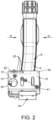
- Figur 2
- eine Vorderansicht des Ausführungsbeispiels der
Figur 1 , - Figur 3
- eine Seitenansicht des Ausführungsbeispiels der
Figur 1 aus der Richtung III derFigur 2 , und - Figur 4
- eine Seitenansicht des Ausführungsbeispiels der
Figur 1 aus der Richtung IV derFigur 2 . - In den
Figuren 1 bis 4 ist nun ein allgemein mit 1 bezeichnetes Ausführungsbeispiel einer Kopplungseinrichtung 1 zusammen mit einem Betätigungsorgan B dargestellt. Im hier gezeigten Ausführungsbeispiel ist das Betätigungsorgan B als ein Pedal P ausgebildet, welches einen Schwenkarm S besitzt, der an seinem oberen Ende eine Öffnung O aufweist, durch welche eine in den Figuren nicht gezeigte Achse hindurchführbar ist, über welche das Pedal P schwenkbar in einem Fahrzeug befestigbar ist. An seinem unteren Ende S" weist der Schwenkarm S ein Betätigungselement E auf, welches im hier gezeigten Fall als eine Pedalplatte ausgeführt ist. Ein derartiges Betätigungsorgan B, insbesondere für ein Fahrzeug, ist bekannt und muss daher nicht mehr näher beschrieben werden. Dem Fachmann ist aus der nachstehenden Beschreibung ersichtlich, dass die hier gezeigte Ausgestaltung des Betätigungsorgans B nur exemplarischen Charakter besitzt. Die beschriebene Kopplungseinrichtung 1 ist nicht auf die Verwendung mit einem derartig ausgebildeten Betätigungsorgan B beschränkt. - Die Kopplungseinrichtung 1 weist einen Grundkörper 10 auf, welcher vorzugsweise plattenförmig ausgestaltet ist. Wie am besten aus den
Figuren 3 und4 ersichtlich ist, ist im oberen Bereich des Grundkörpers 10 ein erstes Kopplungselement 20 und im unteren Bereich ein zweites Kopplungselement 30 angeordnet, deren genaue Ausbildung und Funktion nachstehend noch im Detail beschrieben werden. Unter dem Grundkörper 10 der Kopplungseinrichtung 1 ist ein Anpresselement 40 angeordnet, welches mit dem Grundkörper 10 über ein Spannorgan 41, z. B. eine Spannschraube verbunden ist, so dass durch eine Bewegung des Spannorgans 41 - wie nachstehend beschrieben - der Abstand des Anpresselements 40 zum Grundkörper 10 verändert werden kann. - Das erste Kopplungselement 20 ist hakenförmig ausgebildet und weist einen von einer Rückseite 10" des Grundkörpers 10 abstehenden, in einer ersten Richtung verlaufenden ersten Schenkel 21 und einen sich in einer hierzu quer verlaufenden zweiten Richtung erstreckenden zweiten Schenkel 22 auf, so dass durch diese beiden Schenkel 21 und 22 das hakenartig ausgestaltete erste Kopplungselement 20 ausgebildet ist. Bevorzugt wird, dass der erste Schenkel 21 in einer orthogonalen Richtung zur Rückseite 10" des Grundkörpers 10 und der zweite Schenkel 22 zur ersten Richtung orthogonal verläuft, so dass also die zweite Richtung kollinear zur Rückseite 10" des Grundkörpers 10 ist. Dem Fachmann ist aber ersichtlich, dass die vorstehend beschriebene orthogonale Anordnung der beiden Schenkel 21 und 22 nicht zwingend ist. Vielmehr ist es auch möglich, dass die den Verlauf des ersten Schenkels 21 festlegende erste Richtung schräg zur Rückseite 10" des Grundkörpers 10 verläuft, und/oder dass die den Verlauf des zweiten Schenkels 22 festlegende zweite Richtung nicht kollinear zu der vorgenannten Rückseite 10" ist, sondern geneigt zu dieser verläuft. Wesentlich ist nur, dass bei der Montage der Kopplungseinrichtung 1 auf dem Betätigungsorgan B, hier also auf dem Schwenkarm S des Pedals P, der erste Schenkel 21 seitlich und der zweite Schenkel 22 hinter dem Grundkörper 10 des Betätigungsorgans B, hier also hinter der Rückseite S' des Schwenkarms S verläuft. Durch die vorstehend beschriebene Ausgestaltung wird also - wie aus den Figuren ersichtlich - der Schwenkarm S vom ersten Kopplungselement 20 seitlich und rückseitig zumindest teilweise umschlossen.
- Bevorzugt wird, dass das erste Kopplungselement 20 längenveränderlich ausgebildet ist, so dass der Abstand des vom ersten Schenkel 21 getragenen zweiten Schenkels 22 zur Rückseite 10" des Grundkörpers 10 veränderbar ist.
- Vorzugsweise ist vorgesehen, dass der Grundkörper 10 an seiner Rückseite 10" eine Leiste 24 aufweist, welche sich vorzugsweise über die gesamte Breite des Grundkörpers 10 erstreckt und in welcher erste Schenkel 21 verschiebbar gelagert ist. Die Verwendung der Leiste 24 bewirkt, dass hierdurch der unabgestützte Bereich des ersten Schenkels 21, welcher von der Rückseite 10" des Grundkörpers 10 absteht, verringert werden kann, womit einem Auftreten von unerwünschten Hebelmomenten zumindest entgegengewirkt wird.
- Des Weiteren wird bevorzugt, dass der erste Schenkel 21 des ersten Kopplungselements 20 an mindestens zwei und vorzugsweise mehreren Positionen im Grundkörper 10 montierbar ist. Beim beschriebenen Ausführungsbeispiel wird dies dadurch erreicht, dass die Leiste 24, in welcher der erste Schenkel 21 aufgenommen ist, mehrere voneinander beabstandete Aufnahmeöffnungen 25 für den ersten Schenkel 21 aufweist. Diese Maßnahme besitzt den Vorteil, dass hierdurch in einfacher Art und Weise eine leichte Anpassung der Kopplungseinrichtung 1 an unterschiedlich breite Betätigungsorgane B ermöglicht ist.
- Die Funktionsweise des ersten Kopplungselement 20 sowie der Vorteil der - nicht zwingend erforderlichen - Verlängerbarkeit desselben wird weiter unten noch bei der Beschreibung der Montage der Kopplungseinrichtung 1 am Betätigungsorgan B erläutert werden.
- Das im unteren Bereich des Grundkörpers 10 angeordnete zweite Kopplungselement 30 dient nun dazu, das untere Ende B' des Betätigungsorgans B, hier also das untere Ende S" des Schwenkarms S, zu umfassen. Hierzu ist vorgesehen, dass das zweite Kopplungselement 30 wiederum hakenartig ausgebildet ist und sich - wie aus den Figuren ersichtlich - im montierten Zustand um das untere Ende B' des Betätigungsorgans B herum erstreckt. Hierzu weist das zweite Kopplungselement 30 wiederum einen in einer ersten Richtung verlaufenden ersten Schenkel 31, einen in einer zweiten Richtung verlaufenden zweiten Schenkel 32 und vorzugsweise einen in einer dritten Richtung verlaufenden dritten Schenkel 33 auf. Bevorzugt wird wiederum, dass der dritte Schenkel 33 orthogonal zum zweiten Schenkel 32 verläuft, der wiederum orthogonal zum ersten Schenkel 31 angeordnet ist, obwohl auch hier eine derartige orthogonale Anordnung nicht zwingend ist. Wesentlich ist, dass - analog zum ersten Kopplungselement 20 - der erste Schenkel 31 sich an der Vorderseite 10' des Grundkörpers 10 erstreckt und der zweite Schenkel 32 unter dem unteren Ende B' des Betätigungsorgans B angeordnet ist, also dass hierdurch das untere Ende B' umfasst wird. Das hakenförmig ausgebildete zweite Kopplungselement 30 bildet somit einen unteren Anschlag aus, welcher bewirkt, dass bei einer Beaufschlagung der Kopplungseinrichtung 1 und somit des Betätigungsorgans B durch den Aktuator diese nicht nach oben (in der Darstellung der Figuren) ausweichen kann. Der vom zweiten Schenkel 32 abstehende dritte Schenkel 33 hintergreift hierbei das untere Ende B' des Betätigungsorgans B und beaufschlagt im montierten Zustand dessen Rückseite. Es ist aber durchaus möglich, dass dieser dritte Schenkel 33 nicht vonnöten ist, wenn durch die ersten beiden Schenkel 31 und 32 eine hinreichend sichere Festlegung des zweiten Kopplungselements 30 am Betätigungsorgan B, z. B. durch eine entsprechende Ausgestaltung des zweiten Schenkels 32 mit einer z. B. rutschsicheren Oberfläche, gewährleistet ist, dass im montierten Zustand das zweite Kopplungselement 30 hinreichend betriebssicher am Betätigungsorgan B angebracht werden kann.
- Des Weiteren wird wiederum bevorzugt, dass auch das zweite Kopplungselement 30 - wie auch das erste Kopplungselement 20 - lageveränderlich am Grundkörper 10 angeordnet ist. Insbesondere wird bevorzugt, dass das zweite Kopplungselement 30 in unterschiedlichen Breitenpositionen des Grundkörpers 10 an dessen Schmalseite anordbar ist.
- Vorzugsweise ist wiederum das zweite Kopplungselement 30 längenveränderbar ausgebildet. Hierbei wird bevorzugt, dass der erste Schenkel 31 verschiebbar im Grundkörper 10 angeordnet ist. Auch hier muss wieder betont werden, dass diese Längenveränderbarkeit des zweiten Kopplungselements 30 zwar vorteilhaft, aber aus den nachstehend aufgeführten Gründen nicht zwingend ist.
- Wie vorstehend beschrieben, umgreift das zweite Kopplungselement 30 das untere Ende B` des Betätigungsorgans B und es wird ein unterer Anschlag für die Kopplungseinrichtung 1 ausgebildet, welcher bewirkt, dass bei einer Kraftbeaufschlagung der Kopplungseinrichtung 1 diese nicht nach oben ausweichen kann. Bevorzugt wird, dass die Kopplungseinrichtung 1 einen zum unteren Anschlag komplementären oberen Anschlag aufweist, welcher ein Ausweichen der am Betätigungsorgan B festgelegten Kopplungseinrichtung 1 nach unten zumindest erschwert. Hierzu ist beim beschriebenen Ausführungsbeispiel vorgesehen, dass die Kopplungseinrichtung 1 ein drittes Kopplungselement 45 aufweist, welches den vorstehend angesprochenen oberen Anschlag ausbildet. Beim hier beschriebenen Ausführungsbeispiel ist hierzu vorgesehen, dass am Anpresselement 40 - wie am besten aus den
Figuren 3 und4 ersichtlich ist - ein von der Rückseite 40' des Anpresselements 40 abstehenden Vorsprung 46 angeordnet ist, welcher das obere Ende des Betätigungselements E übergreift, so dass ein Ausweichen der Kopplungseinrichtung 1 - in der Darstellung derFiguren 3 und4 - nach unten erschwert oder verhindert wird. Auch hier kann wieder vorgesehen sein, dass der Vorsprung 46 verschiebbar im Grundkörper 40a des Anpresselements 40 gelagert ist, wie dies z. B. beim ersten Kopplungselement 20 beschrieben wurde. - Des weiteren wird bevorzugt, dass das Anpresselement 40 eine der Leiste 24 des ersten Kopplungselements 20 entsprechende Leiste 47 aufweist, in welcher der Vorsprung 46 - falls gewünscht verschiebbar - angeordnet ist. Auch hier wird durch diese Maßnahme die unabgestützte Länge des Vorsprungs 46, welche auf der Rückseite 40' des Anpresselements 40 hervorsteht, verringert.
- Bevorzugt wird des Weiteren, dass - wie aus den
Figuren 3 und4 ersichtlich - diese Leiste 47 eine abgeschrägte Form aufweist. Dies ist insbesondere dann von Vorteil, wenn - wie beim beschriebenen Ausführungsbeispiel - das Betätigungselement E nicht eben verläuft, insbesondere wie in den Figuren dargestellt, einen gekrümmten Verlauf aufweist, da sich durch diese Maßnahme das Anpresselement 40 besser am Betätigungselement E abstützen kann. - Zur Montage der Kopplungseinrichtung 1 auf dem Betätigungsorgan B wird - bei hinreichend weit herausgezogenen Kopplungselementen 20, 30 - der Grundkörper 10 und somit das mit ihm über das Spannorgan 41 verbundene Anpresselement 40 dem unteren Ende B' des Betätigungsorgans B angenähert und das Anpresselement 40 wird in Anlage zum Betätigungselement E des Betätigungsorgans B gebracht oder zumindest an dieses angenähert. Das dritte Kopplungselement 45 übergreift dabei das obere Ende E' des Betätigungselements E. Falls erforderlich wird der Vorsprung 46 durch eine entsprechende Bewegung lagepositioniert, so dass der vorstehend beschriebene obere Anschlag der Kopplungseinrichtung 1 ausgebildet wird. Dann wird das erste Kopplungselement 20 derart angeordnet, dass der zweite Schenkel 22 hinter dem Betätigungsorgan B liegt und vorzugsweise an dessen Rückseite anliegt, wie in den
Figuren 3 und4 dargestellt. Falls erforderlich wird dazu der erste Schenkel 21 des ersten Kopplungselements 20 eingeschoben. In entsprechender Art und Weise wird das zweite Kopplungselement 30 so angeordnet, dass der dritte Schenkel 33 hinter dem unteren Ende B' des Betätigungsorgans B liegt, wie dies ebenfalls in den Figuren dargestellt ist. Erforderlichenfalls wird dabei der erste Schenkel 31 des zweiten Kopplungselements 30 eingeschoben. Dem Fachmann ist natürlich ersichtlich, dass es nicht zwingend ist, dass das erste Kopplungselement 20 vor dem zweiten Kopplungselement 30 wie vorstehend beschrieben lagepositioniert wird. Natürlich ist es möglich, zuerst das zweite Kopplungselement 30 und dann das erste Kopplungselement 20 zu positionieren, wobei natürlich auch eine gleichzeitige Positionierung dieser beiden Kopplungselemente 20, 30 möglich ist. - Nachdem die Kopplungselemente 20, 30 und 45 lagepositioniert wurden, wird das Spannorgan 41 derart betätigt, dass der Abstand zwischen dem Anpresselement 40 und dem Grundkörper 10 vergrößert wird. Das Anpresselement 40 wird dabei gegen das Betätigungselement E des Betätigungsorgans B gepresst und der Grundkörper 10 und somit die mit ihm verbundenen Kopplungselemente 20, 30 und 45 werden somit in Anlage zum Betätigungsorgan B gebracht und legen somit die Kopplungseinrichtung 1 an diesem formschlüssig fest.
- Dem Fachmann ist ersichtlich, dass der vorstehend beschriebene Montagevorgang nur exemplarischen Charakter besitzt. Vielmehr ist es möglich, in Abhängigkeit von der speziellen Gestaltung und/oder Konfiguration des Betätigungsorgans B von der vorstehend beschriebenen Vorgangsweise abzuweichen.
- An dieser Stelle soll noch erwähnt werden, dass es nicht zwingend ist, das Anpresselement 40 als eine Anpressplatte 40' auszubilden, wie dies in den Figuren dargestellt ist. Es kann für gewisse Anwendungszwecke ausreichend sein, dass auf dieses plattenförmige Anpresselement 40 verzichtet und folglich das Spannorgan 41 direkt am Betätigungsorgan B angreift, damit der Grundkörper 10 von diesem wegbewegt und somit die beiden Kopplungselemente 20, 30 in formschlüssige Anlage an das Betätigungsorgan B gebracht werden können.
- Es ist auch denkbar, dass das Anlegen der Kopplungselemente 20, 30 an das Betätigungsorgan B derart erfolgt, dass der Grundkörper 10 der Kopplungseinrichtung 1 in Anlage mit dem Betätigungsorgan B gebracht und dann die beiden Kopplungselemente 20, 30 durch eine Spanneinrichtung gegen die Rückseite des Betätigungsorgans B gezogen werden. Hierzu kann vorgesehen sein, dass jedes dieser beiden Kopplungselemente 20, 30 ein Spannorgan (nicht gezeigt) aufweist. Auch dann kann das Anpresselement 40 entfallen, da die Rückseite 10" des Grundkörpers 10 auf der Vorderseite des Betätigungsorgans B aufliegt.
- Bei der vorstehenden Beschreibung wurde davon ausgegangen, dass mindestens eines der Kopplungselemente 20, 30 längenverstellbar ausgebildet ist. Eine derartige Ausgestaltung erlaubt in vorteilhafter Art und Weise eine einfachere Montage und Festlegung der Kopplungseinrichtung 1 am Betätigungsorgan B. Die Verstellbarkeit der Kopplungselemente 20, 30 erlaubt in vorteilhafter Art und Weise auch eine einfache Anpassbarkeit der beschriebenen Kopplungseinrichtung 1 an unterschiedlich konfigurierte Betätigungsorgane B, da hierdurch der Abstand des zweiten Schenkels 22 bzw. 32 des ersten und/oder zweiten Kopplungselements 20 und/oder 30 individuell auf das jeweilige Betätigungsorgan B angepasst werden kann. Eine derartige Verstellbarkeit ist aber nicht zwingend. Wenn auf die vorstehend beschriebene individuelle Anpassbarkeit verzichtet werden kann oder soll, ist es ausreichend, dass eines oder beide Kopplungselemente 20 und/oder 30 eine feste Länge besitzen, also nicht beweglich in dem Grundkörper 10 angeordnet sind.
- Nachdem die Kopplungseinrichtung 1 wie vorstehend beschrieben am Betätigungsorgan B festgelegt wurde, kann nun ein in den Figuren nicht gezeigter Aktuator, insbesondere ein Aktuator eines Fahrroboters, mit dem Grundkörper 10 verbunden werden, so dass durch die Bewegung des Aktuators eine Betätigungsbewegung des Betätigungsorgans B bewirkt wird. Hierzu ist vorgesehen, dass an der Vorderseite 10' des Grundkörpers 10 der Kopplungseinrichtung 1 ein entsprechendes Verbindungselement 50 vorgesehen ist, welches eine Verbindung der Kopplungseinrichtung 1 mit dem Aktuator ermöglicht. Im hier beschriebenen Fall ist vorgesehen, dass in der Vorderseite 10' des Grundkörpers 10 eine Gewindebohrung 51 vorgesehen ist, in welche eine Ende des Aktuators, insbesondere das vordere Ende einer Aktuatorstange, einschraubbar ist. Natürlich ist diese Art und Weise der Verbindung zwischen Aktuator und Kopplungseinrichtung 1 nicht zwingend. Vielmehr ist eine Vielzahl von Möglichkeiten denkbar, den Aktuator und die Kopplungseinrichtung 1 miteinander zu verbinden.
- Vorzugsweise ist vorgesehen, dass - wie insbesondere aus der
Figur 2 ersichtlich ist - das Verbindungselement 50 zur Mitte des Grundkörpers 10 hin versetzt angeordnet ist. Eine derartige Maßnahme besitzt den Vorteil, dass hierdurch der Grundkörper 10 nicht nur vom Aktuator kraftbeaufschlagbar ist, sondern dass auch Platz für den Fuß eines Bedieners verbleibt, so dass das Betätigungsorgan B auch vom Bediener beaufschlagbar ist. Dies ist insbesondere dann von Vorteil, wenn durch den Aktuator und die Kopplungseinrichtung 1 ein Bremspedal bedient werden soll, da aufgrund der vorstehend beschriebenen versetzten Anordnung des Verbindungselements 50 noch eine "manuelle" Notbremsfunktion durchgeführt werden kann. - Zusammenfassend ist festzuhalten, dass durch die beschriebenen Maßnahmen in vorteilhafter Art und Weise eine Kopplungseinrichtung 1 für ein Betätigungsorgan B, insbesondere für ein Betätigungsorgans B eines Fahrzeugs, ausgebildet wird, welches sich dadurch auszeichnet, dass die Kopplungseinrichtung 1 formschlüssig am Betätigungsorgan B festgelegt werden kann. Die beschriebene Kopplungseinrichtung 1 zeichnet sich durch ihren einfachen Aufbau und ihre leichte Montierbarkeit aus. Von Vorteil ist, dass durch eine Längenverstellbarkeit des ersten Schenkels 21 des ersten Kopplungselements 20 und/oder des ersten Schenkels 31 des zweiten Kopplungselements 30 und/oder des Vorsprungs 46 des dritten Kopplungselements 45 nicht nur eine einfachere Montage, sondern auch eine Anpassung an unterschiedlich konfigurierte Betätigungsorgane ermöglicht ist.
- Bei der vorstehenden Beschreibung wird davon ausgegangen, dass das Betätigungsorgan B hängend angeordnet ist, dass also die durch die Öffnung O verlaufende Schwenkachse über dem Betätigungselement E verläuft. Die beschriebene Kopplungseinrichtung 1 ist natürlich nicht auf eine derartige Anordnung des Betätigungsorgans B beschränkt. Vielmehr ist es z. B. auch möglich, die Kopplungseinrichtung 1 bei einem stehend angeordneten Betätigungsorgan B einzusetzen, also bei einem Betätigungsorgan B, bei dem die vorgenannte Schwenkachse unter dem Betätigungselement E verläuft. Bei einer derartigen Anordnung wird dann bevorzugt, dass die Kopplungseinrichtung 1 gegenüber der in den
Figuren 1 bis 4 dargestellten Anordnung um 180° gedreht angeordnet ist, so dass also das zweite Kopplungselement 30 über dem - dann oberen Ende B" - des Betätigungsorgans B angeordnet ist. Auch ist es nicht erforderlich, dass das Betätigungsorgan B als ein Schwenk-Betätigungsorgan B mit einem Schwenkarm S ausgebildet ist. Die beschriebene Kopplungseinrichtung 1 eignet sich auch für einen Einsatz - ohne ein weiteres Beispiel zu nennen - bei Betätigungsorgan B, die durch eine lineare Betätigungsbewegung, z. B. eine Verschiebebewegung, betätigbar sind.
Claims (13)
- Kopplungseinrichtung zur Befestigung eines Aktuators an einem Betätigungsorgan (B), insbesondere einem Pedal (P) eines Fahrzeugs, wobei die Kopplungseinrichtung (1) mit dem Aktuator verbindbar und in Eingriff mit dem Betätigungsorgan (B) bringbar ist, wobei die Kopplungseinrichtung (1) einen Grundkörper (10) aufweist, an dem ein hakenförmiges erstes Kopplungselement (20) angeordnet ist, wobei das erste Kopplungselement (20) einen von einer Rückseite (10") des Grundkörpers (10) abstehenden ersten Schenkel (21) und einen hierzu quer verlaufenden zweiten Schenkel (22) aufweist, dadurch gekennzeichnet, dass der erste Schenkel (21) im montierten Zustand der Kopplungseinrichtung (1) seitlich zum Betätigungsorgan (B) und der zweite Schenkel (22) hinter dem Betätigungsorgan (B) angeordnet ist, dass der Grundkörper (10) mindestens ein hakenförmiges zweites Kopplungselement (20) aufweist, dass das mindestens eine zweite Kopplungselement (30) einen von einer Seite des Grundkörpers (10) abstehenden ersten Schenkel (31) und einen hierzu quer verlaufenden zweiten Schenkel (32) aufweist, wobei im montierten Zustand der erste Schenkel (31) an der Vorderseite des Betätigungsorgans (B) und der zweite Schenkel (32) des zweiten Kopplungselements (30) quer zu diesem ersten Schenkel (31) und unter dem unteren Ende (B') des Betätigungsorgans (B) verläuft, so dass das erste hakenförmige Kopplungselement (20) und das zweite hakenförmige Kopplungselement (30) das Betätigungsorgan (B) formschlüssig umgreifen.
- Kopplungseinrichtung nach Anspruch 1, dadurch gekennzeichnet, dass das zweite Kopplungselement (30) einen vom zweiten Schenkel (32) abstehenden dritten Schenkel (33) aufweist, und dass im montierten Zustand der dritte Schenkel (33) hinter einem unteren Ende (B') des Betätigungsorgans (B) verläuft.
- Kopplungseinrichtung nach einem der Ansprüche 1 oder 2, dadurch gekennzeichnet, dass die Kopplungseinrichtung (1) ein drittes Kopplungselement (45) besitzt, welches ein Ende (E') eines Betätigungselements (E) des Betätigungsorgans (B) zumindest teilweise umfasst.
- Kopplungseinrichtung nach einem der Ansprüche 1 bis 3, dadurch gekennzeichnet, dass die Kopplungseinrichtung (1) ein Anpresselement (40) mit einem Grundkörper (40a) aufweist, durch welches der Abstand des Grundkörpers (10) zu dem Betätigungselement (E) des Betätigungsorgans (B) veränderbar ist.
- Kopplungseinrichtung nach Anspruch 4, dadurch gekennzeichnet, dass das Anpresselement (40) ein Spannorgan (41) aufweist, durch welches das Betätigungsorgan (B) beaufschlagbar ist.
- Kopplungseinrichtung nach einem der Ansprüche 4 oder 5, dadurch gekennzeichnet, dass das Anpresselement (40) eine Anpressplatte (40') aufweist, welche auf das Betätigungsorgan (B) aufsetzbar ist.
- Kopplungseinrichtung nach einem der Ansprüche 3 bis 6, dadurch gekennzeichnet, dass das dritte Kopplungselement (45) am Grundkörper (40a) des Anpresselements (40) angeordnet ist.
- Kopplungseinrichtung nach einem der Ansprüche 1 bis 7, dadurch gekennzeichnet, dass der erste Schenkel (21) des ersten Kopplungselements (20) und/oder der erste Schenkel (31) des zweiten Kopplungselements (30) längenveränderbar ausgebildet ist oder sind.
- Kopplungseinrichtung nach einem der Ansprüche 3 bis 8, dadurch gekennzeichnet, dass der Vorsprung (46) des dritten Kopplungselements (45) längenveränderbar ausgebildet ist.
- Kopplungseinrichtung nach einem der Ansprüche 3 bis 9, dadurch gekennzeichnet, dass der Vorsprung (46) des dritten Kopplungselements (45) längenveränderbar im Grundkörper (40a) des Anpresselements (40) angeordnet ist.
- Kopplungseinrichtung nach einem der vorangehenden Ansprüche, dadurch gekennzeichnet, dass das erste Kopplungselement (20) und/oder das zweite Kopplungselement (30) lageveränderlich am Grundkörper (10) der Kopplungseinrichtung (1) angeordnet oder anordbar ist.
- Kopplungseinrichtung nach einem der vorangehenden Ansprüche, dadurch gekennzeichnet, dass an der Vorderseite (10') des Grundkörpers (10) ein Verbindungselement (50) vorgesehen ist, mittels dessen der Aktuator an der Kopplungseinrichtung (1) festlegbar ist.
- Kopplungseinrichtung nach Anspruch 12, dadurch gekennzeichnet, dass das Verbindungselement (50) dezentral im oder am Grundkörper (10) angeordnet ist.
Applications Claiming Priority (3)
| Application Number | Priority Date | Filing Date | Title |
|---|---|---|---|
| DE102020004636.3A DE102020004636A1 (de) | 2020-07-30 | 2020-07-30 | Kopplungseinrichtung zur Befestigung eines Aktuators an einem Betätigungsorgan |
| DE202020003278.6U DE202020003278U1 (de) | 2020-07-30 | 2020-07-30 | Kopplungseinrichtung zur Befestigung eines Aktuators an einem Betätigungsorgan |
| PCT/EP2021/025269 WO2022022852A1 (de) | 2020-07-30 | 2021-07-21 | Kopplungseinrichtung zur befestigung eines aktuators an einem betätigungsorgan |
Publications (2)
| Publication Number | Publication Date |
|---|---|
| EP4188764A1 EP4188764A1 (de) | 2023-06-07 |
| EP4188764B1 true EP4188764B1 (de) | 2024-08-21 |
Family
ID=77265047
Family Applications (1)
| Application Number | Title | Priority Date | Filing Date |
|---|---|---|---|
| EP21751975.0A Active EP4188764B1 (de) | 2020-07-30 | 2021-07-21 | Kopplungseinrichtung zur befestigung eines aktuators an einem betätigungsorgan |
Country Status (6)
| Country | Link |
|---|---|
| US (1) | US12455588B2 (de) |
| EP (1) | EP4188764B1 (de) |
| JP (1) | JP2023536149A (de) |
| KR (1) | KR102834411B1 (de) |
| ES (1) | ES2994508T3 (de) |
| WO (1) | WO2022022852A1 (de) |
Family Cites Families (12)
| Publication number | Priority date | Publication date | Assignee | Title |
|---|---|---|---|---|
| US1128975A (en) * | 1914-03-10 | 1915-02-16 | Fred Harrington | Extension pedal attachment. |
| US1346361A (en) * | 1917-12-17 | 1920-07-13 | Williams Frank Lester | Pedal extension |
| US1480211A (en) * | 1921-10-28 | 1924-01-08 | James A Kauffman | Pedal attachment |
| DE2004979B2 (de) | 1970-02-04 | 1974-04-18 | Dr.-Ing.H.C. F. Porsche Ag, 7000 Stuttgart | Einrichtung zum selbsttätigen Betätigen der Bedienungseinrichtungen von Fahrzeugen, insbesondere Kraftfahrzeugen |
| US3662593A (en) | 1970-11-23 | 1972-05-16 | Gen Motors Corp | Test apparatus for depressing vehicle brake and accelerator pedals |
| AU2250388A (en) | 1987-07-22 | 1989-02-13 | Autolux, Inc. | Apparatus for remotely controlling a brake or accelerator pedal on a vehicle |
| US5497678A (en) * | 1994-08-09 | 1996-03-12 | Chou; Wayne W. | Adjustable adaptor attachment for the accelerator pedal of a manual transmission vehicle used in competitive driving |
| US6634466B1 (en) * | 2001-12-12 | 2003-10-21 | Master Concepts, Inc. | Brake pedal fastener |
| US8615334B2 (en) | 2007-05-18 | 2013-12-24 | Terry Ewert | Remote control kit system for full-sized vehicle |
| US7730806B1 (en) * | 2007-10-29 | 2010-06-08 | Stanzie Grimaldi | Vehicle pedal booster and associated method |
| KR101283357B1 (ko) | 2012-03-19 | 2013-07-08 | 교통안전공단 | 자동차 성능시험용 가속페달 제어장치 |
| US10857990B2 (en) * | 2018-11-20 | 2020-12-08 | Robert Whitt | Hydraulic system bleed device and system thereof |
-
2021
- 2021-07-21 EP EP21751975.0A patent/EP4188764B1/de active Active
- 2021-07-21 JP JP2023506156A patent/JP2023536149A/ja active Pending
- 2021-07-21 ES ES21751975T patent/ES2994508T3/es active Active
- 2021-07-21 KR KR1020237006499A patent/KR102834411B1/ko active Active
- 2021-07-21 WO PCT/EP2021/025269 patent/WO2022022852A1/de not_active Ceased
-
2023
- 2023-01-29 US US18/161,073 patent/US12455588B2/en active Active
Also Published As
| Publication number | Publication date |
|---|---|
| KR102834411B1 (ko) | 2025-07-14 |
| US20230176605A1 (en) | 2023-06-08 |
| KR20230043944A (ko) | 2023-03-31 |
| EP4188764A1 (de) | 2023-06-07 |
| US12455588B2 (en) | 2025-10-28 |
| ES2994508T3 (en) | 2025-01-24 |
| JP2023536149A (ja) | 2023-08-23 |
| WO2022022852A1 (de) | 2022-02-03 |
Similar Documents
| Publication | Publication Date | Title |
|---|---|---|
| EP2200134B1 (de) | Baugruppe mit Gehäuse für Profilschiene | |
| AT518248B1 (de) | Möbelbeschlag | |
| EP1976735B1 (de) | Scheibenwischvorrichtung, insbesondere für ein kraftfahrzeug | |
| EP1852643A2 (de) | Schelle zum Befestigen eines rohr- oder schlauchförmigen Gegenstandes | |
| EP2365783A2 (de) | Klemmhalterung | |
| EP1544379B1 (de) | Klemmvorrichtung | |
| WO2018033221A1 (de) | Möbelscharnier | |
| EP1394012A1 (de) | Verriegelungsvorrichtung für zwei relativ zueinander verschiebbar gelagerte Bauteile | |
| EP2783437B1 (de) | Montageschiene für den innenausbau eines schaltschrankgehäuses | |
| EP2852363A1 (de) | Befestigungseinrichtung zum befestigen von zubehörteilen an medizinischen einrichtungen | |
| EP2855194B1 (de) | Betätigungseinheit für einen fahrzeugsitz | |
| EP2514053A1 (de) | Vorrichtung zum befestigen einer moduleinheit auf einer tragschiene | |
| EP4188764B1 (de) | Kopplungseinrichtung zur befestigung eines aktuators an einem betätigungsorgan | |
| EP2783919B1 (de) | Vorrichtung zum Befestigen einer Dachbox | |
| DE202020003278U1 (de) | Kopplungseinrichtung zur Befestigung eines Aktuators an einem Betätigungsorgan | |
| DE102020004636A1 (de) | Kopplungseinrichtung zur Befestigung eines Aktuators an einem Betätigungsorgan | |
| DE202004017022U1 (de) | Vorrichtung zum Verbinden zweier Montageprofile sowie Baugruppe mit einer derartigen Vorrichtung | |
| EP2565354A2 (de) | Schloss für die Motorhauben von Kraftfahrzeugen, insbesondere von Lastkraftwagen | |
| DE202007000779U1 (de) | Schnellspannhalter für elektronische oder opto-elektronische Geräte | |
| DE10341117B4 (de) | Verbindungselement zur Verbindung von Trennwandabschnitten | |
| EP1966012A1 (de) | Befestigungsvorrichtung | |
| AT413118B (de) | Einrichtung zur befestigung eines zusatzgerätes, insbesondere eines ladegerätes, an einem tragfahrzeug | |
| DE19828233A1 (de) | Wandkonsole | |
| DE19728702C1 (de) | Halterung | |
| DE102016205861A1 (de) | Befestigungseinrichtung zum Befestigen eines Zubehörteils an einer Halteeinrichtung einer medizinischen Einrichtung und ein Verfahren dazu |
Legal Events
| Date | Code | Title | Description |
|---|---|---|---|
| STAA | Information on the status of an ep patent application or granted ep patent |
Free format text: STATUS: UNKNOWN |
|
| STAA | Information on the status of an ep patent application or granted ep patent |
Free format text: STATUS: THE INTERNATIONAL PUBLICATION HAS BEEN MADE |
|
| PUAI | Public reference made under article 153(3) epc to a published international application that has entered the european phase |
Free format text: ORIGINAL CODE: 0009012 |
|
| STAA | Information on the status of an ep patent application or granted ep patent |
Free format text: STATUS: REQUEST FOR EXAMINATION WAS MADE |
|
| 17P | Request for examination filed |
Effective date: 20230228 |
|
| AK | Designated contracting states |
Kind code of ref document: A1 Designated state(s): AL AT BE BG CH CY CZ DE DK EE ES FI FR GB GR HR HU IE IS IT LI LT LU LV MC MK MT NL NO PL PT RO RS SE SI SK SM TR |
|
| DAV | Request for validation of the european patent (deleted) | ||
| DAX | Request for extension of the european patent (deleted) | ||
| GRAP | Despatch of communication of intention to grant a patent |
Free format text: ORIGINAL CODE: EPIDOSNIGR1 |
|
| STAA | Information on the status of an ep patent application or granted ep patent |
Free format text: STATUS: GRANT OF PATENT IS INTENDED |
|
| INTG | Intention to grant announced |
Effective date: 20240216 |
|
| GRAJ | Information related to disapproval of communication of intention to grant by the applicant or resumption of examination proceedings by the epo deleted |
Free format text: ORIGINAL CODE: EPIDOSDIGR1 |
|
| STAA | Information on the status of an ep patent application or granted ep patent |
Free format text: STATUS: REQUEST FOR EXAMINATION WAS MADE |
|
| GRAP | Despatch of communication of intention to grant a patent |
Free format text: ORIGINAL CODE: EPIDOSNIGR1 |
|
| STAA | Information on the status of an ep patent application or granted ep patent |
Free format text: STATUS: GRANT OF PATENT IS INTENDED |
|
| INTC | Intention to grant announced (deleted) | ||
| INTG | Intention to grant announced |
Effective date: 20240507 |
|
| GRAS | Grant fee paid |
Free format text: ORIGINAL CODE: EPIDOSNIGR3 |
|
| GRAA | (expected) grant |
Free format text: ORIGINAL CODE: 0009210 |
|
| STAA | Information on the status of an ep patent application or granted ep patent |
Free format text: STATUS: THE PATENT HAS BEEN GRANTED |
|
| AK | Designated contracting states |
Kind code of ref document: B1 Designated state(s): AL AT BE BG CH CY CZ DE DK EE ES FI FR GB GR HR HU IE IS IT LI LT LU LV MC MK MT NL NO PL PT RO RS SE SI SK SM TR |
|
| REG | Reference to a national code |
Ref country code: GB Ref legal event code: FG4D Free format text: NOT ENGLISH |
|
| REG | Reference to a national code |
Ref country code: CH Ref legal event code: EP |
|
| REG | Reference to a national code |
Ref country code: DE Ref legal event code: R096 Ref document number: 502021004880 Country of ref document: DE |
|
| REG | Reference to a national code |
Ref country code: IE Ref legal event code: FG4D Free format text: LANGUAGE OF EP DOCUMENT: GERMAN |
|
| P01 | Opt-out of the competence of the unified patent court (upc) registered |
Free format text: CASE NUMBER: APP_53292/2024 Effective date: 20241001 |
|
| REG | Reference to a national code |
Ref country code: SE Ref legal event code: TRGR |
|
| REG | Reference to a national code |
Ref country code: LT Ref legal event code: MG9D |
|
| REG | Reference to a national code |
Ref country code: NL Ref legal event code: MP Effective date: 20240821 |
|
| PG25 | Lapsed in a contracting state [announced via postgrant information from national office to epo] |
Ref country code: NO Free format text: LAPSE BECAUSE OF FAILURE TO SUBMIT A TRANSLATION OF THE DESCRIPTION OR TO PAY THE FEE WITHIN THE PRESCRIBED TIME-LIMIT Effective date: 20241121 |
|
| PG25 | Lapsed in a contracting state [announced via postgrant information from national office to epo] |
Ref country code: NL Free format text: LAPSE BECAUSE OF FAILURE TO SUBMIT A TRANSLATION OF THE DESCRIPTION OR TO PAY THE FEE WITHIN THE PRESCRIBED TIME-LIMIT Effective date: 20240821 Ref country code: FI Free format text: LAPSE BECAUSE OF FAILURE TO SUBMIT A TRANSLATION OF THE DESCRIPTION OR TO PAY THE FEE WITHIN THE PRESCRIBED TIME-LIMIT Effective date: 20240821 Ref country code: GR Free format text: LAPSE BECAUSE OF FAILURE TO SUBMIT A TRANSLATION OF THE DESCRIPTION OR TO PAY THE FEE WITHIN THE PRESCRIBED TIME-LIMIT Effective date: 20241122 Ref country code: PT Free format text: LAPSE BECAUSE OF FAILURE TO SUBMIT A TRANSLATION OF THE DESCRIPTION OR TO PAY THE FEE WITHIN THE PRESCRIBED TIME-LIMIT Effective date: 20241223 Ref country code: PL Free format text: LAPSE BECAUSE OF FAILURE TO SUBMIT A TRANSLATION OF THE DESCRIPTION OR TO PAY THE FEE WITHIN THE PRESCRIBED TIME-LIMIT Effective date: 20240821 |
|
| PG25 | Lapsed in a contracting state [announced via postgrant information from national office to epo] |
Ref country code: BG Free format text: LAPSE BECAUSE OF FAILURE TO SUBMIT A TRANSLATION OF THE DESCRIPTION OR TO PAY THE FEE WITHIN THE PRESCRIBED TIME-LIMIT Effective date: 20240821 |
|
| PG25 | Lapsed in a contracting state [announced via postgrant information from national office to epo] |
Ref country code: LV Free format text: LAPSE BECAUSE OF FAILURE TO SUBMIT A TRANSLATION OF THE DESCRIPTION OR TO PAY THE FEE WITHIN THE PRESCRIBED TIME-LIMIT Effective date: 20240821 |
|
| PG25 | Lapsed in a contracting state [announced via postgrant information from national office to epo] |
Ref country code: IS Free format text: LAPSE BECAUSE OF FAILURE TO SUBMIT A TRANSLATION OF THE DESCRIPTION OR TO PAY THE FEE WITHIN THE PRESCRIBED TIME-LIMIT Effective date: 20241221 |
|
| PG25 | Lapsed in a contracting state [announced via postgrant information from national office to epo] |
Ref country code: HR Free format text: LAPSE BECAUSE OF FAILURE TO SUBMIT A TRANSLATION OF THE DESCRIPTION OR TO PAY THE FEE WITHIN THE PRESCRIBED TIME-LIMIT Effective date: 20240821 |
|
| REG | Reference to a national code |
Ref country code: ES Ref legal event code: FG2A Ref document number: 2994508 Country of ref document: ES Kind code of ref document: T3 Effective date: 20250124 |
|
| PG25 | Lapsed in a contracting state [announced via postgrant information from national office to epo] |
Ref country code: RS Free format text: LAPSE BECAUSE OF FAILURE TO SUBMIT A TRANSLATION OF THE DESCRIPTION OR TO PAY THE FEE WITHIN THE PRESCRIBED TIME-LIMIT Effective date: 20241121 |
|
| PG25 | Lapsed in a contracting state [announced via postgrant information from national office to epo] |
Ref country code: RS Free format text: LAPSE BECAUSE OF FAILURE TO SUBMIT A TRANSLATION OF THE DESCRIPTION OR TO PAY THE FEE WITHIN THE PRESCRIBED TIME-LIMIT Effective date: 20241121 Ref country code: PT Free format text: LAPSE BECAUSE OF FAILURE TO SUBMIT A TRANSLATION OF THE DESCRIPTION OR TO PAY THE FEE WITHIN THE PRESCRIBED TIME-LIMIT Effective date: 20241223 Ref country code: PL Free format text: LAPSE BECAUSE OF FAILURE TO SUBMIT A TRANSLATION OF THE DESCRIPTION OR TO PAY THE FEE WITHIN THE PRESCRIBED TIME-LIMIT Effective date: 20240821 Ref country code: NO Free format text: LAPSE BECAUSE OF FAILURE TO SUBMIT A TRANSLATION OF THE DESCRIPTION OR TO PAY THE FEE WITHIN THE PRESCRIBED TIME-LIMIT Effective date: 20241121 Ref country code: NL Free format text: LAPSE BECAUSE OF FAILURE TO SUBMIT A TRANSLATION OF THE DESCRIPTION OR TO PAY THE FEE WITHIN THE PRESCRIBED TIME-LIMIT Effective date: 20240821 Ref country code: LV Free format text: LAPSE BECAUSE OF FAILURE TO SUBMIT A TRANSLATION OF THE DESCRIPTION OR TO PAY THE FEE WITHIN THE PRESCRIBED TIME-LIMIT Effective date: 20240821 Ref country code: IS Free format text: LAPSE BECAUSE OF FAILURE TO SUBMIT A TRANSLATION OF THE DESCRIPTION OR TO PAY THE FEE WITHIN THE PRESCRIBED TIME-LIMIT Effective date: 20241221 Ref country code: HR Free format text: LAPSE BECAUSE OF FAILURE TO SUBMIT A TRANSLATION OF THE DESCRIPTION OR TO PAY THE FEE WITHIN THE PRESCRIBED TIME-LIMIT Effective date: 20240821 Ref country code: GR Free format text: LAPSE BECAUSE OF FAILURE TO SUBMIT A TRANSLATION OF THE DESCRIPTION OR TO PAY THE FEE WITHIN THE PRESCRIBED TIME-LIMIT Effective date: 20241122 Ref country code: FI Free format text: LAPSE BECAUSE OF FAILURE TO SUBMIT A TRANSLATION OF THE DESCRIPTION OR TO PAY THE FEE WITHIN THE PRESCRIBED TIME-LIMIT Effective date: 20240821 Ref country code: BG Free format text: LAPSE BECAUSE OF FAILURE TO SUBMIT A TRANSLATION OF THE DESCRIPTION OR TO PAY THE FEE WITHIN THE PRESCRIBED TIME-LIMIT Effective date: 20240821 |
|
| PG25 | Lapsed in a contracting state [announced via postgrant information from national office to epo] |
Ref country code: RO Free format text: LAPSE BECAUSE OF FAILURE TO SUBMIT A TRANSLATION OF THE DESCRIPTION OR TO PAY THE FEE WITHIN THE PRESCRIBED TIME-LIMIT Effective date: 20240821 Ref country code: SM Free format text: LAPSE BECAUSE OF FAILURE TO SUBMIT A TRANSLATION OF THE DESCRIPTION OR TO PAY THE FEE WITHIN THE PRESCRIBED TIME-LIMIT Effective date: 20240821 Ref country code: DK Free format text: LAPSE BECAUSE OF FAILURE TO SUBMIT A TRANSLATION OF THE DESCRIPTION OR TO PAY THE FEE WITHIN THE PRESCRIBED TIME-LIMIT Effective date: 20240821 |
|
| PG25 | Lapsed in a contracting state [announced via postgrant information from national office to epo] |
Ref country code: EE Free format text: LAPSE BECAUSE OF FAILURE TO SUBMIT A TRANSLATION OF THE DESCRIPTION OR TO PAY THE FEE WITHIN THE PRESCRIBED TIME-LIMIT Effective date: 20240821 |
|
| PG25 | Lapsed in a contracting state [announced via postgrant information from national office to epo] |
Ref country code: CZ Free format text: LAPSE BECAUSE OF FAILURE TO SUBMIT A TRANSLATION OF THE DESCRIPTION OR TO PAY THE FEE WITHIN THE PRESCRIBED TIME-LIMIT Effective date: 20240821 |
|
| PG25 | Lapsed in a contracting state [announced via postgrant information from national office to epo] |
Ref country code: SK Free format text: LAPSE BECAUSE OF FAILURE TO SUBMIT A TRANSLATION OF THE DESCRIPTION OR TO PAY THE FEE WITHIN THE PRESCRIBED TIME-LIMIT Effective date: 20240821 |
|
| REG | Reference to a national code |
Ref country code: DE Ref legal event code: R097 Ref document number: 502021004880 Country of ref document: DE |
|
| PLBE | No opposition filed within time limit |
Free format text: ORIGINAL CODE: 0009261 |
|
| STAA | Information on the status of an ep patent application or granted ep patent |
Free format text: STATUS: NO OPPOSITION FILED WITHIN TIME LIMIT |
|
| PGFP | Annual fee paid to national office [announced via postgrant information from national office to epo] |
Ref country code: GB Payment date: 20250606 Year of fee payment: 5 |
|
| 26N | No opposition filed |
Effective date: 20250522 |
|
| PGFP | Annual fee paid to national office [announced via postgrant information from national office to epo] |
Ref country code: SE Payment date: 20250606 Year of fee payment: 5 |
|
| PGFP | Annual fee paid to national office [announced via postgrant information from national office to epo] |
Ref country code: ES Payment date: 20250819 Year of fee payment: 5 |
|
| PGFP | Annual fee paid to national office [announced via postgrant information from national office to epo] |
Ref country code: DE Payment date: 20250606 Year of fee payment: 5 |
|
| PGFP | Annual fee paid to national office [announced via postgrant information from national office to epo] |
Ref country code: IT Payment date: 20250731 Year of fee payment: 5 |
|
| PGFP | Annual fee paid to national office [announced via postgrant information from national office to epo] |
Ref country code: AT Payment date: 20251020 Year of fee payment: 5 Ref country code: FR Payment date: 20250723 Year of fee payment: 5 |