EP4188710B1 - Beabstandungsvorrichtung für ein system zum laminieren - Google Patents
Beabstandungsvorrichtung für ein system zum laminieren Download PDFInfo
- Publication number
- EP4188710B1 EP4188710B1 EP21749590.2A EP21749590A EP4188710B1 EP 4188710 B1 EP4188710 B1 EP 4188710B1 EP 21749590 A EP21749590 A EP 21749590A EP 4188710 B1 EP4188710 B1 EP 4188710B1
- Authority
- EP
- European Patent Office
- Prior art keywords
- laminate
- membrane
- spacing
- lamination
- designed
- Prior art date
- Legal status (The legal status is an assumption and is not a legal conclusion. Google has not performed a legal analysis and makes no representation as to the accuracy of the status listed.)
- Active
Links
Images


Classifications
-
- B—PERFORMING OPERATIONS; TRANSPORTING
- B32—LAYERED PRODUCTS
- B32B—LAYERED PRODUCTS, i.e. PRODUCTS BUILT-UP OF STRATA OF FLAT OR NON-FLAT, e.g. CELLULAR OR HONEYCOMB, FORM
- B32B37/00—Methods or apparatus for laminating, e.g. by curing or by ultrasonic bonding
- B32B37/0007—Methods or apparatus for laminating, e.g. by curing or by ultrasonic bonding involving treatment or provisions in order to avoid deformation or air inclusion, e.g. to improve surface quality
-
- B—PERFORMING OPERATIONS; TRANSPORTING
- B30—PRESSES
- B30B—PRESSES IN GENERAL
- B30B5/00—Presses characterised by the use of pressing means other than those mentioned in the preceding groups
- B30B5/02—Presses characterised by the use of pressing means other than those mentioned in the preceding groups wherein the pressing means is in the form of a flexible element, e.g. diaphragm, urged by fluid pressure
-
- B—PERFORMING OPERATIONS; TRANSPORTING
- B30—PRESSES
- B30B—PRESSES IN GENERAL
- B30B5/00—Presses characterised by the use of pressing means other than those mentioned in the preceding groups
- B30B5/04—Presses characterised by the use of pressing means other than those mentioned in the preceding groups wherein the pressing means is in the form of an endless band
-
- B—PERFORMING OPERATIONS; TRANSPORTING
- B32—LAYERED PRODUCTS
- B32B—LAYERED PRODUCTS, i.e. PRODUCTS BUILT-UP OF STRATA OF FLAT OR NON-FLAT, e.g. CELLULAR OR HONEYCOMB, FORM
- B32B17/00—Layered products essentially comprising sheet glass, or glass, slag, or like fibres
- B32B17/06—Layered products essentially comprising sheet glass, or glass, slag, or like fibres comprising glass as the main or only constituent of a layer, next to another layer of a specific material
- B32B17/10—Layered products essentially comprising sheet glass, or glass, slag, or like fibres comprising glass as the main or only constituent of a layer, next to another layer of a specific material of synthetic resin
- B32B17/10005—Layered products essentially comprising sheet glass, or glass, slag, or like fibres comprising glass as the main or only constituent of a layer, next to another layer of a specific material of synthetic resin laminated safety glass or glazing
- B32B17/10009—Layered products essentially comprising sheet glass, or glass, slag, or like fibres comprising glass as the main or only constituent of a layer, next to another layer of a specific material of synthetic resin laminated safety glass or glazing characterized by the number, the constitution or treatment of glass sheets
- B32B17/10036—Layered products essentially comprising sheet glass, or glass, slag, or like fibres comprising glass as the main or only constituent of a layer, next to another layer of a specific material of synthetic resin laminated safety glass or glazing characterized by the number, the constitution or treatment of glass sheets comprising two outer glass sheets
-
- B—PERFORMING OPERATIONS; TRANSPORTING
- B32—LAYERED PRODUCTS
- B32B—LAYERED PRODUCTS, i.e. PRODUCTS BUILT-UP OF STRATA OF FLAT OR NON-FLAT, e.g. CELLULAR OR HONEYCOMB, FORM
- B32B17/00—Layered products essentially comprising sheet glass, or glass, slag, or like fibres
- B32B17/06—Layered products essentially comprising sheet glass, or glass, slag, or like fibres comprising glass as the main or only constituent of a layer, next to another layer of a specific material
- B32B17/10—Layered products essentially comprising sheet glass, or glass, slag, or like fibres comprising glass as the main or only constituent of a layer, next to another layer of a specific material of synthetic resin
- B32B17/10005—Layered products essentially comprising sheet glass, or glass, slag, or like fibres comprising glass as the main or only constituent of a layer, next to another layer of a specific material of synthetic resin laminated safety glass or glazing
- B32B17/1055—Layered products essentially comprising sheet glass, or glass, slag, or like fibres comprising glass as the main or only constituent of a layer, next to another layer of a specific material of synthetic resin laminated safety glass or glazing characterized by the resin layer, i.e. interlayer
- B32B17/10788—Layered products essentially comprising sheet glass, or glass, slag, or like fibres comprising glass as the main or only constituent of a layer, next to another layer of a specific material of synthetic resin laminated safety glass or glazing characterized by the resin layer, i.e. interlayer containing ethylene vinylacetate
-
- B—PERFORMING OPERATIONS; TRANSPORTING
- B32—LAYERED PRODUCTS
- B32B—LAYERED PRODUCTS, i.e. PRODUCTS BUILT-UP OF STRATA OF FLAT OR NON-FLAT, e.g. CELLULAR OR HONEYCOMB, FORM
- B32B17/00—Layered products essentially comprising sheet glass, or glass, slag, or like fibres
- B32B17/06—Layered products essentially comprising sheet glass, or glass, slag, or like fibres comprising glass as the main or only constituent of a layer, next to another layer of a specific material
- B32B17/10—Layered products essentially comprising sheet glass, or glass, slag, or like fibres comprising glass as the main or only constituent of a layer, next to another layer of a specific material of synthetic resin
- B32B17/10005—Layered products essentially comprising sheet glass, or glass, slag, or like fibres comprising glass as the main or only constituent of a layer, next to another layer of a specific material of synthetic resin laminated safety glass or glazing
- B32B17/10807—Making laminated safety glass or glazing; Apparatus therefor
- B32B17/10816—Making laminated safety glass or glazing; Apparatus therefor by pressing
- B32B17/10871—Making laminated safety glass or glazing; Apparatus therefor by pressing in combination with particular heat treatment
-
- B—PERFORMING OPERATIONS; TRANSPORTING
- B32—LAYERED PRODUCTS
- B32B—LAYERED PRODUCTS, i.e. PRODUCTS BUILT-UP OF STRATA OF FLAT OR NON-FLAT, e.g. CELLULAR OR HONEYCOMB, FORM
- B32B37/00—Methods or apparatus for laminating, e.g. by curing or by ultrasonic bonding
- B32B37/0007—Methods or apparatus for laminating, e.g. by curing or by ultrasonic bonding involving treatment or provisions in order to avoid deformation or air inclusion, e.g. to improve surface quality
- B32B37/003—Methods or apparatus for laminating, e.g. by curing or by ultrasonic bonding involving treatment or provisions in order to avoid deformation or air inclusion, e.g. to improve surface quality to avoid air inclusion
-
- B—PERFORMING OPERATIONS; TRANSPORTING
- B32—LAYERED PRODUCTS
- B32B—LAYERED PRODUCTS, i.e. PRODUCTS BUILT-UP OF STRATA OF FLAT OR NON-FLAT, e.g. CELLULAR OR HONEYCOMB, FORM
- B32B37/00—Methods or apparatus for laminating, e.g. by curing or by ultrasonic bonding
- B32B37/0046—Methods or apparatus for laminating, e.g. by curing or by ultrasonic bonding characterised by constructional aspects of the apparatus
-
- B—PERFORMING OPERATIONS; TRANSPORTING
- B32—LAYERED PRODUCTS
- B32B—LAYERED PRODUCTS, i.e. PRODUCTS BUILT-UP OF STRATA OF FLAT OR NON-FLAT, e.g. CELLULAR OR HONEYCOMB, FORM
- B32B37/00—Methods or apparatus for laminating, e.g. by curing or by ultrasonic bonding
- B32B37/10—Methods or apparatus for laminating, e.g. by curing or by ultrasonic bonding characterised by the pressing technique, e.g. using action of vacuum or fluid pressure
- B32B37/1027—Pressing using at least one press band
-
- B—PERFORMING OPERATIONS; TRANSPORTING
- B32—LAYERED PRODUCTS
- B32B—LAYERED PRODUCTS, i.e. PRODUCTS BUILT-UP OF STRATA OF FLAT OR NON-FLAT, e.g. CELLULAR OR HONEYCOMB, FORM
- B32B37/00—Methods or apparatus for laminating, e.g. by curing or by ultrasonic bonding
- B32B37/14—Methods or apparatus for laminating, e.g. by curing or by ultrasonic bonding characterised by the properties of the layers
- B32B37/26—Methods or apparatus for laminating, e.g. by curing or by ultrasonic bonding characterised by the properties of the layers with at least one layer which influences the bonding during the lamination process, e.g. release layers or pressure equalising layers
- B32B2037/262—Partition plates or sheets for separating several laminates pressed simultaneously
-
- B—PERFORMING OPERATIONS; TRANSPORTING
- B32—LAYERED PRODUCTS
- B32B—LAYERED PRODUCTS, i.e. PRODUCTS BUILT-UP OF STRATA OF FLAT OR NON-FLAT, e.g. CELLULAR OR HONEYCOMB, FORM
- B32B37/00—Methods or apparatus for laminating, e.g. by curing or by ultrasonic bonding
- B32B37/14—Methods or apparatus for laminating, e.g. by curing or by ultrasonic bonding characterised by the properties of the layers
- B32B37/26—Methods or apparatus for laminating, e.g. by curing or by ultrasonic bonding characterised by the properties of the layers with at least one layer which influences the bonding during the lamination process, e.g. release layers or pressure equalising layers
- B32B2037/268—Release layers
-
- B—PERFORMING OPERATIONS; TRANSPORTING
- B32—LAYERED PRODUCTS
- B32B—LAYERED PRODUCTS, i.e. PRODUCTS BUILT-UP OF STRATA OF FLAT OR NON-FLAT, e.g. CELLULAR OR HONEYCOMB, FORM
- B32B2457/00—Electrical equipment
- B32B2457/12—Photovoltaic modules
-
- B—PERFORMING OPERATIONS; TRANSPORTING
- B32—LAYERED PRODUCTS
- B32B—LAYERED PRODUCTS, i.e. PRODUCTS BUILT-UP OF STRATA OF FLAT OR NON-FLAT, e.g. CELLULAR OR HONEYCOMB, FORM
- B32B37/00—Methods or apparatus for laminating, e.g. by curing or by ultrasonic bonding
- B32B37/10—Methods or apparatus for laminating, e.g. by curing or by ultrasonic bonding characterised by the pressing technique, e.g. using action of vacuum or fluid pressure
- B32B37/1009—Methods or apparatus for laminating, e.g. by curing or by ultrasonic bonding characterised by the pressing technique, e.g. using action of vacuum or fluid pressure using vacuum and fluid pressure
-
- Y—GENERAL TAGGING OF NEW TECHNOLOGICAL DEVELOPMENTS; GENERAL TAGGING OF CROSS-SECTIONAL TECHNOLOGIES SPANNING OVER SEVERAL SECTIONS OF THE IPC; TECHNICAL SUBJECTS COVERED BY FORMER USPC CROSS-REFERENCE ART COLLECTIONS [XRACs] AND DIGESTS
- Y02—TECHNOLOGIES OR APPLICATIONS FOR MITIGATION OR ADAPTATION AGAINST CLIMATE CHANGE
- Y02E—REDUCTION OF GREENHOUSE GAS [GHG] EMISSIONS, RELATED TO ENERGY GENERATION, TRANSMISSION OR DISTRIBUTION
- Y02E10/00—Energy generation through renewable energy sources
- Y02E10/50—Photovoltaic [PV] energy
Definitions
- the present invention relates to a spacing device for a system for laminating a laminate, in particular photovoltaic modules, with a membrane, and to a method for producing such a spacing device.
- the production of photovoltaic modules involves the lamination of layers of a laminate (layer stack) under pressure and elevated temperature.
- membrane laminators is common for this lamination process.
- the lamination can be largely automated using a system that transports a large number of such laminates into a lamination chamber, in which a membrane clamped in a clamping frame is pressed onto the laminate to be laminated from above. At the same time, heat is applied to the laminate, and an exhaust system reduces the pressure around the laminate, which can increase or cause the pressure of the membrane.
- Fig. 6 shows an illustration of the occurrence of such edge pressing.
- a cross-section of a system for laminating a laminate 30 is shown.
- a membrane 210 is pressed onto the laminate 30 for lamination (e.g., by creating a suitable air overpressure or air underpressure).
- membrane laminators such a membrane 210 can, for example, have a thickness of up to 8 mm and an area in the order of up to several square meters.
- a surface of the membrane 210 projects beyond the laminate 30, whereby a mechanical pressure exerted by the membrane 210 on the laminate 30 presses the laminate 30 more strongly there than in a central region of the laminate 30. This creates the edge pressing of the laminate.
- the right side of the figure shows an enlarged cross-section of the pressed edge region of the laminate 30.
- the laminate 30 here comprises two glass layers 33, arranged around a layer 37 which comprises a plastic and solar cells embedded therein. Glass layers can, for example, have thicknesses of up to 2.5 mm, and the plastic layer can, for example, have a thickness in the range of one millimeter, so that the unpressed laminate 30 can, for example, have a thickness of 5 mm.
- the thickness of the laminate 30 is reduced due to the overpressing. This causes persistent voltage that limits the lifespan and quality of the photovoltaic modules.
- the present invention relates to a spacing device for a system for laminating a laminate, in particular photovoltaic modules.
- the system comprises a membrane holding device which is designed to apply a membrane to the laminate for lamination under the application of pressure.
- the spacing device has a circulating belt, a plurality of Spacing elements which are connected to the belt and are designed to at least partially form a frame for the laminate in at least one section of the belt and thereby suppress edge compression of the laminate during lamination, and at least one tow bar which is detachably connectable to the spacing elements and the at least partially formed frame is fastened to the at least one tow bar.
- the membrane can be held in a tensioning frame that is lowered onto the laminate.
- the pressure on the laminate can be exerted indirectly, i.e., not through direct contact.
- a sheet a so-called "release sheet”
- release sheet can be placed between the membrane and the laminate to protect it and facilitate its detachment from the laminate after lamination.
- the surface of the membrane projects beyond a corresponding surface of the laminate, and the frame, partially formed by the spacer elements, supports the membrane next to the laminate in a manner suitable for reducing increased pressure in the edge region of the laminate, particularly due to the tension of the membrane.
- the frame formed by the spacer elements can be only partial; in particular, it does not need to completely enclose the laminate. Supporting the membrane at certain suitable locations may be sufficient to reduce edge loading. Additionally—or alternatively—recesses in the frame may be required by the system's geometry.
- the frame can also be formed by combining spacer elements distributed across multiple strips.
- the spacing elements are designed so that they can rotate with the belt. They can each be individually connected directly to the belt - for example, glued, welded, sewn or screwed on.
- the belt also has tow bars for its rotating movement, and the spacing elements can comprise an at least partially formed frame that is attached to one or more of the tow bars and rotates with the belt.
- the frame is advantageously designed to be flexible in the direction of rotation, but pressure-resistant and dimensionally stable vertically to the belt. This can be achieved, for example, by introducing a suitable plastic material. (such as rubber) or metal (such as chain straps), which forms the frame in whole or in part.
- the spacer elements can be made of either flexible material, such as silicone or Teflon materials or ethylene propylene diene rubber such as EPDM, or non-flexible material, such as aluminum or steel.
- Flexible materials can be used, in particular, to surround the spacer elements and can appear as continuous shapes, as bands, cords, and/or ropes, as segments with spaces between them, or in combination with non-flexible materials.
- Non-flexible materials can be used, for example, as chain straps, as zippers, or as rods, teeth, or support elements for the spacer elements.
- the lamination comprises forming a negative pressure
- the spacing elements are configured such that the formed frame has openings to promote the escape of gas from an area in or around the laminate during lamination.
- membrane lamination systems in which the pressure of the membrane on the laminate is at least partially generated by creating a negative pressure in the area around the laminate.
- evacuation around the laminate during lamination promotes the escape of air from the laminate. This can also serve, in particular, to prevent air or other gas inclusions in the laminate.
- plastic is fused into the laminate, and the spacing elements are designed such that the formed frame has recesses or forms a gap to the laminate so that escaping plastic can be absorbed or removed during lamination.
- a laminate for photovoltaic modules may, for example, comprise a layer of a plastic material such as ethylene vinyl acetate (EVA) or polyolefin (PO) sandwiched between two glass plates, which contains a plurality of photovoltaic cells and associated contacts.
- EVA ethylene vinyl acetate
- PO polyolefin
- the spacing elements can be designed to enable and/or promote this escape of plastic material, for example, through a suitable shape of a frame formed from the spacing elements.
- the frame can have indentations, widened portions, grooves, channels, and/or other recesses on a side facing the laminate, which provide sufficient space for escaping molten plastic material or encapsulation material.
- the membrane holding device is designed to apply the membrane to the laminate in a vertical movement
- the spacing elements are designed such that when the membrane is applied to the laminate, the formed frame is flush with the laminate.
- the flush finish is intended to prevent excessive deflection of the membrane, as is the case with conventional systems. This can be achieved, for example, by ensuring that the spacer elements are the same height as the laminate to be produced and/or extend as close as possible to the laminate on at least one side facing the membrane.
- the height of the spacer elements may also exceed the height of the laminate. This may be the case, in particular, if there is a gap between the laminate and the spacer elements when the membrane is pressed onto the laminate; for example, the spacer elements may protrude beyond the laminate by a few percent of the laminate's thickness.
- the height of the spacer elements may depend on the distance between the laminate and the spacer elements.
- the spacer elements comprise at least one of the following materials: steel, plastic, silicone, hard rubber, a base material with a non-stick coating.
- the spacer elements are interchangeably connected to the surrounding belt to form frames with a size and/or height adapted to different laminates.
- the circulating belt could be simply attached to brackets into which elements suitable for specific laminates can be inserted to form the spacer elements. If the spacer elements are connected to a tow bar of the belt, the connection to the tow bar can be detachable, allowing different spacer elements for different laminates to be connected to the tow bar.
- the circulating belt is a conveyor belt designed to place the laminate thereon and to transport it at least partially through the lamination system, or a release belt designed to lie between the membrane and the laminate during lamination and to promote detachment of the membrane from the laminate after lamination.
- the conveyor belt or conveyor sheet can, in particular, comprise a material such as Teflon, which is suitable for easily lifting the laminate from the conveyor belt after lamination and preventing adhesion of material escaping from the laminate. Furthermore, the conveyor belt is advantageously sufficiently pressure- and heat-resistant to ensure its function as a support for the laminate during lamination.
- the release belt or release sheet can also be designed to protect the laminate.
- the spacing device comprises a release sheet as a circulating belt, on which spacing elements are applied, and a further circulating belt with further spacing elements, wherein the further circulating belt is a conveyor belt designed to transport the laminate for lamination.
- the further spacing elements of the conveyor belt can be designed such that they engage with at least some of the spacing elements during lamination, thus forming a stepless frame. for the laminate in order to suppress the edge compression of the laminate during lamination.
- the term "continuous" refers specifically to a uniform frame height.
- the spacer elements can be attached to the transport sheet located below the laminates, or to the release sheet located above the laminates.
- part of the frame's assembly height can be applied to the transport sheet and the other part to the release sheet, so that the target frame height is achieved when both assembly heights overlap during the lamination process.
- the plurality of spacer elements comprises at least two spacer elements configured to interlock in a zipper-like manner during the formation of the at least partial frame during lamination.
- the interlocking spacer elements can be attached to the same belt or to different belts.
- At least one of the spacer elements can further have a chamfer to extend the service life or lifetime of the membrane. Without chamfers, sharp edges of the spacer elements can cut into the membrane and thus damage it.
- the shape is also suitable for exerting a force in a horizontal direction toward the laminate, thereby reducing gaps between the spacer elements and the laminate to minimize air pockets (at least if the spacer elements have a certain degree of flexibility).
- the spacing device is therefore intended, in particular, to prevent bending of the edge of the laminate during lamination by providing mechanical support provided by the spacing elements.
- the spacing elements support the membrane directly and/or indirectly (for example, in the case of a release sheet extending between the membrane and the spacing device) in a surface of the membrane that protrudes beyond the laminate, so that additional pressure exerted in the edge region of the laminate by the tension of the membrane is at least reduced.
- Advantages of embodiments of a spacing device as described above include in particular the possibility of cost-effective production, which can simply be adapted to the geometry of an existing system for membrane lamination and can also be subsequently installed in such a system.
- Fig. 1 shows an embodiment of a spacing device 100 for a system for laminating a laminate 30, in particular photovoltaic modules.
- the system comprises a membrane holding device 200, which is designed to apply a membrane 210 to the laminate 30 for lamination under the exertion of pressure.
- the spacing device 100 comprises a circulating belt 110 guided over deflection rollers and a plurality of spacing elements 120, which are connected to the belt and are designed to form a frame 150 for the laminate 30 at least in a section of the circulating belt 110 and thereby during lamination an edge pressing of the laminate 30 by the Membrane 210 to suppress.
- the active pressing surface of the membrane 210 should not be larger than the laminate 30 to be produced.
- the frame 150 is advantageously only slightly larger than the outer edges of the laminate and has at least the height of the laminate 30 to be produced.
- the laminate 30 is advantageously placed in the lamination frame 150 before the start of the process. By protecting the frame 150 from over-compression of the edges by the membrane 210, laminates 30 can be produced without edge compression.
- the distance of the spacer elements 120 from the laminate 30 also depends on the deposition accuracy of the laminate 30 on the belt 110. The deposition accuracy varies between different laminating systems. In examples, the distance between laminate 30 and frame 150 can be in the range of 3 to 7 mm. This embodiment thus enables an automated process without manual handling and laminates 30 without edge compression.
- the circulating belt 110 particularly transports the laminate 30 through at least parts of the lamination system.
- the laminates 30 are fed onto such a transport sheet and deposited before the start of the process.
- Designs in which a different belt 110 than the transport sheet is configured with spacing elements 120 are conceivable.
- several belts 110 can exist, the respective spacing elements 120 of which together form a frame 150 for the laminate 30 during lamination.
- the spacing elements 120 can also interlock with one another in the manner of a zipper.
- the spacer elements 120 are fixed to the belt 110.
- the spacer elements 120 can also be structures forming larger frames 150 that only need to be connected to the belt 110 at specific locations.
- the spacer elements 120 can be interchangeable, so that frames 150 for different laminates 30 can be formed using different spacer elements 120.
- Fig. 2 shows, arranged one above the other, two cross-sections through part of a lamination system with a membrane holding device 200 and a membrane 210, which is applied to a laminate 30 for lamination.
- the laminate 30 lies on a circulating conveyor belt or transport sheet 113 above a heating plate 300.
- a release belt 115 which also circulates, runs between the membrane 210 and the laminate 30 and protects the laminate 30 from contamination, for example, and facilitates lifting the membrane 210 from the laminate 30 after lamination.
- a thickness of the release sheet 300 can be 0.3 mm, for example.
- spacer elements 120 are shown, which are intended to prevent the edges of the laminate 30 from being pressed over by the membrane 210.
- the spacer elements 120 are attached to the sheets 113, 115 in the laminator. In this case, attachment to the transport sheet 113 located below the laminate 30 and/or to the release sheet 115 located above the laminate 30 is possible.
- the frame 150 formed by the spacer elements 120 can have openings positioned perpendicular to the laminate 30 and facilitate evacuation of an area around the laminates 30. Bevels 122 on the edges of the spacer elements 120 increase the service life of the membrane 210.
- the membrane 210 is lowered onto the laminate 30 or onto the release sheet 115.
- the membrane 210 thereby seals off a laminate chamber around the laminate 30.
- the arrows above the membrane 210 represent a pressure that presses the membrane 210 onto the release sheet 115 and laminate 30.
- the pressure can be generated or supported, for example, by an overpressure of a fluid (e.g., air) above the membrane 210, but also by evacuating air from the laminate chamber.
- a fluid e.g., air
- heat is supplied to the laminate 30 for lamination via a heating plate 300 shown below the transport sheet 113.
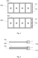
- Fig. 3 shows two top views, one above the other, of an embodiment of the spacing device 100.
- a top view of a section of a circulating conveyor belt 113 is shown, which is Tow bars 117 are pulled through the lamination system.
- both a conveyor belt 113 and a release belt 115 are attached to such tow bars 117 and are guided by them through one or more laminate chambers or parts of the lamination system.
- the conveyor belt 113 can be continuous or interrupted; in particular, a further section of the conveyor belt 113 can be adjacent to the right-hand side of the tow bar 117, or the conveyor belt 113 can be interrupted there.
- the direction of rotation of which points, for example, towards the right edge of the image several laminates 30 lie in frames 150 formed from spacer elements 120.
- the spacer elements 120 are attached directly to the conveyor belt 113.
- the frames 150 can also have spacer elements 120 made of stretchable or flexible, yet pressure-resistant material that extend in the transport direction, allowing the frames 150 to circulate.
- the frames 150 for the individual laminates 30 are designed as a spacing element 120, which is not attached directly to the conveyor belt, but like the conveyor belt 113 to the towing bar 117 and is guided by it.
- Fig. 4 shows a cross section for the embodiment in the lower part of the Figure 3 . Visible are a lower tow bar 117 and an upper tow bar 118, for a direction of rotation pointing to the right in the image.
- a conveyor belt 113 is attached to the lower tow bar 117, and a release belt 115 to the upper tow bar 118. Both tow bars 117, 118 pull the belts 113, 115 through the lamination system.
- the belts 113, 115 can each be continuous or interrupted; in particular, another section of the respective belt 113, 115 can be adjacent to the right side of the tow bars 117, 118, or the respective belt 113, 115 can be interrupted there.
- a spacing element 120 is also attached to the lower tow bar 117, which rests on the conveyor belt 113.
- the spacing element 120 can, for example, be screwed, welded, or clamped to the tow bar 117.
- the spacer element 120 has frames 150 for one or more laminates 30 (not shown here). Alternatively, the spacer element 120 could also be attached to the tow bar 118 and pulled by it.
- Fig. 5 shows further details of spacing elements 120 for an embodiment of the spacing device 100. Shown is a cross-section through a conveyor belt 113, a laminate 30 framed by spacing elements 120, and part of a membrane holding device 200.
- the spacing elements 120 are connected to the conveyor belt 113. They have a shape which is intended to allow material to escape from the laminate 30 during lamination. In particular, EVA, for example, can be removed from the plastic layer 37 (cf. Figure 6 ) escape from the laminate 30 during lamination.
- the shape of the spacer elements 120 is the bevels 125. The spacer elements 120 reduce the outflow of encapsulation material because the laminate edges are not over-pressed. The risk of sticking is thereby already reduced or minimized.
- the spacer elements 120 are given a bevel to the laminate edge by the bevels 125 so that any encapsulation material flowing out has as little contact surface as possible with the spacer elements 120. Escaping material reaches the conveyor belt 113 through this shape. It is advantageous if the spacer elements 120, like the conveyor belt 113, have a non-stick coating made of material which prevents escaping material from sticking (such as Teflon).
- the outer spacer elements 120 have bevels 122 that serve to protect the membrane 210 (not shown here) pressed on from above. Sharp edges can damage the membrane 210, whose thickness can be less than one centimeter; the bevels 122 allow the membrane 210 to conform over a larger area, thus increasing the service life of the membrane 210.
- Fig. 7 shows steps of a method for producing a spacing device 100 for a system for laminating a laminate 30, in particular a photovoltaic module, wherein the system comprises a membrane holding device 200, which is designed to apply a membrane 210 for lamination to the laminate 30 under the application of pressure.
- a first step comprises providing S100 a circumferential belt 110, which may be part of an existing system.
- a further step comprises attaching S200 a plurality of spacer elements 120 to the circumferential belt 110 in such a way that the spacer elements 120 at least partially form a frame 150 around the laminate 30 during lamination and thereby suppress edge compression of the laminate 30 during lamination when the membrane 210 is applied to the laminate 30.
Landscapes
- Engineering & Computer Science (AREA)
- Physics & Mathematics (AREA)
- Fluid Mechanics (AREA)
- Mechanical Engineering (AREA)
- Quality & Reliability (AREA)
- Thermal Sciences (AREA)
- Lining Or Joining Of Plastics Or The Like (AREA)
- Photovoltaic Devices (AREA)
Description
- Die vorliegende Erfindung bezieht sich auf eine Beabstandungsvorrichtung für ein System zum Laminieren eines Laminats, insbesondere von Photovoltaikmodulen, mit einer Membran, und auf ein Verfahren zur Herstellung einer solchen Beabstandungsvorrichtung.
- Eine Produktion von Photovoltaikmodulen umfasst ein Laminieren von Schichten eines Laminats (Schichtstapel) unter Druck und erhöhter Temperatur. Für dieses Laminieren ist die Verwendung sogenannter Membran-Laminatoren verbreitet. Das Laminieren kann dabei weitgehend automatisiert durch ein System erfolgen, das insbesondere eine Vielzahl solcher Laminate in eine Laminationskammer transportiert, in der eine in einem Spannrahmen eingespannte Membran von oben auf das zu laminierende Laminat gedrückt wird. Gleichzeitig wird dem Laminat Wärme zugeführt und durch eine Absaugeinrichtung der Druck um das Laminat gesenkt, wodurch der Druck der Membran erhöht oder bewirkt werden kann.
- Unter dem Druck der Membran, deren Fläche über die des Laminats hinausreicht, kann es dabei in Randbereichen des Laminats zu einer Überpressung kommen. Dies kann zu einer sogenannten Kantenverpressung bzw. zu "edge pinching", einer Verminderung der Dicke im Randbereich des Laminats, führen. Dadurch können Zugkräfte innerhalb des Laminats entstehen, die unmittelbar im Anschluss an die Produktion oder über längere Zeit eine Delamination oder auch beispielsweise einen Bruch einer Abdeckglasschicht bewirken können.
-
Fig. 6 zeigt eine Darstellung für ein Zustandekommen einer solchen Kantenverpressung. Auf der linken Seite der Figur ist ein Querschnitt eines Systems zum Laminieren eines Laminats 30 dargestellt. Eine Membran 210 wird zum Laminieren auf das Laminat 30 aufgedrückt (z.B. durch Ausbildung eines geeigneten Luftüberdrucks oder Luftunterdrucks). In Membranlaminatoren kann eine solche Membran 210 beispielsweise eine Dicke von bis zu 8 mm und eine Fläche in einer Größenordnung von bis zu mehreren Quadratmetern aufweisen. In den Randbereichen des Laminats 30 überragt eine Fläche der Membran 210 das Laminat 30, wodurch ein mechanischer Druck, der durch die Membran 210 auf das Laminat 30 ausgeübt wird, das Laminat 30 dort stärker presst als in einem Mittelbereich des Laminats 30. Dadurch entsteht die Kantenverpressung des Laminats. Die rechte Seite der Figur zeigt vergrößert den verpressten Randbereich des Laminats 30 im Querschnitt. Das Laminat 30 umfasst hier zwei Glasschichten 33, angeordnet um eine Schicht 37, die einen Kunststoff und darin eingelassene Solarzellen aufweist. Glasschichten können beispielsweise Dicken von bis zu 2,5 mm, die Kunststoffschicht beispielsweise eine Dicke im Bereich eines Millimeters aufweisen, so dass das Laminat 30 unverpresst beispielsweise eine Dicke von 5 mm besitzen kann. Zum Rand des Laminats 30 (auf der rechten Seite der Figur) hin ist die Dicke des Laminats 30 aufgrund der Überpressung vermindert. Dadurch werden anhaltende Spannung verursacht, die die Lebensdauer und Qualität der Photovoltaikmodule einschränken. - Eine Vorrichtung nach dem Stand der Technik ist aus dem Dokument
WO 2014/046810 A1 bekannt. - Es besteht ein Bedarf nach einer kostengünstigen und effizienten Unterdrückung der Kantenverpressung in Membran-Laminatoren, die sich vorteilhafterweise zudem für eine Nachrüstung von sich bereits im Betrieb befindlichen Membran-Laminatoren eignet, so dass bestehende automatisierte Prozesse weiterhin beibehalten werden können.
- Die oben genannte Aufgabe wird durch eine Beabstandungsvorrichtung nach Anspruch 1 und ein Verfahren zur Herstellung einer Beabstandungsvorrichtung nach Anspruch 11 gelöst. Die abhängigen Ansprüche beziehen sich auf vorteilhafte Weiterbildungen der Gegenstände der unabhängigen Ansprüche.
- Die vorliegende Erfindung bezieht sich auf eine Beabstandungsvorrichtung für ein System zum Laminieren eines Laminats, insbesondere von Photovoltaikmodulen. Das System umfasst eine Membranhalteeinrichtung, die ausgebildet ist, um zum Laminieren eine Membran auf das Laminat unter Ausübung eines Drucks aufzubringen. Die Beabstandungsvorrichtung weist ein umlaufendes Band, eine Vielzahl von Beabstandungselementen, die mit dem Band verbunden und ausgebildet sind, um zumindest in einem Abschnitt des Bandes zumindest teilweise einen Rahmen für das Laminat zu bilden und dadurch beim Laminieren eine Kantenverpressung des Laminats zu unterdrücken und zumindest eine Schleppstange auf, die lösbar mit den Beabstandungselementen verbindbar ist und der zumindest teilweise ausgebildete Rahmen an der zumindest einen Schleppstange befestigt ist.
- Die Membran kann dabei insbesondere in einem Spannrahmen gehalten werden, der auf das Laminat abgesenkt wird. Der Druck auf das Laminat kann dabei indirekt, also nicht durch einen direkten Kontakt, ausgeübt werden. Insbesondere kann beim Laminieren zwischen der Membran und dem Laminat eine Plane zum Schutz und zur besseren Ablösung der Membran vom Laminat nach dem Laminieren (ein sogenanntes "Releasesheet") liegen. Die Fläche der Membran überragt eine entsprechende Fläche des Laminats, und der durch die Beabstandungselemente teilweise ausgebildete Rahmen stützt die Membran neben dem Laminat in einer Weise ab, die geeignet ist, einen insbesondere durch die Spannung der Membran herrührenden erhöhten Druck im Randbereich des Laminats zu vermindern.
- Der durch die Beabstandungselemente ausgebildete Rahmen kann nur teilweise sein; er braucht das Laminat insbesondere nicht vollständig zu umschließen. Ein Abstützen der Membran an bestimmten geeigneten Stellen kann für eine Verminderung der Kantenbelastung ausreichend sein. Zudem - oder alternativ - können Aussparungen des Rahmens durch eine Geometrie des Systems bedingt sein. Der Rahmen kann auch erst in Kombination von Beabstandungselementen ausgebildet werden, die auf mehrere Bänder verteilt sind.
- Die Beabstandungselemente sind so ausgebildet, dass sie mit dem Band umlaufen können. Sie können jeweils einzeln direkt mit dem Band verbunden - beispielsweise aufgeklebt, aufgeschweißt, angenäht oder angeschraubt - sein. In Ausführungsbeispielen weist das Band zu seiner umlaufenden Bewegung aber auch Schleppstangen auf, und die Beabstandungselemente können einen zumindest teilweise ausgebildeten Rahmen umfassen, der an einer oder mehreren der Schleppstangen befestigt ist und mit dem Band umläuft. Dazu ist der Rahmen vorteilhafterweise ausgebildet, um in Umlaufrichtung flexibel, aber vertikal zum Band druckbeständig und formstabil zu sein. Dies kann beispielsweise durch Einbringen eines geeigneten Kunststoffmaterials (etwa Gummi) oder Metalls (etwa Kettenbänder) erreicht werden, welches den Rahmen ganz oder auch nur teilweise bildet.
- Dementsprechend können die Beabstandungselemente sowohl flexibles Material wie beispielsweise Silikon- oder Teflonmaterialien oder Ethylen-Propylen-DienKautschuk wie EPDM oder nichtflexibles Material wie beispielsweise Aluminium oder Stahl aufweisen. Flexible Materialien können dabei insbesondere dem Umlaufen der Beabstandungselemente dienen und als durchgehende Formen, als Bänder, Schnüre, und/oder Seile, als Segmente mit Abständen zwischen einander oder auch in Komposition mit nichtflexiblen Materialien auftreten. Nichtflexible Materialien können beispielsweise als Kettenbänder, als Reißverschluss oder auch als Stangen, Zähne oder Stützelemente für die Beabstandungselemente verwendet sein.
- Optional umfasst das Laminieren ein Ausbilden eines Unterdruckes, und die Beabstandungselemente sind so ausgebildet, dass der ausgebildete Rahmen Öffnungen aufweist, um beim Laminieren einen Austritt von Gas aus einem Bereich in oder um das Laminat zu begünstigen.
- Beispielsweise existieren Membranlaminationssysteme, bei denen der Druck der Membran auf das Laminat zumindest teilweise durch ein Erzeugen eines Unterdrucks im Bereich um das Laminat aufgebaut wird. Alternativ oder zusätzlich fördert ein Evakuieren um das Laminat während des Laminierens einen Austritt von Luft aus dem Laminat. Dies kann insbesondere auch einer Vorbeugung von Luft- oder anderen Gaseinschlüssen im Laminat dienen.
- Optional erfolgt beim Laminieren eine Verschmelzung von Kunststoff in dem Laminat, und die Beabstandungselemente sind so ausgebildet, dass der ausgebildete Rahmen Aussparungen aufweist oder einen Spalt zu dem Laminat bildet, dass austretender Kunststoff beim Laminieren aufgenommen bzw. abgeführt werden kann.
- Ein Laminat für Photovoltaikmodule kann beispielsweise u.a. eine zwischen zwei Glasplatten gelagerte Schicht eines Kunststoffmaterials wie etwa Ethylenvinylacetat (EVA) oder Polyolefin (PO) umfassen, welches eine Vielzahl von Photovoltaikzellen sowie zugehörige Kontaktierungen einschließt. Beim Laminieren kann solches Kunststoffmaterial seitlich zwischen den Glasplatten aus dem Laminat austreten. Die Beabstandungselemente können ausgebildet sein, um beispielsweise durch ein geeignete Form eines aus den Beabstandungselementen gebildeten Rahmens diesen Austritt von Kunststoffmaterial zu ermöglichen und/oder zu begünstigen. So kann der Rahmen etwa auf einer dem Laminat zugewandten Seite Einbuchtungen, Verbreiterungen, Nuten, Kanäle und/oder sonstige Aussparungen aufweisen, die einen ausreichenden Platz für austretendes geschmolzenes Kunststoffmaterial bzw. Einkapselungsmaterial bieten.
- Optional ist die Membranhalteeinrichtung ausgebildet, um die Membran in einer vertikalen Bewegung auf das Laminat aufzubringen, und die Beabstandungselemente sind so ausgebildet, dass beim Aufbringen der Membran auf das Laminat der ausgebildete Rahmen mit dem Laminat bündig abschließt.
- Der bündige Abschluss soll ein übermäßiges Durchbiegen der Membran, wie es bei konventionellen Systemen der Fall ist, verhindern. Das kann beispielsweise dadurch erreicht werden, dass die Beabstandungselemente eine gleiche Höhe aufweisen wie das zu fertigende Laminat, und/oder zumindest auf einer der Membran zugewandten Seite möglichst nahe an Laminat heranreichen.
- Die Höhe der Beabstandungselemente kann die Höhe des Laminats auch übertreffen. Insbesondere kann dies der Fall sein, wenn beim Pressen der Membran auf das Laminat ein Abstand zwischen dem Laminat und den Beabstandungselementen vorliegt; die Beabstandungselemente können das Laminat beispielsweise um einige Prozent der Dicke des Laminats überragen. Eine Höhe der Beabstandungselemente kann von dem Abstand zwischen dem Laminat und den Beabstandungselementen abhängen.
- Optional weisen die Beabstandungselemente zumindest eines der folgenden Materialien auf: Stahl, Kunststoff, Silikon, Hartgummi, ein Basismaterial mit einer Antihaftbeschichtung.
- Optional sind die Beabstandungselemente austauschbar mit dem umlaufenden Band verbunden, um Rahmen zu bilden, die eine an verschiedene Laminate angepasste Größe und/oder Höhe aufweisen.
- So könnten beispielsweise lediglich Halterungen an dem umlaufenden Band befestigt sein, in welche jeweils für bestimmte Laminate geeignete Elemente eingesteckt werden können, um die Beabstandungselemente zu bilden. Sind die Beabstandungselemente mit einer Schleppstange des Bandes verbunden ausgeführt, kann die Verbindung mit der Schleppstange lösbar sein, so dass verschiedene Beabstandungselemente für entsprechend verschiedene Laminate mit der Schleppstange verbunden werden können.
- Optional ist das umlaufende Band ein Transportband, das ausgebildet, um darauf das Laminat aufzulegen und zumindest teilweise durch das System zum Laminieren zu transportieren, oder ein Releaseband, das ausgebildet, um beim Laminieren zwischen der Membran und dem Laminat zu liegen und nach dem Laminieren eine Ablösung der Membran vom Laminat zu begünstigen.
- Das Transportband bzw. Transportsheet kann insbesondere ein Material wie z.B. Teflon aufweisen, das geeignet ist, das Laminat nach dem Laminieren leicht vom Transportband abzuheben und eine Anhaftung von aus dem Laminat austretendem Material zu verhindern. Zudem ist das Transportband vorteilhafterweise ausreichend druck- und hitzebeständig, um während des Laminierens seine Funktion als Ablage des Laminats gewährleisten zu können. Das Releaseband bzw. Releasesheet kann zudem ausgebildet sein, um das Laminat zu schützen.
- Optional umfasst die Beabstandungsvorrichtung als umlaufendes Band ein Releasesheet, auf dem Beabstandungselemente aufgebracht sind, und dazu ein weiteres umlaufendes Band mit weiteren Beabstandungselementen, wobei das weitere umlaufende Band ein Transportband ist, das ausgebildet ist, um das Laminat zum Laminieren zu transportieren. Zudem können die weiteren Beabstandungselemente des Transportbands so ausgebildet sein, dass sie mit zumindest einigen der Beabstandungselemente beim Laminieren in Eingriff gelangen, und so einen stufenlosen Rahmen für das Laminat bilden, umdadurch beim Laminieren die Kantenverpressung des Laminats zu unterdrücken.
- Der Begriff stufenlos soll dabei insbesondere eine gleichmäßige Höhe des Rahmens bedeuten. Beispielsweise ist eine Befestigung der Beabstandungselemente an dem sich unterhalb der Laminate befindenden Transport-Sheet möglich, aber auch an dem sich oberhalb der Laminate befindenden Release-Sheet. Ebenso kann ein Teil der Aufbauhöhe des Rahmens auf dem Transport-Sheet und der andere Teil der Aufbauhöhe auf dem Release-Sheet aufgebracht werden, sodass die Zielhöhe des Rahmens erreicht wird, wenn beide Aufbauhöhen im Prozess des Laminierens übereinander liegen.
- Optional umfasst die Vielzahl von Beabstandungselementen zumindest zwei Beabstandungselemente, die ausgebildet sind, um bei der Bildung des zumindest teilweisen Rahmens während des Laminierens reißverschlussartig ineinanderzugreifen.
- Die ineinandergreifenden Beabstandungselemente können an demselben Band oder an verschiedenen Bändern angebracht sein.
- Optional kann weiter mindestens eines der Beabstandungselemente eine Abschrägung aufweisen, um eine Standzeit oder Lebensdauer der Membran zu verlängern. Ohne Abschrägungen können scharfe Kanten der Beabstandungselemente in die Membran einschneiden und diese so beschädigen. Alternativ oder zusätzlich ist die Form auch geeignet, um eine Kraft in horizontale Kraft Richtung zu dem Laminat auszuüben, wodurch Zwischenräume zwischen den Beabstandungselementen und dem Laminat verringert werden können, um so Lufteinschlüsse zu minimieren (zumindest, wenn die Beabstandungselemente eine gewisse Flexibilität aufweisen).
- Die vorliegende Erfindung bezieht sich zudem auf ein Verfahren zu einer Herstellung einer Beabstandungsvorrichtung für ein System zum Laminieren eines Laminats, insbesondere eines Photovoltaikmoduls. Dabei umfasst das System eine Membranhalteeinrichtung, die ausgebildet ist, um eine Membran zum Laminieren auf das Laminat unter Ausübung eines mechanischen Drucks aufzubringen. Das Verfahren umfasst folgende Schritte:
- Bereitstellen eines umlaufenden Bands;
- Befestigen einer Vielzahl von Beabstandungselementen an dem umlaufenden Band, so dass die Beabstandungselemente während des Laminierens zumindest teilweise einen Rahmen um das Laminat bilden und dadurch beim Aufbringen der Membran auf das Laminat eine Kantenverpressung des Laminats beim Laminieren unterdrücken;
- lösbares Verbinden zumindest einer Schleppstange mit den Beabstandungselementen, wobei der zumindest teilweise ausgebildete Rahmen an der zumindest einen Schleppstange befestigt ist.
- Die Beabstandungsvorrichtung soll somit insbesondere ein Durchbiegen der Kante des Laminats beim Laminieren verhindern, und zwar durch eine mechanische Abstützung, die durch die Beabstandungselemente bewirkt wird. Die Beabstandungselemente stützen dabei die Membran direkt und/oder indirekt (beispielsweise bei einem zwischen Membran und Beabstandungsvorrichtung verlaufendem Releasesheet) in einer über das Laminat hinausragenden Fläche der Membran so ab, dass zusätzlicher Druck, der im Randbereich des Laminats durch die Spannung der Membran ausgeübt wird, zumindest reduziert wird.
- Vorteile von Ausführungsbeispielen einer Beabstandungsvorrichtung wie vorangehend beschrieben umfassen dabei insbesondere auch die Möglichkeit einer kostengünstige Fertigung, welche lediglich einer Geometrie eines bereits bestehenden Systems zum Membranlaminieren angepasst werden und in ein solches auch nachträglich eingebaut werden kann.
- Die Ausführungsbeispiele der vorliegenden Erfindung werden besser verstanden von der folgenden detaillierten Beschreibung und den beiliegenden Zeichnungen, die jedoch nicht so verstanden werden sollten, dass sie die Offenbarung auf die spezifischen Ausführungsformen einschränken, sondern lediglich der Erklärung und dem Verständnis dienen.
- Fig. 1
- zeigt eine Beabstandungsvorrichtung für ein System zum Laminieren eines Laminats.
- Fig. 2
- zeigt zweimal einen Querschnitt eines weiteren Ausführungsbeispiels für eine Beabstandungsvorrichtung für ein System zum Laminieren eines Laminats.
- Fig. 3
- zeigt Aufsichten auf zwei Ausführungsbeispiele für die Beabstandungsvorrichtung für ein Transportband, welches an Schleppstangen geführt wird.
- Fig. 4
- zeigt einen Querschnitt für eine an Schleppstangen befestigte Beabstandungsvorrichtung.
- Fig. 5
- zeigt weitere Details von Beabstandungselementen in einem Querschnitt eines Systems zum Laminieren mit Beabstandungsvorrichtung.
- Fig. 6
- zeigt eine Darstellung für ein Zustandekommen einer Kantenverpressung in einem herkömmlichen System zum Laminieren ohne Beabstandungsvorrichtung.
- Fig. 7
- zeigt Schritte eines Verfahrens zur Herstellung einer Beabstandungsvorrichtung für ein System zum Laminieren eines Laminats mit einer Membran.
-
Fig. 1 zeigt ein Ausführungsbeispiel für eine Beabstandungsvorrichtung 100 für ein System zum Laminieren eines Laminats 30, insbesondere von Photovoltaikmodulen. Das System umfasst eine Membranhalteeinrichtung 200, die ausgebildet ist, um zum Laminieren eine Membran 210 auf das Laminat 30 unter Ausübung eines Drucks aufzubringen. Die Beabstandungsvorrichtung 100 umfasst ein umlaufendes, über Umlenkrollen geführtes Band 110 und eine Vielzahl von Beabstandungselementen 120, die mit dem Band verbunden und ausgebildet sind, um zumindest in einem Abschnitt des umlaufenden Bandes 110 einen Rahmen 150 für das Laminat 30 zu bilden und dadurch beim Laminieren eine Kantenverpressung des Laminats 30 durch die Membran 210 zu unterdrücken. - Um die Randverpressung durch die Membran 210 zu vermeiden, sollte die aktive Pressfläche der Membran 210 nicht größer sein als das zu fertigende Laminat 30. Dies wird hier durch die Vielzahl von Beabstandungselementen 120, die Rahmen 150 für das Laminat 30 bilden, erreicht. Der Rahmen 150 ist vorteilhafterweise nur unwesentlich größer als die Laminat-Außenkanten und hat zumindest die Höhe des zu fertigenden Laminats 30. Das Laminat 30 wird vorteilhafterweise vor Prozessstart im Laminationsrahmen 150 platziert. Durch den Schutz des Rahmens 150 vor Überpressung der Kanten durch die Membran 210 können Laminate 30 ohne Randverpressung gefertigt werden. Ein Abstand der Beabstandungselemente 120 vom Laminat 30 ist auch von einer Ablagegenauigkeit des Laminats 30 auf dem Band 110 abhängig. Die Ablagegenauigkeit variiert zwischen verschiedenen Systemen zum Laminieren. In Beispielen kann der Abstand zwischen Laminat 30 und Rahmen 150 in einer Größenordnung von 3 bis 7 mm liegen. Das Ausführungsbeispiel ermöglicht so einen automatisierten Prozess ohne manuelles Handling und Laminate 30 ohne Rand- bzw. Kantenverpressung.
- In der dargestellten Figur übernimmt das umlaufende Band 110 insbesondere den Transport des Laminats 30 durch zumindest Teile des Systems zum Laminieren. Auf einem solchen Transportsheet werden die Laminate 30 eingefördert und vor Prozessstart abgelegt. Ausführungen, in denen ein anderes Band 110 als das Transportsheet mit Beabstandungselementen 120 ausgebildet ist, sind denkbar. Insbesondere können mehrere Bänder 110 existieren, deren jeweilige Beabstandungselemente 120 beim Laminieren gemeinsam einen Rahmen 150 für das Laminat 30 bilden. Dazu können die Beabstandungselemente 120 auch nach Art eines Reißverschlusses ineinandergreifen.
- Die Beabstandungselemente 120 sind in der dargestellten Figur auf dem Band 110 fixiert. Die Beabstandungselemente 120 können auch größere Rahmen 150 bildende Strukturen sein, die nur an bestimmten Stellen mit dem Band 110 verbunden sein müssen. Die Beabstandungselemente 120 können auswechselbar sein, so dass mit verschiedenen Beabstandungselementen 120 Rahmen 150 für verschiedene Laminate 30 gebildet werden können.
-
Fig. 2 zeigt übereinander angeordnet zwei Mal einen Querschnitt durch einen Teil eines Systems zum Laminieren mit einer Membranhalteeinrichtung 200 und einer Membran 210, die zum Laminieren auf ein Laminat 30 aufgebracht wird. Das Laminat 30 liegt auf einem umlaufenden Transportband bzw. Transportsheet 113 über einer Heizplatte 300. Zwischen der Membran 210 und dem Laminat 30 verläuft ein ebenfalls umlaufendes Releaseband 115, welches das Laminat 30 beispielsweise vor Verschmutzung schützt und ein Abheben der Membran 210 vom Laminat 30 nach dem Laminieren erleichtert. In Systemen zum Laminieren kann eine Dicke des Releasesheets 300 beispielsweise 0.3 mm betragen. Neben dem Laminat 30 sind Beabstandungselemente 120 dargestellt, die ein Überpressen der Kanten des Laminats 30 durch die Membran 210 verhindern sollen. Im dargestellten Ausführungsbeispiel werden die Beabstandungselemente 120 an den Sheets 113, 115 im Laminator befestigt. Hierbei ist eine Befestigung an dem sich unterhalb des Laminats 30 befindenden Transportsheet 113 und/oder an dem sich oberhalb des Laminats 30 befindenden Release-Sheet 115 möglich. Der durch die Beabstandungselemente 120 gebildete Rahmen 150 kann Öffnungen aufweisen, die senkrecht zum Laminat 30 positioniert sind und eine Evakuierung eines Bereichs um die Laminate 30 erleichtern. Abschrägungen 122 an Kanten der Beabstandungselemente 120 erhöhen die Standzeit der Membran 210. - Im oben in der Figur dargestellten Querschnitt wird die Membran 210 auf das Laminat 30 bzw. auf das Releasesheet 115 abgesenkt. Dadurch schließt die Membran 210 um das Laminat 30 eine Laminatkammer ab. Im unteren Querschnitt ist durch die Pfeile oberhalb der Membran 210 ein Druck dargestellt, der die Membran 210 auf Releasesheet 115 und Laminat 30 drückt. Der Druck kann beispielsweise durch einen Überdruck eines Fluids (z.B.Luft) oberhalb der Membran 210, aber auch durch eine Evakuierung von Luft aus der Laminatkammer erzeugt oder unterstützt werden. Während des Laminierens wird über eine unterhalb des Transportsheets 113 dargestellte Heizplatte 300 dem Laminat 30 zum Laminieren Wärme zugeführt.
-
Fig. 3 zeigt übereinander zwei Aufsichten auf jeweils ein Ausführungsbeispiel für die Beabstandungsvorrichtung 100. In beiden Teilen der Figur ist jeweils eine Aufsicht auf einen Abschnitt eines umlaufenden Transportbands 113 dargestellt, welches über Schleppstangen 117 durch das System zum Laminieren gezogen wird. In Beispielen für Membranlaminationssysteme sind sowohl ein Transportband 113 als auch ein Releaseband 115 (hier nicht dargestellt) an solchen Schleppstangen 117 befestigt und werden von diesen durch eine oder mehrere Laminatkammern bzw. Teile des Systems zum Laminieren geführt. Das Transportband 113 kann durchgehend oder auch unterbrochen sein; insbesondere kann auf der rechten Seite der Schleppstange 117 jeweils ein weiterer Abschnitt des Transportbands 113 angrenzen, oder das Transportband 113 kann dort unterbrochen sein. Auf dem Transportband 113, dessen Umlaufrichtung jeweils beispielsweise in Richtung des rechten Bildrands weist, liegen mehrere Laminate 30 in aus Beabstandungselementen 120 gebildeten Rahmen 150. - Im oberen Teil der Figur sind die Beabstandungselemente 120 direkt auf das Transportband 113 befestigt. Die Rahmen 150 können auch in Transportrichtung ausgedehnte Beabstandungselemente 120 aus dehnbarem bzw. flexiblem, aber druckfestem Material aufweisen, das ein Umlaufen der Rahmen 150 ermöglicht.
- Im unteren Teil der Figur sind die Rahmen 150 für die einzelnen Laminate 30 als ein Beabstandungselement 120 ausgeführt, das nicht direkt am Transportband, sondern wie das Transportband 113 an der Schleppstange 117 befestigt und wird von dieser geführt wird.
-
Fig. 4 zeigt einen Querschnitt für das Ausführungsbeispiel im unteren Teil derFigur 3 . Zu sehen ist eine untere Schleppstange 117 und eine obere Schleppstange 118, für eine nach rechts im Bild weisende Umlaufrichtung. An der unteren Schleppstange 117 ist ein Transportband 113 befestigt, an der obere Schleppstange 118 ein Releaseband 115. Beide Schleppstangen 117, 118 ziehen die Bänder 113, 115 durch das System zum Laminieren. Die Bänder 113, 115 können dabei jeweils durchgehend oder auch unterbrochen sein; insbesondere kann jeweils auf der rechten Seite der Schleppstangen 117, 118 ein weiterer Abschnitt des jeweiligen Bandes 113, 115 angrenzen, oder das jeweilige Band 113, 115 kann dort unterbrochen sein. - An der unteren Schleppstange 117 ist zudem ein Beabstandungselement 120 befestigt, welches auf dem Transportband 113 aufliegt. Das Beabstandungselement 120 kann beispielsweise an der Schleppstange 117 geschraubt, geschweißt oder geklemmt sein.
- Das Beabstandungselement 120 weist Rahmen 150 für ein oder mehrere Laminate 30 auf (hier nicht dargestellt). Das Beabstandungselement 120 könnte alternativ auch an der Schleppstange 118 befestigt sein und von dieser gezogen werden.
-
Fig. 5 zeigt weitere Details von Beabstandungselementen 120 für ein Ausführungsbeispiel der Beabstandungsvorrichtung 100. Gezeigt ist ein Querschnitt durch ein Transportband 113, ein von Beabstandungselementen 120 eingerahmtes Laminat 30 sowie ein Teil einer Membranhalteeinrichtung 200. Die Beabstandungselemente 120 sind dabei mit dem Transportband 113 verbunden. Sie weisen eine Form auf, welche ein Austreten von Material aus dem Laminat 30 während des Laminierens ermöglichen soll. Insbesondere kann beispielsweise EVA aus der Kunststoffschicht 37 (vgl.Figur 6 ) beim Laminieren aus dem Laminat 30 austreten. Im dargestellten Ausführungsbeispiel handelt es sich bei der Form der Beabstandungselemente 120 um die Abschrägungen 125. Durch die Beabstandungselemente 120 wird ein Ausfluss von Einkapselungsmaterial reduziert, da die Laminatkanten nicht überpresst werden. Das Risiko des Verklebens wird dadurch bereits verringert oder minimiert. Die Beabstandungselemente 120 erhalten durch die Abschrägungen 125 eine Schräge zur Laminatkante, damit herausfließendes Einkapselungsmaterial möglichst wenig Kontaktfläche mit den Beabstandungselementen 120 hat. Austretendes Material gelangt durch diese Form auf das Transportband 113. Dabei ist es vorteilhaft, wenn die Beabstandungselemente 120 ebenso wie das Transportband 113 eine Antihaftbeschichtung aus Material aufweist, welches ein Anhaften von ausgetretenem Material verhindert (wie z.B. Teflon). - Zudem weisen die äusseren Beabstandungselemente 120 Abschrägungen 122 auf, die dem Schutz der von oben aufgedrückten Membran 210 (hier nicht dargestellt) dienen. Scharfe Kanten können die Membran 210, deren Dicke im Bereich unter einem Zentimeter liegen kann, verletzen; die Abschrägungen 122 erlauben ein Anschmiegen der Membran 210 über eine größere Fläche und erhöhen so eine Standzeit der Membran 210.
-
Fig. 7 zeigt Schritte eines Verfahrens zur Herstellung einer Beabstandungsvorrichtung 100 für ein System zum Laminieren eines Laminats 30, insbesondere eines Photovoltaikmoduls, wobei das System eine Membranhalteeinrichtung 200 umfasst, die ausgebildet ist, um eine Membran 210 zum Laminieren auf das Laminat 30 unter Ausübung eines Drucks aufzubringen. Ein erster Schritt umfasst ein Bereitstellen S100 eines umlaufenden Bands 110, welches Teil eines bestehenden Systems sein kann. Ein weiterer Schritt umfasst ein Befestigen S200 einer Vielzahl von Beabstandungselementen 120 an dem umlaufenden Band 110, auf eine Weise, dass die Beabstandungselemente 120 während des Laminierens zumindest teilweise einen Rahmen 150 um das Laminat 30 bilden und dadurch beim Aufbringen der Membran 210 auf das Laminat 30 eine Kantenverpressung des Laminats 30 beim Laminieren unterdrücken. - Die in der Beschreibung, den Ansprüchen und den Figuren offenbarten Merkmale der Erfindung können sowohl einzeln als auch in beliebiger Kombination für die Verwirklichung der Erfindung wesentlich sein.
-
- 30
- Laminat
- 100
- Beabstandungsvorrichtung
- 110
- umlaufendes Band
- 113
- Transportband (Transportsheet)
- 115
- Releaseband (Releasesheet)
- 117, 118
- Schleppstangen
- 120
- Beabstandungselemente
- 122
- Abschrägung zur Erhöhung einer Membranstandzeit
- 125
- Aussparung zur Aufnahme von austretendem Material
- 150
- Rahmen
- 200
- Membranhalteeinrichtung
- 210
- Membran
- 300
- Heizplatte
Claims (11)
- Eine Beabstandungsvorrichtung (100) für ein System zum Laminieren eines Laminats (30), insbesondere von Photovoltaikmodulen, wobei das System eine Membranhalteeinrichtung (200) umfasst, die ausgebildet ist, um zum Laminieren eine Membran (210) auf das Laminat (30) unter Ausübung eines Drucks aufzubringen, die Beabstandungsvorrichtung (100) umfasst:ein umlaufendes Band (110);eine Vielzahl von Beabstandungselementen (120), die mit dem Band verbunden und ausgebildet sind, um zumindest in einem Abschnitt des umlaufenden Bandes (110) zumindest teilweise einen Rahmen (150) für das Laminat (30) zu bilden und dadurch beim Laminieren eine Kantenverpressung des Laminats (30) zu unterdrücken;dadurch gekennzeichnet, dass die Beabstandungsvorrichtung zumindest eine Schleppstange (117, 118) umfasst, die lösbar mit den Beabstandungselementen (120) verbindbar ist und der zumindest teilweise ausgebildete Rahmen (150) an der zumindest einen Schleppstange (117, 118) befestigt ist.
- Die Beabstandungsvorrichtung (100) nach Anspruch 1, wobei das Laminieren ein Ausbilden eines Unterdruckes umfasst, und wobei
die Beabstandungselemente (120) so ausgebildet sind, dass der ausgebildete Rahmen (150) Öffnungen aufweist, um beim Laminieren einen Austritt von Gas aus einem Bereich in oder um das Laminat (30) zu begünstigen. - Die Beabstandungsvorrichtung (100) nach einem der vorhergehenden Ansprüche, wobei beim Laminieren eine Verschmelzung von Kunststoff in dem Laminat (30) erfolgt, und wobei
die Beabstandungselemente (120) so ausgebildet sind, dass der ausgebildete Rahmen (150) Aussparungen (125) aufweist oder einen Spalt zu dem Laminat (30) bildet, um austretenden Kunststoff beim Laminieren aufzunehmen. - Die Beabstandungsvorrichtung (100) nach einem der vorhergehenden Ansprüche,
wobei die Membranhalteeinrichtung (200) ausgebildet ist, um die Membran (210) in einer vertikalen Bewegung auf das Laminat (30) aufzubringen, und wobei die Beabstandungselemente (120) so ausgebildet sind, dass beim Aufbringen der Membran (210) auf das Laminat (30) der ausgebildete Rahmen (150) mit dem Laminat (30) bündig abschließt. - Die Beabstandungsvorrichtung (100) nach einem der vorhergehenden Ansprüche, wobei die Beabstandungselemente (120) zumindest eines der folgenden Materialien aufweisen:- Stahl,- Kunststoff,- Silikon,- Hartgummi,- ein Basismaterial mit einer Antihaftbeschichtung.
- Die Beabstandungsvorrichtung (100) nach einem der vorangehenden Ansprüche, wobei die Beabstandungselemente (110) austauschbar mit dem umlaufenden Band verbunden sind, um Rahmen (150) zu bilden, die eine an verschiedene Laminate angepasste Größe und/oder Höhe aufweisen.
- Die Beabstandungsvorrichtung (100) nach einem der vorhergehenden Ansprüche, wobei das umlaufende Band (110) eines der folgenden ist:ein Transportband (113), das ausgebildet, um darauf das Laminat (30) aufzulegen und zumindest teilweise durch das System zum Laminieren zu transportieren,ein Releaseband (115), das ausgebildet, um beim Laminieren zwischen der Membran (210) und dem Laminat (30) zu liegen und nach dem Laminieren eine Ablösung der Membran (210) vom Laminat (30) zu begünstigen.
- Die Beabstandungsvorrichtung (100) nach einem der Ansprüche 1 bis 6, wobeidas umlaufende Band (110) ein Releaseband (115) ist, das ausgebildet ist, um beim Laminieren zwischen der Membran (210) und dem Laminat (30) zu liegen und nach dem Laminieren eine Ablösung der Membran (210) vom Laminat (30) zu begünstigen;und wobei die Beabstandungsvorrichtung (100) außerdem Folgendes umfasst:ein weiteres umlaufendes Band mit weiteren Beabstandungselementen, wobei das weitere umlaufende Band ein Transportband (113) ist, das ausgebildet ist, um das Laminat (30) zum Laminieren zu transportieren,und die weiteren Beabstandungselemente ausbildet sind, um mit zumindest einigen der Beabstandungselemente (120) beim Laminieren in Eingriff zu gelangen, um einen stufenlosen Rahmen (150) für das Laminat (30) zu bilden und dadurch beim Laminieren eine Kantenverpressung des Laminats (30) zu unterdrücken.
- Die Beabstandungsvorrichtung (100) nach Anspruch 8, wobei die Vielzahl von Beabstandungselementen (120) zumindest zwei Beabstandungselemente umfasst, die ausgebildet sind, um bei der Bildung des zumindest teilweisen Rahmens (150) während des Laminierens reißverschlussartig ineinanderzugreifen.
- Die Beabstandungsvorrichtung (100) nach einem der vorhergehenden Ansprüche, wobei mindestens eines der Beabstandungselemente (120) eine Abschrägung (122) aufweist, um eine Standzeit der Membran (210) zu verlängern und/oder geeignet ist, um beim Aufbringen der Membran (210) auf dem Laminat (30) durch den über die Membran (210) auf das Beabstandungselement ausgeübten mechanischen Druck einen Druck in Richtung des Laminats (30) aufzubauen.
- Ein Verfahren zur Herstellung einer Beabstandungsvorrichtung (100) für ein System zum Laminieren eines Laminats (30), insbesondere eines Photovoltaikmoduls, wobei das System eine Membranhalteeinrichtung (200) umfasst, die ausgebildet ist, um eine Membran (210) zum Laminieren auf das Laminat (30) unter Ausübung eines mechanischen Drucks aufzubringen, das Verfahren umfasst folgende Schritte:Bereitstellen (S100) eines umlaufenden Bands (110);Befestigen (S200) einer Vielzahl von Beabstandungselementen (120) an dem umlaufenden Band (110), so dass die Beabstandungselemente (120) während des Laminierens zumindest teilweise einen Rahmen (150) um das Laminat (30) bilden und dadurch beim Aufbringen der Membran (210) auf das Laminat (30) eine Kantenverpressung des Laminats (30) beim Laminieren unterdrücken;dadurch gekennzeichnet, dass das Verfahren ein lösbares Verbinden zumindest einer Schleppstange (117, 118) mit den Beabstandungselementen (120) umfasst, wobei der zumindest teilweise ausgebildete Rahmen (150) an der zumindest einen Schleppstange (117, 118) befestigt ist.
Priority Applications (2)
| Application Number | Priority Date | Filing Date | Title |
|---|---|---|---|
| SI202130343T SI4188710T1 (sl) | 2020-07-28 | 2021-07-26 | Distančna naprava za sistem za laminiranje |
| HRP20251017TT HRP20251017T1 (hr) | 2020-07-28 | 2021-07-26 | Odstojnik za sustav za laminiranje |
Applications Claiming Priority (2)
| Application Number | Priority Date | Filing Date | Title |
|---|---|---|---|
| DE102020119857.4A DE102020119857A1 (de) | 2020-07-28 | 2020-07-28 | Beabstandungsvorrichtung für ein System zum Laminieren |
| PCT/EP2021/070824 WO2022023248A1 (de) | 2020-07-28 | 2021-07-26 | Beabstandungsvorrichtung für ein system zum laminieren |
Publications (2)
| Publication Number | Publication Date |
|---|---|
| EP4188710A1 EP4188710A1 (de) | 2023-06-07 |
| EP4188710B1 true EP4188710B1 (de) | 2025-06-11 |
Family
ID=77180001
Family Applications (1)
| Application Number | Title | Priority Date | Filing Date |
|---|---|---|---|
| EP21749590.2A Active EP4188710B1 (de) | 2020-07-28 | 2021-07-26 | Beabstandungsvorrichtung für ein system zum laminieren |
Country Status (11)
| Country | Link |
|---|---|
| US (1) | US12391031B2 (de) |
| EP (1) | EP4188710B1 (de) |
| CN (1) | CN116368008A (de) |
| DE (1) | DE102020119857A1 (de) |
| ES (1) | ES3040113T3 (de) |
| HR (1) | HRP20251017T1 (de) |
| LT (1) | LT4188710T (de) |
| PL (1) | PL4188710T3 (de) |
| PT (1) | PT4188710T (de) |
| SI (1) | SI4188710T1 (de) |
| WO (1) | WO2022023248A1 (de) |
Family Cites Families (11)
| Publication number | Priority date | Publication date | Assignee | Title |
|---|---|---|---|---|
| IT1313118B1 (it) * | 1999-08-25 | 2002-06-17 | Morton Int Inc | Apparecchiatura di applicazione a vuoto dotata di mezzi trasportatorie procedimento per applicare un resist a film secco ad un pannello |
| DE102009002023B4 (de) * | 2009-03-31 | 2013-04-04 | Hans Gerd Stevens | Laminationsvorrichtung |
| CN102958696A (zh) | 2010-01-19 | 2013-03-06 | 3S瑞士太阳能系统股份公司 | 用于层压组件的设备和方法 |
| US9412273B2 (en) | 2012-03-14 | 2016-08-09 | Autoconnect Holdings Llc | Radar sensing and emergency response vehicle detection |
| KR101543424B1 (ko) | 2012-08-24 | 2015-08-10 | 가부시키가이샤 메이키 세이사쿠쇼 | 적층 방법 및 적층 시스템 |
| WO2014046810A1 (en) * | 2012-09-24 | 2014-03-27 | Dow Corning Corporation | Systems and methods for press curing photovoltaic cell module preassemblies |
| US9481326B2 (en) | 2013-11-06 | 2016-11-01 | Harman International Industries, Incorporated | Adapting vehicle systems based on wearable devices |
| US20170153636A1 (en) | 2015-11-27 | 2017-06-01 | Bragi GmbH | Vehicle with wearable integration or communication |
| US10317897B1 (en) | 2016-11-16 | 2019-06-11 | Zoox, Inc. | Wearable for autonomous vehicle interaction |
| US10214221B2 (en) | 2017-01-20 | 2019-02-26 | Honda Motor Co., Ltd. | System and method for identifying a vehicle driver by a pattern of movement |
| DE102018114135B4 (de) * | 2018-06-13 | 2024-10-10 | Hanwha Q Cells Gmbh | Verfahren zur Herstellung eines Photovoltaikmoduls und Photovoltaikmodullaminat |
-
2020
- 2020-07-28 DE DE102020119857.4A patent/DE102020119857A1/de active Pending
-
2021
- 2021-07-26 EP EP21749590.2A patent/EP4188710B1/de active Active
- 2021-07-26 WO PCT/EP2021/070824 patent/WO2022023248A1/de not_active Ceased
- 2021-07-26 SI SI202130343T patent/SI4188710T1/sl unknown
- 2021-07-26 CN CN202180064335.8A patent/CN116368008A/zh active Pending
- 2021-07-26 PL PL21749590.2T patent/PL4188710T3/pl unknown
- 2021-07-26 HR HRP20251017TT patent/HRP20251017T1/hr unknown
- 2021-07-26 PT PT217495902T patent/PT4188710T/pt unknown
- 2021-07-26 ES ES21749590T patent/ES3040113T3/es active Active
- 2021-07-26 LT LTEPPCT/EP2021/070824T patent/LT4188710T/lt unknown
- 2021-07-26 US US18/006,801 patent/US12391031B2/en active Active
Also Published As
| Publication number | Publication date |
|---|---|
| PL4188710T3 (pl) | 2025-09-22 |
| US12391031B2 (en) | 2025-08-19 |
| WO2022023248A1 (de) | 2022-02-03 |
| HRP20251017T1 (hr) | 2025-11-21 |
| US20230264462A1 (en) | 2023-08-24 |
| DE102020119857A1 (de) | 2022-02-03 |
| PT4188710T (pt) | 2025-09-08 |
| EP4188710A1 (de) | 2023-06-07 |
| LT4188710T (lt) | 2025-09-10 |
| SI4188710T1 (sl) | 2025-11-28 |
| ES3040113T3 (en) | 2025-10-28 |
| CN116368008A (zh) | 2023-06-30 |
Similar Documents
| Publication | Publication Date | Title |
|---|---|---|
| EP2236287B1 (de) | Laminationsvorrichtung | |
| EP1997614B1 (de) | Verfahren und Vorrichtung zum Laminieren von im Wesentlichen plattenförmigen Werkstücken unter Druck- und Wärmeeinwirkung | |
| DE19834459B4 (de) | Solarbatteriemodul und Verfahren für dessen Herstellung | |
| DE102005024857B3 (de) | Verfahren zum Herstellen einer gewölbten Scheibenanordnung für ein Fahrzeug | |
| EP3978361B1 (de) | Verfahren zur herstellung eines bodenmoduls | |
| DE112010001156T5 (de) | Laminiereinrichtung und Laminierverfahren für elne Solarbatterie | |
| DE102009020172A1 (de) | Presse zum Laminieren von im Wesentlichen plattenförmigen Werkstücken | |
| WO2006128699A2 (de) | Maschine zur herstellung von plattenförmigen elementen aus verbundmaterial | |
| EP4188710B1 (de) | Beabstandungsvorrichtung für ein system zum laminieren | |
| AT508268B1 (de) | Verfahren zur herstellung eines aus schichten aufgebauten solarpaneels | |
| DE2426940A1 (de) | Verfahren und vorrichtung zum herstellen von verbundglas-erzeugnissen | |
| DE102014206375A1 (de) | Verfahren und Vorrichtung zum Fügen von Bauteilen, von denen wenigstens eines aus einem faserverstärkten Kunststoff gebildet ist | |
| AT506120B1 (de) | Vorrichtung zum heizen oder kühlen plattenförmiger elemente | |
| DE102009042148B4 (de) | 14.09.2009Etagenpresse und Verfahren zur Herstellung von plattenförmigen Werkstücken | |
| DE3710949C2 (de) | ||
| EP2082873A2 (de) | Distanzelement fuer plattenfoermige Elemente | |
| DE3725007A1 (de) | Viel-platten-presse zum herstellen von laminaten unter unterdruck | |
| EP3113951B1 (de) | Laminiervorrichtung und verfahren zur herstellung eines laminats | |
| EP3651989A1 (de) | Laminiervorrichtung und verfahren zum laminieren wenigstens eines schichtenstapels | |
| DE102020119858A1 (de) | Membranhaltevorrichtung mit Beabstandungseinrichtung | |
| DE102013207150A1 (de) | Verfahren und vorrichtung zum spaltfreien verbinden von folien an randbereichen sowie folienverbund | |
| DE102010040885B4 (de) | Auflager für eine Laminationsvorrichtung, Laminationsvorrichtung und Verfahren zum Laminieren von Bauteilstapeln | |
| DE102019214968A1 (de) | Siegelwerkzeug für eine Verpackungsmaschine | |
| DE102010020930A1 (de) | Etagenpresse, Etagenelement einer solchen Etagenpresse und Verfahren zur Herstellung von plattenförmigen Werkstücken mit einer solchen Etagenpresse | |
| EP4141268B1 (de) | Verfahren und system zum beschichten eines metallischen trägerprofils mit einer schicht aus einem korrosionsresistenten material |
Legal Events
| Date | Code | Title | Description |
|---|---|---|---|
| REG | Reference to a national code |
Ref country code: HR Ref legal event code: TUEP Ref document number: P20251017T Country of ref document: HR |
|
| STAA | Information on the status of an ep patent application or granted ep patent |
Free format text: STATUS: UNKNOWN |
|
| STAA | Information on the status of an ep patent application or granted ep patent |
Free format text: STATUS: THE INTERNATIONAL PUBLICATION HAS BEEN MADE |
|
| PUAI | Public reference made under article 153(3) epc to a published international application that has entered the european phase |
Free format text: ORIGINAL CODE: 0009012 |
|
| STAA | Information on the status of an ep patent application or granted ep patent |
Free format text: STATUS: REQUEST FOR EXAMINATION WAS MADE |
|
| 17P | Request for examination filed |
Effective date: 20230118 |
|
| AK | Designated contracting states |
Kind code of ref document: A1 Designated state(s): AL AT BE BG CH CY CZ DE DK EE ES FI FR GB GR HR HU IE IS IT LI LT LU LV MC MK MT NL NO PL PT RO RS SE SI SK SM TR |
|
| DAV | Request for validation of the european patent (deleted) | ||
| DAX | Request for extension of the european patent (deleted) | ||
| STAA | Information on the status of an ep patent application or granted ep patent |
Free format text: STATUS: EXAMINATION IS IN PROGRESS |
|
| 17Q | First examination report despatched |
Effective date: 20240508 |
|
| GRAP | Despatch of communication of intention to grant a patent |
Free format text: ORIGINAL CODE: EPIDOSNIGR1 |
|
| STAA | Information on the status of an ep patent application or granted ep patent |
Free format text: STATUS: GRANT OF PATENT IS INTENDED |
|
| INTG | Intention to grant announced |
Effective date: 20250210 |
|
| GRAS | Grant fee paid |
Free format text: ORIGINAL CODE: EPIDOSNIGR3 |
|
| GRAA | (expected) grant |
Free format text: ORIGINAL CODE: 0009210 |
|
| STAA | Information on the status of an ep patent application or granted ep patent |
Free format text: STATUS: THE PATENT HAS BEEN GRANTED |
|
| AK | Designated contracting states |
Kind code of ref document: B1 Designated state(s): AL AT BE BG CH CY CZ DE DK EE ES FI FR GB GR HR HU IE IS IT LI LT LU LV MC MK MT NL NO PL PT RO RS SE SI SK SM TR |
|
| REG | Reference to a national code |
Ref country code: GB Ref legal event code: FG4D Free format text: NOT ENGLISH |
|
| REG | Reference to a national code |
Ref country code: CH Ref legal event code: EP |
|
| REG | Reference to a national code |
Ref country code: DE Ref legal event code: R096 Ref document number: 502021007720 Country of ref document: DE |
|
| REG | Reference to a national code |
Ref country code: IE Ref legal event code: FG4D Free format text: LANGUAGE OF EP DOCUMENT: GERMAN |
|
| REG | Reference to a national code |
Ref country code: NL Ref legal event code: FP |
|
| REG | Reference to a national code |
Ref country code: PT Ref legal event code: SC4A Ref document number: 4188710 Country of ref document: PT Date of ref document: 20250908 Kind code of ref document: T Free format text: AVAILABILITY OF NATIONAL TRANSLATION Effective date: 20250901 |
|
| PGFP | Annual fee paid to national office [announced via postgrant information from national office to epo] |
Ref country code: NL Payment date: 20250811 Year of fee payment: 5 |
|
| PG25 | Lapsed in a contracting state [announced via postgrant information from national office to epo] |
Ref country code: FI Free format text: LAPSE BECAUSE OF FAILURE TO SUBMIT A TRANSLATION OF THE DESCRIPTION OR TO PAY THE FEE WITHIN THE PRESCRIBED TIME-LIMIT Effective date: 20250611 |
|
| PGFP | Annual fee paid to national office [announced via postgrant information from national office to epo] |
Ref country code: ES Payment date: 20250812 Year of fee payment: 5 Ref country code: PT Payment date: 20250916 Year of fee payment: 5 |
|
| PGFP | Annual fee paid to national office [announced via postgrant information from national office to epo] |
Ref country code: LT Payment date: 20250815 Year of fee payment: 5 |
|
| REG | Reference to a national code |
Ref country code: HR Ref legal event code: ODRP Ref document number: P20251017T Country of ref document: HR Payment date: 20250822 Year of fee payment: 5 |
|
| PG25 | Lapsed in a contracting state [announced via postgrant information from national office to epo] |
Ref country code: NO Free format text: LAPSE BECAUSE OF FAILURE TO SUBMIT A TRANSLATION OF THE DESCRIPTION OR TO PAY THE FEE WITHIN THE PRESCRIBED TIME-LIMIT Effective date: 20250911 |
|
| PGFP | Annual fee paid to national office [announced via postgrant information from national office to epo] |
Ref country code: GR Payment date: 20250904 Year of fee payment: 5 |
|
| PGFP | Annual fee paid to national office [announced via postgrant information from national office to epo] |
Ref country code: TR Payment date: 20250901 Year of fee payment: 5 Ref country code: PL Payment date: 20250811 Year of fee payment: 5 |
|
| PG25 | Lapsed in a contracting state [announced via postgrant information from national office to epo] |
Ref country code: BG Free format text: LAPSE BECAUSE OF FAILURE TO SUBMIT A TRANSLATION OF THE DESCRIPTION OR TO PAY THE FEE WITHIN THE PRESCRIBED TIME-LIMIT Effective date: 20250611 |
|
| PGFP | Annual fee paid to national office [announced via postgrant information from national office to epo] |
Ref country code: HR Payment date: 20250822 Year of fee payment: 5 |
|
| PGFP | Annual fee paid to national office [announced via postgrant information from national office to epo] |
Ref country code: AT Payment date: 20251020 Year of fee payment: 5 Ref country code: FR Payment date: 20250811 Year of fee payment: 5 |
|
| PG25 | Lapsed in a contracting state [announced via postgrant information from national office to epo] |
Ref country code: RS Free format text: LAPSE BECAUSE OF FAILURE TO SUBMIT A TRANSLATION OF THE DESCRIPTION OR TO PAY THE FEE WITHIN THE PRESCRIBED TIME-LIMIT Effective date: 20250911 |
|
| REG | Reference to a national code |
Ref country code: ES Ref legal event code: FG2A Ref document number: 3040113 Country of ref document: ES Kind code of ref document: T3 Effective date: 20251028 |
|
| PG25 | Lapsed in a contracting state [announced via postgrant information from national office to epo] |
Ref country code: LV Free format text: LAPSE BECAUSE OF FAILURE TO SUBMIT A TRANSLATION OF THE DESCRIPTION OR TO PAY THE FEE WITHIN THE PRESCRIBED TIME-LIMIT Effective date: 20250611 |
|
| PGFP | Annual fee paid to national office [announced via postgrant information from national office to epo] |
Ref country code: SI Payment date: 20250811 Year of fee payment: 5 |
|
| REG | Reference to a national code |
Ref country code: GR Ref legal event code: EP Ref document number: 20250401709 Country of ref document: GR Effective date: 20251009 |
|
| REG | Reference to a national code |
Ref country code: HR Ref legal event code: T1PR Ref document number: P20251017 Country of ref document: HR |