EP4187964A1 - Uplink-signalortungsverfahren, kommunikationsbasisstation, messbasisstation und benutzergerät - Google Patents
Uplink-signalortungsverfahren, kommunikationsbasisstation, messbasisstation und benutzergerät Download PDFInfo
- Publication number
- EP4187964A1 EP4187964A1 EP21846117.6A EP21846117A EP4187964A1 EP 4187964 A1 EP4187964 A1 EP 4187964A1 EP 21846117 A EP21846117 A EP 21846117A EP 4187964 A1 EP4187964 A1 EP 4187964A1
- Authority
- EP
- European Patent Office
- Prior art keywords
- srs
- srs resource
- base station
- resource
- location
- Prior art date
- Legal status (The legal status is an assumption and is not a legal conclusion. Google has not performed a legal analysis and makes no representation as to the accuracy of the status listed.)
- Pending
Links
Images


Classifications
-
- H—ELECTRICITY
- H04—ELECTRIC COMMUNICATION TECHNIQUE
- H04W—WIRELESS COMMUNICATION NETWORKS
- H04W4/00—Services specially adapted for wireless communication networks; Facilities therefor
- H04W4/02—Services making use of location information
- H04W4/023—Services making use of location information using mutual or relative location information between multiple location based services [LBS] targets or of distance thresholds
-
- H—ELECTRICITY
- H04—ELECTRIC COMMUNICATION TECHNIQUE
- H04W—WIRELESS COMMUNICATION NETWORKS
- H04W76/00—Connection management
- H04W76/30—Connection release
-
- H—ELECTRICITY
- H04—ELECTRIC COMMUNICATION TECHNIQUE
- H04L—TRANSMISSION OF DIGITAL INFORMATION, e.g. TELEGRAPHIC COMMUNICATION
- H04L5/00—Arrangements affording multiple use of the transmission path
- H04L5/003—Arrangements for allocating sub-channels of the transmission path
- H04L5/0048—Allocation of pilot signals, i.e. of signals known to the receiver
- H04L5/0051—Allocation of pilot signals, i.e. of signals known to the receiver of dedicated pilots, i.e. pilots destined for a single user or terminal
-
- H—ELECTRICITY
- H04—ELECTRIC COMMUNICATION TECHNIQUE
- H04L—TRANSMISSION OF DIGITAL INFORMATION, e.g. TELEGRAPHIC COMMUNICATION
- H04L5/00—Arrangements affording multiple use of the transmission path
- H04L5/0091—Signalling for the administration of the divided path, e.g. signalling of configuration information
- H04L5/0094—Indication of how sub-channels of the path are allocated
-
- H—ELECTRICITY
- H04—ELECTRIC COMMUNICATION TECHNIQUE
- H04W—WIRELESS COMMUNICATION NETWORKS
- H04W24/00—Supervisory, monitoring or testing arrangements
- H04W24/08—Testing, supervising or monitoring using real traffic
-
- H—ELECTRICITY
- H04—ELECTRIC COMMUNICATION TECHNIQUE
- H04W—WIRELESS COMMUNICATION NETWORKS
- H04W24/00—Supervisory, monitoring or testing arrangements
- H04W24/10—Scheduling measurement reports ; Arrangements for measurement reports
-
- H—ELECTRICITY
- H04—ELECTRIC COMMUNICATION TECHNIQUE
- H04W—WIRELESS COMMUNICATION NETWORKS
- H04W4/00—Services specially adapted for wireless communication networks; Facilities therefor
- H04W4/02—Services making use of location information
-
- H—ELECTRICITY
- H04—ELECTRIC COMMUNICATION TECHNIQUE
- H04W—WIRELESS COMMUNICATION NETWORKS
- H04W64/00—Locating users or terminals or network equipment for network management purposes, e.g. mobility management
-
- H—ELECTRICITY
- H04—ELECTRIC COMMUNICATION TECHNIQUE
- H04W—WIRELESS COMMUNICATION NETWORKS
- H04W72/00—Local resource management
- H04W72/20—Control channels or signalling for resource management
- H04W72/23—Control channels or signalling for resource management in the downlink direction of a wireless link, i.e. towards a terminal
-
- H—ELECTRICITY
- H04—ELECTRIC COMMUNICATION TECHNIQUE
- H04W—WIRELESS COMMUNICATION NETWORKS
- H04W76/00—Connection management
- H04W76/20—Manipulation of established connections
-
- H—ELECTRICITY
- H04—ELECTRIC COMMUNICATION TECHNIQUE
- H04W—WIRELESS COMMUNICATION NETWORKS
- H04W76/00—Connection management
- H04W76/20—Manipulation of established connections
- H04W76/27—Transitions between radio resource control [RRC] states
-
- H—ELECTRICITY
- H04—ELECTRIC COMMUNICATION TECHNIQUE
- H04W—WIRELESS COMMUNICATION NETWORKS
- H04W8/00—Network data management
- H04W8/22—Processing or transfer of terminal data, e.g. status or physical capabilities
- H04W8/24—Transfer of terminal data
-
- Y—GENERAL TAGGING OF NEW TECHNOLOGICAL DEVELOPMENTS; GENERAL TAGGING OF CROSS-SECTIONAL TECHNOLOGIES SPANNING OVER SEVERAL SECTIONS OF THE IPC; TECHNICAL SUBJECTS COVERED BY FORMER USPC CROSS-REFERENCE ART COLLECTIONS [XRACs] AND DIGESTS
- Y02—TECHNOLOGIES OR APPLICATIONS FOR MITIGATION OR ADAPTATION AGAINST CLIMATE CHANGE
- Y02D—CLIMATE CHANGE MITIGATION TECHNOLOGIES IN INFORMATION AND COMMUNICATION TECHNOLOGIES [ICT], I.E. INFORMATION AND COMMUNICATION TECHNOLOGIES AIMING AT THE REDUCTION OF THEIR OWN ENERGY USE
- Y02D30/00—Reducing energy consumption in communication networks
- Y02D30/70—Reducing energy consumption in communication networks in wireless communication networks
Definitions
- the present application relates to the field of wireless communication, in particular to an uplink signal location method, a communication base station, a measurement base station and user equipment (UE).
- UE user equipment
- the location technology of the next generation new radio mainly supports the location of terminals in a connected state. For the location of terminals in an idle state and an inactive state, only a downlink signal location method based on a wireless mobile system can be supported at present. Or, a location method irrelevant to wireless mobile communication system signals is supported, such as methods based on a global navigation satellite system (GNSS), wireless local area networks (WLAN), an atmospheric pressure sensor, etc.
- GNSS global navigation satellite system
- WLAN wireless local area networks
- atmospheric pressure sensor etc.
- the GNSS can only be used where enough satellite signals can be received, and the WLAN needs deployment of WLAN.
- the downlink signal location method based on the wireless mobile system there are also many problems, for example, in a moving process, the terminal continuously receives location auxiliary data sent through broadcast; and in a non-reception state, reception needs to be enabled, and downlink signals of a plurality of cells are measured. On the one hand, it may not be possible to measure all the cells to be measured in a short time, resulting in poor location accuracy. On the other hand, when a user is a located terminal, it is also necessary to access a network to report measurement results, which is not conducive to power saving for the user.
- the location method based on uplink signals cannot be supported. According to the above location methods currently provided, it may lead to long measurement time and poor location accuracy in some scenes.
- the present application provides an uplink signal location method, a communication base station, a measurement base station and UE to solve the problem that IDLE and inactive terminals cannot support location based on uplink signals.
- the present application provides an uplink signal location method, applied to a communication base station, and including:
- the method further includes: transmitting the SRS resource to the LMF entity, such that the LMF entity transmits the SRS resource to a measurement base station, and the measurement base station performs an SRS measurement according to the SRS resource.
- the RRC connection release message further includes at least one piece of the following information:
- the RRC connection release message further includes: connection resume indication information, configured for indicating whether the UE obtains a new SRS resource for location by resuming the RRC connection when the UE is in the inactive state and reaches a condition of stopping transmitting an SRS.
- the method before transmitting the RRC connection release message to the UE, the method further includes:
- the SRS resource configuration information includes a physical resource of an SRS, a cycle and an offset of the SRS; and/or
- the present application provides an uplink signal location method, applied to a UE, and including:
- the RRC connection release message further includes at least one piece of the following information:
- the method further includes: stopping transmitting the SRS by using the SRS resource and keeping in the idle state when the UE is currently in the idle state and determines that a condition of stopping transmitting the SRS is reached.
- the method further includes: obtaining a new SRS resource for location by entering a connected state through a resume process when the UE is currently in the inactive state and determines that a condition of stopping transmitting the SRS is reached.
- the method further includes: determining, when the UE determines that a condition of stopping transmitting the SRS is reached, whether to obtain a new SRS resource for location by entering a connected state through a resume process according to a connection resume indication in the RRC connection release message.
- the determining that the condition of stopping transmitting the SRS is reached includes: determining that the condition of stopping transmitting the SRS is reached when the UE determines that any one of the following conditions is met: the valid duration being invalid, leaving the valid positioning area or the SRS resource being used up to the quantity of using times.
- the method further includes: reporting whether the UE supports to transmit the SRS in the idle state or the inactive state through a UE capability information message or a UE capability providing message.
- the SRS resource configuration information includes a physical resource of an SRS, a cycle and an offset of the SRS; and/or
- the present application provides an uplink signal location method, applied to a measurement base station, and including:
- the method further includes: receiving at least one piece of the following information that is configured for the UE by the communication base station and transmitted by the LMF entity:
- a communication base station for uplink signal location including a memory and a processor
- the processor is further configured to: transmit the SRS resource to the LMF entity, such that the LMF entity transmits the SRS resource to a measurement base station, and the measurement base station performs an SRS measurement according to the SRS resource.
- the RRC connection release message further includes at least one piece of the following information:
- the RRC connection release message further includes: connection resume indication information, configured for indicating whether the UE obtains a new SRS resource for location by resuming the RRC connection when the UE is in the inactive state and reaches a condition of stopping transmitting an SRS.
- the processor before transmitting the RRC connection release message to the UE, the processor is further configured to:
- the SRS resource configuration information includes a physical resource of an SRS, a cycle and an offset of the SRS; and/or
- the present application provides a user equipment (UE) for uplink signal location, including a memory and a processor,
- UE user equipment
- the RRC connection release message further includes at least one piece of the following information:
- the processor is further configured to: stop transmitting the SRS by using the SRS resource and keep in the idle state when the UE is currently in the idle state and determines that a condition of stopping transmitting the SRS is reached.
- the processor is further configured to: obtain a new SRS resource for location by entering a connected state through a resume process when the UE is currently in the inactive state and determines that a condition of stopping transmitting the SRS is reached.
- the processor is further configured to: determine, when the UE determines that a condition of stopping transmitting the SRS is reached, whether to obtain a new SRS resource for location by entering a connected state through a resume process according to a connection resume indication in the RRC connection release message.
- the determining, by the processor, that the condition of stopping transmitting the SRS is reached includes: determining that the condition of stopping transmitting the SRS is reached when the UE determines that any one of the following conditions is met: the valid duration being invalid, leaving the valid positioning area or the SRS resource being used up to the quantity of using times.
- the processor is further configured to: report whether the UE supports to transmit the SRS in the idle state or the inactive state through the UE capability information message or a UE capability providing message.
- the SRS resource configuration information includes a physical resource of an SRS, a cycle and an offset of the SRS; and/or
- the present application provides a measurement base station for uplink signal location, including a memory and a processor,
- the processor is further configured to: receive at least one piece of the following information that is configured for the UE by the communication base station and transmitted by the LMF entity:
- the present application provides a communication base station for uplink signal location, including:
- the transmitting unit is further configured to: transmit the SRS resource to the LMF entity, such that the LMF entity transmits the SRS resource to a measurement base station, and the measurement base station performs an SRS measurement according to the SRS resource.
- the RRC connection release message further includes at least one piece of the following information:
- the RRC connection release message further includes: connection resume indication information, configured for indicating whether the UE obtains a new SRS resource for location by resuming the RRC connection when the UE is in the inactive state and reaches a condition of stopping transmitting an SRS.
- the determining unit is further configured to: receive a UE capability information message reported by the UE, and determine whether the UE supports to transmit an SRS in the idle state or the inactive state; or obtain a UE capability providing message reported by the UE from the LMF entity, and determine whether the UE supports to transmit an SRS in the idle state or the inactive state.
- the SRS resource configuration information includes a physical resource of an SRS, a cycle and an offset of the SRS; and/or
- the present application provides a UE for uplink signal location, including:
- the RRC connection release message further includes at least one piece of the following information:
- the RRC connection releasing unit is further configured to: stop using the SRS resource to transmit the SRS and keep in the idle state when the UE is currently in the idle state and determines that a condition of stopping transmitting the SRS is reached.
- the RRC connection releasing unit is further configured to obtain a new SRS resource for location by entering a connected state through a resume process when the UE is currently in the inactive state and determines that a condition of stopping transmitting the SRS is reached.
- the RRC connection releasing unit is further configured to: determine, when the UE determines that a condition of stopping transmitting the SRS is reached, whether to obtain a new SRS resource for location by entering a connected state through a resume process according to a connection resume indication in the RRC connection release message.
- the determining, by the RRC connection releasing unit, that the condition of stopping transmitting the SRS is reached includes: determining that the condition of stopping transmitting the SRS is reached when the UE determines that any one of the following conditions is met: the valid duration being invalid, leaving the valid positioning area or the SRS resource being used up to the quantity of using times.
- the RRC connection releasing unit is further configured to: report whether the UE supports to transmit the SRS in the idle state or the inactive state through a UE capability information message or a UE capability providing message.
- the SRS resource configuration information includes a physical resource of an SRS, a cycle and an offset of the SRS; and/or
- the present application provides a measurement base station for uplink signal location, including:
- the SRS resource receiving unit is further configured to: receive at least one piece of the following information that is configured for the UE by the communication base station and transmitted by the LMF entity:
- the present application provides a computer program medium, the computer program medium stores computer programs, and the computer programs, when executed by a processor, implements operations of the above uplink signal location method provided by the first aspect, or the computer programs, when executed by a processor, implements operations of the above uplink signal location method provided by the second aspect, or the computer programs, when executed by a processor, implements operations of the above uplink signal location method provided by the third aspect.
- a chip is provided.
- the chip is coupled with a memory in a device, such that the chip, when running, calls program instructions stored in the memory, so as to implement the above aspects and any possible methods involved in each aspect of the embodiment of the present application.
- a computer program product when running on an electronic device, enables the electronic device to implement the above aspects and any possible methods involved in each aspect of the embodiment of the present application.
- the uplink signal location method, the communication base station, the measurement base station and the UE provided by the embodiments of the present application have the following beneficial effects: according to the present application, in the idle state or the inactive state, a terminal continues to transmit the SRS used for location so as to satisfy the measurement requirement of uplink location, thereby being capable of saving power, ensuring that a network performs timely and effective location measurement and calculation, and improving location accuracy.
- an LMF entity is responsible for selecting a location method and triggering corresponding location measurement, and may calculate a final location result and location accuracy.
- a 5G next generation-radio access network may transmit a location reference signal or perform location measurement based on auxiliary information; and may also calculate a final location result and location accuracy based on a measurement result.
- an adopted location method includes a network-based new radio up link-time difference of arrival (NR UL-TDOA) method and a network-based new radio up link-arrival of angle (NR UL-AoA) method.
- NR UL-TDOA network-based new radio up link-time difference of arrival
- NR UL-AoA network-based new radio up link-arrival of angle
- a base station which serving a UE, configures time and frequency resources of uplink sounding reference signal used for positioning (SRS-Pos) for the UE, and transmits the time and the frequency resources to the UE, and notifies an LMF entity of configuration information of the SRS-Pos.
- SRS-Pos uplink sounding reference signal used for positioning
- the LMF entity transmits the configuration information of the SRS-Pos received from the base station to transmission or reception points (TRPs) around the UE.
- TRPs transmission or reception points
- Each TRP detects the SRS-Pos transmitted by the UE according to the configuration information of the SRS-Pos, and obtains UL relative time of arrival (UL RTOA) of arrival time of the SRS-Pos and TRP's own reference time.
- UL RTOA UL relative time of arrival
- the UL-TDOA generally adopts a network-based location mode, that is, each TRP transmits the measured UL RTOA to the LMF entity, and the LMF entity uses the UL RTOA provided by each TRP and other known information (such as geographical coordinates of each TRP) to calculate a position of the UE.
- the base station serving a UE configures and transmits time and frequency resources of SRS-Pos to the UE, and notifies an LMF entity of configuration information of the SRS-Pos.
- the LMF entity transmits the configuration information of the SRS-Pos received from the base station to TRPs around the UE.
- Each TRP needs to receive the SRS-Pos transmitted by the UE according to the configuration information of the SRS-Pos, and obtains UL AoA.
- Each TRP reports the UL AoA to the LMF entity, and the LMF entity uses the UL AoA provided by each TRP and other known information (such as geographical coordinates of each TRP) to calculate a position of the UE.
- An existing location method only supports an uplink signal location method in a connected state, and for terminals in the idle state and the inactive state, the location method based on uplink signals cannot be supported.
- a current downlink signal location method or a location method irrelevant to wireless mobile communication system signals is adopted, on the one hand, it may not be possible to measure all cells to be measured in a short time, to result in poor location accuracy or location failure; on the other hand, when a user is as a located terminal, it is also necessary to access a network to report measurement results, which causes the terminal to continuously enter the connected state, or is not conducive to power saving for the user.
- the embodiments of the present application provide the uplink signal location method, the communication base station, the measurement base station and the UE, and provides a solution to support uplink signal location in the idle state or the inactive state, so as to satisfy the measurement requirement of uplink location, to achieve the purposes of saving terminal power, to ensure that a network performs timely and effective location measurement and calculation, and to improve location accuracy.
- the method and the apparatus are based on the same application concept, since the principles of the method and the apparatus to solve the problem are similar, implementations of the apparatus and the method can be referred to each other, and repetitions will not be made.
- the applicable systems may be a global system of mobile communication (GSM), a code division multiple access (CDMA) system, a wideband code division multiple access (WCDMA) general packet radio service (GPRS) system, a long term evolution (LTE) system, an LTE frequency division duplex (FDD) system, an LTE time division duplex (TDD), a universal mobile telecommunication system (UMTS), a worldwide interoperability for microwave access (WiMAX) system, a 5G system, a 5G NR system and the like.
- GSM global system of mobile communication
- CDMA code division multiple access
- WCDMA wideband code division multiple access
- GPRS general packet radio service
- LTE long term evolution
- FDD LTE frequency division duplex
- TDD LTE time division duplex
- UMTS universal mobile telecommunication system
- WiMAX worldwide interoperability for microwave access
- UE User equipment
- the wireless terminal device may communicate with one or more core networks via a radio access network (RAN).
- RAN radio access network
- the wireless terminal device may be a mobile terminal device, such as a mobile phone (or called "cellular" phone) and a computer with a mobile terminal device, for example, may be a portable, pocket-size, handheld, computer built-in or vehicle-mounted mobile apparatus, which exchange language and/or data with a wireless access network.
- the wireless terminal device may also be called a system, a subscriber unit, a subscriber station, a mobile station, a mobile, a remote station, an access point, a remote terminal, an access terminal, a user terminal, a user agent and a user device, which is not limited in the embodiments of the present application.
- PCS personal communication service
- SIP session initiated protocol
- WLL wireless local loop
- PDA personal digital assistant
- the wireless terminal device may also be called a system, a subscriber unit, a subscriber station, a mobile station, a mobile, a remote station, an access point, a remote terminal, an access terminal, a user terminal, a user agent and a user device, which is not limited in the embodiments of the present application.
- the base station involved in the embodiments of the present application may include a plurality of cells.
- the base station may also be called an access point, or may refer to a device in an access network that communicates with a wireless terminal device through one or more sectors on an air interface, or other names.
- the network device may be configured to mutually convert received air frames and internet protocol (IP) packets, and act as a router between the wireless terminal device and the rest of the access network, and the rest of the access network may include an internet protocol (IP) communication network.
- IP internet protocol
- the network device may further coordinate attribute management of the air interface.
- the network device involved in the embodiments of the present application may be a global system for mobile communications (GSM) or a base transceiver station (BTS) in code division multiple access (CDMA), may also be a NodeB in wide-band code division multiple access (WCDMA), may further be an evolutional node B, eNB or e-NodeB in a long term evolution (LTE) system, a 5G base station in a 5G network architecture (next generation system), and may also be a home evolved node B (HeNB), a relay node, a femto, a pico and the like, which is not limited in the embodiments of the present application.
- GSM global system for mobile communications
- BTS base transceiver station
- WCDMA wide-band code division multiple access
- eNB evolutional node B
- e-NodeB in a long term evolution (LTE) system
- LTE long term evolution
- 5G base station in a 5G network architecture next generation system
- the present application provides an uplink signal location system, including: a communication base station 200, configured to determine that a UE satisfies a condition of releasing an RRC connection, the UE has a location requirement, and an LMF entity indicates the UE to use an uplink signal location method; and transmit an RRC connection release message to the UE.
- the RRC connection release message includes SRS resource configuration information, and the SRS resource configuration information carries an SRS resource that is configured for the UE and used for location in an idle state or an inactive state.
- the above condition of releasing the RRC connection that UE is determined to satisfy may be a condition specified in a current protocol. As described above, the UE satisfies the condition of releasing the RRC connection, and the UE has the location requirement, and for a situation where the UE currently has no online service to satisfy releasing of the RRC connection, it may be understood that the UE currently only has a location service.
- the RRC connection release message when the base station transmits the RRC connection release message to the UE, the RRC connection release message carries the SRS resource configuration information, and the SRS resource configuration information carries a channel sounding reference signal (SRS) resource that is configured for the UE and used in the idle state or the inactive state.
- SRS channel sounding reference signal
- UE 210 configured to receive the RRC connection release message including the SRS resource configuration information and transmitted by a communication base station, and the SRS resource configuration information carries an SRS resource for location; and enter the idle state or the inactive state by releasing the RRC connection, and transmit an SRS by using the SRS resource.
- the RRC connection release message After the UE receives the RRC connection release message transmitted by the base station, the RRC connection release message carries the SRS resource that is configured for the UE and used in the idle state or the inactive state, and then the UE may determine resource information used for transmitting the SRS, and use the determined SRS resource to transmit the SRS.
- the above SRS resource configuration information at least includes a physical resource of the SRS, a cycle and an offset of the SRS; and further includes any one piece or more pieces of the following information:
- An LMF entity 220 configured to indicate the communication base station that the UE uses the uplink signal location method.
- the LMF entity determines the location method adopted by the UE and indicates the location method to the communication base station, and the LMF entity may adopt a prior art to determine the location method adopted by the UE, which will not be detailed here.
- the embodiments of the present application provide a method that in the idle state or the inactive state, the UE continues to transmit the SRS used for location so as to satisfy the measurement requirement of uplink location. Therefore, the located terminal may enter the idle state or the inactive state without other services, and only transmit the SRS to a network side for measurement, to achieve the purposes of saving terminal power, to ensure that a network performs timely and effective location measurement and calculation, and to improve location accuracy.
- the above base station is further configured to transmit the SRS resource to the LMF entity, such that the LMF entity transmits the SRS resource to a relevant measurement base station, and the relevant measurement base station performs an SRS measurement according to the SRS resource.
- the system further includes: a measurement base station, configured to receive the SRS resource that is configured for the UE by a communication base station, used in the idle state or the inactive state and transmitted by the LMF entity; and perform an SRS measurement on the UE according to the SRS resource.
- the measurement base station reports a measurement result to the LMF entity, and the LMF entity uses the measurement result to locate the UE.
- a location mode that the LMF entity calculates the UE location may be a network-based uplink location NR UL-TROA method or a network-based uplink location NR UL-AoA method, and a calculation process is the prior art, which will not be detailed here.
- the communication base station forwards, to the LMF entity, the SRS configuration information that is to be configured for the UE and used in the idle state or the inactive state, and meanwhile notifies the LMF entity that the UE will enter the idle state or a connected state.
- the LMF entity selects a measurement base station that needs to perform UE uplink SRS location signal measurement according to a current location of the UE, and transmits the SRS configuration information of the UE to the relevant measurement base station.
- the information (TRP information or the cell list or other information) of the measurement base station selected by the LMF entity for UE SRS measurement is transmitted to a communication base station to which a service cell where the UE is located belongs.
- the LMF entity may also modify the SRS configuration information, and transmit the modified SRS configuration information to the communication base station for reference. For example, the LMF entity may give suggestions on the quantity of times of transmitting the SRS or the valid duration of transmitting the SRS, the communication base station may determine the valid positioning area, the valid duration, the quantity of transmitting times and the like for the UE to transmit the SRS according to the information transmitted by the LMF entity.
- the base station is configured to determine that the UE satisfies the condition of releasing the RRC connection, and when the UE has the location requirement, the base station is further configured to determine whether the UE supports to transmit the SRS in the idle state or the inactive state, and transmit the above RRC connection release message carrying the SRS resource to the UE that supports to transmit the SRS in the idle state or the inactive state.
- a location capability in a long term evolution positioning protocol includes a location method supported by a target device, different aspects supported by a certain location method (such as a supported A-GNSS auxiliary data type) and some common features of location that are not limited to a certain location method (such as a capability to process a plurality of LPP transactions).
- the LPP location capability transfer transaction may be triggered by a network side request (the communication base station or the LMF entity) or actively reported by the target device (UE).
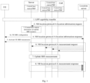
- Steps of an LPP capability transmission process triggered by a network side request are shown in Fig. 3 and include:
- Actively transmitting capability information through an LPP capability indication process includes: the UE actively reports an LPP providing capability to the network side.
- the above network side may be a base station or an LMF entity in a 5G location architecture.
- the communication base station is further configured to: receive a UE capability information message reported by the UE, and determine whether the UE supports to transmit an SRS in the idle state or the inactive state, the above UE capability information message may be an RRC message, and the above active request mode or the UE active transmission mode may be adopted; or obtain a UE capability providing message reported by the UE from the LMF entity, and determine whether the UE supports to transmit the SRS in the idle state or the inactive state, and the above UE capability providing message may be an LPP protocol message.
- the LMF entity is further configured to: receive an LPP message reported by the UE, and determine whether the UE supports to transmit the SRS in the idle state or the inactive state; and transmit the LPP message reported by the UE to the base station, such that the base station determines whether the UE supports to transmit the SRS in the idle state or the inactive state according to the LPP message.
- the LMF entity may obtain the above LPP message by adopting the active request or UE active transmission mode.
- the UE is further configured to report whether the UE supports to transmit the SRS in the idle state or inactive state through the UE capability information message or the UE capability providing message, and the active transmission mode or a transmission mode based on the network side request may be adopted by the UE.
- the UE may transmit, to the base station and the LMF entity, the capability that whether it supports to transmit the location SRS in the idle state and whether it supports to transmit the location SRS in the inactive state.
- the base station and the LMF entity may decide whether the UE needs to execute transmitting the SRS in the idle state or the inactive state according to relevant capabilities and service situations of the UE.
- the RRC protocol message is a UE capability information message
- the LPP protocol is a UE capability providing message.
- a new SRS resource is obtained by entering a connected state through a resume process when the above UE determines that it is currently in the inactive state and the condition of stopping transmitting the SRS is reached.
- the above SRS configuration information further includes information used for determining whether the condition of stopping transmitting the SRS is reached, and the UE determines whether the condition of stopping transmitting the SRS is reached according to these information.
- the new SRS resource may be obtained by entering the connected state through the resume process by default, and it may further be determined whether to obtain the new SRS resource by entering the connected state through the resume process according to the indication of the network side.
- the RRC connection release message indicated by the above communication base station further includes: connection resume indication information, configured for indicating whether the UE obtains a new SRS resource by resuming the RRC connection when the UE reaches a condition of stopping transmitting an SRS.
- the above SRS resource configuration information at least includes:
- the RRC connection release message further includes at least one piece of the following information.
- the failure of the valid duration configured for the SRS resource may be used for judging whether the condition of stopping transmitting the SRS is reached, that is, the UE determines that the condition of stopping transmitting the SRS is reached when determines the valid duration is invalid.
- the SRS configuration information contains the valid duration, the UE enables a timer when entering the idle state, and a timing length of the timer is the valid duration length. Before the timer runs out of time, the UE transmits the SRS according to the configured SRS cycle. When the timer runs out of time, the UE stops transmitting the SRS.
- the valid duration for the above configured SRS resource may be in any of the following ways:
- the base station may further indicate whether the UE in the inactive state needs to obtain new parameters by resuming the RRC connection after reaching the valid duration.
- Leaving the valid positioning area configured for the SRS resource may be used for judging whether the condition of stopping transmitting the SRS is reached, that is, when the UE determines that it leaves the valid positioning area configured for the SRS resource, and the condition of stopping transmitting the SRS is reached.
- the valid positioning area configured for the above SRS resource may be in any of the following ways:
- the UE will automatically execute an RNA update process when the UE leaves the area, so as to obtain a new configuration. If a configured area region is smaller than RNA, the base station may independently indicate whether to enter the connected state to obtain the new configuration after leaving the valid positioning area.
- Reaching the quantity of using times configured for the SRS resource may be used for judging whether the condition of stopping transmitting the SRS is reached, that is, when the UE determines that the quantity of using times configured for the SRS resource is reached, the condition of stopping transmitting the SRS is reached.
- the determining that the condition of stopping transmitting the SRS is reached includes: determining that the condition of stopping transmitting the SRS is reached when the UE determines that any one of the following conditions is met: the valid duration being invalid, leaving the valid positioning area or the SRS resource being used up to the quantity of using times.
- the base station may further indicate whether the UE in the inactive state needs to obtain new parameters by resuming the RRC connection after reaching the condition of stopping transmitting the SRS.
- the new SRS resource is obtained by entering the connected state through the resume process.
- the UE If the configuration information contains the valid duration, the UE enables the timer when entering the inactive state, and the timing length of the timer is the valid duration length. Before the timer runs out of time, the UE transmits the SRS according to the configured SRS cycle. When the timer runs out of time, the UE stops transmitting the SRS. The UE may enter the connected state through the resume process, and if the base station has a new SRS resource to be configured for the UE, the UE may use the new SRS resource to transmit the SRS subsequently.
- the UE transmits the SRS according to the SRS configuration within the valid positioning area.
- the UE when moving beyond the valid positioning area, stops transmitting the SRS.
- the UE may enter the connected state through the resume process (an RRC connection resume process), and if the base station has a new SRS resource to be configured for the UE, the UE may use the new SRS resource to transmit the SRS subsequently.
- the configuration information contains the quantity of transmitting times
- a counter is enabled when the UE enters the idle state, and the counter will be increased by 1 each time the SRS is transmitted.
- the UE will not transmit the SRS any more.
- the UE may enter the connected state through the resume process, and if the base station has a new SRS resource to be configured for the UE, the UE may use the new SRS resource to transmit the SRS subsequently.
- the base station on the network side measures the SRS of the UE according to the SRS configuration information transmitted to the UE, and reports the measurement result to the LMF entity.
- Fig. 5 is a flow of uplink signal location in an idle state, which includes the following steps.
- UE actively reports, to a base station, supporting to transmit a location SRS in an idle state through a UE capability information message.
- S503 when the base station may determine that the UE currently only has a location service, and determine that a location method of the UE indicated by an LMF entity is an uplink signal location method according to the UE capability information message and a service situation of the UE, S503 is executed; and if the location method of the UE indicated by the LMF entity is not the uplink signal location method, an existing flow is executed, such as a downlink signal location method of a wireless mobile system, which will not be repeated here.
- the base station transmits SRS resource configuration information to the LMF entity, the LMF entity selects one or more base stations that need to perform UE uplink SRS measurement according to a current location of the UE, and transmits the SRS configuration information of the UE to the one or more base stations.
- the SRS resource configuration information includes: a physical resource of an SRS, a cycle and an offset of the SRS; and/or
- a communication base station transmits an RRC connection release message carrying the SRS resource configuration information to the UE.
- the SRS resource configuration information carries a sounding reference signal (SRS) resource that is configured for the UE and used for location in an idle state or an inactive state.
- SRS sounding reference signal
- the UE after receiving the RRC connection release message, the UE enters the idle state and transmits an SRS on a specified SRS resource according to the SRS resource configuration information carried in the RRC connection release message.
- step S506 the UE determines whether the condition of stopping transmitting the SRS is reached, if yes, an end step is executed, and otherwise step S505 is returned.
- the condition of stopping transmitting the SRS includes: determining that the condition of stopping transmitting the SRS is reached when the UE determines that any one of the following conditions is met: the valid duration being invalid, leaving the valid positioning area or the SRS resource being used up to the quantity of using times.
- the SRS configuration information contains the valid duration, the UE enables a timer when entering the idle state, and a timing length of the timer is the valid duration length. Before the timer runs out of time, the UE transmits the SRS according to the configured SRS cycle. When the timer runs out of time, the UE stops transmitting the SRS.
- the UE If the configuration information contains the valid positioning area, the UE transmits the SRS according to the SRS configuration information within the valid positioning area. The UE, when moving beyond the valid positioning area, stops transmitting the SRS.
- the UE If the configuration information contains the quantity of transmitting times, the UE enables a counter when entering the idle state, and the counter will be increased by 1 each time the SRS is transmitted. When the count of counter is equal to the quantity of transmitting times in the configuration information, the UE will not transmit the SRS any more.
- the UE stops transmitting the SRS when any one of the situations reaches the condition of stopping transmitting.
- the measurement base station receives the SRS resource transmitted by the LMF entity and performs an SRS measurement on the UE according to the SRS resource, and the LMF entity transmits information of the measurement base station to a base station to which a service cell where the UE is located belongs.
- Fig. 6 is a flow of uplink signal location in an inactive state, which includes the following steps.
- UE actively reports, to a base station, supporting to transmit a location SRS in an inactive state through a UE capability information message.
- S603 when the base station may determine that the UE currently only has a location service, and determine that a location method of the UE indicated by an LMF entity is an uplink signal location method according to the UE capability information message and the service situation of the UE, S603 is executed.
- the location method indicated by the LMF entity is not the uplink signal location method
- an existing flow is executed, such as a downlink signal location method of a wireless mobile system, which will not be repeated here.
- the base station transmits SRS resource configuration information to the LMF entity, the LMF entity selects one or more base stations that need to execute UE uplink SRS location signal measurement according to a current location of the UE, and transmits the SRS resource configuration information of the UE to the one or more base stations.
- the SRS resource configuration information includes a physical resource of an SRS, a cycle and an offset of the SRS; and/or
- a communication base station transmits an RRC connection release message carrying the SRS resource configuration information to the UE.
- the SRS resource configuration information carries a sounding reference signal (SRS) resource that is configured for the UE and used for location in an idle state or an inactive state.
- SRS sounding reference signal
- the UE after receiving the RRC connection release message, the UE enters the idle state and transmits an SRS on a specified SRS resource according to the SRS resource configuration information carried in the RRC connection release message.
- the UE determines whether the condition of stopping transmitting the SRS is reached, if yes, S607 is executed, and otherwise S605 is returned.
- the condition of stopping transmitting the SRS includes: determining that the condition of stopping transmitting the SRS is reached when it is determined that any one of the following conditions is met: the valid duration being invalid, leaving the valid positioning area or the SRS resource being used up to the quantity of using times.
- the UE if the configuration information contains the valid duration, the UE enables the timer when entering the inactive state, and the timing length of the timer is the valid duration length. Before the timer runs out of time, the UE transmits the SRS according to the configured SRS cycle. When the timer runs out of time, the UE stops transmitting the SRS. The UE may enter the connected state through the resume process, and if the base station has a new SRS resource to be configured for the UE, the UE may use the new SRS resource to transmit the SRS subsequently.
- the UE transmits the SRS according to the SRS configuration within the valid positioning area.
- the UE when moving beyond the valid positioning area, stops transmitting the SRS.
- the UE may enter the connected state through the resume process (an RRC connection resume process), and if the base station has a new SRS resource to be configured for the UE, the UE may use the new SRS resource to transmit the SRS subsequently.
- a counter is enabled when the UE enters the idle state, and the counter will be increased by 1 each time the SRS is transmitted. When the count of the counter is equal to the quantity of transmitting times in the configuration information, the UE will not transmit the SRS any more.
- step S607 determining whether to obtain a new SRS resource through a resume process, if yes, step S603 is executed, and if not, it ends.
- the measurement base station receives the SRS resource transmitted by the LMF entity and performs an SRS measurement on the UE according to the SRS resource, and the LMF entity transmits information of the measurement base station to a base station to which a service cell where the UE is located belongs.
- the embodiments of the present application provide an uplink signal location method, applied to a communication base station, as shown in Fig. 7 , including the following steps.
- the RRC connection release message includes SRS resource configuration information, and the SRS resource configuration information carries an SRS resource that is configured for the UE and used for location in an idle state or an inactive state.
- the method further includes: transmitting the SRS resource to the LMF entity, such that the LMF entity transmits the SRS resource to a measurement base station, and the measurement base station performs an SRS measurement according to the SRS resource.
- the RRC connection release message further includes at least one piece of the following information:
- the RRC connection release message further includes: connection resume indication information, configured for indicating whether the UE obtains a new SRS resource for location by resuming the RRC connection when the UE is in the inactive state and reaches a condition of stopping transmitting an SRS.
- the method further includes:
- the SRS resource configuration information includes a physical resource of an SRS, a cycle and an offset of the SRS; and/or
- the embodiments of the present application further provide an uplink signal location method, applied to UE, as shown in Fig. 8 , including:
- the RRC connection release message further includes at least one piece of the following information:
- the method further includes: stopping transmitting the SRS by using the SRS resource and keeping in the idle state when the UE is currently in the idle state and determines that a condition of stopping transmitting the SRS is reached.
- the method further includes: obtaining a new SRS resource for location by entering a connected state through a resume process when the UE is currently in the inactive state and determines that a condition of stopping transmitting the SRS is reached.
- the method further includes: when the UE determines that the condition of stopping transmitting the SRS is reached, determining whether to obtain a new SRS resource for location by entering a connected state through a resume process according to a connection resume indication in the RRC connection release message.
- the determining that the condition of stopping transmitting the SRS is reached includes: determining that the condition of stopping transmitting the SRS is reached when the UE determines that any one of the following conditions is met: the valid duration being invalid, leaving the valid positioning area or the SRS resource being used up to the quantity of using times.
- the method further includes: reporting whether the UE supports to transmit the SRS in the idle state or the inactive state through a UE capability information message or a UE capability providing message.
- the SRS resource configuration information includes a physical resource of an SRS, a cycle and an offset of the SRS; and/or
- the embodiments the present application further provide an uplink signal location method, applied to a measurement base station, as shown in Fig. 9 , including:
- the method further includes: receiving at least one piece of the following information that is configured for the UE by the communication base station and transmitted by the LMF entity:
- the uplink signal location method on the communication base station side provided by the embodiments of the present application belongs to the same inventive concept as the communication base station in embodiment 1 of the present application.
- Various implementations applied to uplink signal location of the communication base station in the system provided by the above embodiments may be applied to the uplink signal location method applied to the communication base station in the embodiments, which will not be repeated here.
- the uplink signal location method on the UE side provided by the embodiments of the present application belongs to the same inventive concept as the UE in embodiment 1 of the present application.
- Various implementations applied to uplink signal location of the UE in the system provided by the above embodiments may be applied to the uplink signal location method applied to the UE in the embodiments, which will not be repeated here.
- the uplink signal location method on the measurement base station side provided by the embodiments of the present application belongs to the same inventive concept as the measurement base station in embodiment 1 of the present application.
- Various implementations applied to uplink signal location of the measurement base station in the system provided by the above embodiments may be applied to the uplink signal location method applied to the measurement base station in the embodiments, which will not be repeated here.
- the embodiments of the present application provide a communication base station for uplink signal location, as shown in Fig. 10 , includes: a memory 1001, a processor 1002, a transceiver 1003 and a bus interface 1004.
- the processor 1002 is responsible for managing a bus architecture and general processing, and the memory 1001 may store data used when the processor 1002 executes operations.
- the transceiver 1003 is configured to receive and transmit data under the control of the processor 1002.
- the bus architecture may include interconnected buses of any quantity and bridges of any quantity, which link various circuits of one or more processors represented by the processor 1002 and various circuits of memories represented by the memory 1001.
- the bus architecture may also link various other circuits such as peripheral devices, voltage regulators, and power management circuits, which are well known in the art, and therefore are not further described herein.
- the bus interface provides an interface.
- the processor 1002 is responsible for managing the bus architecture and general processing, and the memory 1001 may store data used when the processor 1002 executes operations.
- a flow disclosed in the embodiments of the present application may be applied to the processor 1002 or implemented by the processor 1002. During an implementation process, all steps of a signal processing flow may be completed by an integrated logic circuit of hardware or an instruction in the form of software in the processor 1002.
- the processor 1002 may be a general-purpose processor, a digital signal processor, an application specific integrated circuit, a field programmable gate array or other programmable logic devices, a discrete gate or a transistor logic device, or a discrete hardware component, and may implement or execute methods, steps and logic block diagrams disclosed in the embodiments of the present application.
- the general-purpose processor may be a microprocessor, or any conventional processor, etc.
- the steps of the method disclosed in conjunction with the embodiments of the present application may be directly embodied to be executed and completed by a hardware processor, or may be executed and completed through a combination of hardware and software modules in the processor.
- the software module may be located in a mature storage medium in the art, such as a random access memory, a flash memory, a read-only memory, a programmable read-only memory, an electrically erasable programmable memory, and a register.
- the storage medium is located in the memory 1001, and the processor 1002 reads information in the memory 1001, and completes the steps of the signal processing flow in combination with its hardware.
- the processor 1002 is configured to read computer programs in the memory 1001 and execute:
- the processor is further configured to: transmit the SRS resource to the LMF entity, such that the LMF entity transmits the SRS resource to a measurement base station, and the measurement base station performs an SRS measurement according to the SRS resource.
- the RRC connection release message further includes at least one piece of the following information:
- the RRC connection release message further includes: connection resume indication information, configured for indicating whether the UE obtains a new SRS resource for location by resuming the RRC connection when the UE is in the inactive state and reaches a condition of stopping transmitting an SRS.
- the processor before transmitting the RRC connection release message to the UE, the processor is further configured to:
- the SRS resource configuration information includes a physical resource of an SRS, a cycle and an offset of the SRS; and/or
- the embodiments of the present application provide a UE for uplink signal location, as shown in Fig. 11 , includes: a memory 1101, a processor 1102, a transceiver 1103 and a bus interface 1104.
- the processor 1102 is responsible for managing a bus architecture and general processing, and the memory 1101 may store data used when the processor 1102 executes operations.
- the transceiver 1103 is configured to receive and transmit data under the control of the processor 1102.
- the bus architecture may include interconnected buses of any quantity and bridges of any quantity, which specifically link various circuits of one or more processors represented by the processor 1102 and various circuits of memories represented by the memory 1101.
- the bus architecture may also link various other circuits such as peripheral devices, voltage regulators, and power management circuits, which are well known in the art, and therefore are not further described herein.
- the bus interface provides an interface.
- the processor 1102 is responsible for managing the bus architecture and general processing, and the memory 1101 may store data used when the processor 1102 executes operations.
- a flow disclosed in the embodiments of the present application may be applied to the processor 1102 or implemented by the processor 1102. During an implementation process, all steps of a signal processing flow may be completed by an integrated logic circuit of hardware or an instruction in the form of software in the processor 1102.
- the processor 1102 may be a general-purpose processor, a digital signal processor, an application specific integrated circuit, a field programmable gate array or other programmable logic devices, a discrete gate or a transistor logic device, or a discrete hardware component, and may implement or execute methods, steps and logic block diagrams disclosed in the embodiments of the present application.
- the general-purpose processor may be a microprocessor, or any conventional processor, etc.
- the steps of the method disclosed in conjunction with the embodiments of the present application may be directly embodied to be executed and completed by a hardware processor, or may be executed and completed through a combination of hardware and software modules in the processor.
- the software module may be located in a mature storage medium in the art, such as a random access memory, a flash memory, a read-only memory, a programmable read-only memory, an electrically erasable programmable memory, and a register.
- the storage medium is located in the memory 1101, and the processor 1102 reads information in the memory 1101, and completes the steps of the signal processing flow in combination with its hardware.
- the processor 1102 is configured to read computer programs in the memory 1101 and execute:
- the RRC connection release message further includes at least one piece of the following information:
- the processor is further configured to: stop transmitting the SRS by using the SRS resource and keep in the idle state when the UE is currently in the idle state and determines that a condition of stopping transmitting the SRS is reached.
- the processor is further configured to: obtain a new SRS resource for location by entering a connected state through a resume process when the UE is currently in the inactive state and determines that a condition of stopping transmitting the SRS is reached.
- the determining, by the processor, that the condition of stopping transmitting the SRS is reached includes: when the UE determines that a condition of stopping transmitting the SRS is reached, determining whether to obtain a new SRS resource for location by entering a connected state through a resume process according to a connection resume indication in the RRC connection release message.
- the determining, by the processor, that the condition of stopping transmitting the SRS is reached includes: determining that a condition of stopping transmitting the SRS is reached when the UE determines that any one of the following conditions is met: the valid duration being invalid, leaving the valid positioning area or the SRS resource being used up to the quantity of using times.
- the determining, by the processor, that the condition of stopping transmitting the SRS is reached includes: reporting whether the UE supports to transmit the SRS in the idle state or the inactive state through a UE capability information message or a UE capability providing message.
- the SRS resource configuration information includes a physical resource of an SRS, a cycle and an offset of the SRS; and/or
- the embodiments of the present application provide a measurement base station for uplink signal location, as shown in Fig. 12 , includes: a memory 1201, a processor 1202, a transceiver 1203 and a bus interface 1204.
- the processor 1202 is responsible for managing a bus architecture and general processing, and the memory 1201 may store data used when the processor 1202 executes operations.
- the transceiver 1203 is configured to receive and transmit data in the control of the processor 1202.
- the bus architecture may include interconnected buses of any quantity and bridges of any quantity, which specifically link various circuits of one or more processors represented by the processor 1202 and various circuits of memories represented by the memory 1201.
- the bus architecture may also link various other circuits such as peripheral devices, voltage regulators, and power management circuits, which are well known in the art, and therefore are not further described herein.
- the bus interface provides an interface.
- the processor 1202 is responsible for managing the bus architecture and general processing, and the memory 1201 may store data used when the processor 1202 executes operations.
- a flow disclosed in the embodiments of the present application may be applied to the processor 1202 or implemented by the processor 1202. During an implementation process, all steps of a signal processing flow may be completed by an integrated logic circuit of hardware or an instruction in the form of software in the processor 1202.
- the processor 1202 may be a general-purpose processor, a digital signal processor, an application specific integrated circuit, a field programmable gate array or other programmable logic devices, a discrete gate or a transistor logic device, or a discrete hardware component, and may implement or execute methods, steps and logic block diagrams disclosed in the embodiments of the present application.
- the general-purpose processor may be a microprocessor, or any conventional processor, etc.
- the steps of the method disclosed in conjunction with the embodiments of the present application may be directly embodied to be executed and completed by a hardware processor, or may be executed and completed through a combination of hardware and software modules in the processor.
- the software module may be located in a mature storage medium in the art, such as a random access memory, a flash memory, a read-only memory, a programmable read-only memory, an electrically erasable programmable memory, and a register.
- the storage medium is located in the memory 1201, and the processor 1202 reads information in the memory 1201, and completes the steps of the signal processing flow in combination with its hardware.
- the processor 1202 is configured to read computer programs in the memory 1201 and execute:
- the processor 1202 is further configured to: receive at least one piece of the following information that is configured for the UE by the communication base station and transmitted by the LMF entity:
- the communication base station for uplink signal location provided by the embodiments of the present application belongs to the same inventive concept as the communication base station in embodiment 1 of the present application.
- Various implementations applied to uplink signal location of the communication base station in the system provided by the above embodiments may be applied to the communication base station for uplink signal location in the embodiments, which will not be repeated here.
- the UE for uplink signal location provided by the embodiments of the present application belongs to the same inventive concept as the UE in embodiment 1 of the present application.
- Various implementations applied to the UE for uplink signal location in the system provided by the above embodiments may be applied to the uplink signal location UE in the embodiments, which will not be repeated here.
- the measurement base station for uplink signal location provided by the embodiments of the present application belongs to the same inventive concept as the measurement base station in embodiment 1 of the present application.
- Various implementations applied to uplink signal location of the measurement base station in the system provided by the above embodiments may be applied to the measurement base station for uplink signal location in the embodiments, which will not be repeated here.
- a communication base station for uplink signal location provided by the present application, as shown in Fig. 13 , includes:
- the transmitting unit is further configured to: transmit the SRS resource to the LMF entity, such that the LMF entity transmits the SRS resource to a measurement base station, and the measurement base station performs an SRS measurement according to the SRS resource.
- the RRC connection release message further includes at least one piece of the following information:
- the RRC connection release message further includes: connection resume indication information, configured for indicating whether the UE obtains a new SRS resource for location by resuming the RRC connection when the UE is in the inactive state and reaches a condition of stopping transmitting an SRS.
- the determining unit is further configured to: receive a UE capability information message reported by the UE, and determine whether the UE supports to transmit an SRS in the idle state or the inactive state; or obtain a UE capability providing message reported by the UE from the LMF entity, and determine whether the UE supports to transmit the SRS in the idle state or the inactive state.
- the SRS resource configuration information includes a physical resource of an SRS, a cycle and an offset of the SRS; and/or
- a UE for uplink signal location provided by the present application, as shown in Fig. 14 , includes:
- the RRC connection release message further includes at least one piece of the following information:
- the RRC connection releasing unit is further configured to: stop transmitting the SRS by using the SRS resource and keep in the idle state when the UE is currently in the idle state and determines that a condition of stopping transmitting the SRS is reached.
- the RRC connection releasing unit is further configured to: obtain a new SRS resource for location by entering a connected state through a resume process when the UE is currently in the inactive state and determines that a condition of stopping transmitting the SRS is reached.
- the RRC connection releasing unit is further configured to: determine, when the UE determines that a condition of stopping transmitting the SRS is reached, whether to obtain a new SRS resource for location by entering a connected state through a resume process according to a connection resume indication in the RRC connection release message.
- the determining, by the RRC connection releasing unit, that the condition of stopping transmitting the SRS is reached includes: determining that the condition of stopping transmitting the SRS is reached when the UE determines that any one of the following conditions is met: the valid duration being invalid, leaving the valid positioning area or the SRS resource being used up to the quantity of using times.
- the RRC connection releasing unit is further configured to: report whether the UE supports to transmit the SRS in the idle state or the inactive state through a UE capability information message or a UE capability providing message.
- the SRS resource configuration information includes a physical resource of an SRS, a cycle and an offset of the SRS; and/or
- a measurement base station for uplink signal location provided by the present application, as shown in Fig. 15 , includes:
- the SRS resource receiving unit 1501 is further configured to: receive at least one piece of the following information that is configured for the UE by the communication base station and transmitted by the LMF entity:
- the communication base station for uplink signal location provided by the embodiment of the present application belongs to the same inventive concept as the communication base station in embodiment 1 of the present application.
- Various implementations applied to the communication base station for uplink signal location in the system provided by the above embodiments may be applied to the communication base station for uplink signal location in this embodiment, which will not be repeated here.
- the UE for uplink signal location provided by the embodiment of the present application belongs to the same inventive concept as the UE in embodiment 1 of the present application.
- Various implementations applied to the UE for uplink signal location in the system provided by the above embodiments may be applied to the UE for uplink signal location in this embodiment, which will not be repeated here.
- the measurement base station for uplink signal location provided by the embodiments of the present application belongs to the same inventive concept as the measurement base station in embodiment 1 of the present application.
- Various implementations applied to the measurement base station for uplink signal location in the system provided by the above embodiments may be applied to the measurement base station for uplink signal location in this embodiment, which will not be repeated here.
- the embodiments of the present application further provide a computer program medium, the computer program medium stores computer programs, and the computer programs, when executed by a processor, implements steps of the uplink signal location method applied to the communication base station provided by embodiment 2.
- the present application further provides a computer program medium, the computer program medium stores computer programs, and the computer programs, when executed by a processor, implements steps of the uplink signal location method applied to the UE provided by embodiment 2.
- the embodiments of the present application further provide a computer program medium, the computer program medium stores computer programs, and the computer programs, when executed by a processor, implements steps of the uplink signal location method applied to the measurement base station provided by embodiment 2.
- the disclosed systems, apparatuses and methods may be implemented in other ways.
- the apparatus embodiment described above is only illustrative.
- the division of the above modules is only a logical function division.
- there may be other division modes for example, a plurality of modules or components may be combined or integrated into another system, or some features may be ignored or not executed.
- the mutual coupling or direct coupling or communication connection shown or discussed may be indirect coupling or communication connection through some interfaces, apparatuses or modules, and may be electrical, mechanical or other forms.
- modules described as separate components may or may not be physically separated, and the components displayed as modules may or may not be physical modules, that is, they may be located in one place, or may be distributed to a plurality of network modules. Some or all of the modules can be selected according to actual needs to achieve the purpose of the solution of the embodiments.
- each functional module in each embodiment of the present application may be integrated into one processing module, or each module may physically exist separately, or two or more modules may be integrated into one module.
- the above integrated module may be implemented in the form of hardware or a software functional module. If the integrated module is implemented in the form of software functional modules and is sold or used as an independent product, the integrated module may be stored in a computer readable storage medium.
- the computer program product includes one or more computer instructions.
- the computer may be a general-purpose computer, a special-purpose computer, a computer network or other programmable apparatuses.
- the computer instructions may be stored in a computer readable storage medium, or transmitted from one computer readable storage medium to another computer readable storage medium, for example, the computer instructions may be transmitted from a website, computer, server or data center through wired modes (such as a coaxial cable, an optical fiber and a digital subscriber line (DSL)) or wireless modes (such as infrared, wireless and microwave) to another website, computer, server or data center.
- wired modes such as a coaxial cable, an optical fiber and a digital subscriber line (DSL)
- wireless modes such as infrared, wireless and microwave
- the computer readable storage medium may be any available medium that can be stored by the computer or a data storage device including a server, a data center and the like integrated by one or more available media.
- the available media may be magnetic media (such as a floppy disk, a hard disk and a magnetic tape), optical media (such as DVD) or a semiconductor medium (such as a solid state disk (SSD)) and the like.
- the embodiments of the present application may be provided as methods, systems, or computer program products. Therefore, the present application may take the form of a full hardware embodiment, a full software embodiment, or an embodiment combining software and hardware. Besides, the present application may adopt the form of a computer program product implemented on one or more computer available storage media (including but not limited to a disk memory, a CD-ROM, an optical memory and the like) containing computer available program codes.
- a computer available storage media including but not limited to a disk memory, a CD-ROM, an optical memory and the like
- each flow and/or block in the flow charts and/or block diagrams and the combination of flows and/or blocks in the flow charts and/or block diagrams can be implemented by computer program instructions.
- These computer program instructions can be provided to processors of a general-purpose computer, a special-purpose computer, an embedded processor or other programmable data processing devices to generate a machine, so that instructions executed by processors of a computer or other programmable data processing devices generate an apparatus for implementing the functions specified in one or more flows of the flow charts and/or one or more blocks of the block diagrams.
- These computer program instructions may also be stored in a computer-readable memory capable of guiding a computer or other programmable data processing devices to work in a specific manner, so that instructions stored in the computer-readable memory generate a manufactured product including an instruction apparatus, and the instruction apparatus implements the functions specified in one or more flows of the flow charts and/or one or more blocks of the block diagrams.
- These computer program instructions may also be loaded on a computer or other programmable data processing devices, so that a series of operation steps are executed on the computer or other programmable devices to produce computer-implemented processing, and thus, the instructions executed on the computer or other programmable devices provide steps for implementing the functions specified in one or more flows of the flow charts and/or one or more blocks of the block diagrams.
Landscapes
- Engineering & Computer Science (AREA)
- Signal Processing (AREA)
- Computer Networks & Wireless Communication (AREA)
- Mobile Radio Communication Systems (AREA)
- Position Fixing By Use Of Radio Waves (AREA)
Applications Claiming Priority (2)
| Application Number | Priority Date | Filing Date | Title |
|---|---|---|---|
| CN202010712303.1A CN113973260B (zh) | 2020-07-22 | 2020-07-22 | 上行信号定位的方法、通信基站和测量基站及ue |
| PCT/CN2021/107305 WO2022017369A1 (zh) | 2020-07-22 | 2021-07-20 | 上行信号定位的方法、通信基站和测量基站及ue |
Publications (2)
| Publication Number | Publication Date |
|---|---|
| EP4187964A1 true EP4187964A1 (de) | 2023-05-31 |
| EP4187964A4 EP4187964A4 (de) | 2024-01-31 |
Family
ID=79584953
Family Applications (1)
| Application Number | Title | Priority Date | Filing Date |
|---|---|---|---|
| EP21846117.6A Pending EP4187964A4 (de) | 2020-07-22 | 2021-07-20 | Uplink-signalortungsverfahren, kommunikationsbasisstation, messbasisstation und benutzergerät |
Country Status (4)
| Country | Link |
|---|---|
| US (1) | US12526877B2 (de) |
| EP (1) | EP4187964A4 (de) |
| CN (1) | CN113973260B (de) |
| WO (1) | WO2022017369A1 (de) |
Cited By (1)
| Publication number | Priority date | Publication date | Assignee | Title |
|---|---|---|---|---|
| US20220120842A1 (en) * | 2020-10-15 | 2022-04-21 | Qualcomm Incorporated | Method and apparatus for location of a user equipment in an inactive state |
Families Citing this family (18)
| Publication number | Priority date | Publication date | Assignee | Title |
|---|---|---|---|---|
| WO2022067505A1 (zh) * | 2020-09-29 | 2022-04-07 | 华为技术有限公司 | 通信方法及装置 |
| KR20230121066A (ko) * | 2020-12-24 | 2023-08-17 | 퀄컴 인코포레이티드 | 포지셔닝을 위한 무선 액세스 네트워크 통지 영역의 구성 |
| WO2022141099A1 (zh) * | 2020-12-29 | 2022-07-07 | 华为技术有限公司 | 一种上行定位方法及通信装置 |
| CN115150746A (zh) * | 2021-03-31 | 2022-10-04 | 华为技术有限公司 | 一种寻呼方法和装置 |
| US20240349224A1 (en) * | 2021-08-02 | 2024-10-17 | Beijing Xiaomi Mobile Software Co., Ltd. | Positioning measurement method, communication device, and storage medium |
| KR102517313B1 (ko) * | 2021-10-05 | 2023-04-03 | 주식회사 블랙핀 | 무선 이동 통신 시스템에서 페이징 메시지를 이용해서 인액티브 상태에서 사운딩기준신호 전송을 중지하는 방법 및 장치 |
| CN116634352A (zh) * | 2022-02-11 | 2023-08-22 | 华为技术有限公司 | 通信方法以及通信装置 |
| CN117204074A (zh) * | 2022-03-30 | 2023-12-08 | 北京小米移动软件有限公司 | 上行定位参考信号的配置方法、装置、设备及存储介质 |
| CN117395796A (zh) * | 2022-06-30 | 2024-01-12 | 大唐移动通信设备有限公司 | 定位资源配置方法、装置、终端、网络设备及功能网元 |
| WO2024000499A1 (en) * | 2022-06-30 | 2024-01-04 | Zte Corporation | Power saving positioning for wireless communications |
| CN117545065A (zh) * | 2022-07-27 | 2024-02-09 | 大唐移动通信设备有限公司 | 信息传输方法、装置及存储介质 |
| WO2024031234A1 (en) * | 2022-08-08 | 2024-02-15 | Lenovo (Beijing) Limited | Methods and apparatuses for user equipment positioning |
| CN120380727A (zh) * | 2023-01-05 | 2025-07-25 | 联想(北京)有限公司 | 用于上行链路定位的方法及设备 |
| KR20240126286A (ko) * | 2023-02-13 | 2024-08-20 | 삼성전자주식회사 | 무선 통신 시스템에서 rrc inactive 상태인 단말의 포지셔닝 서비스를 지원하기 위한 방법 및 장치 |
| CN118540719A (zh) * | 2023-02-14 | 2024-08-23 | 维沃移动通信有限公司 | 配置更新方法、配置更新装置、终端及网络侧设备 |
| WO2024197609A1 (en) * | 2023-03-28 | 2024-10-03 | Nec Corporation | Devices and methods for communication |
| CN116830676A (zh) * | 2023-04-04 | 2023-09-29 | 北京小米移动软件有限公司 | 信息处理方法及装置、通信设备及存储介质 |
| WO2025091443A1 (en) * | 2023-11-03 | 2025-05-08 | Nokia Shanghai Bell Co., Ltd. | Sounding reference signal resource release |
Family Cites Families (16)
| Publication number | Priority date | Publication date | Assignee | Title |
|---|---|---|---|---|
| CN113259053A (zh) * | 2015-01-29 | 2021-08-13 | 北京三星通信技术研究有限公司 | 上行控制信号的发送方法及装置 |
| CN105282778A (zh) * | 2015-06-01 | 2016-01-27 | 南京纳凯永馨信息科技有限公司 | 一种lte终端的定位方法及模拟基站 |
| CN106535131B (zh) * | 2016-12-05 | 2019-07-09 | 四川猎鹰科技有限公司 | 采用第三方定位装置对wcdma终端进行定位的方法 |
| CN108271125B (zh) * | 2017-01-04 | 2022-01-28 | 中兴通讯股份有限公司 | 数据发送、数据接收方法及装置 |
| CN110637495B (zh) | 2017-05-04 | 2023-11-28 | Lg 电子株式会社 | 无线通信系统中通过波束发送和接收信号的方法及用于该方法的装置 |
| EP3678449B1 (de) * | 2017-09-21 | 2022-06-01 | Huawei Technologies Co., Ltd. | Verbindungsverwaltungsverfahren und benutzervorrichtung |
| CN110022523B (zh) * | 2018-01-05 | 2022-04-12 | 华为技术有限公司 | 用于终端设备定位的方法、装置及系统 |
| US11503634B2 (en) * | 2018-02-14 | 2022-11-15 | Lg Electronics Inc. | Method and apparatus for supporting RACH-less mobility with pre-allocated beams in wireless communication system |
| CN110650492B (zh) | 2018-06-27 | 2021-06-18 | 维沃移动通信有限公司 | 一种测量方法、终端和网络侧设备 |
| CN110784889B (zh) | 2018-07-31 | 2023-05-09 | 中国移动通信有限公司研究院 | 测量方法、测量配置方法、装置、终端及网络侧设备 |
| CN111278116B (zh) * | 2018-12-28 | 2022-09-16 | 维沃移动通信有限公司 | 上行信号发送方法及装置 |
| CN111343567A (zh) * | 2019-01-04 | 2020-06-26 | 维沃移动通信有限公司 | 非连接态上行定位方法和设备 |
| US11470669B2 (en) * | 2019-03-28 | 2022-10-11 | Lg Electronics Inc. | Method of operating transmitting UE in relation to RLF reporting in wireless communication system |
| WO2021012114A1 (zh) * | 2019-07-19 | 2021-01-28 | 小米通讯技术有限公司 | 设备内共存干扰指示方法、接收方法和装置 |
| WO2021046695A1 (zh) | 2019-09-09 | 2021-03-18 | 北京小米移动软件有限公司 | 测量处理方法及装置 |
| WO2022067505A1 (zh) * | 2020-09-29 | 2022-04-07 | 华为技术有限公司 | 通信方法及装置 |
-
2020
- 2020-07-22 CN CN202010712303.1A patent/CN113973260B/zh active Active
-
2021
- 2021-07-20 US US18/017,086 patent/US12526877B2/en active Active
- 2021-07-20 EP EP21846117.6A patent/EP4187964A4/de active Pending
- 2021-07-20 WO PCT/CN2021/107305 patent/WO2022017369A1/zh not_active Ceased
Cited By (2)
| Publication number | Priority date | Publication date | Assignee | Title |
|---|---|---|---|---|
| US20220120842A1 (en) * | 2020-10-15 | 2022-04-21 | Qualcomm Incorporated | Method and apparatus for location of a user equipment in an inactive state |
| US12392858B2 (en) * | 2020-10-15 | 2025-08-19 | Qualcomm Incorporated | Method and apparatus for location of a user equipment in an inactive state |
Also Published As
| Publication number | Publication date |
|---|---|
| US20230300942A1 (en) | 2023-09-21 |
| US12526877B2 (en) | 2026-01-13 |
| WO2022017369A1 (zh) | 2022-01-27 |
| CN113973260B (zh) | 2023-08-01 |
| EP4187964A4 (de) | 2024-01-31 |
| CN113973260A (zh) | 2022-01-25 |
Similar Documents
| Publication | Publication Date | Title |
|---|---|---|
| US12526877B2 (en) | Uplink signal location method, communication base station, measurement base station, and UE | |
| US12004105B2 (en) | Time synchronization method and apparatus | |
| CN112188541B (zh) | 信号传输方法及装置 | |
| CN112838916B (zh) | 信息传输方法及装置 | |
| EP3993451A1 (de) | Verfahren zur positionierung und kommunikationsgerät | |
| CN111954147A (zh) | 信号传输、信号测量上报、定位方法及装置 | |
| CN110972054B (zh) | 定位方法及装置 | |
| US20240276271A1 (en) | Expedited measurement reporting (xmr) | |
| WO2019228425A1 (zh) | 一种定位方法及装置 | |
| US20250310817A1 (en) | Measurement result reporting method and apparatus, and device and storage medium | |
| CN113518395A (zh) | 一种信息传输的方法和装置 | |
| WO2021026842A1 (zh) | 无线通信方法、网络设备和终端设备 | |
| CN111194072B (zh) | 多波束场景下监听寻呼的方法及装置 | |
| US20230039155A1 (en) | Positioning method, positioning apparatus, and device | |
| WO2023227020A1 (zh) | 一种信息处理方法、装置及可读存储介质 | |
| WO2023078218A1 (zh) | 定位方法、用户设备及网络设备 | |
| CN116074950A (zh) | 定位方法、装置及相关设备 | |
| CN112332969B (zh) | 参考信号的传输方法、终端及网络设备 | |
| CN115119139A (zh) | 定位方法、装置、终端及存储介质 | |
| WO2021159262A1 (zh) | 定时提前量的阈值调整方法及装置 | |
| CN116210293B (zh) | 定位测量报告 | |
| CN115243366A (zh) | 定位方法、装置、网络设备、基站及存储介质 | |
| CN118803943A (zh) | 位置系统信息监听方法和设备 | |
| CN116506941A (zh) | Dl-tdoa定位的方法及装置 |
Legal Events
| Date | Code | Title | Description |
|---|---|---|---|
| STAA | Information on the status of an ep patent application or granted ep patent |
Free format text: STATUS: THE INTERNATIONAL PUBLICATION HAS BEEN MADE |
|
| PUAI | Public reference made under article 153(3) epc to a published international application that has entered the european phase |
Free format text: ORIGINAL CODE: 0009012 |
|
| STAA | Information on the status of an ep patent application or granted ep patent |
Free format text: STATUS: REQUEST FOR EXAMINATION WAS MADE |
|
| 17P | Request for examination filed |
Effective date: 20230221 |
|
| AK | Designated contracting states |
Kind code of ref document: A1 Designated state(s): AL AT BE BG CH CY CZ DE DK EE ES FI FR GB GR HR HU IE IS IT LI LT LU LV MC MK MT NL NO PL PT RO RS SE SI SK SM TR |
|
| DAV | Request for validation of the european patent (deleted) | ||
| DAX | Request for extension of the european patent (deleted) | ||
| REG | Reference to a national code |
Ref country code: DE Ref legal event code: R079 Free format text: PREVIOUS MAIN CLASS: H04W0024080000 Ipc: H04L0005000000 |
|
| A4 | Supplementary search report drawn up and despatched |
Effective date: 20240105 |
|
| RIC1 | Information provided on ipc code assigned before grant |
Ipc: H04W 8/24 20090101ALN20231222BHEP Ipc: H04W 76/30 20180101ALI20231222BHEP Ipc: H04W 76/27 20180101ALI20231222BHEP Ipc: H04W 64/00 20090101ALI20231222BHEP Ipc: H04W 4/02 20180101ALI20231222BHEP Ipc: H04L 5/00 20060101AFI20231222BHEP |