EP4187040A1 - Panel fixing system, façade and method of fixing façade panels to a support - Google Patents
Panel fixing system, façade and method of fixing façade panels to a support Download PDFInfo
- Publication number
- EP4187040A1 EP4187040A1 EP21210968.0A EP21210968A EP4187040A1 EP 4187040 A1 EP4187040 A1 EP 4187040A1 EP 21210968 A EP21210968 A EP 21210968A EP 4187040 A1 EP4187040 A1 EP 4187040A1
- Authority
- EP
- European Patent Office
- Prior art keywords
- support
- protruding
- hanger
- façade
- façade panel
- Prior art date
- Legal status (The legal status is an assumption and is not a legal conclusion. Google has not performed a legal analysis and makes no representation as to the accuracy of the status listed.)
- Withdrawn
Links
Images





Classifications
-
- E—FIXED CONSTRUCTIONS
- E04—BUILDING
- E04F—FINISHING WORK ON BUILDINGS, e.g. STAIRS, FLOORS
- E04F13/00—Coverings or linings, e.g. for walls or ceilings
- E04F13/07—Coverings or linings, e.g. for walls or ceilings composed of covering or lining elements; Sub-structures therefor; Fastening means therefor
- E04F13/08—Coverings or linings, e.g. for walls or ceilings composed of covering or lining elements; Sub-structures therefor; Fastening means therefor composed of a plurality of similar covering or lining elements
- E04F13/0801—Separate fastening elements
- E04F13/0803—Separate fastening elements with load-supporting elongated furring elements between wall and covering elements
- E04F13/081—Separate fastening elements with load-supporting elongated furring elements between wall and covering elements with additional fastening elements between furring elements and covering elements
- E04F13/083—Hooking means on the back side of the covering elements
-
- E—FIXED CONSTRUCTIONS
- E04—BUILDING
- E04F—FINISHING WORK ON BUILDINGS, e.g. STAIRS, FLOORS
- E04F13/00—Coverings or linings, e.g. for walls or ceilings
- E04F13/07—Coverings or linings, e.g. for walls or ceilings composed of covering or lining elements; Sub-structures therefor; Fastening means therefor
- E04F13/08—Coverings or linings, e.g. for walls or ceilings composed of covering or lining elements; Sub-structures therefor; Fastening means therefor composed of a plurality of similar covering or lining elements
- E04F13/0801—Separate fastening elements
- E04F13/0803—Separate fastening elements with load-supporting elongated furring elements between wall and covering elements
- E04F13/081—Separate fastening elements with load-supporting elongated furring elements between wall and covering elements with additional fastening elements between furring elements and covering elements
- E04F13/0816—Separate fastening elements with load-supporting elongated furring elements between wall and covering elements with additional fastening elements between furring elements and covering elements the additional fastening elements extending into the back side of the covering elements
-
- E—FIXED CONSTRUCTIONS
- E04—BUILDING
- E04F—FINISHING WORK ON BUILDINGS, e.g. STAIRS, FLOORS
- E04F13/00—Coverings or linings, e.g. for walls or ceilings
- E04F13/07—Coverings or linings, e.g. for walls or ceilings composed of covering or lining elements; Sub-structures therefor; Fastening means therefor
- E04F13/08—Coverings or linings, e.g. for walls or ceilings composed of covering or lining elements; Sub-structures therefor; Fastening means therefor composed of a plurality of similar covering or lining elements
- E04F13/0801—Separate fastening elements
- E04F13/0832—Separate fastening elements without load-supporting elongated furring elements between wall and covering elements
- E04F13/0833—Separate fastening elements without load-supporting elongated furring elements between wall and covering elements not adjustable
- E04F13/0835—Separate fastening elements without load-supporting elongated furring elements between wall and covering elements not adjustable the fastening elements extending into the back side of the covering elements
-
- E—FIXED CONSTRUCTIONS
- E04—BUILDING
- E04F—FINISHING WORK ON BUILDINGS, e.g. STAIRS, FLOORS
- E04F13/00—Coverings or linings, e.g. for walls or ceilings
- E04F13/07—Coverings or linings, e.g. for walls or ceilings composed of covering or lining elements; Sub-structures therefor; Fastening means therefor
- E04F13/08—Coverings or linings, e.g. for walls or ceilings composed of covering or lining elements; Sub-structures therefor; Fastening means therefor composed of a plurality of similar covering or lining elements
- E04F13/0801—Separate fastening elements
- E04F13/0832—Separate fastening elements without load-supporting elongated furring elements between wall and covering elements
- E04F13/0833—Separate fastening elements without load-supporting elongated furring elements between wall and covering elements not adjustable
- E04F13/0851—Hooking means on the back side of the covering elements
Definitions
- the present invention relates to a fastening system for fastening a facade panel to a support, a facade and a method of fastening a façade panel to a support.
- a façade comprising multiple façade panels to a wall
- fasten a rail system fasten several hangers to the façade panels and attach the hangers each to a rail of the rail system.
- the hangers are fastened to a back side of each façade panel such that the hangers are invisible in the later finished facade.
- a horizontal and vertical position of the façade panel are fixed. Removing a specific façade panel from the support, e.g. for exchange or repair, usually incurs removing all panels above the specific panel. It is an object to provide a fastening system, a fastening method and/or a façade incurring an easy attachment of a façade panel to a support.
- a fastening system for fastening a façade panel to a support comprises a hanger configured to be fastened to the façade panel and a fixing element configured to be fastened to the support.
- the hanger has an upper leg, wherein the upper leg has an abutment face configured to face, or abut on, the support and is provided with a through hole extending from the abutment face through the leg in a thickness direction, wherein the through hole has a hole diameter across the thickness direction and a hole length along the thickness direction.
- the fixing element has a shaft, the shaft comprising a protruding portion configured to protrude from the support in a protruding direction when the fixing element is fastened to the support and having a protruding-portion diameter across the protruding direction smaller than the hole diameter and a protruding-portion length along the protruding direction greater than the hole length.
- the protruding portion is configured to extend through the through hole when the abutment face faces or abuts on the support and the fixing element is fastened to the support. The upper leg is thereby allowed to move along the protruding direction after the fixing element has been fastened to the support.
- the shaft comprises a neck portion following the protruding portion in the protruding direction and having a neck diameter smaller than the protruding-portion diameter and a neck length greater than the hole length.
- the through hole along its entire length, is open to a lateral side of the upper leg through an opening having a cross-sectional width smaller than the protruding-portion diameter and greater than the neck diameter. The upper leg is thereby allowed to move to the lateral side until the hanger is free from the support when the opening is aligned with the neck portion.
- the neck portion joins the protruding portion.
- the fixing element comprises a head following the neck portion in the protruding direction and having a head diameter across the protruding direction greater than the hole diameter. Movement of the upper leg along the protruding direction is thereby limited, thus reducing the risk of unintentional removing the façade panel e.g. due to weather conditions.
- the head has an end face facing in the protruding direction and provided with a receptacle for a driver. According to an embodiment, the head joins the neck portion.
- the shaft comprises a fastening portion following the protruding portion in a direction opposite to the protruding direction and configured to penetrate the support and fasten the fixing element to the support, wherein the shaft comprises a stop, or step, configured to abut on the support when the fixing element is fastened to the support.
- the fastening portion joins the protruding portion.
- the fastening portion is configured to drill into the support.
- the fastening portion comprises a thread, preferred a self-tapping thread.
- the stop comprises a tapered chamfer.
- the fixing element comprises a drill tip following the protruding portion in a direction opposite to the protruding direction and configured to penetrate the support.
- the drill tip joins the protruding portion or the fastening portion.
- the hanger comprises an adjustment element configured to adjust a distance between the abutment face and the support in the protruding direction when the abutment face faces or abuts on the support.
- the upper leg comprises the adjustment element.
- the fastening system further comprises a panel fastener configured to fasten the hanger to the façade panel, wherein the upper leg protrudes from the façade panel in a direction transverse to the thickness direction when the hanger is fastened to the façade panel.
- the hanger further comprises a lower leg protruding from the façade panel in a direction transverse to the thickness direction when the hanger is fastened to the façade panel and configured to abut on a lower portion of the support when the façade panel is fastened to the support.
- the fastening system is provided in a façade comprising a façade panel and a support, wherein the façade panel is attached to the support by the fastening system.
- the support comprises a rail fastened to a wall of a building, wherein the hanger engages the rail, thereby attaching the façade panel to the wall.
- the hanger secures the façade panel to the wall.
- a method of fastening a façade panel to a support comprises providing a hanger having an upper leg, wherein the upper leg has an abutment face and is provided with a through hole extending from the abutment face through the leg in a thickness direction, fastening the hanger to a back side of the façade panel such that the upper leg protrudes from the façade panel, and positioning the hanger on the support such that the abutment face faces, or abuts on, the support.
- the method further comprises providing a fixing element having a shaft, the shaft comprising a protruding portion.
- the method further comprises inserting the fixing element through the through hole and fastening the fixing element to the support such that the protruding portion protrudes from the support in a protruding direction, thereby allowing the upper leg to move with respect to the support along the protruding direction.
- the method further comprises providing the hanger with an adjustment element configured to adjust a distance between the abutment face and the support in the protruding direction when the abutment face faces or abuts on the support, adjusting a horizontal position of the façade panel along the support before the fixing element is fastened to the support, and adjusting a vertical position of the façade panel along the support after the fixing element is fastened to the support.
- the upper leg is provided with the adjustment element.
- Figs. 1-6 generally demonstrate a method of attaching a façade panel 58 having a front side 59 and a back side 60 to a wall 61 (shown in Figs. 5-6 ) to build a façade 62.
- the façade panel 58 may have a thickness of only 8 mm and be made of high pressure laminate, fiber cement, a similar material or a combination thereof.
- the façade panel 58 is provided with blind holes 63 by drilling into the back side 60, using a drilling machine 64 or similar and a drill 65.
- a depth of each blind hole 63 is determined by a depth stop, such as a stop shoulder 66 on the drill 65.
- a set of hangers 57 each having an upper leg 67 comprising a hook 73, a lower leg 68, and one or several through-holes 69 is fastened to the back side 60 of the façade panel 58 by inserting a panel fastener 41 through each of the through-holes 69 into one of the blind holes 63, using an electric screw gun 71 or similar and a preferably torque-controlled setting bit 72.
- the upper leg 67 and the lower leg 68 protrude from the façade panel 58 in a thickness direction of the upper or lower leg 67, 68, i.e.
- a first kind may be configured to carry part of the weight of the façade panel 58, another kind may be configured to adjust a position of the façade panel 58.
- the façade panel 58 is attached to the wall 61 by engaging the hangers 57 to a support 70 formed as a rail previously fastened to the wall 61, as further explained below.
- a hanger 75 configured to be fastened to a façade panel and carry part of the weight of the façade panel, e.g. the façade panel 58 shown in Figs. 1-6 .
- the hanger 75 comprises an upper leg 76 having an abutment face 77 configured to face and abut on a support, a lower leg 82 configured to abut on a lower portion of the support, and a base portion 83 interconnecting the upper leg 76 and the lower leg 82.
- the upper leg 76 comprises a hook 74 configured to engage behind an upper portion of the support.
- the base portion 83 is provided with a bore 84 for a panel fastener, e.g. the panel fastener 41 shown in Fig. 4
- a hanger 85 configured to be fastened to a façade panel, carry part of the weight of the façade panel, e.g. the façade panel 58 shown in Figs. 1-6 , and adjust a position of the façade panel is shown.
- the hanger 85 comprises an upper leg 86 having an abutment face 87 configured to face and abut on a support, a lower leg 92 configured to abut on a lower portion of the support, and a base portion 96 interconnecting the upper leg 87 and the lower leg 92.
- the upper leg 86 comprises a hook 98 configured to engage behind an upper portion of the support.
- the base portion 96 is provided with two or more bores 97 for a panel fastener, e.g. the panel fastener 41 shown in Fig. 4 .
- the upper leg 86 is provided with a through hole 88 extending from the abutment face 87 through the upper leg 86 in a thickness direction 90 (i.e. in a direction crossing the upper leg 86).
- the through hole 88 has a hole diameter D t across the thickness direction 90 and a hole length L h along the thickness direction. Along its entire length L h , the through hole 88 is open to a lateral side 89 of the upper leg 86 through an opening 91.
- the opening 91 has a cross-sectional width w.
- the hanger 85 comprises an adjustment element 93 formed as an adjustment screw and configured to adjust a distance between the abutment face 87 and the support when the abutment face 87 faces or abuts on the support.
- the upper leg 86 is provided with a threaded hole and the adjustment element 93 comprises a threaded shaft 94 running in the threaded hole. Any portion of the adjustment element 93 protruding from the abutment face 87 defines a distance between the abutment face 87 and the support.
- the adjustment element 93 is rotated clockwise or counter-clockwise.
- the adjustment element 93 comprises an adjustment head 95 having a receptacle 99 for receiving a driver, such as a Torx, Philipps, Hex, SL, Allen, Square or similar driver.
- a fixing element 10 formed as a fixing screw is shown.
- the fixing element 10 has a shaft 11, a head 21 and a drill tip 31.
- the shaft 11 comprises a fastening portion 12, a protruding portion 13 and a neck portion 14.
- the drill tip 31 joins the fastening portion 12 and enables the fastening portion 12 to penetrate and drill into a support, e.g. the support 70 shown in Figs. 5-6 .
- the fastening portion 12 comprises a self-tapping thread 15 to fasten the fixing element 10 to the support.
- the protruding portion 13 joins the fastening portion 12 in a protruding direction 20 and protrudes from the support in the protruding direction 20 when the fixing element 10 is fastened to the support.
- the protruding portion 13 has a protruding-portion diameter D p across the protruding direction 20 and a protruding-portion length L p along the protruding direction 20.
- the shaft 11 comprises a stop 16 formed as a step which abuts on the support when the fixing element 10 is fastened to the support.
- the stop 16 comprises a tapered chamfer 17 to align the fixing element 10 such that the protruding direction 20 is oriented perpendicular to a surface of the support while the stop 16 abuts on the support.
- the neck portion 14 joins the protruding portion 13 in the protruding direction 20 and has a neck diameter d n across the protruding direction 20 and a neck length L n along the protruding direction 20.
- the head 21 joins the neck portion 14 in the protruding direction 20 and has a head diameter d h across the protruding direction 20.
- the head 21 has an end face 22 facing in the protruding direction 20 and provided with a receptacle 23 for a driver, e.g. a Torx driver, enabling a user to rotationally drive the fixing element 10 and fasten the fixing element 10 to the support, e.g. by using a power-driven screwdriver.
- a driver e.g. a Torx driver
- Figs. 12-14 demonstrate a method of attaching a façade panel (not shown for better visibility) to a wall 54 by using a fastening system 50 comprising the hanger 85 shown in Figs. 8-10 , two fastening elements 52 and the fixing element 10 shown in Fig.11 .
- a support 51 formed as a rail is fastened to the wall 54 e.g. by a support fastener 53
- the hanger 85 is positioned on the support 51.
- the abutment face of the upper leg 86 abuts on the support 51 and the hook 98 engages behind the support 51.
- a horizontal position of the hanger 85 and the façade panel is adjusted as desired by sliding the hanger 85 horizontally along the support 51.
- the fixing element 10 is inserted through the through hole 88 and fastened to the support 51 by the drill tip and the fastening portion of the fixing element 10.
- the protruding portion of the fixing element 10 thereby protrudes from the support 51 in a vertical protruding direction through the through hole 88.
- the protruding-portion diameter D p is smaller than the hole diameter D t
- the protruding-portion length L p is greater than the hole length L h , thereby allowing the upper leg 86 and the hanger 85 to vertically move with respect to the support 51.
- the protruding-portion diameter D p is greater than the opening width w, thereby fixing the horizontal position of the hanger 85 and the façade panel with respect to the support 51.
- a vertical position of the hanger 85 and the façade panel is adjusted as desired by moving the adjustment element 93 against the support 51, e.g. by rotationally driving the adjustment head of the adjustment element, in order to adjust a distance between the upper leg 86 and the support 51 in the vertical direction.
- the through hole of the upper leg 86 slides on the protruding portion of the fixing element. While the vertical position of the hanger 85 may be adjusted before the fixing element 10 is fastened to the support 51, it is desirable to fix the horizontal position of the hanger 85 before adjusting its vertical position.
- Figs. 15-18 demonstrate a method of removing the façade panel (not shown for better visibility) from the wall 54 using the fastening system 50. The method starts from the fixed position of the fastening system 50 after fastening the hanger 85 to the support 51 ( Fig. 15 ).
- a first step ( Fig. 16 ) the façade panel and the hanger 85 are lifted along the vertical direction such that the through hole 88 of the upper leg 86 is on the same level as the neck portion 14 of the fixing element 10.
- the protruding-portion diameter D p is smaller than the hole diameter D t , thereby allowing this vertical movement.
- the façade panel and the hanger 85 are moved horizontally along a lateral direction such that the neck portion 14 of the fixing element 10 passes the opening 91.
- the neck diameter d n is smaller than the opening width w, and the neck length L n is greater than the hole length L h , thereby allowing this horizontal movement.
- the protruding-portion diameter D p is greater than the opening width w, thereby fixing the horizontal position of the façade panel and the hanger 85 unless the upper leg 86 is lifted to the level of the neck portion 14.
- the head diameter d h is greater than the hole diameter d t , the head thereby acting as a stop for the lifting movement of the upper leg 86. Unintentional removing the façade panel e.g. by wind is thus unlikely.
- the façade panel and the hanger 85 are moved away from the wall 54 such that the façade panel is free.
- the façade panel may be removed from the wall e.g. for repair or replacement, without the need to remove any other panels above.
- the vertical position of the façade panel may be readjusted, by turning the adjustment element while the panel is taken off the wall. Reassembling the façade panel to the wall is performed by the opposite movements in the opposite order.
Landscapes
- Engineering & Computer Science (AREA)
- Architecture (AREA)
- Civil Engineering (AREA)
- Structural Engineering (AREA)
- Finishing Walls (AREA)
- Connection Of Plates (AREA)
- Conveying And Assembling Of Building Elements In Situ (AREA)
- Clamps And Clips (AREA)
Abstract
A façade comprises a façade panel, a fastening system and a support. The fastening system comprises a hanger having an upper leg with an abutment face facing the support and a through hole extending from the abutment face through the leg in a thickness direction, and a fixing element fastened to the support and having a shaft with a protruding portion protruding from the support in a protruding direction. The protruding portion extends through the through hole, allowing the upper leg to move with respect to the support along the protruding direction.
Description
- The present invention relates to a fastening system for fastening a facade panel to a support, a facade and a method of fastening a façade panel to a support.
- In order to mount a façade comprising multiple façade panels to a wall, it is known to fasten a rail system to the wall, fasten several hangers to the façade panels and attach the hangers each to a rail of the rail system. For esthetical reasons, the hangers are fastened to a back side of each façade panel such that the hangers are invisible in the later finished facade. After the hangers have been attached to the rail, a horizontal and vertical position of the façade panel are fixed. Removing a specific façade panel from the support, e.g. for exchange or repair, usually incurs removing all panels above the specific panel. It is an object to provide a fastening system, a fastening method and/or a façade incurring an easy attachment of a façade panel to a support.
- According to a first aspect of the invention, a fastening system for fastening a façade panel to a support comprises a hanger configured to be fastened to the façade panel and a fixing element configured to be fastened to the support. The hanger has an upper leg, wherein the upper leg has an abutment face configured to face, or abut on, the support and is provided with a through hole extending from the abutment face through the leg in a thickness direction, wherein the through hole has a hole diameter across the thickness direction and a hole length along the thickness direction. The fixing element has a shaft, the shaft comprising a protruding portion configured to protrude from the support in a protruding direction when the fixing element is fastened to the support and having a protruding-portion diameter across the protruding direction smaller than the hole diameter and a protruding-portion length along the protruding direction greater than the hole length. The protruding portion is configured to extend through the through hole when the abutment face faces or abuts on the support and the fixing element is fastened to the support. The upper leg is thereby allowed to move along the protruding direction after the fixing element has been fastened to the support.
- According to an embodiment, the shaft comprises a neck portion following the protruding portion in the protruding direction and having a neck diameter smaller than the protruding-portion diameter and a neck length greater than the hole length. Further, the through hole, along its entire length, is open to a lateral side of the upper leg through an opening having a cross-sectional width smaller than the protruding-portion diameter and greater than the neck diameter. The upper leg is thereby allowed to move to the lateral side until the hanger is free from the support when the opening is aligned with the neck portion. According to an embodiment, the neck portion joins the protruding portion.
- According to a preferred embodiment, the fixing element comprises a head following the neck portion in the protruding direction and having a head diameter across the protruding direction greater than the hole diameter. Movement of the upper leg along the protruding direction is thereby limited, thus reducing the risk of unintentional removing the façade panel e.g. due to weather conditions. According to an embodiment, the head has an end face facing in the protruding direction and provided with a receptacle for a driver. According to an embodiment, the head joins the neck portion.
- According to another embodiment, the shaft comprises a fastening portion following the protruding portion in a direction opposite to the protruding direction and configured to penetrate the support and fasten the fixing element to the support, wherein the shaft comprises a stop, or step, configured to abut on the support when the fixing element is fastened to the support. According to an embodiment, the fastening portion joins the protruding portion. According to another embodiment, the fastening portion is configured to drill into the support. According to another embodiment, the fastening portion comprises a thread, preferred a self-tapping thread. According to another embodiment, the stop comprises a tapered chamfer.
- According to another embodiment, the fixing element comprises a drill tip following the protruding portion in a direction opposite to the protruding direction and configured to penetrate the support. According to an embodiment, the drill tip joins the protruding portion or the fastening portion.
- According to another embodiment, the hanger comprises an adjustment element configured to adjust a distance between the abutment face and the support in the protruding direction when the abutment face faces or abuts on the support. According to an embodiment, the upper leg comprises the adjustment element.
- According to another embodiment, the fastening system further comprises a panel fastener configured to fasten the hanger to the façade panel, wherein the upper leg protrudes from the façade panel in a direction transverse to the thickness direction when the hanger is fastened to the façade panel.
- According to another embodiment, the hanger further comprises a lower leg protruding from the façade panel in a direction transverse to the thickness direction when the hanger is fastened to the façade panel and configured to abut on a lower portion of the support when the façade panel is fastened to the support.
- According to another embodiment, the fastening system is provided in a façade comprising a façade panel and a support, wherein the façade panel is attached to the support by the fastening system. According to a preferred embodiment, the support comprises a rail fastened to a wall of a building, wherein the hanger engages the rail, thereby attaching the façade panel to the wall. According to an embodiment, the hanger secures the façade panel to the wall.
- According to a further aspect of the invention, a method of fastening a façade panel to a support comprises providing a hanger having an upper leg, wherein the upper leg has an abutment face and is provided with a through hole extending from the abutment face through the leg in a thickness direction, fastening the hanger to a back side of the façade panel such that the upper leg protrudes from the façade panel, and positioning the hanger on the support such that the abutment face faces, or abuts on, the support. The method further comprises providing a fixing element having a shaft, the shaft comprising a protruding portion. The method further comprises inserting the fixing element through the through hole and fastening the fixing element to the support such that the protruding portion protrudes from the support in a protruding direction, thereby allowing the upper leg to move with respect to the support along the protruding direction.
- According to an embodiment, the method further comprises providing the hanger with an adjustment element configured to adjust a distance between the abutment face and the support in the protruding direction when the abutment face faces or abuts on the support, adjusting a horizontal position of the façade panel along the support before the fixing element is fastened to the support, and adjusting a vertical position of the façade panel along the support after the fixing element is fastened to the support. According to a preferred embodiment, the upper leg is provided with the adjustment element.
- The invention will be described in more detail by way of example hereinafter with reference to the drawings. The described embodiments are only possible configurations in which the individual features may however be implemented independently of each other or may be omitted.
- In the drawings:
- Fig. 1
- is a perspective view of a drill and a façade panel;
- Fig. 2
- is a cross-sectional view of the façade panel of
Fig. 1 ; - Fig. 3
- is a perspective view of the façade panel of
Fig. 1 with a set of hangers attached to it; - Fig. 4
- is a cross-sectional view of the façade panel with of
Fig. 3 ; - Fig. 5
- is a side view of a semi-finished facade;
- Fig. 6
- is a perspective view of a semi-finished facade;
- Fig. 7
- is a perspective view of a hanger;
- Fig. 8
- is a top view of a hanger;
- Fig. 9
- is a perspective view of the hanger of
Fig. 8 ; - Fig. 10
- is a perspective view of the hanger of
Fig. 8 ; - Fig. 11
- is a perspective view of a fixing element;
- Fig. 12
- is a perspective view of a fastening system and a support;
- Fig. 13
- is a perspective view of the fastening system and support of
Fig. 12 ; - Fig. 14
- is a side view of the fastening system and support of
Fig. 12 ; - Fig. 15
- is a perspective view of a fastening system and a support;
- Fig. 16
- is a perspective view of the fastening system and support of
Fig. 15 ; - Fig. 17
- is a perspective view of the fastening system and support of
Fig. 15 ; and - Fig. 18
- is a perspective view of the fastening system and support of
Fig. 15 . -
Figs. 1-6 generally demonstrate a method of attaching afaçade panel 58 having afront side 59 and aback side 60 to a wall 61 (shown inFigs. 5-6 ) to build afaçade 62. Thefaçade panel 58 may have a thickness of only 8 mm and be made of high pressure laminate, fiber cement, a similar material or a combination thereof. - In an early step (
Figs. 1-2 ), thefaçade panel 58 is provided withblind holes 63 by drilling into theback side 60, using adrilling machine 64 or similar and adrill 65. A depth of eachblind hole 63 is determined by a depth stop, such as astop shoulder 66 on thedrill 65. - In a subsequent step (
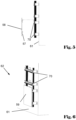
Figs. 3-4 ), which may be performed in a plant, a workshop, or on a jobsite, a set ofhangers 57 each having anupper leg 67 comprising ahook 73, alower leg 68, and one or several through-holes 69 is fastened to theback side 60 of thefaçade panel 58 by inserting apanel fastener 41 through each of the through-holes 69 into one of theblind holes 63, using anelectric screw gun 71 or similar and a preferably torque-controlledsetting bit 72. Theupper leg 67 and thelower leg 68 protrude from thefaçade panel 58 in a thickness direction of the upper orlower leg back side 60, when thehanger 57 is fastened to thefaçade panel 58. Two or more different kinds ofhangers 57 may be used for onefaçade panel 58. A first kind may be configured to carry part of the weight of thefaçade panel 58, another kind may be configured to adjust a position of thefaçade panel 58. - In a further subsequent step (
Figs. 5-6 ), thefaçade panel 58 is attached to thewall 61 by engaging thehangers 57 to asupport 70 formed as a rail previously fastened to thewall 61, as further explained below. Once thefaçade 62 is finished, thefront side 59 of thefaçade panel 58 is visible from an outside view, whereas itsback side 60, thehangers 57, and thefasteners 41 are invisible. - In
Fig. 7 , ahanger 75 configured to be fastened to a façade panel and carry part of the weight of the façade panel, e.g. thefaçade panel 58 shown inFigs. 1-6 , is shown. Thehanger 75 comprises anupper leg 76 having anabutment face 77 configured to face and abut on a support, alower leg 82 configured to abut on a lower portion of the support, and abase portion 83 interconnecting theupper leg 76 and thelower leg 82. Theupper leg 76 comprises ahook 74 configured to engage behind an upper portion of the support. Thebase portion 83 is provided with abore 84 for a panel fastener, e.g. thepanel fastener 41 shown inFig. 4 - In
Figs. 8-10 , ahanger 85 configured to be fastened to a façade panel, carry part of the weight of the façade panel, e.g. thefaçade panel 58 shown inFigs. 1-6 , and adjust a position of the façade panel is shown. Thehanger 85 comprises anupper leg 86 having anabutment face 87 configured to face and abut on a support, alower leg 92 configured to abut on a lower portion of the support, and abase portion 96 interconnecting theupper leg 87 and thelower leg 92. Theupper leg 86 comprises ahook 98 configured to engage behind an upper portion of the support. Thebase portion 96 is provided with two ormore bores 97 for a panel fastener, e.g. thepanel fastener 41 shown inFig. 4 . - The
upper leg 86 is provided with a throughhole 88 extending from theabutment face 87 through theupper leg 86 in a thickness direction 90 (i.e. in a direction crossing the upper leg 86). The throughhole 88 has a hole diameter Dt across thethickness direction 90 and a hole length Lh along the thickness direction. Along its entire length Lh, the throughhole 88 is open to alateral side 89 of theupper leg 86 through anopening 91. Theopening 91 has a cross-sectional width w. - Further, the
hanger 85 comprises anadjustment element 93 formed as an adjustment screw and configured to adjust a distance between theabutment face 87 and the support when theabutment face 87 faces or abuts on the support. To this end, theupper leg 86 is provided with a threaded hole and theadjustment element 93 comprises a threadedshaft 94 running in the threaded hole. Any portion of theadjustment element 93 protruding from theabutment face 87 defines a distance between theabutment face 87 and the support. In order to adjust a vertical position of thehanger 85 and thus the façade panel, theadjustment element 93 is rotated clockwise or counter-clockwise. To this end, theadjustment element 93 comprises anadjustment head 95 having areceptacle 99 for receiving a driver, such as a Torx, Philipps, Hex, SL, Allen, Square or similar driver. - In
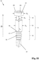
Fig. 11 , a fixingelement 10 formed as a fixing screw is shown. The fixingelement 10 has ashaft 11, ahead 21 and adrill tip 31. Theshaft 11 comprises afastening portion 12, a protrudingportion 13 and aneck portion 14. Thedrill tip 31 joins thefastening portion 12 and enables thefastening portion 12 to penetrate and drill into a support, e.g. thesupport 70 shown inFigs. 5-6 . Thefastening portion 12 comprises a self-tappingthread 15 to fasten the fixingelement 10 to the support. - The protruding
portion 13 joins thefastening portion 12 in a protrudingdirection 20 and protrudes from the support in the protrudingdirection 20 when the fixingelement 10 is fastened to the support. The protrudingportion 13 has a protruding-portion diameter Dp across the protrudingdirection 20 and a protruding-portion length Lp along the protrudingdirection 20. Theshaft 11 comprises astop 16 formed as a step which abuts on the support when the fixingelement 10 is fastened to the support. Thestop 16 comprises a taperedchamfer 17 to align the fixingelement 10 such that the protrudingdirection 20 is oriented perpendicular to a surface of the support while thestop 16 abuts on the support. - The
neck portion 14 joins the protrudingportion 13 in the protrudingdirection 20 and has a neck diameter dn across the protrudingdirection 20 and a neck length Ln along the protrudingdirection 20. Thehead 21 joins theneck portion 14 in the protrudingdirection 20 and has a head diameter dh across the protrudingdirection 20. Thehead 21 has anend face 22 facing in the protrudingdirection 20 and provided with areceptacle 23 for a driver, e.g. a Torx driver, enabling a user to rotationally drive the fixingelement 10 and fasten the fixingelement 10 to the support, e.g. by using a power-driven screwdriver. -
Figs. 12-14 demonstrate a method of attaching a façade panel (not shown for better visibility) to awall 54 by using afastening system 50 comprising thehanger 85 shown inFigs. 8-10 , twofastening elements 52 and the fixingelement 10 shown inFig.11 . - In an early step (
Fig. 12 ), after thehanger 85 has been fastened to the the façade panel by thefastening elements 52, e.g. as shown inFigs. 1-4 , and after asupport 51 formed as a rail is fastened to thewall 54 e.g. by asupport fastener 53, thehanger 85 is positioned on thesupport 51. The abutment face of theupper leg 86 abuts on thesupport 51 and thehook 98 engages behind thesupport 51. Then, a horizontal position of thehanger 85 and the façade panel is adjusted as desired by sliding thehanger 85 horizontally along thesupport 51. - In a subsequent step (
Figs. 13-14 ), the fixingelement 10 is inserted through the throughhole 88 and fastened to thesupport 51 by the drill tip and the fastening portion of the fixingelement 10. The protruding portion of the fixingelement 10 thereby protrudes from thesupport 51 in a vertical protruding direction through the throughhole 88. The protruding-portion diameter Dp is smaller than the hole diameter Dt, and the protruding-portion length Lp is greater than the hole length Lh, thereby allowing theupper leg 86 and thehanger 85 to vertically move with respect to thesupport 51. On the other hand, the protruding-portion diameter Dp is greater than the opening width w, thereby fixing the horizontal position of thehanger 85 and the façade panel with respect to thesupport 51. - Then, a vertical position of the
hanger 85 and the façade panel is adjusted as desired by moving theadjustment element 93 against thesupport 51, e.g. by rotationally driving the adjustment head of the adjustment element, in order to adjust a distance between theupper leg 86 and thesupport 51 in the vertical direction. During such a vertical adjustment, the through hole of theupper leg 86 slides on the protruding portion of the fixing element. While the vertical position of thehanger 85 may be adjusted before the fixingelement 10 is fastened to thesupport 51, it is desirable to fix the horizontal position of thehanger 85 before adjusting its vertical position. -
Figs. 15-18 demonstrate a method of removing the façade panel (not shown for better visibility) from thewall 54 using thefastening system 50. The method starts from the fixed position of thefastening system 50 after fastening thehanger 85 to the support 51 (Fig. 15 ). - In a first step (
Fig. 16 ), the façade panel and thehanger 85 are lifted along the vertical direction such that the throughhole 88 of theupper leg 86 is on the same level as theneck portion 14 of the fixingelement 10. As described above, the protruding-portion diameter Dp is smaller than the hole diameter Dt, thereby allowing this vertical movement. - In a subsequent step (
Fig. 17 ), the façade panel and thehanger 85 are moved horizontally along a lateral direction such that theneck portion 14 of the fixingelement 10 passes theopening 91. The neck diameter dn is smaller than the opening width w, and the neck length Ln is greater than the hole length Lh, thereby allowing this horizontal movement. It is to be noted that the protruding-portion diameter Dp is greater than the opening width w, thereby fixing the horizontal position of the façade panel and thehanger 85 unless theupper leg 86 is lifted to the level of theneck portion 14. The head diameter dh is greater than the hole diameter dt, the head thereby acting as a stop for the lifting movement of theupper leg 86. Unintentional removing the façade panel e.g. by wind is thus unlikely. - In a further subsequent step (
Fig. 18 ), the façade panel and thehanger 85 are moved away from thewall 54 such that the façade panel is free. In this way, the façade panel may be removed from the wall e.g. for repair or replacement, without the need to remove any other panels above. Also, the vertical position of the façade panel may be readjusted, by turning the adjustment element while the panel is taken off the wall. Reassembling the façade panel to the wall is performed by the opposite movements in the opposite order. - While the invention has been described with reference to its preferred embodiments, it will be understood by those skilled in the art that various changes may be made and equivalents may be substituted for elements thereof without departing from the true spirit and scope of the invention. All elements and features of the disclosed embodiments may be present individually or in any combination in all other embodiments, as long as not contradicting to each other. In addition, many modifications may be made to adapt a particular situation or material to the teaching of the invention without departing from its essential teachings.
Claims (15)
- A fastening system for fastening a façade panel to a support, comprising:- a hanger configured to be fastened to the façade panel and having an upper leg, wherein the upper leg has an abutment face configured to face, or abut on, the support and is provided with a through hole extending from the abutment face through the leg in a thickness direction, wherein the through hole has a hole diameter across the thickness direction and a hole length along the thickness direction;- a fixing element configured to be fastened to the support having a shaft, the shaft comprising a protruding portion configured to protrude from the support in a protruding direction when the fixing element is fastened to the support and having a protruding-portion diameter across the protruding direction smaller than the hole diameter and a protruding-portion length along the protruding direction greater than the hole length;wherein the protruding portion is configured to extend through the through hole when the abutment face faces or abuts on the support and the fixing element is fastened to the support.
- The fastening system according to claim 1, wherein- the shaft comprises a neck portion following, or joining, the protruding portion in the protruding direction and having a neck diameter smaller than the protruding-portion diameter and a neck length greater than the hole length,- the through hole, along its entire length, is open to a lateral side of the upper leg through an opening having a cross-sectional width smaller than the protruding-portion diameter and greater than the neck diameter.
- The fastening system according to claim 2, wherein the fixing element comprises a head following, or joining, the neck portion in the protruding direction and having a head diameter across the protruding direction greater than the hole diameter.
- The fastening system according to claim 3, wherein the head has an end face facing in the protruding direction and provided with a receptacle for a driver.
- The fastening system according to any one of the preceding claims, wherein the shaft comprises a fastening portion following, or joining, the protruding portion in a direction opposite to the protruding direction and configured to penetrate, or drill into, the support and fasten the fixing element to the support, wherein the shaft comprises a stop, or step, configured to abut on the support when the fixing element is fastened to the support.
- The fastening system according to claim 5, wherein the fastening portion comprises a thread, or self-tapping thread.
- The fastening system according to any of claims 5 and 6, wherein the stop comprises a tapered chamfer.
- The fastening system according to any one of the preceding claims, wherein the fixing element comprises a drill tip following, or joining, the protruding portion in a direction opposite to the protruding direction and configured to penetrate the support.
- The fastening system according to any one of the preceding claims, wherein the hanger, or the upper leg, comprises an adjustment element configured to adjust a distance between the abutment face and the support in the protruding direction when the abutment face faces or abuts on the support.
- The fastening system according to any one of the preceding claims, further comprising a panel fastener configured to fasten the hanger to the façade panel, wherein the upper leg protrudes from the façade panel in a direction transverse to the thickness direction when the hanger is fastened to the façade panel.
- The fastening system according to any one of the preceding claims, wherein the hanger further comprises a lower leg protruding from the façade panel in a direction transverse to the thickness direction when the hanger is fastened to the façade panel and configured to abut on a lower portion of the support when the façade panel is fastened to the support.
- A façade comprising a façade panel, a fastening system according to any one of the preceding claims, and a support, wherein the façade panel is attached to the support by the fastening system.
- The façade according to claim 12, wherein the support comprises a rail fastened to a wall of a building, wherein the hanger engages the rail, thereby attaching, or securing, the façade panel to the wall.
- A method of fastening a façade panel to a support, the method comprising:- providing a hanger having an upper leg, wherein the upper leg has an abutment face and is provided with a through hole extending from the abutment face through the leg in a thickness direction,- fastening the hanger to a back side of the façade panel such that the upper leg protrudes from the façade panel,- positioning the hanger on the support such that the abutment face faces, or abuts on, the support,- providing a fixing element having a shaft, the shaft comprising a protruding portion,- inserting the fixing element through the through hole,- fastening the fixing element to the support such that the protruding portion protrudes from the support in a protruding direction, thereby allowing the upper leg to move with respect to the support along the protruding direction.
- The method according to claim 14, further comprising:- providing the hanger, or the upper leg, with an adjustment element configured to adjust a distance between the abutment face and the support in the protruding direction when the abutment face faces or abuts on the support- adjusting a horizontal position of the façade panel along the support before the fixing element is fastened to the support,- adjusting a vertical position of the façade panel along the support after the fixing element is fastened to the support.
Priority Applications (9)
| Application Number | Priority Date | Filing Date | Title |
|---|---|---|---|
| EP21210968.0A EP4187040A1 (en) | 2021-11-29 | 2021-11-29 | Panel fixing system, façade and method of fixing façade panels to a support |
| KR1020247011556A KR20240112256A (en) | 2021-11-29 | 2022-11-15 | Facade panel fastening system and method for fastening facade panels to supports |
| AU2022398280A AU2022398280A1 (en) | 2021-11-29 | 2022-11-15 | Faqade panel fastening system and method of fastening a faqade panel to a support |
| US18/699,457 US20240401340A1 (en) | 2021-11-29 | 2022-11-15 | Façade, fastening system and method |
| CA3233351A CA3233351A1 (en) | 2021-11-29 | 2022-11-15 | Faqade panel fastening system and method of fastening a faqade panel to a support |
| PCT/EP2022/081865 WO2023094201A1 (en) | 2021-11-29 | 2022-11-15 | Faqade panel fastening system and method of fastening a faqade panel to a support |
| CN202280067937.3A CN118103575A (en) | 2021-11-29 | 2022-11-15 | Facade panel fastening system and method for fastening a facade panel to a support |
| JP2024527057A JP7828448B2 (en) | 2021-11-29 | 2022-11-15 | Facade panel fastening system and method for fastening a facade panel to a support |
| EP22817703.6A EP4441311A1 (en) | 2021-11-29 | 2022-11-15 | Faqade panel fastening system and method of fastening a faqade panel to a support |
Applications Claiming Priority (1)
| Application Number | Priority Date | Filing Date | Title |
|---|---|---|---|
| EP21210968.0A EP4187040A1 (en) | 2021-11-29 | 2021-11-29 | Panel fixing system, façade and method of fixing façade panels to a support |
Publications (1)
| Publication Number | Publication Date |
|---|---|
| EP4187040A1 true EP4187040A1 (en) | 2023-05-31 |
Family
ID=78844800
Family Applications (2)
| Application Number | Title | Priority Date | Filing Date |
|---|---|---|---|
| EP21210968.0A Withdrawn EP4187040A1 (en) | 2021-11-29 | 2021-11-29 | Panel fixing system, façade and method of fixing façade panels to a support |
| EP22817703.6A Pending EP4441311A1 (en) | 2021-11-29 | 2022-11-15 | Faqade panel fastening system and method of fastening a faqade panel to a support |
Family Applications After (1)
| Application Number | Title | Priority Date | Filing Date |
|---|---|---|---|
| EP22817703.6A Pending EP4441311A1 (en) | 2021-11-29 | 2022-11-15 | Faqade panel fastening system and method of fastening a faqade panel to a support |
Country Status (8)
| Country | Link |
|---|---|
| US (1) | US20240401340A1 (en) |
| EP (2) | EP4187040A1 (en) |
| JP (1) | JP7828448B2 (en) |
| KR (1) | KR20240112256A (en) |
| CN (1) | CN118103575A (en) |
| AU (1) | AU2022398280A1 (en) |
| CA (1) | CA3233351A1 (en) |
| WO (1) | WO2023094201A1 (en) |
Cited By (1)
| Publication number | Priority date | Publication date | Assignee | Title |
|---|---|---|---|---|
| US12286798B2 (en) * | 2022-06-24 | 2025-04-29 | Blox, Llc | Three axis clip system for mounting panels to a wall |
Citations (4)
| Publication number | Priority date | Publication date | Assignee | Title |
|---|---|---|---|---|
| DE9311177U1 (en) * | 1993-07-27 | 1993-09-09 | BWM Dübel + Montagetechnik GmbH, 70771 Leinfelden-Echterdingen | Device for fastening plates |
| DE29906465U1 (en) * | 1999-04-13 | 1999-07-29 | Deutsche Amphibolin-Werke von Robert Murjahn GmbH & Co KG, 64372 Ober-Ramstadt | Suspension for facade panels on buildings |
| DE102007037271A1 (en) * | 2007-08-07 | 2009-02-12 | Fischerwerke Gmbh & Co. Kg | Plate-like cladding elements fastening device for use in substructure system, has mounting elements hooked into carrier and mounting elements rotatably supported at carrier around longitudinal axis of carrier |
| US20200354966A1 (en) * | 2019-05-07 | 2020-11-12 | Sfs Intec Holding Ag | Facade element holder and method for mounting same |
Family Cites Families (7)
| Publication number | Priority date | Publication date | Assignee | Title |
|---|---|---|---|---|
| US3563578A (en) * | 1969-03-19 | 1971-02-16 | Goodyear Aerospace Corp | Panel joint |
| US4070835A (en) * | 1976-08-09 | 1978-01-31 | Safama | Device intended for the hooking of panels on a wall in order to constitute a covering on this wall |
| JP4328438B2 (en) | 1999-12-27 | 2009-09-09 | 一雄 黒澤 | Interior panel material, mounting bracket for exterior panel material, and mounting method thereof |
| US8468765B1 (en) * | 2012-03-30 | 2013-06-25 | Jong Sung Kim | Panel fixing device |
| US8833017B1 (en) * | 2013-10-02 | 2014-09-16 | Rong-Jun Huang | Rapid hanging curtain wall unit for a wall assembling structure |
| US9926707B1 (en) * | 2016-12-16 | 2018-03-27 | McElroy Metal Mill, Inc. | Metal panel wall cover system |
| FI3536989T3 (en) | 2018-03-06 | 2023-09-14 | SFS Group International AG | Façade plate screw and fastening arrangement using the same |
-
2021
- 2021-11-29 EP EP21210968.0A patent/EP4187040A1/en not_active Withdrawn
-
2022
- 2022-11-15 CA CA3233351A patent/CA3233351A1/en active Pending
- 2022-11-15 EP EP22817703.6A patent/EP4441311A1/en active Pending
- 2022-11-15 AU AU2022398280A patent/AU2022398280A1/en active Pending
- 2022-11-15 US US18/699,457 patent/US20240401340A1/en active Pending
- 2022-11-15 WO PCT/EP2022/081865 patent/WO2023094201A1/en not_active Ceased
- 2022-11-15 JP JP2024527057A patent/JP7828448B2/en active Active
- 2022-11-15 KR KR1020247011556A patent/KR20240112256A/en active Pending
- 2022-11-15 CN CN202280067937.3A patent/CN118103575A/en active Pending
Patent Citations (4)
| Publication number | Priority date | Publication date | Assignee | Title |
|---|---|---|---|---|
| DE9311177U1 (en) * | 1993-07-27 | 1993-09-09 | BWM Dübel + Montagetechnik GmbH, 70771 Leinfelden-Echterdingen | Device for fastening plates |
| DE29906465U1 (en) * | 1999-04-13 | 1999-07-29 | Deutsche Amphibolin-Werke von Robert Murjahn GmbH & Co KG, 64372 Ober-Ramstadt | Suspension for facade panels on buildings |
| DE102007037271A1 (en) * | 2007-08-07 | 2009-02-12 | Fischerwerke Gmbh & Co. Kg | Plate-like cladding elements fastening device for use in substructure system, has mounting elements hooked into carrier and mounting elements rotatably supported at carrier around longitudinal axis of carrier |
| US20200354966A1 (en) * | 2019-05-07 | 2020-11-12 | Sfs Intec Holding Ag | Facade element holder and method for mounting same |
Cited By (1)
| Publication number | Priority date | Publication date | Assignee | Title |
|---|---|---|---|---|
| US12286798B2 (en) * | 2022-06-24 | 2025-04-29 | Blox, Llc | Three axis clip system for mounting panels to a wall |
Also Published As
| Publication number | Publication date |
|---|---|
| EP4441311A1 (en) | 2024-10-09 |
| JP2024538363A (en) | 2024-10-18 |
| CA3233351A1 (en) | 2023-06-01 |
| KR20240112256A (en) | 2024-07-18 |
| WO2023094201A1 (en) | 2023-06-01 |
| JP7828448B2 (en) | 2026-03-11 |
| US20240401340A1 (en) | 2024-12-05 |
| AU2022398280A1 (en) | 2024-04-11 |
| CN118103575A (en) | 2024-05-28 |
Similar Documents
| Publication | Publication Date | Title |
|---|---|---|
| CN108396931B (en) | Dry hanging device for building wall tile | |
| US4883396A (en) | Dual expansion and non-expansion anchor | |
| WO2021031509A1 (en) | Wall leveling assembly and mounting method therefor | |
| US20130145704A1 (en) | Window installation assembly and method to install windows | |
| US20240401340A1 (en) | Façade, fastening system and method | |
| US6662511B1 (en) | Devices and methods for securing an object to a first structure through a hole in a second structure | |
| US11091916B2 (en) | Facade element holder and method for mounting same | |
| FI3536989T3 (en) | Façade plate screw and fastening arrangement using the same | |
| CN211396423U (en) | Leveling structure | |
| MXPA03003491A (en) | Device for holding panels and separating element. | |
| CA3161995A1 (en) | Fastener and facade | |
| US11549269B2 (en) | Standoff for mounting panel and method for mounting panels | |
| US20230243205A1 (en) | Accessory structure mounting system | |
| JPH083259B2 (en) | Connecting device for structures such as stone materials | |
| US20210088069A1 (en) | Screw Fasteners for Use in Building Construction | |
| RU2517095C2 (en) | Fixator of angular plank | |
| KR200196201Y1 (en) | The fixation device of the outdoor decorative material of a building | |
| CN112227633A (en) | Wall whole brick suspension structure and construction method | |
| US20240066671A1 (en) | Centering device and fastening arrangement | |
| US20250344849A1 (en) | System and baseplate for floating fixtures | |
| CN113719050B (en) | Wall surface dry-hanging ceramic tile with leveling mechanism | |
| EP3945194B1 (en) | Installation spacer and use of such a device | |
| AU2019232872B2 (en) | Screw fasteners for use in building construction | |
| JP2530988Y2 (en) | A jig for adjusting the surface of building panels | |
| UA5766U (en) | Method for installation of a mark at finishing works |
Legal Events
| Date | Code | Title | Description |
|---|---|---|---|
| PUAI | Public reference made under article 153(3) epc to a published international application that has entered the european phase |
Free format text: ORIGINAL CODE: 0009012 |
|
| STAA | Information on the status of an ep patent application or granted ep patent |
Free format text: STATUS: THE APPLICATION HAS BEEN PUBLISHED |
|
| AK | Designated contracting states |
Kind code of ref document: A1 Designated state(s): AL AT BE BG CH CY CZ DE DK EE ES FI FR GB GR HR HU IE IS IT LI LT LU LV MC MK MT NL NO PL PT RO RS SE SI SK SM TR |
|
| STAA | Information on the status of an ep patent application or granted ep patent |
Free format text: STATUS: THE APPLICATION IS DEEMED TO BE WITHDRAWN |
|
| 18D | Application deemed to be withdrawn |
Effective date: 20231201 |