EP4186566B1 - Brandschutzklappe mit einem zumindest eine gehäusewandung aufweisenden gehäuse und mit einem zwischen einer offenstellung und einer schliessstellung um eine drehachse herum verschwenkbar gelagerten klappenblatt - Google Patents
Brandschutzklappe mit einem zumindest eine gehäusewandung aufweisenden gehäuse und mit einem zwischen einer offenstellung und einer schliessstellung um eine drehachse herum verschwenkbar gelagerten klappenblatt Download PDFInfo
- Publication number
- EP4186566B1 EP4186566B1 EP21210570.4A EP21210570A EP4186566B1 EP 4186566 B1 EP4186566 B1 EP 4186566B1 EP 21210570 A EP21210570 A EP 21210570A EP 4186566 B1 EP4186566 B1 EP 4186566B1
- Authority
- EP
- European Patent Office
- Prior art keywords
- flap
- housing
- fire damper
- damper according
- open position
- Prior art date
- Legal status (The legal status is an assumption and is not a legal conclusion. Google has not performed a legal analysis and makes no representation as to the accuracy of the status listed.)
- Active
Links
Images


Classifications
-
- A—HUMAN NECESSITIES
- A62—LIFE-SAVING; FIRE-FIGHTING
- A62C—FIRE-FIGHTING
- A62C2/00—Fire prevention or containment
- A62C2/06—Physical fire-barriers
- A62C2/12—Hinged dampers
-
- F—MECHANICAL ENGINEERING; LIGHTING; HEATING; WEAPONS; BLASTING
- F24—HEATING; RANGES; VENTILATING
- F24F—AIR-CONDITIONING; AIR-HUMIDIFICATION; VENTILATION; USE OF AIR CURRENTS FOR SCREENING
- F24F13/00—Details common to, or for air-conditioning, air-humidification, ventilation or use of air currents for screening
- F24F13/08—Air-flow control members, e.g. louvres, grilles, flaps or guide plates
- F24F13/10—Air-flow control members, e.g. louvres, grilles, flaps or guide plates movable, e.g. dampers
- F24F13/14—Air-flow control members, e.g. louvres, grilles, flaps or guide plates movable, e.g. dampers built up of tilting members, e.g. louvre
-
- F—MECHANICAL ENGINEERING; LIGHTING; HEATING; WEAPONS; BLASTING
- F24—HEATING; RANGES; VENTILATING
- F24F—AIR-CONDITIONING; AIR-HUMIDIFICATION; VENTILATION; USE OF AIR CURRENTS FOR SCREENING
- F24F11/00—Control or safety arrangements
- F24F11/30—Control or safety arrangements for purposes related to the operation of the system, e.g. for safety or monitoring
- F24F11/32—Responding to malfunctions or emergencies
- F24F11/33—Responding to malfunctions or emergencies to fire, excessive heat or smoke
- F24F11/35—Responding to malfunctions or emergencies to fire, excessive heat or smoke by closing air passages
Definitions
- the invention relates to a fire damper with a housing having a housing wall and with a damper blade, preferably made of calcium silicate, which is mounted preferably centrally on the housing cross-section and can pivot about an axis of rotation between an open position and a closed position and has two opposite damper surfaces connected to one another by a circumferential end face, wherein the axis of rotation divides the damper blade into two damper blade halves, wherein two opposite bearing points forming the axis of rotation are provided for supporting the damper blade and wherein the damper blade can be pivoted against the restoring force of a spring element from its closed position into its open position aligned parallel to the flow direction.
- a damper blade preferably made of calcium silicate
- DE 10 2019 102 185 A1 An industrial valve with at least one flap device for shutting off pipes with a large nominal diameter is known.
- DE 10 2009 011 501 A1 discloses a triggering device for a damper blade of a fire damper.
- the object of the invention is to avoid the aforementioned disadvantages and to provide a fire damper which can be used without regular and complex cleaning of the front surface of the damper blade even in contaminated air streams such as kitchen exhaust ducts or laboratory exhaust ducts.
- each protective device is provided inside the housing for shielding the end faces in the open position of the damper blade, each of which extends along the relevant end face in the open position of the damper blade, wherein each protective device forms a cavity with the end face assigned to it that is sealed off from the interior of the housing by at least one cold seal, so that each of the two end faces is completely shielded by the protective device assigned to it in the open position of the damper blade.
- the damper blade With central mounting of the damper blade, the damper blade is located in the middle of the housing and thus divides the housing cross-section preferably into two equally sized housing cross-sectional areas. In its open position, the flowing medium flows around the damper blade in the area of both damper surfaces.
- the design according to the invention shields, i.e. protects, the front surface of the damper blade in the open position from the flowing medium.
- the protective device is made of a suitable material, such as sheet metal. In this way, the front surface The damper blade is protected from contamination, i.e., from dirt or gases in the air stream.
- the front face In the open position, the front face is located in a cavity, i.e., a protective space formed by the front face, the protective device, and the cold seal.
- the protective device has a width B that is at least equal to or greater than the thickness D of the damper blade.
- the width B of the protective device is only slightly or at least not significantly greater than the thickness D of the damper blade, so that the free flow cross-section is blocked as little as possible in the open position of the damper blade.
- the housing can have a round housing cross-section with a circumferential housing wall and each of the two protective devices can have a curved contour adapted to the end face assigned to it, wherein each protective device is arranged in alignment with the axis of rotation as seen in the direction of flow and wherein the distance between the axis of rotation and each protective device is slightly greater than the radius of the damper blade.
- the housing it is also possible for the housing to have a rectangular cross-section and for the housing wall to be formed by four housing walls, each of the two protective devices being formed, on the one hand, from the two housing walls oriented orthogonally to the axis of rotation and, on the other hand, from a protective element oriented parallel to the axis of rotation and extending between the housing walls oriented orthogonally to the axis of rotation.
- Each protective element is arranged in alignment with the axis of rotation, as seen in the direction of flow, and the distance between the axis of rotation and the protective element is slightly greater than the distance between the axis of rotation and the relevant end face of the damper blade adjacent to the protective element.
- the protective device is formed, on the one hand, by the two housing walls oriented orthogonally to the axis of rotation and, on the other hand, by the protective element oriented parallel to the axis of rotation and extending between the housing walls orthogonally to the axis of rotation.
- the corresponding end face can have a cold seal on at least one of its two edges, extending along this edge and projecting in the longitudinal direction of the damper blade relative to the end face.
- the cold seal in question is arranged on the damper blade and is therefore displaced accordingly.
- the cold seal also serves to seal the damper blade in its closed position against the housing.
- the damper blade can have a circumferential cold seal on each of its two edges, extending along the respective edge and protruding from the end face in the longitudinal direction of the damper blade.
- both protective devices with their respective associated end faces of the damper blade halves, form a common circumferential cavity sealed from the interior of the housing by the two cold seals.
- the rotation axis extends through this common cavity.
- each protective device it is also entirely possible for each protective device to form its own cavity with its adjacent end face. This creates at least two cavities in the open position. Of course, it is also possible to create additional cavities, for example, in the area of a bearing point, by selecting and arranging suitable cold seals.
- At least one protective device may be provided with a cold seal on at least one of its two longitudinal edges, preferably on both of its longitudinal edges, to seal the cavity formed between the protective device, on the one hand, and the end face of the damper blade in its open position facing it, on the other hand.
- the corresponding cold seal serves only to seal the cavity between the protective device and the end face of the damper blade in the open position.
- a heat seal that expands when exposed to heat can be provided on the front surface of each half of the damper blade.
- the size of the damper blade is matched to the housing so that in the closed position of the damper blade, of the housing and the heat seal in the state not yet expanded by the effects of heat, a circumferential movement gap remains.
- the housing can have a heat seal on the inside, at least in the portion extending along the circumference of the damper blade in the closed position, which expands upon exposure to heat. Even with such a design, the size of the damper blade is matched to the housing such that, in the closed position of the damper blade, a circumferential movement gap remains between the inside of the housing and the heat seal, in a state not yet expanded by the effects of heat.
- At least one protective device can be designed as a rail or profile rail over part of its length, preferably over its entire length.
- the rail can be designed as a flat strip made of a suitable material, such as metal.
- the width B of the strip is preferably equal to or slightly greater than the thickness D of the damper blade.
- At least one protective device can have a convex shape over part of its length, preferably over its entire length.
- the distance C 1 between a longitudinal edge of the protective device and the end face of the damper blade is smaller than the distance C 2 between the area located between the two longitudinal edges of the protective device and the end face of the damper blade.
- At least one profile rail can be designed as an angle rail with two angled surfaces aligned at an angle, preferably at a right angle, to form an abutting edge, wherein the abutting edge is arranged facing away from the end face of the damper blade in its open position.
- Such a design improves the flow behavior, since the air flow is deflected upwards and downwards by the protective device facing against the flow direction. The air flow then flows along the two damper surfaces of the damper blade in its open position. damper blade and is brought together again after passing the protective device pointing in the direction of flow.
- each protective device can merge, at least over part of its length, preferably over its entire length, into a cover element extending in the direction of the axis of rotation, wherein the cover elements are provided diametrically opposite one another and are aligned parallel to the direction of flow and wherein the cover elements are arranged such that, in the open position of the damper blade, each cover element covers the adjacent surface of the damper blade half.
- each cover element extends from one housing wall aligned orthogonally to the axis of rotation to the opposite, other housing wall aligned orthogonally to the axis of rotation.
- At least one cover element can extend in the direction of flow so far that the damper blade in its closed position rests against the free edge of the cover element.
- the free edge of one cover element is positioned upstream of the axis of rotation by half the thickness of the damper blade in the direction of flow
- the free edge of the other cover element is positioned downstream of the axis of rotation by half the thickness of the damper blade in the direction of flow, so that the two mutually facing free edges of the cover elements are offset by the thickness of the
- the damper blades are arranged offset from one another in the direction of flow.
- Each of the two flap surfaces can have, in the area that adjoins the area covered by the cover element when the flap leaf is in the open position, a cold seal having four edges arranged at right angles to one another, preferably in the shape of a frame. Three of the edges of each of the two cold seals protrude laterally opposite the end face in the longitudinal direction of the flap leaf, and the cover element, with its edge region, is in sealing contact with the fourth edge of the respective cold seal when the flap leaf is in the open position.
- Each of the two cold seals can be designed as a continuous plate that is, for example, glued or screwed onto the respective area of the flap surface. In this case, it extends completely over the respective area of the flap surface.
- a cold seal to be designed as a square frame.
- the frame can be formed as a single piece from a cold seal. It is also possible for the frame to consist of several contacting sealing sections that together form a circumferential cold seal.
- a flat gasket or a profiled gasket for example with a round or oval profile, can be provided as a cold seal.
- the two cold seals arranged in diametrically opposite regions of the two flap surfaces can be connected to each other in the area of each bearing point by a cold seal extending across the end face.
- Each of the two flap surfaces can be in the area that, in the open position of the flap leaf, is adjacent to the area covered by the cover element adjoins, have a surface element, preferably designed as a sheet metal, that completely covers the relevant area.
- a surface element preferably designed as a sheet metal
- At least one protective device and the adjacent cover element can be formed as a single piece. Of course, a multi-piece design is also possible. At least one protective device and the adjacent cover element can be formed from a single sheet, for example.
- At least one of the two flap surfaces can have a surface element, preferably made of sheet metal, that completely covers the respective flap surface. This surface element protects the respective area of the flap blade from the airflow.
- At least one protective device can have at least one supply opening, preferably accessible from outside the housing, for supplying a gaseous medium, preferably air, into the respective cavity.
- a gaseous medium preferably air
- At least one supply opening can be connected to a pressure generating device, preferably to a pump or a fan.
- At least one protective device can have at least one outlet opening, preferably provided with a non-return device, for discharging a gaseous medium, preferably air, from the cavity into the interior of the housing.
- the non-return device prevents air from the interior of the housing from passing through the outlet opening into the cavity.
- a negative pressure develops in the cavity of the "cassette.” To compensate for the negative pressure, uncontaminated air flows from outside the fire damper into the cavity of the "cassette.” This prevents contaminated air flowing through the fire damper from penetrating the "cassette.”
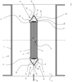
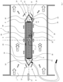
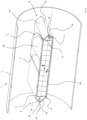
- Each fire damper has a housing with a housing wall 1 and a damper blade 3 pivotably mounted centrally with respect to the housing cross-section between an open position and a closed position about a rotation axis 2.
- the damper blade 3 has two opposing damper surfaces 5, 6 connected to each other by a circumferential end face 4.
- the damper blade 3 is made, for example, of calcium silicate.
- the rotational axis 2 of the damper blade 3 divides the damper blade 3 into two halves, whereby two opposing bearing points forming the rotational axis 2 are provided for supporting the damper blade 3 and the damper blade 3 can be pivoted against the restoring force of a spring element (not shown) from its closed position into its open position aligned parallel to the flow direction.
- the open position is, for example, in Fig. 1 shown.
- the housing has a rectangular cross-section and the housing wall 1 is formed by four housing walls 7.
- the housing has a round cross-section with a circumferential housing wall 1.
- the damper blade 3 is in its closed position and in Fig. 13 the flap 3 is shown in its open position.
- two protective devices 8 are provided to shield the end face 4 of the damper blade 3 when the damper blade 3 is in its open position.
- the protective devices 8 each extend along the respective end face 4 when the damper blade 3 is in its open position.
- the end face 4 is completely shielded by its assigned protective device 8 in the area of both damper blade halves. The end face 4 is thus protected from the air flow in the flow direction 11.
- Each of the two protective devices 8 is formed, on the one hand, from the two housing walls 7 aligned orthogonally to the axis of rotation 2 and, on the other hand, from a protective element 12 aligned parallel to the axis of rotation 2 and extending between the housing walls 7 aligned orthogonally to the axis of rotation 2.
- Each protective element 12 is arranged in alignment with the axis of rotation 2, as seen in the flow direction 11. The distance between the axis of rotation 2 and the protective element 12 is slightly greater than the distance between the axis of rotation 2 and the relevant end face 4 of the damper blade 3 adjacent to the protective element 12.
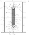
- Each of the two protective devices 8 has a curved contour adapted to its associated end face 4.
- each protective device 8 is arranged in alignment with the rotation axis 2, as seen in the flow direction 11, and the distance between the rotation axis 2 and each protective device 8 is slightly larger than the radius of the damper blade 3.
- the protective device 8 is designed as a profile rail over part of its length, specifically in the area between the two housing walls 7, which run orthogonally to the axis of rotation 2.
- the profile rail is designed as an angle rail with two angled surfaces 14 aligned at right angles to one another, forming an abutting edge 13.
- the abutting edge 13 points away from the end face 4 of the damper blade 3 in its open position.
- the protective device 8 is designed - in this case over its entire length - as a profile rail, wherein the profile rail has two angular surfaces 14 aligned at a right angle to one another to form an abutting edge 13.
- the damper blade 3 has two edges 15, regardless of its contour, each edge 15 being circumferential.
- the two edges 15 are spaced apart from each other, the distance between the edges 15 corresponding to the thickness of the damper blade 3.
- each flap leaf half has two semicircular, parallel edges 15.
- each damper blade half again has two parallel edges 15, wherein each edge 15 of each damper blade half consists of three edge sections, namely one edge section aligned parallel to the rotation axis 2 and two edge sections aligned orthogonal to the rotation axis 2.
- the damper blade 3 has on each of its two edges 15 a cold seal 9 extending along the respective edge 15 and projecting in the longitudinal direction of the damper blade 3 relative to the end face 4.
- each cold seal 9 in the open position of the damper blade 3 the angled surface 14 of the profile rail assigned to it, so that a cavity 10 with an approximately triangular cross-section is formed.
- the housing has a heat seal 17 on the inside in the partial area that extends along the circumference of the damper blade 3 in the closed position, which expands when exposed to heat.
- the damper blade 3 is oriented orthogonally to the flow direction 11 in its closed position and parallel to the flow direction 11 in its open position.
- a heat seal 17 which expands when exposed to heat is provided on the end face 4 of each damper blade half.
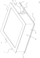
- each flap surface 5, 6 additionally has a surface element 18, preferably designed as a sheet metal, which completely covers the respective flap surface 5, 6.
- a surface element 18, preferably designed as a sheet metal which completely covers the respective flap surface 5, 6.
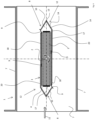
- each protective device 8 merges, at least over part of its length, namely in the region extending between the housing walls 7 aligned orthogonally to the axis of rotation 2, into a cover element 20 extending in the direction of the axis of rotation 2.
- a cover element 20 can be formed, for example, from sheet metal.
- the cover elements 20 are provided diametrically opposite one another with respect to the axis of rotation 2 and are aligned parallel to the flow direction 11.
- the cover elements 20 are arranged such that, in the open position of the damper blade 3, each cover element 20 covers the respective adjacent region of the damper surface 5, 6.
- each of the two flap surfaces 5, 6 is provided in the area which, in the open position of the flap leaf 3, adjoins the area covered by the cover element 20 with a a surface element 18 completely covering the relevant area.
- This surface element 18 can be a sheet metal.
- Fig. 5 shows, the two protective devices 8 with the adjacent cover element 20 form a kind of "cassette” into which the damper blade 3 can be pivoted and is "received” in its open position.
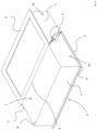
- each of the two flap surfaces 5, 6 has, in the area which, in the open position of the flap leaf 3, adjoins the area covered by the cover element 20, a cold seal 9 which has four edges arranged at a right angle to one another.
- Each of the two cold seals 9 is arranged and dimensioned such that three of its edges protrude laterally opposite the end face 4 in the longitudinal direction of the flap leaf 3.
- the edge region of each cover element 20 is in sealing contact with the fourth edge of the adjacent cold seal 9.
- the cold seal 9 can also be provided on the protective device 8. In such a configuration, the seal would be achieved by an inverted arrangement of the cold seal 9.
- each cold seal 9 is frame-like.
- the two cold seals 9 arranged on the two flap surfaces 5, 6 are connected to one another in the area of each bearing point by a cold seal 9 extending over the end face 4. This creates two cavities 10 when the flap leaf 3 is in the open position.
- the arrangement of the cold seals 9 seals the gaps between each protective device 8 and the flap leaf 3. In addition, tightness is achieved when the flap leaf 3 is in the closed position.
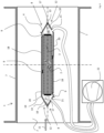
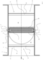
- Each of the two protective devices 8 has a supply opening 21 accessible from outside the housing for supplying a gaseous medium, for example air, into the respective cavity 10.
- a pressure generating device 22 such as a pump or a fan, is provided, which is arranged outside the housing and is connected, for example, via a hose to the respective supply opening 21.
- an overpressure can be generated in each of the two cavities 10 compared to the interior of the housing, so that even if the cold seals 9 do not provide sufficient sealing, the air flowing inside the housing does not enter the cavities 10.
- Other designs are also conceivable instead of a hose.
- the air could be directed directly into the cavity 10 through a corresponding opening in the housing.
- FIG. 7 A design is shown in which the protective device 8 facing against the flow direction 11 has an inlet opening 21 accessible from outside the housing, and the protective device 8 facing in the flow direction 11 has an outlet opening 24 provided with a non-return device 23. Air flows in from the atmosphere via the inlet opening 21. In the area of the outlet opening 24, the faster air flow inside the housing creates a negative pressure in the area of the cross-sectional constriction of the "cassette" of the damper blade 3, which is formed by the two protective devices 8 with the adjacent cover element 20, so that air is drawn out of the cavity 10 into the interior of the housing.
- the outlet opening 24 is therefore a type of Venturi nozzle.
- the non-return device 23 may, for example, be a rubber strip which allows flow in the direction of arrow 25 but prevents flow opposite to the direction of arrow 25.
- the flow velocity v+ of the air flow at the outlet opening 24 is greater than the flow velocity v of the air flow in the flow direction 11 before and after the damper blade 3.
- the flow velocity vF is understood to be the afterflow velocity of the air flow.
- the pressure pF in the cavity 10 is greater than the pressure pL. of the air flow at the outlet opening 24 of the cavity 10.
- the flow velocity v+ is greater in the area of the constriction than in the flow direction 11 before and after the damper blade 3.
- the respective damper blade 3 has an arrangement of the cold seals 9 according to Fig. 11
- the two cavities 10 formed between the end face 4 and the two protective devices 8 in the open position of the damper blade 3 are connected to each other via a flow channel 26.
- Fig. 8 shows a damper blade 3, which has a circumferential cold seal 9 on each of its two edges 15, extending along the respective edge 15 and protruding in the longitudinal direction of the damper blade 3 relative to the end face 4. In the open position, a circumferential cavity 10 is formed.
- a cold seal 9 is provided in the area of each bearing point, which extends over the end face 4 and connects the two circumferential cold seals 9. This creates two cavities 10.
- a cold seal 9 is provided, which extends over the end face 4 and connects the two circumferential cold seals 9. With such a design, a total of four cavities 10 are created.
- the two protective devices 8 are formed, on the one hand, from the two housing walls 7 (not shown) aligned orthogonally to the axis of rotation 2 and, on the other hand, from a protective element 12 designed as a profile rail, aligned parallel to the axis of rotation 2 and extending between the housing walls 7 aligned orthogonally to the axis of rotation 2.
- the profile rail is designed as an angle rail with two angle surfaces 14 aligned at a right angle to each other to form an abutting edge 13, wherein the abutting edge 13 is arranged pointing away from the end face 4 of the damper blade 3 in its open position.
- the profile rail has a convex shape
- the profile rail is made of flat steel.
- each of the two longitudinal edges 19 of each protective device 8 has an end region 16 which is angled relative to the adjacent angled surface 14 in the direction of the damper blade 16 in the open position.
- this is the longitudinal edge 19 which points in the direction of the displacement direction 26.
Landscapes
- Engineering & Computer Science (AREA)
- Chemical & Material Sciences (AREA)
- Combustion & Propulsion (AREA)
- Mechanical Engineering (AREA)
- General Engineering & Computer Science (AREA)
- Health & Medical Sciences (AREA)
- Public Health (AREA)
- Business, Economics & Management (AREA)
- Emergency Management (AREA)
- Air-Flow Control Members (AREA)
Priority Applications (3)
| Application Number | Priority Date | Filing Date | Title |
|---|---|---|---|
| PL21210570.4T PL4186566T3 (pl) | 2021-11-25 | 2021-11-25 | Klapa przeciwpożarowa z mającą co najmniej jedną ściankę obudową i z osadzonym przechylnie wokół osi obrotu między położeniem otwartym i położeniem zamkniętym skrzydłem klapy |
| ES21210570T ES3036656T3 (en) | 2021-11-25 | 2021-11-25 | Fire damper with a housing having at least one housing wall and with a flap leaf mounted in such a manner that it can be pivoted about an axis of rotation between an open position and a closed position |
| EP21210570.4A EP4186566B1 (de) | 2021-11-25 | 2021-11-25 | Brandschutzklappe mit einem zumindest eine gehäusewandung aufweisenden gehäuse und mit einem zwischen einer offenstellung und einer schliessstellung um eine drehachse herum verschwenkbar gelagerten klappenblatt |
Applications Claiming Priority (1)
| Application Number | Priority Date | Filing Date | Title |
|---|---|---|---|
| EP21210570.4A EP4186566B1 (de) | 2021-11-25 | 2021-11-25 | Brandschutzklappe mit einem zumindest eine gehäusewandung aufweisenden gehäuse und mit einem zwischen einer offenstellung und einer schliessstellung um eine drehachse herum verschwenkbar gelagerten klappenblatt |
Publications (2)
| Publication Number | Publication Date |
|---|---|
| EP4186566A1 EP4186566A1 (de) | 2023-05-31 |
| EP4186566B1 true EP4186566B1 (de) | 2025-05-14 |
Family
ID=78789901
Family Applications (1)
| Application Number | Title | Priority Date | Filing Date |
|---|---|---|---|
| EP21210570.4A Active EP4186566B1 (de) | 2021-11-25 | 2021-11-25 | Brandschutzklappe mit einem zumindest eine gehäusewandung aufweisenden gehäuse und mit einem zwischen einer offenstellung und einer schliessstellung um eine drehachse herum verschwenkbar gelagerten klappenblatt |
Country Status (3)
| Country | Link |
|---|---|
| EP (1) | EP4186566B1 (pl) |
| ES (1) | ES3036656T3 (pl) |
| PL (1) | PL4186566T3 (pl) |
Family Cites Families (3)
| Publication number | Priority date | Publication date | Assignee | Title |
|---|---|---|---|---|
| DE102005053480B4 (de) * | 2005-11-09 | 2009-07-23 | Fraunhofer-Gesellschaft zur Förderung der angewandten Forschung e.V. | Brandschutzklappe mit Strömungsprofil |
| DE102009011501B4 (de) * | 2009-03-06 | 2016-06-30 | Werner Wildeboer | Auslöseeinrichtung für ein Klappenblatt einer Brandschutzklappe |
| DE102019102185A1 (de) * | 2019-01-29 | 2020-07-30 | b-teck GmbH | Industriearmatur mit wenigstens einer Klappeneinrichtung zum Absperren von Leitungen mit großer Nennweite |
-
2021
- 2021-11-25 PL PL21210570.4T patent/PL4186566T3/pl unknown
- 2021-11-25 ES ES21210570T patent/ES3036656T3/es active Active
- 2021-11-25 EP EP21210570.4A patent/EP4186566B1/de active Active
Also Published As
| Publication number | Publication date |
|---|---|
| ES3036656T3 (en) | 2025-09-23 |
| EP4186566A1 (de) | 2023-05-31 |
| PL4186566T3 (pl) | 2025-09-01 |
Similar Documents
| Publication | Publication Date | Title |
|---|---|---|
| DE69401553T2 (de) | Statische, dynamische Gasabfuhreinrichtung | |
| DE69400543T2 (de) | Rotierender Schalldämpfer | |
| DE102009011924A1 (de) | Nebenstromkanal eines Turbofantriebwerks | |
| WO2008122507A1 (de) | Shiplap-anordnung | |
| DE102007014836A1 (de) | Luftfilter- und Gebläsevorrichtung für Fahrzeugbelüftungsanlagen | |
| DE102018214560A1 (de) | Luftauslass | |
| DE102014116473A1 (de) | Lüftungsvorrichtung | |
| EP2322866A1 (de) | Drallauslass zur Belüftung von Räumen | |
| DE602004004025T2 (de) | Gesteuerte Klappe für eine rotationssymmetrische Schubdüse eines Strahltriebwerks | |
| EP3751145A1 (de) | Ventilatoreinrichtung | |
| EP4186566B1 (de) | Brandschutzklappe mit einem zumindest eine gehäusewandung aufweisenden gehäuse und mit einem zwischen einer offenstellung und einer schliessstellung um eine drehachse herum verschwenkbar gelagerten klappenblatt | |
| EP1835239B1 (de) | Rückschlagklappenvorrichtung | |
| DE69104335T2 (de) | Kombinierte Vebrennungsluftzu- und Abgasabfuhr. | |
| DE602005001231T2 (de) | Verriegelungsmittel für Gasturbinentriebwerke | |
| DE102010037557A1 (de) | Ablauf für einen Abgaskanal | |
| DE1154252B (de) | Abschirmung von Raumoeffnungen durch einen Luftschleier | |
| EP0943849A1 (de) | Berührungsfreie Dichtung für Strömungsmaschinen | |
| DE19743591A1 (de) | Verfahren zur Stabilisierung der Triebwerks-Einlaufströmung bei Triebwerks-Standläufen | |
| DE202016101765U1 (de) | Komponente für eine raumlufttechnische Lüftungsanlage | |
| DE2245265A1 (de) | Luftausblasvorrichtung | |
| DE69206548T2 (de) | Auslasssystem für Verbrennungsgase. | |
| DE102016008204B4 (de) | Druckentlastungsvorrichtung zur explosionsmäßigen Entkopplung zweier Anlagenteile | |
| DE202016004209U1 (de) | Druckentlastungsvorrichtung zur explosionsmäßigen Entkopplung zweier Anlagenteile | |
| EP1130334B1 (de) | Volumenstromregler, insbesondere für klimatechnische Anlagen | |
| DE60126778T2 (de) | Klappeventil für eine klimanlage enthaltend ein gehäuse mit einer drehbaren klappe |
Legal Events
| Date | Code | Title | Description |
|---|---|---|---|
| PUAI | Public reference made under article 153(3) epc to a published international application that has entered the european phase |
Free format text: ORIGINAL CODE: 0009012 |
|
| STAA | Information on the status of an ep patent application or granted ep patent |
Free format text: STATUS: THE APPLICATION HAS BEEN PUBLISHED |
|
| AK | Designated contracting states |
Kind code of ref document: A1 Designated state(s): AL AT BE BG CH CY CZ DE DK EE ES FI FR GB GR HR HU IE IS IT LI LT LU LV MC MK MT NL NO PL PT RO RS SE SI SK SM TR |
|
| P01 | Opt-out of the competence of the unified patent court (upc) registered |
Effective date: 20230601 |
|
| STAA | Information on the status of an ep patent application or granted ep patent |
Free format text: STATUS: REQUEST FOR EXAMINATION WAS MADE |
|
| 17P | Request for examination filed |
Effective date: 20230720 |
|
| RBV | Designated contracting states (corrected) |
Designated state(s): AL AT BE BG CH CY CZ DE DK EE ES FI FR GB GR HR HU IE IS IT LI LT LU LV MC MK MT NL NO PL PT RO RS SE SI SK SM TR |
|
| GRAP | Despatch of communication of intention to grant a patent |
Free format text: ORIGINAL CODE: EPIDOSNIGR1 |
|
| STAA | Information on the status of an ep patent application or granted ep patent |
Free format text: STATUS: GRANT OF PATENT IS INTENDED |
|
| INTG | Intention to grant announced |
Effective date: 20241223 |
|
| GRAS | Grant fee paid |
Free format text: ORIGINAL CODE: EPIDOSNIGR3 |
|
| GRAA | (expected) grant |
Free format text: ORIGINAL CODE: 0009210 |
|
| STAA | Information on the status of an ep patent application or granted ep patent |
Free format text: STATUS: THE PATENT HAS BEEN GRANTED |
|
| AK | Designated contracting states |
Kind code of ref document: B1 Designated state(s): AL AT BE BG CH CY CZ DE DK EE ES FI FR GB GR HR HU IE IS IT LI LT LU LV MC MK MT NL NO PL PT RO RS SE SI SK SM TR |
|
| RAP3 | Party data changed (applicant data changed or rights of an application transferred) |
Owner name: TROX SE |
|
| REG | Reference to a national code |
Ref country code: GB Ref legal event code: FG4D Free format text: NOT ENGLISH |
|
| REG | Reference to a national code |
Ref country code: CH Ref legal event code: EP |
|
| REG | Reference to a national code |
Ref country code: DE Ref legal event code: R096 Ref document number: 502021007462 Country of ref document: DE |
|
| REG | Reference to a national code |
Ref country code: IE Ref legal event code: FG4D Free format text: LANGUAGE OF EP DOCUMENT: GERMAN |
|
| REG | Reference to a national code |
Ref country code: NL Ref legal event code: FP |
|
| REG | Reference to a national code |
Ref country code: ES Ref legal event code: FG2A Ref document number: 3036656 Country of ref document: ES Kind code of ref document: T3 Effective date: 20250923 |
|
| PG25 | Lapsed in a contracting state [announced via postgrant information from national office to epo] |
Ref country code: PT Free format text: LAPSE BECAUSE OF FAILURE TO SUBMIT A TRANSLATION OF THE DESCRIPTION OR TO PAY THE FEE WITHIN THE PRESCRIBED TIME-LIMIT Effective date: 20250915 Ref country code: FI Free format text: LAPSE BECAUSE OF FAILURE TO SUBMIT A TRANSLATION OF THE DESCRIPTION OR TO PAY THE FEE WITHIN THE PRESCRIBED TIME-LIMIT Effective date: 20250514 |
|
| REG | Reference to a national code |
Ref country code: LT Ref legal event code: MG9D |
|
| PG25 | Lapsed in a contracting state [announced via postgrant information from national office to epo] |
Ref country code: GR Free format text: LAPSE BECAUSE OF FAILURE TO SUBMIT A TRANSLATION OF THE DESCRIPTION OR TO PAY THE FEE WITHIN THE PRESCRIBED TIME-LIMIT Effective date: 20250815 |
|
| PG25 | Lapsed in a contracting state [announced via postgrant information from national office to epo] |
Ref country code: BG Free format text: LAPSE BECAUSE OF FAILURE TO SUBMIT A TRANSLATION OF THE DESCRIPTION OR TO PAY THE FEE WITHIN THE PRESCRIBED TIME-LIMIT Effective date: 20250514 |
|
| PG25 | Lapsed in a contracting state [announced via postgrant information from national office to epo] |
Ref country code: HR Free format text: LAPSE BECAUSE OF FAILURE TO SUBMIT A TRANSLATION OF THE DESCRIPTION OR TO PAY THE FEE WITHIN THE PRESCRIBED TIME-LIMIT Effective date: 20250514 |
|
| PG25 | Lapsed in a contracting state [announced via postgrant information from national office to epo] |
Ref country code: RS Free format text: LAPSE BECAUSE OF FAILURE TO SUBMIT A TRANSLATION OF THE DESCRIPTION OR TO PAY THE FEE WITHIN THE PRESCRIBED TIME-LIMIT Effective date: 20250814 |
|
| PG25 | Lapsed in a contracting state [announced via postgrant information from national office to epo] |
Ref country code: IS Free format text: LAPSE BECAUSE OF FAILURE TO SUBMIT A TRANSLATION OF THE DESCRIPTION OR TO PAY THE FEE WITHIN THE PRESCRIBED TIME-LIMIT Effective date: 20250914 |
|
| PG25 | Lapsed in a contracting state [announced via postgrant information from national office to epo] |
Ref country code: LV Free format text: LAPSE BECAUSE OF FAILURE TO SUBMIT A TRANSLATION OF THE DESCRIPTION OR TO PAY THE FEE WITHIN THE PRESCRIBED TIME-LIMIT Effective date: 20250514 |
|
| REG | Reference to a national code |
Ref country code: CH Ref legal event code: U11 Free format text: ST27 STATUS EVENT CODE: U-0-0-U10-U11 (AS PROVIDED BY THE NATIONAL OFFICE) Effective date: 20251201 |
|
| PGFP | Annual fee paid to national office [announced via postgrant information from national office to epo] |
Ref country code: NL Payment date: 20251119 Year of fee payment: 5 |
|
| PGFP | Annual fee paid to national office [announced via postgrant information from national office to epo] |
Ref country code: DE Payment date: 20251103 Year of fee payment: 5 |
|
| PGFP | Annual fee paid to national office [announced via postgrant information from national office to epo] |
Ref country code: GB Payment date: 20251120 Year of fee payment: 5 |
|
| PGFP | Annual fee paid to national office [announced via postgrant information from national office to epo] |
Ref country code: NO Payment date: 20251118 Year of fee payment: 5 |
|
| PG25 | Lapsed in a contracting state [announced via postgrant information from national office to epo] |
Ref country code: SM Free format text: LAPSE BECAUSE OF FAILURE TO SUBMIT A TRANSLATION OF THE DESCRIPTION OR TO PAY THE FEE WITHIN THE PRESCRIBED TIME-LIMIT Effective date: 20250514 Ref country code: DK Free format text: LAPSE BECAUSE OF FAILURE TO SUBMIT A TRANSLATION OF THE DESCRIPTION OR TO PAY THE FEE WITHIN THE PRESCRIBED TIME-LIMIT Effective date: 20250514 |
|
| PGFP | Annual fee paid to national office [announced via postgrant information from national office to epo] |
Ref country code: AT Payment date: 20260113 Year of fee payment: 5 |
|
| PGFP | Annual fee paid to national office [announced via postgrant information from national office to epo] |
Ref country code: FR Payment date: 20251120 Year of fee payment: 5 |
|
| PGFP | Annual fee paid to national office [announced via postgrant information from national office to epo] |
Ref country code: BE Payment date: 20251118 Year of fee payment: 5 |
|
| PGFP | Annual fee paid to national office [announced via postgrant information from national office to epo] |
Ref country code: CH Payment date: 20251201 Year of fee payment: 5 |
|
| PG25 | Lapsed in a contracting state [announced via postgrant information from national office to epo] |
Ref country code: CZ Free format text: LAPSE BECAUSE OF FAILURE TO SUBMIT A TRANSLATION OF THE DESCRIPTION OR TO PAY THE FEE WITHIN THE PRESCRIBED TIME-LIMIT Effective date: 20250514 |
|
| PGFP | Annual fee paid to national office [announced via postgrant information from national office to epo] |
Ref country code: PL Payment date: 20251010 Year of fee payment: 5 |
|
| PG25 | Lapsed in a contracting state [announced via postgrant information from national office to epo] |
Ref country code: EE Free format text: LAPSE BECAUSE OF FAILURE TO SUBMIT A TRANSLATION OF THE DESCRIPTION OR TO PAY THE FEE WITHIN THE PRESCRIBED TIME-LIMIT Effective date: 20250514 |
|
| PG25 | Lapsed in a contracting state [announced via postgrant information from national office to epo] |
Ref country code: SK Free format text: LAPSE BECAUSE OF FAILURE TO SUBMIT A TRANSLATION OF THE DESCRIPTION OR TO PAY THE FEE WITHIN THE PRESCRIBED TIME-LIMIT Effective date: 20250514 |
|
| PG25 | Lapsed in a contracting state [announced via postgrant information from national office to epo] |
Ref country code: IT Free format text: LAPSE BECAUSE OF FAILURE TO SUBMIT A TRANSLATION OF THE DESCRIPTION OR TO PAY THE FEE WITHIN THE PRESCRIBED TIME-LIMIT Effective date: 20250514 |
|
| PGFP | Annual fee paid to national office [announced via postgrant information from national office to epo] |
Ref country code: ES Payment date: 20251216 Year of fee payment: 5 |