EP4184904B1 - Endgerät - Google Patents
Endgerät Download PDFInfo
- Publication number
- EP4184904B1 EP4184904B1 EP22854938.2A EP22854938A EP4184904B1 EP 4184904 B1 EP4184904 B1 EP 4184904B1 EP 22854938 A EP22854938 A EP 22854938A EP 4184904 B1 EP4184904 B1 EP 4184904B1
- Authority
- EP
- European Patent Office
- Prior art keywords
- waterproof
- component
- opening groove
- terminal
- liquid
- Prior art date
- Legal status (The legal status is an assumption and is not a legal conclusion. Google has not performed a legal analysis and makes no representation as to the accuracy of the status listed.)
- Active
Links
Images


Classifications
-
- H—ELECTRICITY
- H04—ELECTRIC COMMUNICATION TECHNIQUE
- H04M—TELEPHONIC COMMUNICATION
- H04M1/00—Substation equipment, e.g. for use by subscribers
- H04M1/02—Constructional features of telephone sets
- H04M1/18—Telephone sets specially adapted for use in ships, mines, or other places exposed to adverse environment
-
- H—ELECTRICITY
- H05—ELECTRIC TECHNIQUES NOT OTHERWISE PROVIDED FOR
- H05K—PRINTED CIRCUITS; CASINGS OR CONSTRUCTIONAL DETAILS OF ELECTRIC APPARATUS; MANUFACTURE OF ASSEMBLAGES OF ELECTRICAL COMPONENTS
- H05K5/00—Casings, cabinets or drawers for electric apparatus
- H05K5/02—Details
- H05K5/0217—Mechanical details of casings
-
- H—ELECTRICITY
- H01—ELECTRIC ELEMENTS
- H01M—PROCESSES OR MEANS, e.g. BATTERIES, FOR THE DIRECT CONVERSION OF CHEMICAL ENERGY INTO ELECTRICAL ENERGY
- H01M50/00—Constructional details or processes of manufacture of the non-active parts of electrochemical cells other than fuel cells, e.g. hybrid cells
- H01M50/20—Mountings; Secondary casings or frames; Racks, modules or packs; Suspension devices; Shock absorbers; Transport or carrying devices; Holders
- H01M50/247—Mountings; Secondary casings or frames; Racks, modules or packs; Suspension devices; Shock absorbers; Transport or carrying devices; Holders specially adapted for portable devices, e.g. mobile phones, computers, hand tools or pacemakers
-
- H—ELECTRICITY
- H01—ELECTRIC ELEMENTS
- H01M—PROCESSES OR MEANS, e.g. BATTERIES, FOR THE DIRECT CONVERSION OF CHEMICAL ENERGY INTO ELECTRICAL ENERGY
- H01M50/00—Constructional details or processes of manufacture of the non-active parts of electrochemical cells other than fuel cells, e.g. hybrid cells
- H01M50/20—Mountings; Secondary casings or frames; Racks, modules or packs; Suspension devices; Shock absorbers; Transport or carrying devices; Holders
- H01M50/271—Lids or covers for the racks or secondary casings
-
- H—ELECTRICITY
- H04—ELECTRIC COMMUNICATION TECHNIQUE
- H04M—TELEPHONIC COMMUNICATION
- H04M1/00—Substation equipment, e.g. for use by subscribers
- H04M1/02—Constructional features of telephone sets
- H04M1/0202—Portable telephone sets, e.g. cordless phones, mobile phones or bar type handsets
- H04M1/026—Details of the structure or mounting of specific components
- H04M1/0262—Details of the structure or mounting of specific components for a battery compartment
-
- H—ELECTRICITY
- H01—ELECTRIC ELEMENTS
- H01M—PROCESSES OR MEANS, e.g. BATTERIES, FOR THE DIRECT CONVERSION OF CHEMICAL ENERGY INTO ELECTRICAL ENERGY
- H01M2220/00—Batteries for particular applications
- H01M2220/30—Batteries in portable systems, e.g. mobile phone, laptop
-
- Y—GENERAL TAGGING OF NEW TECHNOLOGICAL DEVELOPMENTS; GENERAL TAGGING OF CROSS-SECTIONAL TECHNOLOGIES SPANNING OVER SEVERAL SECTIONS OF THE IPC; TECHNICAL SUBJECTS COVERED BY FORMER USPC CROSS-REFERENCE ART COLLECTIONS [XRACs] AND DIGESTS
- Y02—TECHNOLOGIES OR APPLICATIONS FOR MITIGATION OR ADAPTATION AGAINST CLIMATE CHANGE
- Y02E—REDUCTION OF GREENHOUSE GAS [GHG] EMISSIONS, RELATED TO ENERGY GENERATION, TRANSMISSION OR DISTRIBUTION
- Y02E60/00—Enabling technologies; Technologies with a potential or indirect contribution to GHG emissions mitigation
- Y02E60/10—Energy storage using batteries
Definitions
- This application relates to the field of terminal device technologies, and more specifically, to a terminal.
- a mobile phone is used as an example.
- a battery cover and a middle frame of a mobile phone product are usually bonded by using an adhesive component.
- a support wall for placing a key FPC is disposed on the middle frame.
- FPC Flexible Printed Circuit, flexible printed circuit
- a waterproof component is usually disposed between the support wall and the adhesive component, and the adhesive component and the waterproof component fit with each other to form a waterproof structure.
- Each of conventional waterproof structures shown in FIG. 1 and FIG. 2 includes an adhesive component 3.
- the adhesive component 3 is provided with an opening groove 31, and a waterproof component 4 is placed in the opening groove 31.
- a gap between the adhesive component 3 and the waterproof component 4 is liquid inlet space. Liquid is likely to enter the liquid inlet space shown in FIG. 1 and FIG. 2 , and there is a relatively poor waterproof effect.
- CN 212 727 130 U discloses a mobile terminal side key structure and a terminal.
- a middle frame comprises a frame, the edge of the frame protrudes upwards to form a blocking wall, and the blocking wall is provided with a groove; the sealing piece has elasticity and is filled in the groove; and a side key circuit lead passes through the sealing element at the groove, and the sealing element forms a liquid seal structure at the groove where the side key circuit lead passes through.
- the side key circuit wire penetrates through the groove of the blocking wall, and the groove is filled with the sealing piece, so that the sealing piece and the blocking wall form a liquid sealing structure, and water or dust and the like are prevented from entering the middle frame from the groove.
- CN 207 117 686 U discloses a mobile terminal.
- CN 209 151 206 U discloses a mobile terminal and a middle frame thereof.
- This application provides a terminal, to improve a waterproof effect of the terminal.
- Embodiments of this application provide a terminal.
- the terminal includes a battery cover, a middle frame, an adhesive component, and a waterproof component.
- the battery cover is bonded to the middle frame by using the adhesive component.
- a support wall protruding in a direction of the battery cover is disposed on the middle frame.
- the adhesive component is provided with an opening groove, and the opening groove is a semi-closed groove.
- the waterproof component is disposed between the support wall and the adhesive component, and is located in the opening groove.
- a cross-sectional shape of the waterproof component is adapted to a cross-sectional shape of the opening groove. There is an avoidance distance between the waterproof component and the opening groove, and a liquid inlet path is formed.
- a cross section of the waterproof component is of a convex structure or a concave structure on at least one of a first side and a second side.
- the first side and the second side are not on a same side as an opening of the opening groove, and are not opposite to the opening of the opening groove.
- the liquid inlet path may be extended, a liquid inlet speed may be decreased, and the concave structure or the convex structure may store liquid. Therefore, liquid may be restricted, to some extent, from entering the terminal, to improve a waterproof effect of the terminal.
- the cross section of the waterproof component is of the convex structure or the concave structure on each of the first side and the second side.
- the liquid inlet path can be extended, and the liquid inlet speed can be decreased, and liquid may be stored on each of the first side and the second side.
- the waterproof effect of the terminal can be further improved in this implementation.
- a side wall of at least one convex structure or concave structure on the first side of the waterproof component when a side wall of at least one convex structure or concave structure on the first side of the waterproof component is in contact with a corresponding side wall of the opening groove, a side wall of at least one convex structure or concave structure on the second side of the waterproof component is in contact with the corresponding side wall of the opening groove.
- a liquid inlet path on the first side is closed by using the convex structure or the concave structure on the first side of the waterproof component
- a liquid inlet path on the second side is closed by using the convex structure or the concave structure on the second side of the waterproof component. Therefore, liquid can be completely restricted from entering the terminal, to further improve the waterproof effect of the terminal.
- the cross section of the waterproof component is of the convex structure or the concave structure on at least one of a third side and a fourth side.
- the third side is on a same side as the opening of the opening groove, and the fourth side is opposite to the opening of the opening groove.
- the liquid inlet path may be further extended, the liquid inlet speed may be decreased, and the convex structure or the concave structure on the third side or the fourth side may store liquid, to further improve the waterproof effect of the terminal.
- the cross section of the waterproof component is of the convex structure or the concave structure on each of the third side and the fourth side.
- the third side is on the same side as the opening of the opening groove, and the fourth side is opposite to the opening of the opening groove.
- the liquid inlet path may be further extended, the liquid inlet speed may be decreased, and a quantity of concave structures convex structures that can store liquid is increased, to further improve the waterproof effect of the terminal.
- a side wall of at least one convex structure or concave structure on the third side is in contact with a corresponding side wall of the opening groove
- a side wall of at least one convex structure or concave structure on the fourth side is in contact with the corresponding side wall of the opening groove.
- a central axis of the waterproof component when a central axis of the waterproof component is not parallel to a central axis of the opening groove, and a vertex of at least one convex structure or concave structure on the first side is in contact with a corresponding side wall of the opening groove, a vertex of at least one convex structure or concave structure on the second side is in contact with the corresponding side wall of the opening groove.
- the cross section of the waterproof component is H-shaped or cross-shaped.
- the liquid inlet path may be extended, the liquid inlet speed may be decreased, and liquid may be stored. Therefore, liquid is restricted, to some extent, from entering the terminal.
- liquid may be completely restricted from entering the terminal. In addition, it is easier to process the H-shaped or cross-shaped waterproof component.
- the waterproof component is made of a compressible waterproof material.
- the waterproof component can play a waterproof role, and can perform shock absorption for a part in which an electronic component is in contact with a housing of the terminal, to prevent the electronic component from being crushed.
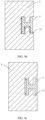
- FIG. 1 and FIG. 2 are schematic diagrams of an assembly state of an adhesive component and a waterproof component in a housing structure of a current terminal. It should be noted that in the schematic diagrams of the assembly state in FIG. 1 and FIG. 2 , only the adhesive component and the waterproof component are shown, and another component is omitted.
- the waterproof component shown in FIG. 1 and FIG. 2 is in a basic geometric shape such as a square and a trapezoid. If this conventional adhesive component and waterproof component are used, external liquid is likely to enter the terminal, resulting in a relatively poor waterproof effect.
- a provided terminal device may be any terminal such as a mobile phone, a wearable device, an AR (Augmented Reality, augmented reality)/VR (Virtual Reality, virtual reality) device, a tablet computer, a notebook computer, a UMPC (Ultra-mobile Personal Computer, ultra-mobile personal computer), a netbook, or a PDA (Personal Digital Assistant, personal digital assistant). This is not limited in the embodiments of this application.
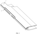
- FIG. 3 is a schematic diagram of a housing structure of a terminal in a closed state according to an embodiment of this application.
- the housing structure includes a battery cover 1 and a middle frame 2, and the battery cover 1 is connected to the middle frame 2.
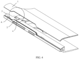
- FIG. 4 is a schematic diagram of a housing structure in an open state according to an embodiment of this application
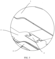
- FIG. 5 is an enlarged schematic diagram of a region A in FIG. 4 .
- the housing structure includes not only all components in FIG. 1 but also an adhesive component 3.
- the battery cover 1 is connected to the middle frame 2 by using the adhesive component 3, for example, may be connected to the middle frame 2 by using adhesive.
- the battery cover 1 is connected to the middle frame 2, in other words, the housing structure is in the closed state.
- the housing structure sequentially including the battery cover 1, the adhesive component 3, and the middle frame 2 from top to bottom.
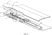
- FIG. 6 is an exploded schematic diagram of a terminal according to an embodiment of this application
- FIG. 7 is an enlarged schematic diagram of a region B in FIG. 6
- a hole is disposed at a local position of the middle frame 2 for placing a key FPC.
- a support wall 21 protruding in a direction of the battery cover 1 is disposed on the middle frame 2, and the key FPC is bent from the support wall 21.
- an opening groove is disposed on a top of the support wall 21.
- a top of the support wall 21 sinks, that is, a specific avoidance distance is set between the top of the support wall 21 and the battery cover 1. Consequently, there is a gap between the top of the support wall 21 and the battery cover 1, and external water vapor is likely to enter the terminal through the gap. Therefore, a waterproof structure needs to be disposed at the gap, to improve a waterproof effect.
- a waterproof component 4 may be further disposed at the gap between the top of the support wall 21 and the battery cover 1.
- an opening groove 31 is further disposed on the adhesive component 3.
- a cross-sectional shape of the opening groove 31 is adapted to a shape of the waterproof component 4.
- an avoidance distance is set between the adhesive component 3 and the waterproof component 4.
- the adhesive component 3 and the waterproof component 4 form the waterproof structure in the embodiments of this application, and the avoidance distance between the adhesive component 3 and the waterproof component 4 forms a liquid inlet path.
- the key FPC interferes with the adhesive component 3.
- the battery cover 1 is warped after being assembled, or the battery cover 1 is likely to come unglued after being used for a long time.
- the key FPC pushes up the battery cover, and for a special battery cover 1, an indentation is shown. Consequently, user experience is affected.
- the opening groove 31 may further prevent the adhesive component 3 from being bonded to the key FPC. When the adhesive component 3 is bonded to the key FPC, and the battery cover 1 slightly moves, the key FPC is likely to be damaged by pulling of the adhesive component 3, and consequently performance is affected.
- FIG. 8 is a schematic diagram of an assembly state of an adhesive component 3 and a waterproof component 4 according to the first embodiment of this application. It should be noted that in FIG. 8 , only the adhesive component 3 and the waterproof component 4 are shown, and another component is omitted. In the embodiment shown in FIG. 8 , there is a concave structure on a first side or a second side of a cross section of the waterproof component 4. In the embodiment shown in FIG. 8 , the first side and the second side of the cross section of the waterproof component 4 are not on a same side as an opening of an opening groove 31, and are not opposite to the opening of the opening groove 31.
- the waterproof component 4 and the adhesive component 3 are normally mounted. After entering a waterproof structure from the outside, liquid flows along a gap between the waterproof component 4 and the adhesive component 3. In this case, all gaps between the waterproof component 4 and the adhesive component 3 communicate with each other.
- the concave structure on the first side or the second side in FIG. 8 may further store the liquid.
- the liquid When the waterproof component 4 and the adhesive component 3 are normally mounted, after entering the waterproof structure from the outside, the liquid enters from an inlet of a liquid inlet path on the first side or the second side, then passes through the concave structure on the first side or the second side, and finally flows out from an outlet. Therefore, the added concave structure can significantly extend the liquid inlet path, to decrease a liquid inlet speed. In addition, after entering the concave structure along the liquid inlet path, the liquid is stored in the concave structure. Therefore, the liquid can be restricted, to some extent, from entering a terminal.
- the liquid inlet path can also be extended, the liquid inlet speed can be decreased, and liquid can be stored. Therefore, the liquid is restricted, to some extent, from entering the terminal. Finally, in comparison with the conventional waterproof structure, a waterproof effect is improved.
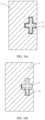
- FIG. 9a to FIG. 9e are schematic diagrams of an assembly state of an adhesive component 3 and a waterproof component 4 according to the second embodiment of this application. It should be noted that in FIG. 9a to FIG. 9e , only the adhesive component 3 and the waterproof component 4 are shown, and another component is omitted. In the embodiment shown in FIG. 9a to FIG. 9e , there is a concave structure on each of a first side and a second side of a cross section of the waterproof component 4. In the embodiment shown in FIG. 9a to FIG. 9e , the first side and the second side of the cross section of the waterproof component 4 are not on a same side as an opening of an opening groove 31, and are not opposite to the opening of the opening groove 31. Therefore, actually, in the embodiment shown in FIG. 9a to FIG. 9e , the cross section of the waterproof component 4 is H-shaped.
- FIG. 9a is a schematic diagram of a state in which the waterproof component 4 whose cross section is H-shaped and the adhesive component 3 are normally mounted, in other words, the waterproof component 4 and the adhesive component 3 are not deviated during mounting.
- FIG. 9a after entering a waterproof structure from the outside, liquid flows along a gap between the waterproof component 4 and the opening groove 31. In this case, all gaps between the waterproof component 4 and the opening groove 31 communicate with each other.
- There is the concave structure on each of the first side and the second side and therefore in comparison with a conventional waterproof structure (as shown in FIG. 1 and FIG. 2 ), a liquid inlet path in FIG. 9a is longer than that of the conventional waterproof structure.
- the concave structure on each of the first side and the second side in FIG. 9a may further store the liquid.
- FIG. 9b is a schematic diagram of a state in which the waterproof component 4 whose cross section is H-shaped is deviated upward during attachment.
- the liquid can flow only along a bottom gap between the waterproof component 4 and the opening groove 31 because a top gap between the waterproof component 4 and the opening groove 31 is closed.
- a liquid inlet path in FIG. 9b is still longer than that of the conventional waterproof structure, and a concave structure at a bottom may still store the liquid.
- FIG. 9c is a schematic diagram of a state in which the waterproof component 4 whose cross section is H-shaped is deviated to the right during attachment.
- a liquid inlet path on the first side is closed because a side wall of the concave structure on the first side is in contact with a side wall of the opening groove 31.
- a side wall of the concave structure on the second side is in contact with the side wall of the opening groove 31, and therefore a liquid inlet path on the second side is closed.
- the liquid can no longer flow along a gap between the waterproof component 4 and the opening groove 31. Therefore, in the embodiment shown in FIG. 9c , when the waterproof component 4 is deviated to the right during attachment, the liquid can be completely restricted from entering a terminal.
- FIG. 9d is a schematic diagram of a state in which the waterproof component 4 whose cross section is H-shaped is deviated to the left during attachment.
- a liquid inlet path on the first side is closed because a side wall of the concave structure on the first side is in contact with a side wall of the opening groove 31.
- a side wall of the concave structure on the second side is in contact with the side wall of the opening groove 31, and therefore a liquid inlet path on the second side is closed.
- the liquid inlet path on each of the first side and the second side is closed, the liquid can flow a specific distance along a gap between the waterproof component 4 and the opening groove 31, but still cannot flow into a terminal. Therefore, in the embodiment shown in FIG. 9d , when the waterproof component 4 is deviated to the left during attachment, the liquid can also be completely restricted from entering the terminal.
- FIG. 9e is a schematic diagram of a state in which the waterproof component 4 whose cross section is H-shaped is rotationally deviated during attachment.
- a liquid inlet path on the first side is closed because a vertex of a side wall of the concave structure on the first side is in contact with a side wall of the opening groove 31.
- a vertex of a side wall of the concave structure on the second side is in contact with the side wall of the opening groove 31, and therefore a liquid inlet path on the second side is closed.
- the liquid inlet path on each of the first side and the second side is closed, the liquid can flow a specific distance along a gap between the waterproof component 4 and the opening groove 31, but still cannot flow into a terminal. Therefore, in the embodiment shown in FIG. 9e , when the waterproof component 4 is rotationally deviated during attachment, the liquid can also be completely restricted from entering the terminal.
- the technical solutions provided in the second embodiment of this application have the following beneficial effects: First, if the waterproof component 4 and the opening groove 31 are in the state of being normally mounted, after entering the waterproof structure from the outside, the liquid enters from an inlet of the liquid inlet path on the first side, then passes through the concave structure on the first side, and finally flows out from an outlet. Therefore, the added concave structure can significantly extend the liquid inlet path, to decrease a liquid inlet speed. Similarly, the liquid further enters from an inlet of the liquid inlet path on the second side, then passes through the concave structure on the second side, and finally flows out from an outlet. Therefore, the added concave structure can also significantly extend the liquid inlet path, to decrease the liquid inlet speed.
- a waterproof effect of the terminal is improved in terms of decreasing the liquid inlet speed.
- the liquid after entering the concave structure on each of the first side and the second side along the liquid inlet path, the liquid is stored in the concave structure, and therefore the liquid can be restricted, to some extent, from entering the terminal.
- the waterproof effect of the terminal is improved in terms of liquid storage.
- the added concave structure can still extend a liquid inlet path on the other side, and overall the liquid inlet speed can still be decreased. If the waterproof component 4 is in the state of being deviated to the left or to the right during attachment, the liquid inlet path on each of the first side and the second side can be completely closed, and therefore the liquid can be completely restricted from entering the terminal. If the waterproof component 4 is rotationally deviated during attachment, the liquid inlet path on each of the first side and the second side is also closed, and therefore the liquid can also be completely restricted from entering the terminal.
- the waterproof effect of the terminal can be improved in terms of decreasing the liquid inlet speed and liquid storage.
- the waterproof component 4 when the waterproof component 4 is in the state of being deviated to the left during attachment, the state of being deviated to the right during attachment, and the state of being rotationally deviated during attachment, the liquid can be completely restricted from entering the terminal. In this way, regardless of a mounting state of the waterproof component 4 and the adhesive component 3, the waterproof effect of the terminal can be improved.
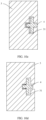
- FIG. 10a to FIG. 10e are schematic diagrams of an assembly state of an adhesive component 3 and a waterproof component 4 according to the third embodiment of this application. It should be noted that in FIG. 10a to FIG. 10e , only the adhesive component 3 and the waterproof component 4 are shown, and another component is omitted. In the embodiment shown in FIG. 10a to FIG. 10e , there is a convex structure on each of a first side and a second side of a cross section of the waterproof component 4. In the embodiment shown in FIG. 10a to FIG. 10e , the first side and the second side of the cross section of the waterproof component 4 are not on a same side as an opening of an opening groove 31, and are not opposite to the opening of the opening groove 31. Therefore, actually, in the embodiment shown in FIG. 10a to FIG. 10e , the cross section of the waterproof component 4 is cross-shaped.
- FIG. 10a is a schematic diagram of a state in which the waterproof component 4 whose cross section is cross-shaped and the adhesive component 3 are normally mounted, in other words, the waterproof component 4 and the adhesive component 3 are not deviated during mounting.
- FIG. 10a after entering a waterproof structure from the outside, liquid flows along a gap between the waterproof component 4 and the opening groove 31. In this case, all gaps between the waterproof component 4 and the opening groove 31 communicate with each other.
- There is the convex structure on each of the first side and the second side and therefore in comparison with a conventional waterproof structure (as shown in FIG. 1 and FIG. 2 ), a liquid inlet path in FIG. 10a is longer than that of the conventional waterproof structure.
- the convex structure on each of the first side and the second side in FIG. 10a may further store the liquid.
- FIG. 10b is a schematic diagram of a state in which the waterproof component 4 whose cross section is cross-shaped is deviated upward during attachment.
- the liquid can flow only along a bottom gap between the waterproof component 4 and the opening groove 31 because a top gap between the waterproof component 4 and the opening groove 31 is closed.
- a liquid inlet path in FIG. 10b is still longer than that of the conventional waterproof structure, and a convex structure at a bottom may still store the liquid.
- FIG. 10c is a schematic diagram of a state in which the waterproof component 4 whose cross section is cross-shaped is deviated to the right during attachment.
- a liquid inlet path on the first side is closed because a side wall of the convex structure on the first side is in contact with a side wall of the opening groove 31.
- a side wall of the convex structure on the second side is in contact with the side wall of the opening groove 31, and therefore a liquid inlet path on the second side is closed.
- the liquid can no longer flow along a gap between the waterproof component 4 and the opening groove 31. Therefore, in the embodiment shown in FIG. 10c , when the waterproof component 4 is deviated to the right during attachment, the liquid can be completely restricted from entering a terminal.
- FIG. 10d is a schematic diagram of a state in which the waterproof component 4 whose cross section is cross-shaped is deviated to the left during attachment.
- a liquid inlet path on the first side is closed because a side wall of the convex structure on the first side is in contact with a side wall of the opening groove 31.
- a side wall of the convex structure on the second side is in contact with the side wall of the opening groove 31, and therefore a liquid inlet path on the second side is closed.
- the liquid inlet path on each of the first side and the second side is closed, the liquid can flow a specific distance along a gap between the waterproof component 4 and the opening groove 31, but still cannot flow into a terminal. Therefore, in the embodiment shown in FIG. 10d , when the waterproof component 4 is deviated to the left during attachment, the liquid can also be completely restricted from entering the terminal.
- FIG. 10e is a schematic diagram of a state in which the waterproof component 4 whose cross section is cross-shaped is rotationally deviated during attachment.
- a liquid inlet path on the first side is closed because a vertex of a side wall of the convex structure on the first side is in contact with a side wall of the opening groove 31.
- a vertex of a side wall of the convex structure on the second side is in contact with the side wall of the opening groove 31, and therefore a liquid inlet path on the second side is closed.
- the liquid inlet path on each of the first side and the second side is closed, the liquid can flow a specific distance along a gap between the waterproof component 4 and the opening groove 31, but still cannot flow into a terminal. Therefore, in the embodiment shown in FIG. 10e , when the waterproof component 4 is rotationally deviated during attachment, the liquid can also be completely restricted from entering the terminal.
- the technical solutions provided in the third embodiment of this application have the following beneficial effects: First, if the waterproof component 4 and the opening groove 31 are in the state of being normally mounted, after entering the waterproof structure from the outside, the liquid enters from an inlet of the liquid inlet path on the first side, then passes through the convex structure on the first side, and finally flows out from an outlet. Therefore, the added convex structure can significantly extend the liquid inlet path, to decrease a liquid inlet speed. Similarly, the liquid further enters from an inlet of the liquid inlet path on the second side, then passes through the convex structure on the second side, and finally flows out from an outlet. Therefore, the added convex structure can also significantly extend the liquid inlet path, to decrease the liquid inlet speed.
- a waterproof effect of the terminal is improved in terms of decreasing the liquid inlet speed.
- the liquid after entering the convex structure on each of the first side and the second side along the liquid inlet path, the liquid is stored in the convex structure, and therefore the liquid can be restricted, to some extent, from entering the terminal.
- the waterproof effect of the terminal is improved in terms of liquid storage.
- the waterproof component 4 is in the state of being deviated upward or downward during attachment, when a liquid inlet path on one side is closed, the added convex structure can still extend a liquid inlet path on the other side, and overall the liquid inlet speed can still be decreased.
- the liquid inlet path on each of the first side and the second side can be completely closed, and therefore the liquid can be completely restricted from entering the terminal.
- the liquid inlet path on each of the first side and the second side is also closed, and therefore the liquid can also be completely restricted from entering the terminal.
- the waterproof effect of the terminal can be improved in terms of decreasing the liquid inlet speed and liquid storage.
- the waterproof component 4 when the waterproof component 4 is in the state of being deviated to the left during attachment, the state of being deviated to the right during attachment, and the state of being rotationally deviated during attachment, the liquid can be completely restricted from entering the terminal. In this way, regardless of a mounting state of the waterproof component 4 and the adhesive component 3, the waterproof effect of the terminal can be improved.
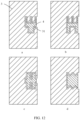
- FIG. 11a to FIG. 11e are schematic diagrams of an assembly state of an adhesive component and a waterproof component in a housing structure of a terminal according to a fourth embodiment of this application.
- FIG. 11a is a schematic diagram of a state in which the waterproof component 4 and the adhesive component 3 are normally mounted. If the waterproof component 4 and the adhesive component 3 are in a state of being normally mounted, the concave structure and the convex structure extend a liquid inlet path, to decrease a liquid inlet speed. In addition, the concave structure and the convex structure can store liquid, and therefore the liquid is restricted, to some extent, from continuing to enter the terminal. A specific implementation principle is consistent with those in the second embodiment and the third embodiment. Details are not described in this embodiment.
- FIG. 11b is a schematic diagram of a mounting state in which the waterproof component 4 is deviated upward during attachment. If the waterproof component 4 is in a mounting state of being deviated upward or downward during attachment, the concave structure and the convex structure extend a liquid inlet path, to decrease a liquid inlet speed. In addition, the concave structure and the convex structure can store liquid, and therefore the liquid is restricted, to some extent, from continuing to enter the terminal. A specific implementation principle is consistent with those in the second embodiment and the third embodiment. Details are not described in this embodiment.
- FIG. 11c is a schematic diagram of a mounting state in which the waterproof component 4 is deviated to the left during attachment
- FIG. 11d is a schematic diagram of a mounting state in which the waterproof component 4 is deviated to the right during attachment
- FIG. 11e is a schematic diagram of a mounting state in which the waterproof component 4 is rotationally deviated during attachment. If the waterproof component 4 is in one of the mounting state of being deviated to the left during attachment, the mounting state of being deviated to the right during attachment, and the mounting state of being rotationally deviated during attachment, liquid can be completely restricted from entering the terminal.
- a specific implementation principle is consistent with those in the second embodiment and the third embodiment. Details are not described in this embodiment.
- FIG. 12 is a schematic diagram of an assembly state of an adhesive component and a waterproof component in a housing structure of a terminal according to a fifth embodiment to an eighth embodiment of this application.
- the fifth embodiment shown in (a) in FIG. 12 there are two concave structures on a first side of a cross section of the waterproof component 4, and there is one convex structure on a second side.
- a sixth embodiment shown in (b) in FIG. 12 there are two concave structures on a first side of a cross section of the waterproof component 4, and there is one convex structure on a second side.
- a width of a liquid inlet path between the waterproof component 4 and an opening groove 31 always remains unchanged, in other words, a width of a gap between the waterproof component 4 and the opening groove 31 always remains unchanged. In this way, during mounting, regardless of whether the waterproof component 4 is deviated to the left or to the right during attachment, it can be ensured that a liquid inlet path on each of the first side and the second side is closed, to ensure that liquid is completely restricted from entering the terminal.
- liquid inlet path may be completely closed when the waterproof component in the current terminal shown in FIG. 1 and FIG. 2 is rotationally deviated during attachment and even the liquid inlet path is completely closed when the trapezoidal waterproof component shown in FIG. 2 is deviated to the right during attachment, it may be learned that in comparison with this embodiment of this application, it is more difficult to completely close the liquid inlet path by using the waterproof component in the current terminal.
- the trapezoidal waterproof component in FIG. 2 needs to be deviated to the right for a relatively long distance during attachment, to completely close the liquid inlet path.
- the liquid inlet path can be extended, a liquid inlet speed can be decreased, and liquid can be stored.
- FIG. 13 is a schematic diagram of an assembly state of an adhesive component 3 and a waterproof component 4 according to an eighth embodiment of this application. It should be noted that in FIG. 13 , only the adhesive component 3 and the waterproof component 4 are shown, and another component is omitted. In the embodiment shown in FIG. 13 , there is a concave structure on each of a first side and a second side of a cross section of the waterproof component 4. In addition, there is also a concave structure on a third side of the cross section of the waterproof component 4. The third side shown in FIG. 13 is opposite to an opening of an opening groove 31. In the embodiment shown in FIG. 13 , the waterproof component 4 and the adhesive component 3 are in a state of being normally mounted.
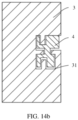
- FIG. 14a and FIG. 14b are schematic diagrams of an assembly state of an adhesive component 3 and a waterproof component 4 according to the tenth embodiment of this application. It should be noted that in FIG. 14a and FIG. 14b , only the adhesive component 3 and the waterproof component 4 are shown, and another component is omitted. In the embodiment shown in FIG. 14a and FIG. 14b , there is a concave structure on each of a first side and a second side of a cross section of the waterproof component 4. In addition, there is also a concave structure on each of a third side and a fourth side of the cross section of the waterproof component 4. The fourth side shown in FIG. 14a and FIG. 14b is on a same side as an opening groove 31. FIG.
- the liquid can be completely restricted from flowing into the terminal only when the waterproof component 4 is deviated to the left or to the right during attachment.
- the liquid can be completely restricted from flowing into the terminal when the waterproof component 4 is deviated to the left or to the right during attachment, and the liquid can be completely restricted from flowing into the terminal when the waterproof component 4 is deviated upward or downward during attachment.
- the waterproof component 4 After a middle frame 2 and a battery cover 1 are assembled, a smaller area of the waterproof component 4 indicates smaller push force generated for the battery cover 1, to reduce a risk that the battery cover 1 comes unglued.
- the waterproof component 4 may be in a shape such as a parallelogram, a triangle, or a circle.
Landscapes
- Engineering & Computer Science (AREA)
- Chemical & Material Sciences (AREA)
- Chemical Kinetics & Catalysis (AREA)
- Electrochemistry (AREA)
- General Chemical & Material Sciences (AREA)
- Microelectronics & Electronic Packaging (AREA)
- Signal Processing (AREA)
- Life Sciences & Earth Sciences (AREA)
- Biophysics (AREA)
- Computer Hardware Design (AREA)
- Casings For Electric Apparatus (AREA)
- Connector Housings Or Holding Contact Members (AREA)
Claims (9)
- Endgerät, wobei das Endgerät Folgendes umfasst: eine Batterieabdeckung (1), einen mittleren Rahmen (2), eine Klebstoffkomponente (3) und eine wasserfeste Komponente (4) ;wobei die Batterieabdeckung (1) unter Verwendung der Klebstoffkomponente (3) am mittleren Rahmen (2) angeklebt ist;wobei eine Stützwand (21), die in einer Richtung der Batterieabdeckung (1) herausragt, am mittleren Rahmen (2) angeordnet ist;wobei die Klebstoffkomponente (3) mit einer Öffnungsnut (31) versehen ist und die Öffnungsnut (31) eine halbgeschlossene Nut ist;wobei die wasserfeste Komponente (4) zwischen der Stützwand (21) und der Klebstoffkomponente (3) angeordnet ist und in der Öffnungsnut (31) befindlich ist;wobei eine Querschnittsform der wasserfesten Komponente (4) an eine Querschnittsform der Öffnungsnut (31) angepasst ist, wobei es einen Vermeidungsabstand zwischen der wasserfesten Komponente (4) und der Öffnungsnut (31) gibt und wobei ein Flüssigkeitseinlasspfad gebildet wird; undwobei ein Querschnitt der wasserfesten Komponente (4) an zumindest einer aus einer ersten Seite und einer zweiten Seite eine konvexe Struktur oder eine konkave Struktur aufweist, und wobei die erste Seite und die zweite Seite nicht auf einer gleichen Seite wie eine Öffnung der Öffnungsnut (31) sind und nicht gegenüberliegend zur Öffnung der Öffnungsnut (31) sind.
- Endgerät nach Anspruch 1, wobei der Querschnitt der wasserfesten Komponente (4) auf jeder aus der ersten Seite und der zweiten Seite die konvexe Struktur oder die konkave Struktur aufweist.
- Endgerät nach Anspruch 2, wobei, wenn eine Seitenwand von zumindest einer konvexen Struktur oder konkaven Struktur auf der ersten Seite in Kontakt mit einer entsprechenden Seitenwand der Öffnungsnut (31) ist, eine Seitenwand von zumindest einer konvexen Struktur oder konkaven Struktur auf der zweiten Seite in Kontakt mit der entsprechenden Seitenwand der Öffnungsnut (31) ist.
- Endgerät nach Anspruch 2, wobei der Querschnitt der wasserfesten Komponente (4) auf zumindest einer aus einer dritten Seite und einer vierten Seite die konvexe Struktur oder die konkave Struktur aufweist, wobei die dritte Seite auf einer gleichen Seite wie die Öffnung der Öffnungsnut (31) ist und die vierte Seite gegenüberliegend zur Öffnung der Öffnungsnut (31) ist.
- Endgerät nach Anspruch 4, wobei der Querschnitt der wasserfesten Komponente (4) auf jeder aus der dritten Seite und der vierten Seite die konvexe Struktur oder die konkave Struktur aufweist.
- Endgerät nach Anspruch 5, wobei, wenn eine Seitenwand von zumindest einer konvexen Struktur oder konkaven Struktur auf der dritten Seite in Kontakt mit einer entsprechenden Seitenwand der Öffnungsnut (31) ist, eine Seitenwand von zumindest einer konvexen Struktur oder konkaven Struktur auf der vierten Seite in Kontakt mit der entsprechenden Seitenwand der Öffnungsnut (31) ist.
- Endgerät nach Anspruch 2, wobei, wenn eine mittlere Achse der wasserfesten Komponente nicht parallel zu einer mittleren Achse der Öffnungsnut (31) ist und ein Scheitelpunkt zumindest einer konvexen Struktur oder konkaven Struktur auf der ersten Seite in Kontakt mit einer entsprechenden Seitenwand der Öffnungsnut (31) ist, ein Scheitelpunkt zumindest einer konvexen Struktur oder konkaven Struktur auf der zweiten Seite in Kontakt mit der entsprechenden Seitenwand der Öffnungsnut (31) ist.
- Endgerät nach einem der Ansprüche 1 bis 7, wobei der Querschnitt der wasserfesten Komponente (4) H-förmig oder kreuzförmig ist.
- Endgerät nach einem der Ansprüche 1 bis 7, wobei die wasserfeste Komponente (4) aus einem zusammendrückbaren wasserfesten Material gefertigt ist.
Applications Claiming Priority (2)
| Application Number | Priority Date | Filing Date | Title |
|---|---|---|---|
| CN202110908070.7A CN114497859B (zh) | 2021-08-09 | 2021-08-09 | 一种终端 |
| PCT/CN2022/087935 WO2023015934A1 (zh) | 2021-08-09 | 2022-04-20 | 一种终端 |
Publications (3)
| Publication Number | Publication Date |
|---|---|
| EP4184904A1 EP4184904A1 (de) | 2023-05-24 |
| EP4184904A4 EP4184904A4 (de) | 2024-03-06 |
| EP4184904B1 true EP4184904B1 (de) | 2024-12-11 |
Family
ID=81491795
Family Applications (1)
| Application Number | Title | Priority Date | Filing Date |
|---|---|---|---|
| EP22854938.2A Active EP4184904B1 (de) | 2021-08-09 | 2022-04-20 | Endgerät |
Country Status (4)
| Country | Link |
|---|---|
| US (1) | US12477671B2 (de) |
| EP (1) | EP4184904B1 (de) |
| CN (1) | CN114497859B (de) |
| WO (1) | WO2023015934A1 (de) |
Family Cites Families (16)
| Publication number | Priority date | Publication date | Assignee | Title |
|---|---|---|---|---|
| JP2014068054A (ja) * | 2012-09-24 | 2014-04-17 | Sharp Corp | 携帯端末 |
| KR102094754B1 (ko) * | 2013-12-03 | 2020-03-30 | 엘지전자 주식회사 | 이동 단말기 |
| CN104506674B (zh) | 2014-12-02 | 2018-01-23 | 广东欧珀移动通信有限公司 | 手机密封结构及终端 |
| WO2017065397A1 (ko) | 2015-10-16 | 2017-04-20 | 삼성전자 주식회사 | 전자장치 및 전자장치 제조방법 |
| KR102497472B1 (ko) * | 2016-07-29 | 2023-02-08 | 삼성전자주식회사 | 방수 구조를 포함하는 전자 장치 |
| CN106847588B (zh) * | 2017-03-30 | 2019-10-08 | 努比亚技术有限公司 | 一种防水侧按键装置及其组装方法、移动终端 |
| KR102308940B1 (ko) * | 2017-04-21 | 2021-10-05 | 삼성전자주식회사 | 방수 구조를 포함하는 전자 장치 |
| CN207117686U (zh) | 2017-04-27 | 2018-03-16 | 维沃移动通信有限公司 | 一种移动终端 |
| CN207720209U (zh) * | 2018-01-16 | 2018-08-10 | 威海网时代电子科技有限公司 | 一种三防手机密封防水结构 |
| CN109167862A (zh) * | 2018-11-26 | 2019-01-08 | 青岛海信移动通信技术股份有限公司 | 移动终端 |
| CN209151206U (zh) | 2019-01-28 | 2019-07-23 | 珠海市魅族科技有限公司 | 一种移动终端及其中框 |
| JP7286998B2 (ja) * | 2019-02-25 | 2023-06-06 | 沖電気工業株式会社 | 電子機器筐体 |
| KR102819731B1 (ko) * | 2020-05-21 | 2025-06-12 | 삼성전자 주식회사 | 음향 모듈을 포함하는 전자 장치 |
| CN212727130U (zh) * | 2020-08-31 | 2021-03-16 | 北京小米移动软件有限公司 | 移动终端侧键结构和终端 |
| EP4192212A4 (de) * | 2021-01-27 | 2024-03-27 | Samsung Electronics Co., Ltd. | Elektronische vorrichtung mit dichtungselement |
| CN113096990B (zh) * | 2021-03-05 | 2022-07-08 | 北京小米移动软件有限公司 | 移动终端侧键结构和终端 |
-
2021
- 2021-08-09 CN CN202110908070.7A patent/CN114497859B/zh active Active
-
2022
- 2022-04-20 WO PCT/CN2022/087935 patent/WO2023015934A1/zh not_active Ceased
- 2022-04-20 US US18/043,540 patent/US12477671B2/en active Active
- 2022-04-20 EP EP22854938.2A patent/EP4184904B1/de active Active
Also Published As
| Publication number | Publication date |
|---|---|
| WO2023015934A1 (zh) | 2023-02-16 |
| CN114497859B (zh) | 2022-12-16 |
| EP4184904A1 (de) | 2023-05-24 |
| CN114497859A (zh) | 2022-05-13 |
| US12477671B2 (en) | 2025-11-18 |
| EP4184904A4 (de) | 2024-03-06 |
| US20240407109A1 (en) | 2024-12-05 |
Similar Documents
| Publication | Publication Date | Title |
|---|---|---|
| EP3729991B1 (de) | Gehäusestruktur | |
| CN102573348B (zh) | 电子装置 | |
| CN115701703A (zh) | 一种可折叠设备和防护器件 | |
| JP2010067730A (ja) | 緩衝構造 | |
| CN108600418B (zh) | 电子装置及其制造方法 | |
| US9055206B1 (en) | Electronic device | |
| EP4287593B1 (de) | Elektronische vorrichtung | |
| EP4184904B1 (de) | Endgerät | |
| CN201583869U (zh) | 笔记本电脑的显示器 | |
| JP5544622B2 (ja) | 電子デバイス | |
| CN219873255U (zh) | 一种电子设备 | |
| CN110389626A (zh) | 电子设备 | |
| EP4207723A1 (de) | Elektronische vorrichtung | |
| CN101770254A (zh) | 笔记本电脑及其卡合机构 | |
| CN110557483A (zh) | 一种伸缩机构及移动终端 | |
| HK40069246B (en) | Terminal | |
| CN204335204U (zh) | 终端 | |
| CN111601029A (zh) | 摄像头模组及电子设备 | |
| CN112736360A (zh) | 一种电池结构及电子设备 | |
| CN221804669U (zh) | 一种键盘 | |
| CN111131587B (zh) | 电子设备及其装配方法 | |
| CN217239041U (zh) | 一种抗摔防震型固态硬盘套件 | |
| CN217333055U (zh) | 显示组件 | |
| JP7839976B2 (ja) | 電子機器 | |
| CN101739068A (zh) | 电子装置的上机体构造 |
Legal Events
| Date | Code | Title | Description |
|---|---|---|---|
| STAA | Information on the status of an ep patent application or granted ep patent |
Free format text: STATUS: THE INTERNATIONAL PUBLICATION HAS BEEN MADE |
|
| PUAI | Public reference made under article 153(3) epc to a published international application that has entered the european phase |
Free format text: ORIGINAL CODE: 0009012 |
|
| STAA | Information on the status of an ep patent application or granted ep patent |
Free format text: STATUS: REQUEST FOR EXAMINATION WAS MADE |
|
| 17P | Request for examination filed |
Effective date: 20230220 |
|
| AK | Designated contracting states |
Kind code of ref document: A1 Designated state(s): AL AT BE BG CH CY CZ DE DK EE ES FI FR GB GR HR HU IE IS IT LI LT LU LV MC MK MT NL NO PL PT RO RS SE SI SK SM TR |
|
| A4 | Supplementary search report drawn up and despatched |
Effective date: 20240205 |
|
| RIC1 | Information provided on ipc code assigned before grant |
Ipc: H01M 50/247 20210101ALI20240130BHEP Ipc: H01M 50/271 20210101ALI20240130BHEP Ipc: H04M 1/18 20060101ALI20240130BHEP Ipc: H04M 1/02 20060101ALI20240130BHEP Ipc: H01H 13/06 20060101ALI20240130BHEP Ipc: H04M 1/23 20060101AFI20240130BHEP |
|
| GRAP | Despatch of communication of intention to grant a patent |
Free format text: ORIGINAL CODE: EPIDOSNIGR1 |
|
| STAA | Information on the status of an ep patent application or granted ep patent |
Free format text: STATUS: GRANT OF PATENT IS INTENDED |
|
| DAV | Request for validation of the european patent (deleted) | ||
| DAX | Request for extension of the european patent (deleted) | ||
| INTG | Intention to grant announced |
Effective date: 20240710 |
|
| GRAS | Grant fee paid |
Free format text: ORIGINAL CODE: EPIDOSNIGR3 |
|
| GRAA | (expected) grant |
Free format text: ORIGINAL CODE: 0009210 |
|
| STAA | Information on the status of an ep patent application or granted ep patent |
Free format text: STATUS: THE PATENT HAS BEEN GRANTED |
|
| AK | Designated contracting states |
Kind code of ref document: B1 Designated state(s): AL AT BE BG CH CY CZ DE DK EE ES FI FR GB GR HR HU IE IS IT LI LT LU LV MC MK MT NL NO PL PT RO RS SE SI SK SM TR |
|
| REG | Reference to a national code |
Ref country code: GB Ref legal event code: FG4D |
|
| REG | Reference to a national code |
Ref country code: CH Ref legal event code: EP |
|
| REG | Reference to a national code |
Ref country code: DE Ref legal event code: R096 Ref document number: 602022008683 Country of ref document: DE |
|
| REG | Reference to a national code |
Ref country code: IE Ref legal event code: FG4D |
|
| REG | Reference to a national code |
Ref country code: LT Ref legal event code: MG9D |
|
| PG25 | Lapsed in a contracting state [announced via postgrant information from national office to epo] |
Ref country code: HR Free format text: LAPSE BECAUSE OF FAILURE TO SUBMIT A TRANSLATION OF THE DESCRIPTION OR TO PAY THE FEE WITHIN THE PRESCRIBED TIME-LIMIT Effective date: 20241211 |
|
| PG25 | Lapsed in a contracting state [announced via postgrant information from national office to epo] |
Ref country code: FI Free format text: LAPSE BECAUSE OF FAILURE TO SUBMIT A TRANSLATION OF THE DESCRIPTION OR TO PAY THE FEE WITHIN THE PRESCRIBED TIME-LIMIT Effective date: 20241211 |
|
| PG25 | Lapsed in a contracting state [announced via postgrant information from national office to epo] |
Ref country code: BG Free format text: LAPSE BECAUSE OF FAILURE TO SUBMIT A TRANSLATION OF THE DESCRIPTION OR TO PAY THE FEE WITHIN THE PRESCRIBED TIME-LIMIT Effective date: 20241211 |
|
| REG | Reference to a national code |
Ref country code: NL Ref legal event code: MP Effective date: 20241211 |
|
| PG25 | Lapsed in a contracting state [announced via postgrant information from national office to epo] |
Ref country code: ES Free format text: LAPSE BECAUSE OF FAILURE TO SUBMIT A TRANSLATION OF THE DESCRIPTION OR TO PAY THE FEE WITHIN THE PRESCRIBED TIME-LIMIT Effective date: 20241211 |
|
| PG25 | Lapsed in a contracting state [announced via postgrant information from national office to epo] |
Ref country code: NO Free format text: LAPSE BECAUSE OF FAILURE TO SUBMIT A TRANSLATION OF THE DESCRIPTION OR TO PAY THE FEE WITHIN THE PRESCRIBED TIME-LIMIT Effective date: 20250311 |
|
| PG25 | Lapsed in a contracting state [announced via postgrant information from national office to epo] |
Ref country code: GR Free format text: LAPSE BECAUSE OF FAILURE TO SUBMIT A TRANSLATION OF THE DESCRIPTION OR TO PAY THE FEE WITHIN THE PRESCRIBED TIME-LIMIT Effective date: 20250312 Ref country code: LV Free format text: LAPSE BECAUSE OF FAILURE TO SUBMIT A TRANSLATION OF THE DESCRIPTION OR TO PAY THE FEE WITHIN THE PRESCRIBED TIME-LIMIT Effective date: 20241211 |
|
| PG25 | Lapsed in a contracting state [announced via postgrant information from national office to epo] |
Ref country code: RS Free format text: LAPSE BECAUSE OF FAILURE TO SUBMIT A TRANSLATION OF THE DESCRIPTION OR TO PAY THE FEE WITHIN THE PRESCRIBED TIME-LIMIT Effective date: 20250311 |
|
| PG25 | Lapsed in a contracting state [announced via postgrant information from national office to epo] |
Ref country code: NL Free format text: LAPSE BECAUSE OF FAILURE TO SUBMIT A TRANSLATION OF THE DESCRIPTION OR TO PAY THE FEE WITHIN THE PRESCRIBED TIME-LIMIT Effective date: 20241211 |
|
| REG | Reference to a national code |
Ref country code: AT Ref legal event code: MK05 Ref document number: 1751278 Country of ref document: AT Kind code of ref document: T Effective date: 20241211 |
|
| PG25 | Lapsed in a contracting state [announced via postgrant information from national office to epo] |
Ref country code: SM Free format text: LAPSE BECAUSE OF FAILURE TO SUBMIT A TRANSLATION OF THE DESCRIPTION OR TO PAY THE FEE WITHIN THE PRESCRIBED TIME-LIMIT Effective date: 20241211 |
|
| PG25 | Lapsed in a contracting state [announced via postgrant information from national office to epo] |
Ref country code: PL Free format text: LAPSE BECAUSE OF FAILURE TO SUBMIT A TRANSLATION OF THE DESCRIPTION OR TO PAY THE FEE WITHIN THE PRESCRIBED TIME-LIMIT Effective date: 20241211 |
|
| PGFP | Annual fee paid to national office [announced via postgrant information from national office to epo] |
Ref country code: DE Payment date: 20250305 Year of fee payment: 4 |
|
| PG25 | Lapsed in a contracting state [announced via postgrant information from national office to epo] |
Ref country code: IS Free format text: LAPSE BECAUSE OF FAILURE TO SUBMIT A TRANSLATION OF THE DESCRIPTION OR TO PAY THE FEE WITHIN THE PRESCRIBED TIME-LIMIT Effective date: 20250411 |
|
| PG25 | Lapsed in a contracting state [announced via postgrant information from national office to epo] |
Ref country code: PT Free format text: LAPSE BECAUSE OF FAILURE TO SUBMIT A TRANSLATION OF THE DESCRIPTION OR TO PAY THE FEE WITHIN THE PRESCRIBED TIME-LIMIT Effective date: 20250411 |
|
| PG25 | Lapsed in a contracting state [announced via postgrant information from national office to epo] |
Ref country code: EE Free format text: LAPSE BECAUSE OF FAILURE TO SUBMIT A TRANSLATION OF THE DESCRIPTION OR TO PAY THE FEE WITHIN THE PRESCRIBED TIME-LIMIT Effective date: 20241211 |
|
| PG25 | Lapsed in a contracting state [announced via postgrant information from national office to epo] |
Ref country code: AT Free format text: LAPSE BECAUSE OF FAILURE TO SUBMIT A TRANSLATION OF THE DESCRIPTION OR TO PAY THE FEE WITHIN THE PRESCRIBED TIME-LIMIT Effective date: 20241211 Ref country code: RO Free format text: LAPSE BECAUSE OF FAILURE TO SUBMIT A TRANSLATION OF THE DESCRIPTION OR TO PAY THE FEE WITHIN THE PRESCRIBED TIME-LIMIT Effective date: 20241211 |
|
| PG25 | Lapsed in a contracting state [announced via postgrant information from national office to epo] |
Ref country code: SK Free format text: LAPSE BECAUSE OF FAILURE TO SUBMIT A TRANSLATION OF THE DESCRIPTION OR TO PAY THE FEE WITHIN THE PRESCRIBED TIME-LIMIT Effective date: 20241211 |
|
| PG25 | Lapsed in a contracting state [announced via postgrant information from national office to epo] |
Ref country code: CZ Free format text: LAPSE BECAUSE OF FAILURE TO SUBMIT A TRANSLATION OF THE DESCRIPTION OR TO PAY THE FEE WITHIN THE PRESCRIBED TIME-LIMIT Effective date: 20241211 |
|
| PG25 | Lapsed in a contracting state [announced via postgrant information from national office to epo] |
Ref country code: IT Free format text: LAPSE BECAUSE OF FAILURE TO SUBMIT A TRANSLATION OF THE DESCRIPTION OR TO PAY THE FEE WITHIN THE PRESCRIBED TIME-LIMIT Effective date: 20241211 |
|
| PG25 | Lapsed in a contracting state [announced via postgrant information from national office to epo] |
Ref country code: SE Free format text: LAPSE BECAUSE OF FAILURE TO SUBMIT A TRANSLATION OF THE DESCRIPTION OR TO PAY THE FEE WITHIN THE PRESCRIBED TIME-LIMIT Effective date: 20241211 |
|
| REG | Reference to a national code |
Ref country code: DE Ref legal event code: R097 Ref document number: 602022008683 Country of ref document: DE |
|
| PG25 | Lapsed in a contracting state [announced via postgrant information from national office to epo] |
Ref country code: DK Free format text: LAPSE BECAUSE OF FAILURE TO SUBMIT A TRANSLATION OF THE DESCRIPTION OR TO PAY THE FEE WITHIN THE PRESCRIBED TIME-LIMIT Effective date: 20241211 |
|
| PLBE | No opposition filed within time limit |
Free format text: ORIGINAL CODE: 0009261 |
|
| STAA | Information on the status of an ep patent application or granted ep patent |
Free format text: STATUS: NO OPPOSITION FILED WITHIN TIME LIMIT |
|
| REG | Reference to a national code |
Ref country code: CH Ref legal event code: L10 Free format text: ST27 STATUS EVENT CODE: U-0-0-L10-L00 (AS PROVIDED BY THE NATIONAL OFFICE) Effective date: 20251022 |
|
| 26N | No opposition filed |
Effective date: 20250912 |
|
| REG | Reference to a national code |
Ref country code: CH Ref legal event code: H13 Free format text: ST27 STATUS EVENT CODE: U-0-0-H10-H13 (AS PROVIDED BY THE NATIONAL OFFICE) Effective date: 20251125 |
|
| PG25 | Lapsed in a contracting state [announced via postgrant information from national office to epo] |
Ref country code: LU Free format text: LAPSE BECAUSE OF NON-PAYMENT OF DUE FEES Effective date: 20250420 |
|
| PG25 | Lapsed in a contracting state [announced via postgrant information from national office to epo] |
Ref country code: MC Free format text: LAPSE BECAUSE OF FAILURE TO SUBMIT A TRANSLATION OF THE DESCRIPTION OR TO PAY THE FEE WITHIN THE PRESCRIBED TIME-LIMIT Effective date: 20241211 |
|
| REG | Reference to a national code |
Ref country code: BE Ref legal event code: MM Effective date: 20250430 |
|
| PG25 | Lapsed in a contracting state [announced via postgrant information from national office to epo] |
Ref country code: FR Free format text: LAPSE BECAUSE OF NON-PAYMENT OF DUE FEES Effective date: 20250430 |
|
| PG25 | Lapsed in a contracting state [announced via postgrant information from national office to epo] |
Ref country code: BE Free format text: LAPSE BECAUSE OF NON-PAYMENT OF DUE FEES Effective date: 20250430 |
|
| PG25 | Lapsed in a contracting state [announced via postgrant information from national office to epo] |
Ref country code: CH Free format text: LAPSE BECAUSE OF NON-PAYMENT OF DUE FEES Effective date: 20250430 |