EP4184533B1 - Filterdrossel, deren herstellungsverfahren und elektrische vorrichtung - Google Patents
Filterdrossel, deren herstellungsverfahren und elektrische vorrichtung Download PDFInfo
- Publication number
- EP4184533B1 EP4184533B1 EP21208886.8A EP21208886A EP4184533B1 EP 4184533 B1 EP4184533 B1 EP 4184533B1 EP 21208886 A EP21208886 A EP 21208886A EP 4184533 B1 EP4184533 B1 EP 4184533B1
- Authority
- EP
- European Patent Office
- Prior art keywords
- core
- filter
- choke
- bobbin
- gap
- Prior art date
- Legal status (The legal status is an assumption and is not a legal conclusion. Google has not performed a legal analysis and makes no representation as to the accuracy of the status listed.)
- Active
Links
Images


Classifications
-
- H—ELECTRICITY
- H01—ELECTRIC ELEMENTS
- H01F—MAGNETS; INDUCTANCES; TRANSFORMERS; SELECTION OF MATERIALS FOR THEIR MAGNETIC PROPERTIES
- H01F27/00—Details of transformers or inductances, in general
- H01F27/28—Coils; Windings; Conductive connections
- H01F27/32—Insulating of coils, windings, or parts thereof
- H01F27/324—Insulation between coil and core, between different winding sections, around the coil; Other insulation structures
- H01F27/325—Coil bobbins
-
- H—ELECTRICITY
- H01—ELECTRIC ELEMENTS
- H01F—MAGNETS; INDUCTANCES; TRANSFORMERS; SELECTION OF MATERIALS FOR THEIR MAGNETIC PROPERTIES
- H01F27/00—Details of transformers or inductances, in general
- H01F27/28—Coils; Windings; Conductive connections
- H01F27/30—Fastening or clamping coils, windings, or parts thereof together; Fastening or mounting coils or windings on core, casing, or other support
- H01F27/306—Fastening or mounting coils or windings on core, casing or other support
-
- H—ELECTRICITY
- H01—ELECTRIC ELEMENTS
- H01F—MAGNETS; INDUCTANCES; TRANSFORMERS; SELECTION OF MATERIALS FOR THEIR MAGNETIC PROPERTIES
- H01F3/00—Cores, Yokes, or armatures
- H01F3/10—Composite arrangements of magnetic circuits
- H01F3/12—Magnetic shunt paths
-
- H—ELECTRICITY
- H01—ELECTRIC ELEMENTS
- H01F—MAGNETS; INDUCTANCES; TRANSFORMERS; SELECTION OF MATERIALS FOR THEIR MAGNETIC PROPERTIES
- H01F37/00—Fixed inductances not covered by group H01F17/00
-
- H—ELECTRICITY
- H01—ELECTRIC ELEMENTS
- H01F—MAGNETS; INDUCTANCES; TRANSFORMERS; SELECTION OF MATERIALS FOR THEIR MAGNETIC PROPERTIES
- H01F3/00—Cores, Yokes, or armatures
- H01F3/10—Composite arrangements of magnetic circuits
- H01F2003/106—Magnetic circuits using combinations of different magnetic materials
-
- H—ELECTRICITY
- H01—ELECTRIC ELEMENTS
- H01F—MAGNETS; INDUCTANCES; TRANSFORMERS; SELECTION OF MATERIALS FOR THEIR MAGNETIC PROPERTIES
- H01F27/00—Details of transformers or inductances, in general
- H01F27/24—Magnetic cores
- H01F27/26—Fastening parts of the core together; Fastening or mounting the core on casing or support
- H01F27/263—Fastening parts of the core together
Definitions
- the present invention relates to a filter-choke for use in an Electro-Magnetic-Interference - (EMI) filter.
- EMI Electro-Magnetic-Interference -
- the present invention relates to a filter-choke that on one hand provides highly reproduceable magnetic properties, particularly, when produced in mass production and that on the other hand is easy to assemble, even when an electric wire with a large cross section is to be used.
- the filter-choke may be used in various appliances including differential mode filters and common mode filters, it is particularly intended for use as a common mode filter-choke.
- the present invention relates to an electrical device with a respective filter-choke and a production method of the filter-choke.
- EMI-filter typically is implemented within the device.
- EMC Electro-Magnetic-Compatibility
- the EMI filter comprises a filter-choke which, dependent on the radiation mode to be filtered, can be configured as a differential mode filter-choke or as a common-mode filter-choke.
- the filter-choke can comprise a magnetic core and at least two coils, each coil comprising an electric conductor that is arranged around a leg of the magnetic core in form of one or more windings. Since it is a frequent requirement that the magnetic core comprises a low magnetic reluctance, the core is designed as a closed magnetic core in form of a one-piece component. In that case, the coil is typically produced by manually winding the electrical wire around the magnetic core.
- the manual production process is relatively labor intensive, in particular, when an electrical wire with a large cross section area is to be used, which typically is the case when a low ohmic resistance of the electrical conductor is required.
- the manual production process results in a relatively poor reproducibility within multiple filter-chokes produced one after the other and theoretically comprising the same design. It also leads to an increase in component size. Therefore, it is desired to provide an optimized design for a filter-choke.
- the printed document CN 203858954 U discloses a choke comprising an iron core set, two winding frames, a partition piece, and a winding.
- the iron core set comprises a first iron core and a second iron core. The two ends of the first iron core and the two ends of the second iron core are connected in a separable mode to form a closed shape.
- Each winding frame comprises a winding frame body which is provided with an iron core passageway allowing the iron core set to penetrate through.
- the partition piece can be fixed to and combined with the two winding frames. The winding is wound on the two winding frames.
- Filter chokes involving modular bobbin assemblies that involve the stacking of at least two bobbins are known from JP6458720B2 and JPH0562020U .
- a production method of the filter-choke comprises the following acts:
- an automatic winding technology can be used for winding the electrical conductor, which is advantageous for producing the coils in a highly reproducible and cost-efficient manner. This is particularly advantageous if the electric conductor comprises a large cross section, which manually would be very difficult and irreproducible to wind. Since the winding of the coils is done prior to its placement on the bobbins and on the core-legs, a mechanical stress and its jeopardizing effects implied on the magnetic core during winding - typically present when using a manual winding process - can be eliminated.
Landscapes
- Engineering & Computer Science (AREA)
- Power Engineering (AREA)
- Chemical & Material Sciences (AREA)
- Composite Materials (AREA)
- Coils Or Transformers For Communication (AREA)
Claims (12)
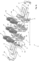
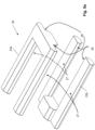
- Filterdrossel (10) zur Verwendung in einem EMI-Filter, wobei die Filterdrossel (10) Folgendes umfasst:- einen geschlossenen Magnetkern (20) mit zwei Kernschenkeln (21, 22), wobei der Magnetkern so konfiguriert ist, dass er aus mindestens zwei Kernsegmenten (23) zusammengesetzt werden kann,- mindestens zwei Spulenträger (30), wobei jeder Spulenträger einen Basisflansch (31) und einen rohrförmigen Abschnitt (32a, 32b) umfasst, der sich in senkrechter Richtung vom Basisflansch erstreckt, wobei der rohrförmige Abschnitt (32a, 32b) eine Öffnung (33) zur Aufnahme eines der beiden Kernschenkel (21, 22) umfasst,- eine Spule (40), die aus einem elektrischen Leiter (41) mit mehreren Windungen gebildet ist, die um den rohrförmigen Abschnitt (32) jedes Spulenträgers (30) angeordnet sind,
wobei die Spulenträger (30) in einem zusammengebauten Zustand der Filterdrossel (10) in einer gestapelten Weise angeordnet sind, so dass ihre Öffnungen (33) koaxial zueinander ausgerichtet sind, wobei sich einer der Kernschenkel (21, 22) durch die Öffnungen (33) erstreckt, und dadurch gekennzeichnet, dass jeder Spulenträger (30) mindestens zwei erste Passelemente (35) umfasst, die an gegenüberliegenden Kanten (34) seines Basisflansches (31) angeordnet sind, wobei die ersten Passelemente (35) des ersten Spulenträgers (30) so konfiguriert sind, dass sie mit den ersten Passelementen (35) des benachbarten zweiten Spulenträgers (30) ineinander greifen, um die beiden Spulenträger (30) lösbar aneinander zu befestigen,- wobei die mindestens zwei ersten Passelemente (35) jeweils ein Teil (38a) und ein korrespondierendes Gegenstück (38b) enthalten, die so konfiguriert sind, dass sie mit dem benachbarten zweiten Spulenträger (30) eine Schnappverbindung (38) bilden, und- wobei sich für jedes erste Passelement (35) das Schnappverbindungsteil (38a) und das Schnappverbindungsgegenstück (38b) in entgegengesetzten axialen Richtungen von der Kante (34) des Basisflansches (31) erstrecken. - Filterdrossel (10) nach Anspruch 1, dadurch gekennzeichnet, dass jeder Spulenträger (30) zusätzlich zu seinem rohrförmigen Abschnitt (32a, 32b) einen weiteren rohrförmigen Abschnitt (32b, 32a) mit einer weiteren ihm zugeordneten Öffnung (33) umfasst, und wobei die Filterdrossel (10) zusätzlich zu der Spule (40) eine weitere Spule (40) umfasst, so dass jeder Spulenträger (30) zwei rohrförmige Abschnitte (32a, 32b) umfasst, die sich in senkrechter Richtung von dem Basisflansch (31) erstrecken, wobei jeder der rohrförmigen Abschnitte (32a, 32b) eine Öffnung (33) zur Aufnahme eines anderen der beiden Kernschenkel (21, 22) enthält, und wobei um jeden rohrförmigen Abschnitt (32a, 32b) des Spulenträgers (30) eine Spule (40) angeordnet ist, die durch einen elektrischen Leiter (41) mit mehreren Windungen gebildet wird.
- Filterdrossel (10) nach Anspruch 1 oder 2, dadurch gekennzeichnet, dass jeder Spulenträger (30) Führungselemente (43a - 43f) enthält, die auf einer Bodenfläche (36a) und/oder einer Deckfläche (36b) seines Basisflansches (31) angeordnet sind, um mindestens einen Anschluss (42a, 42b) der Spule (40) zu positionieren und/oder auszurichten, die durch den elektrischen Leiter (41) gebildet wird.
- Filterdrossel (10) gemäß einem der Ansprüche 1 bis 3, dadurch gekennzeichnet, dass der Basisflansch (31) zwei zweite Passelemente (39a) zum lösbaren Eingriff mit entsprechenden Passelementen (39b) einer Kernklammer (24) umfasst, die so konfiguriert ist, dass sie mindestens eines der mehreren Kernsegmente (23) des Magnetkerns (20) fixiert.
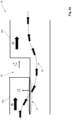
- Filterdrossel (10) gemäß einem der vorstehenden Ansprüche, dadurch gekennzeichnet, dass der Magnetkern (20) einen Bypass-Pfad (25) mit geringer Reluktanz um einen Spalt (26) herum umfasst, wobei der Spalt (26) eine Spaltebenen-Normale (
nGap ) umfasst, wobei die Spaltebenen-Normale parallel zur Ausrichtung der Kernschenkel verläuft, und wobei der Bypass-Pfad (25) ferner einen Überlappungsbereich (27) zwischen zwei Kernsegmenten (23) umfasst, der angrenzend an den Spalt (26) angeordnet ist, und wobei der Überlappungsbereich (27) mit seiner Grenzflächenebenen-Normalen (nOL ) im Wesentlichen senkrecht zur Spaltebenen-Normalen ausgerichtet ist (nGap ) . - Filterdrossel (10) gemäß einem der vorstehenden Ansprüche, dadurch gekennzeichnet, dass der Magnetkern (20) mindestens vier Kernsegmente (23) umfasst, die in mindestens zwei Schichten angeordnet sind, so dass jede Schicht einen geschlossenen magnetischen Teilkern (27a, 27b) mit im Wesentlichen dergleichen Geometrie enthält, der aus mindestens zwei Kernsegmenten (23) gebildet ist, wobei die Teilkerne (27a, 27b) koaxial zueinander ausgerichtet sind.
- Filterdrossel (10) nach Anspruch 6 in Abhängigkeit von Anspruch 5, wobei die Kernsegmente (23) der Teilkerne (27a, 27b) in den verschiedenen Schichten so angeordnet sind, dass die Spalte (26) in den verschiedenen Teilkernen (27a, 27b) versetzt zueinander angeordnet sind.
- Filterdrossel (10) nach einem der vorhergehenden Ansprüche, wobei der elektrische Leiter (41) einen Flachdraht umfasst.
- Filterdrossel (10) nach einem der vorhergehenden Ansprüche, wobei die mehreren Kernsegmente (23) unterschiedliche Kernmaterialien umfassen, so dass ein Material A in einem ersten Kernsegment (23) sich von einem Material B in einem zweiten Kernsegment (23) unterscheidet.
- Filterdrossel (10) gemäß einem der vorhergehenden Ansprüche, wobei die mindestens zwei Spulenträger (30) in Bezug auf ihre Bauart identisch zueinander sind oder abgesehen von unterschiedlichen Längen ihrer rohrförmigen Abschnitte (32a, 32b) identisch zueinander sind.
- Elektrisches Gerät (100), insbesondere ein Wechselrichter, mit einer Filterdrossel (10) nach einem der vorhergehenden Ansprüche, wobei die Filterdrossel (10) in dem elektrischen Gerät (100) als Gleichtaktdrossel betrieben wird.
- Verfahren zur Herstellung einer Filterdrossel (10) nach einem der Ansprüche 1 bis 10, das die folgenden Schritte umfasst:- Bereitstellen der mindestens zwei Kernsegmente (23), die so konfiguriert sind, dass sie zu dem geschlossenen Magnetkern (20) mit zwei Kernschenkeln (21, 22) zusammengebaut werden können,- Bereitstellen des ersten Spulenträgers (30) und des zweiten Spulenträgers (30), wobei jeder Spulenträger (30) den Basisflansch (31) und den rohrförmigen Abschnitt (32) umfasst, der sich in senkrechter Richtung vom Basisflansch (31) erstreckt, und wobei der rohrförmige Abschnitt (32) die Öffnung (33) zum Aufnehmen eines der beiden Kernschenkel (21, 22) umfasst,- Wickeln eines elektrischen Leiters (41) zur Bildung von mindestens zwei Spulen (40) unter Verwendung eines automatischen Wickelverfahrens,- Anordnen der vorgewickelten Spulen (40) auf dem rohrförmigen Abschnitt (32) jeder Spule (30),- Anordnen des ersten Spulenträgers (30) relativ zum zweiten Spulenträger (30) in einer gestapelten Weise übereinander und Verriegeln des ersten Spulenträgers (30) an dem zweiten Spulenträger (30), so dass ihre Öffnungen (33) koaxial zueinander ausgerichtet sind, wobei Anschlüsse (42a, 42b) der Spulen (40) im Wesentlichen in vordefinierten Positionen angeordnet sind,- Einsetzen der Kernsegmente (23) in die Öffnungen (33) der Spulenträger (30), um den geschlossenen Magnetkern (20) zu bilden.
Priority Applications (6)
| Application Number | Priority Date | Filing Date | Title |
|---|---|---|---|
| EP21208886.8A EP4184533B1 (de) | 2021-11-17 | 2021-11-17 | Filterdrossel, deren herstellungsverfahren und elektrische vorrichtung |
| PL21208886.8T PL4184533T3 (pl) | 2021-11-17 | 2021-11-17 | Dławik filtrujący, sposób jego wytwarzania oraz urządzenie elektryczne |
| PCT/EP2022/080359 WO2023088672A1 (en) | 2021-11-17 | 2022-10-31 | Filter-choke, production method thereof and electrical device |
| EP22809163.3A EP4434061A1 (de) | 2021-11-17 | 2022-10-31 | Filterkoks, herstellungsverfahren dafür und elektrische vorrichtung |
| JP2024527153A JP2024542166A (ja) | 2021-11-17 | 2022-10-31 | フィルタチョーク、フィルタチョークの製造方法、および電気機器 |
| US18/665,988 US20240304381A1 (en) | 2021-11-17 | 2024-05-16 | Filter-choke, production method thereof and electrical device |
Applications Claiming Priority (1)
| Application Number | Priority Date | Filing Date | Title |
|---|---|---|---|
| EP21208886.8A EP4184533B1 (de) | 2021-11-17 | 2021-11-17 | Filterdrossel, deren herstellungsverfahren und elektrische vorrichtung |
Publications (3)
| Publication Number | Publication Date |
|---|---|
| EP4184533A1 EP4184533A1 (de) | 2023-05-24 |
| EP4184533B1 true EP4184533B1 (de) | 2025-07-02 |
| EP4184533C0 EP4184533C0 (de) | 2025-07-02 |
Family
ID=78695521
Family Applications (1)
| Application Number | Title | Priority Date | Filing Date |
|---|---|---|---|
| EP21208886.8A Active EP4184533B1 (de) | 2021-11-17 | 2021-11-17 | Filterdrossel, deren herstellungsverfahren und elektrische vorrichtung |
Country Status (2)
| Country | Link |
|---|---|
| EP (1) | EP4184533B1 (de) |
| PL (1) | PL4184533T3 (de) |
Families Citing this family (2)
| Publication number | Priority date | Publication date | Assignee | Title |
|---|---|---|---|---|
| CN117038281A (zh) * | 2023-09-18 | 2023-11-10 | 惠州市可立克电子有限公司 | 三相差模电感磁集成结构 |
| EP4542588A1 (de) * | 2023-10-19 | 2025-04-23 | Delta Electronics (Thailand) Public Co., Ltd. | Magnetische komponente |
Family Cites Families (8)
| Publication number | Priority date | Publication date | Assignee | Title |
|---|---|---|---|---|
| JPS55110010A (en) * | 1979-02-19 | 1980-08-25 | Matsushita Electric Ind Co Ltd | Current transformer |
| US5155676A (en) * | 1991-11-01 | 1992-10-13 | International Business Machines Corporation | Gapped/ungapped magnetic core |
| JP2566052Y2 (ja) * | 1992-01-27 | 1998-03-25 | 株式会社トーキン | トランス |
| WO2013065183A1 (ja) * | 2011-11-04 | 2013-05-10 | トヨタ自動車株式会社 | リアクトルおよびその製造方法 |
| JP2014150220A (ja) * | 2013-02-04 | 2014-08-21 | Toyota Motor Corp | リアクトル |
| CN203858954U (zh) | 2014-04-30 | 2014-10-01 | 台达电子(东莞)有限公司 | 扼流器 |
| JP6519741B2 (ja) * | 2015-07-15 | 2019-05-29 | 株式会社オートネットワーク技術研究所 | リアクトル、コンバータ、および電力変換装置 |
| JP6458720B2 (ja) * | 2015-12-04 | 2019-01-30 | トヨタ自動車株式会社 | リアクトル |
-
2021
- 2021-11-17 EP EP21208886.8A patent/EP4184533B1/de active Active
- 2021-11-17 PL PL21208886.8T patent/PL4184533T3/pl unknown
Also Published As
| Publication number | Publication date |
|---|---|
| EP4184533A1 (de) | 2023-05-24 |
| PL4184533T3 (pl) | 2025-11-12 |
| EP4184533C0 (de) | 2025-07-02 |
Similar Documents
| Publication | Publication Date | Title |
|---|---|---|
| EP3288049B1 (de) | Oberflächenmontierbare drosselspule und verfahren zu ihrer herstellung | |
| CN102428527B (zh) | 表面安装磁性部件及其制造方法 | |
| US8310332B2 (en) | High current amorphous powder core inductor | |
| EP4184533B1 (de) | Filterdrossel, deren herstellungsverfahren und elektrische vorrichtung | |
| KR102834772B1 (ko) | 변압기 인덕터 조합 장치 | |
| EP2455951B1 (de) | Induktionsvorrichtung | |
| US20150070121A1 (en) | Coil component and method of manufacturing the same | |
| US8791786B2 (en) | Coil device | |
| CA2770152A1 (en) | High current magnetic component and methods of manufacture | |
| JP4654680B2 (ja) | 電動機 | |
| US9905356B2 (en) | Magnetic component for a switching power supply and a method of manufacturing a magnetic component | |
| US20240304381A1 (en) | Filter-choke, production method thereof and electrical device | |
| CN103915246B (zh) | 线圈部件 | |
| KR102399391B1 (ko) | 플랫타입 트랜스포머 | |
| US7414509B2 (en) | Miniature surface-mount electronic component and method for manufacturing the same | |
| CN118251737A (zh) | 滤波器-扼流圈、其生产方法以及电气设备 | |
| CN110476216B (zh) | 线圈部件 | |
| JPH051049Y2 (de) | ||
| JP2001313220A (ja) | インダクタンス部品 | |
| CN216751530U (zh) | 电磁兼容滤波器 | |
| KR102698084B1 (ko) | 변압기용 나노코어 어셈블리 | |
| US12112874B2 (en) | Inductor | |
| JPH0655229U (ja) | インダクタ及びこれに使用されるコアホルダー | |
| CN116313434A (zh) | 线圈装置 |
Legal Events
| Date | Code | Title | Description |
|---|---|---|---|
| PUAI | Public reference made under article 153(3) epc to a published international application that has entered the european phase |
Free format text: ORIGINAL CODE: 0009012 |
|
| STAA | Information on the status of an ep patent application or granted ep patent |
Free format text: STATUS: THE APPLICATION HAS BEEN PUBLISHED |
|
| AK | Designated contracting states |
Kind code of ref document: A1 Designated state(s): AL AT BE BG CH CY CZ DE DK EE ES FI FR GB GR HR HU IE IS IT LI LT LU LV MC MK MT NL NO PL PT RO RS SE SI SK SM TR |
|
| STAA | Information on the status of an ep patent application or granted ep patent |
Free format text: STATUS: REQUEST FOR EXAMINATION WAS MADE |
|
| 17P | Request for examination filed |
Effective date: 20231106 |
|
| RBV | Designated contracting states (corrected) |
Designated state(s): AL AT BE BG CH CY CZ DE DK EE ES FI FR GB GR HR HU IE IS IT LI LT LU LV MC MK MT NL NO PL PT RO RS SE SI SK SM TR |
|
| GRAP | Despatch of communication of intention to grant a patent |
Free format text: ORIGINAL CODE: EPIDOSNIGR1 |
|
| STAA | Information on the status of an ep patent application or granted ep patent |
Free format text: STATUS: GRANT OF PATENT IS INTENDED |
|
| RIC1 | Information provided on ipc code assigned before grant |
Ipc: H01F 27/26 20060101ALN20250131BHEP Ipc: H01F 3/10 20060101ALN20250131BHEP Ipc: H01F 27/30 20060101ALI20250131BHEP Ipc: H01F 5/02 20060101ALI20250131BHEP Ipc: H01F 37/00 20060101ALI20250131BHEP Ipc: H01F 3/12 20060101ALI20250131BHEP Ipc: H01F 27/32 20060101ALI20250131BHEP Ipc: H01F 5/04 20060101AFI20250131BHEP |
|
| INTG | Intention to grant announced |
Effective date: 20250218 |
|
| GRAS | Grant fee paid |
Free format text: ORIGINAL CODE: EPIDOSNIGR3 |
|
| GRAA | (expected) grant |
Free format text: ORIGINAL CODE: 0009210 |
|
| STAA | Information on the status of an ep patent application or granted ep patent |
Free format text: STATUS: THE PATENT HAS BEEN GRANTED |
|
| AK | Designated contracting states |
Kind code of ref document: B1 Designated state(s): AL AT BE BG CH CY CZ DE DK EE ES FI FR GB GR HR HU IE IS IT LI LT LU LV MC MK MT NL NO PL PT RO RS SE SI SK SM TR |
|
| REG | Reference to a national code |
Ref country code: GB Ref legal event code: FG4D |
|
| REG | Reference to a national code |
Ref country code: CH Ref legal event code: EP |
|
| REG | Reference to a national code |
Ref country code: DE Ref legal event code: R096 Ref document number: 602021033248 Country of ref document: DE |
|
| REG | Reference to a national code |
Ref country code: IE Ref legal event code: FG4D |
|
| U01 | Request for unitary effect filed |
Effective date: 20250708 |
|
| U07 | Unitary effect registered |
Designated state(s): AT BE BG DE DK EE FI FR IT LT LU LV MT NL PT RO SE SI Effective date: 20250711 |
|
| U20 | Renewal fee for the european patent with unitary effect paid |
Year of fee payment: 5 Effective date: 20251117 |
|
| PG25 | Lapsed in a contracting state [announced via postgrant information from national office to epo] |
Ref country code: IS Free format text: LAPSE BECAUSE OF FAILURE TO SUBMIT A TRANSLATION OF THE DESCRIPTION OR TO PAY THE FEE WITHIN THE PRESCRIBED TIME-LIMIT Effective date: 20251102 |
|
| PGFP | Annual fee paid to national office [announced via postgrant information from national office to epo] |
Ref country code: GB Payment date: 20251120 Year of fee payment: 5 |
|
| PG25 | Lapsed in a contracting state [announced via postgrant information from national office to epo] |
Ref country code: NO Free format text: LAPSE BECAUSE OF FAILURE TO SUBMIT A TRANSLATION OF THE DESCRIPTION OR TO PAY THE FEE WITHIN THE PRESCRIBED TIME-LIMIT Effective date: 20251002 |
|
| PG25 | Lapsed in a contracting state [announced via postgrant information from national office to epo] |
Ref country code: HR Free format text: LAPSE BECAUSE OF FAILURE TO SUBMIT A TRANSLATION OF THE DESCRIPTION OR TO PAY THE FEE WITHIN THE PRESCRIBED TIME-LIMIT Effective date: 20250702 |
|
| PG25 | Lapsed in a contracting state [announced via postgrant information from national office to epo] |
Ref country code: GR Free format text: LAPSE BECAUSE OF FAILURE TO SUBMIT A TRANSLATION OF THE DESCRIPTION OR TO PAY THE FEE WITHIN THE PRESCRIBED TIME-LIMIT Effective date: 20251003 |
|
| PG25 | Lapsed in a contracting state [announced via postgrant information from national office to epo] |
Ref country code: CZ Free format text: LAPSE BECAUSE OF FAILURE TO SUBMIT A TRANSLATION OF THE DESCRIPTION OR TO PAY THE FEE WITHIN THE PRESCRIBED TIME-LIMIT Effective date: 20250702 |
|
| PGFP | Annual fee paid to national office [announced via postgrant information from national office to epo] |
Ref country code: PL Payment date: 20251106 Year of fee payment: 5 |
|
| PG25 | Lapsed in a contracting state [announced via postgrant information from national office to epo] |
Ref country code: RS Free format text: LAPSE BECAUSE OF FAILURE TO SUBMIT A TRANSLATION OF THE DESCRIPTION OR TO PAY THE FEE WITHIN THE PRESCRIBED TIME-LIMIT Effective date: 20251002 |
|
| PG25 | Lapsed in a contracting state [announced via postgrant information from national office to epo] |
Ref country code: ES Free format text: LAPSE BECAUSE OF FAILURE TO SUBMIT A TRANSLATION OF THE DESCRIPTION OR TO PAY THE FEE WITHIN THE PRESCRIBED TIME-LIMIT Effective date: 20250702 |