EP4184418A1 - Bestimmungsvorrichtung, bestimmungsverfahren und programm - Google Patents
Bestimmungsvorrichtung, bestimmungsverfahren und programm Download PDFInfo
- Publication number
- EP4184418A1 EP4184418A1 EP21842582.5A EP21842582A EP4184418A1 EP 4184418 A1 EP4184418 A1 EP 4184418A1 EP 21842582 A EP21842582 A EP 21842582A EP 4184418 A1 EP4184418 A1 EP 4184418A1
- Authority
- EP
- European Patent Office
- Prior art keywords
- information
- area
- stay
- time
- persons
- Prior art date
- Legal status (The legal status is an assumption and is not a legal conclusion. Google has not performed a legal analysis and makes no representation as to the accuracy of the status listed.)
- Pending
Links
Images


Classifications
-
- G—PHYSICS
- G06—COMPUTING OR CALCULATING; COUNTING
- G06Q—INFORMATION AND COMMUNICATION TECHNOLOGY [ICT] SPECIALLY ADAPTED FOR ADMINISTRATIVE, COMMERCIAL, FINANCIAL, MANAGERIAL OR SUPERVISORY PURPOSES; SYSTEMS OR METHODS SPECIALLY ADAPTED FOR ADMINISTRATIVE, COMMERCIAL, FINANCIAL, MANAGERIAL OR SUPERVISORY PURPOSES, NOT OTHERWISE PROVIDED FOR
- G06Q50/00—Information and communication technology [ICT] specially adapted for implementation of business processes of specific business sectors, e.g. utilities or tourism
- G06Q50/04—Manufacturing
-
- G—PHYSICS
- G06—COMPUTING OR CALCULATING; COUNTING
- G06V—IMAGE OR VIDEO RECOGNITION OR UNDERSTANDING
- G06V20/00—Scenes; Scene-specific elements
- G06V20/50—Context or environment of the image
- G06V20/52—Surveillance or monitoring of activities, e.g. for recognising suspicious objects
- G06V20/53—Recognition of crowd images, e.g. recognition of crowd congestion
-
- G—PHYSICS
- G06—COMPUTING OR CALCULATING; COUNTING
- G06F—ELECTRIC DIGITAL DATA PROCESSING
- G06F16/00—Information retrieval; Database structures therefor; File system structures therefor
- G06F16/90—Details of database functions independent of the retrieved data types
- G06F16/904—Browsing; Visualisation therefor
-
- G—PHYSICS
- G06—COMPUTING OR CALCULATING; COUNTING
- G06F—ELECTRIC DIGITAL DATA PROCESSING
- G06F16/00—Information retrieval; Database structures therefor; File system structures therefor
- G06F16/90—Details of database functions independent of the retrieved data types
- G06F16/907—Retrieval characterised by using metadata, e.g. metadata not derived from the content or metadata generated manually
- G06F16/909—Retrieval characterised by using metadata, e.g. metadata not derived from the content or metadata generated manually using geographical or spatial information, e.g. location
-
- G—PHYSICS
- G06—COMPUTING OR CALCULATING; COUNTING
- G06Q—INFORMATION AND COMMUNICATION TECHNOLOGY [ICT] SPECIALLY ADAPTED FOR ADMINISTRATIVE, COMMERCIAL, FINANCIAL, MANAGERIAL OR SUPERVISORY PURPOSES; SYSTEMS OR METHODS SPECIALLY ADAPTED FOR ADMINISTRATIVE, COMMERCIAL, FINANCIAL, MANAGERIAL OR SUPERVISORY PURPOSES, NOT OTHERWISE PROVIDED FOR
- G06Q10/00—Administration; Management
- G06Q10/06—Resources, workflows, human or project management; Enterprise or organisation planning; Enterprise or organisation modelling
- G06Q10/063—Operations research, analysis or management
- G06Q10/0631—Resource planning, allocation, distributing or scheduling for enterprises or organisations
- G06Q10/06311—Scheduling, planning or task assignment for a person or group
- G06Q10/063114—Status monitoring or status determination for a person or group
-
- G—PHYSICS
- G06—COMPUTING OR CALCULATING; COUNTING
- G06Q—INFORMATION AND COMMUNICATION TECHNOLOGY [ICT] SPECIALLY ADAPTED FOR ADMINISTRATIVE, COMMERCIAL, FINANCIAL, MANAGERIAL OR SUPERVISORY PURPOSES; SYSTEMS OR METHODS SPECIALLY ADAPTED FOR ADMINISTRATIVE, COMMERCIAL, FINANCIAL, MANAGERIAL OR SUPERVISORY PURPOSES, NOT OTHERWISE PROVIDED FOR
- G06Q50/00—Information and communication technology [ICT] specially adapted for implementation of business processes of specific business sectors, e.g. utilities or tourism
- G06Q50/10—Services
-
- G—PHYSICS
- G08—SIGNALLING
- G08B—SIGNALLING OR CALLING SYSTEMS; ORDER TELEGRAPHS; ALARM SYSTEMS
- G08B21/00—Alarms responsive to a single specified undesired or abnormal condition and not otherwise provided for
- G08B21/18—Status alarms
-
- G—PHYSICS
- G08—SIGNALLING
- G08B—SIGNALLING OR CALLING SYSTEMS; ORDER TELEGRAPHS; ALARM SYSTEMS
- G08B25/00—Alarm systems in which the location of the alarm condition is signalled to a central station, e.g. fire or police telegraphic systems
- G08B25/14—Central alarm receiver or annunciator arrangements
-
- G—PHYSICS
- G08—SIGNALLING
- G08B—SIGNALLING OR CALLING SYSTEMS; ORDER TELEGRAPHS; ALARM SYSTEMS
- G08B5/00—Visible signalling systems, e.g. personal calling systems, remote indication of seats occupied
- G08B5/22—Visible signalling systems, e.g. personal calling systems, remote indication of seats occupied using electric transmission; using electromagnetic transmission
-
- G—PHYSICS
- G16—INFORMATION AND COMMUNICATION TECHNOLOGY [ICT] SPECIALLY ADAPTED FOR SPECIFIC APPLICATION FIELDS
- G16H—HEALTHCARE INFORMATICS, i.e. INFORMATION AND COMMUNICATION TECHNOLOGY [ICT] SPECIALLY ADAPTED FOR THE HANDLING OR PROCESSING OF MEDICAL OR HEALTHCARE DATA
- G16H40/00—ICT specially adapted for the management or administration of healthcare resources or facilities; ICT specially adapted for the management or operation of medical equipment or devices
- G16H40/20—ICT specially adapted for the management or administration of healthcare resources or facilities; ICT specially adapted for the management or operation of medical equipment or devices for the management or administration of healthcare resources or facilities, e.g. managing hospital staff or surgery rooms
-
- G—PHYSICS
- G16—INFORMATION AND COMMUNICATION TECHNOLOGY [ICT] SPECIALLY ADAPTED FOR SPECIFIC APPLICATION FIELDS
- G16H—HEALTHCARE INFORMATICS, i.e. INFORMATION AND COMMUNICATION TECHNOLOGY [ICT] SPECIALLY ADAPTED FOR THE HANDLING OR PROCESSING OF MEDICAL OR HEALTHCARE DATA
- G16H40/00—ICT specially adapted for the management or administration of healthcare resources or facilities; ICT specially adapted for the management or operation of medical equipment or devices
- G16H40/60—ICT specially adapted for the management or administration of healthcare resources or facilities; ICT specially adapted for the management or operation of medical equipment or devices for the operation of medical equipment or devices
- G16H40/63—ICT specially adapted for the management or administration of healthcare resources or facilities; ICT specially adapted for the management or operation of medical equipment or devices for the operation of medical equipment or devices for local operation
-
- G—PHYSICS
- G16—INFORMATION AND COMMUNICATION TECHNOLOGY [ICT] SPECIALLY ADAPTED FOR SPECIFIC APPLICATION FIELDS
- G16H—HEALTHCARE INFORMATICS, i.e. INFORMATION AND COMMUNICATION TECHNOLOGY [ICT] SPECIALLY ADAPTED FOR THE HANDLING OR PROCESSING OF MEDICAL OR HEALTHCARE DATA
- G16H40/00—ICT specially adapted for the management or administration of healthcare resources or facilities; ICT specially adapted for the management or operation of medical equipment or devices
- G16H40/60—ICT specially adapted for the management or administration of healthcare resources or facilities; ICT specially adapted for the management or operation of medical equipment or devices for the operation of medical equipment or devices
- G16H40/67—ICT specially adapted for the management or administration of healthcare resources or facilities; ICT specially adapted for the management or operation of medical equipment or devices for the operation of medical equipment or devices for remote operation
-
- G—PHYSICS
- G16—INFORMATION AND COMMUNICATION TECHNOLOGY [ICT] SPECIALLY ADAPTED FOR SPECIFIC APPLICATION FIELDS
- G16H—HEALTHCARE INFORMATICS, i.e. INFORMATION AND COMMUNICATION TECHNOLOGY [ICT] SPECIALLY ADAPTED FOR THE HANDLING OR PROCESSING OF MEDICAL OR HEALTHCARE DATA
- G16H50/00—ICT specially adapted for medical diagnosis, medical simulation or medical data mining; ICT specially adapted for detecting, monitoring or modelling epidemics or pandemics
- G16H50/30—ICT specially adapted for medical diagnosis, medical simulation or medical data mining; ICT specially adapted for detecting, monitoring or modelling epidemics or pandemics for calculating health indices; for individual health risk assessment
-
- G—PHYSICS
- G16—INFORMATION AND COMMUNICATION TECHNOLOGY [ICT] SPECIALLY ADAPTED FOR SPECIFIC APPLICATION FIELDS
- G16H—HEALTHCARE INFORMATICS, i.e. INFORMATION AND COMMUNICATION TECHNOLOGY [ICT] SPECIALLY ADAPTED FOR THE HANDLING OR PROCESSING OF MEDICAL OR HEALTHCARE DATA
- G16H50/00—ICT specially adapted for medical diagnosis, medical simulation or medical data mining; ICT specially adapted for detecting, monitoring or modelling epidemics or pandemics
- G16H50/80—ICT specially adapted for medical diagnosis, medical simulation or medical data mining; ICT specially adapted for detecting, monitoring or modelling epidemics or pandemics for detecting, monitoring or modelling epidemics or pandemics, e.g. flu
-
- H—ELECTRICITY
- H04—ELECTRIC COMMUNICATION TECHNIQUE
- H04W—WIRELESS COMMUNICATION NETWORKS
- H04W4/00—Services specially adapted for wireless communication networks; Facilities therefor
- H04W4/02—Services making use of location information
- H04W4/021—Services related to particular areas, e.g. point of interest [POI] services, venue services or geofences
-
- H—ELECTRICITY
- H04—ELECTRIC COMMUNICATION TECHNIQUE
- H04W—WIRELESS COMMUNICATION NETWORKS
- H04W4/00—Services specially adapted for wireless communication networks; Facilities therefor
- H04W4/02—Services making use of location information
- H04W4/029—Location-based management or tracking services
-
- H—ELECTRICITY
- H04—ELECTRIC COMMUNICATION TECHNIQUE
- H04W—WIRELESS COMMUNICATION NETWORKS
- H04W4/00—Services specially adapted for wireless communication networks; Facilities therefor
- H04W4/30—Services specially adapted for particular environments, situations or purposes
- H04W4/33—Services specially adapted for particular environments, situations or purposes for indoor environments, e.g. buildings
-
- Y—GENERAL TAGGING OF NEW TECHNOLOGICAL DEVELOPMENTS; GENERAL TAGGING OF CROSS-SECTIONAL TECHNOLOGIES SPANNING OVER SEVERAL SECTIONS OF THE IPC; TECHNICAL SUBJECTS COVERED BY FORMER USPC CROSS-REFERENCE ART COLLECTIONS [XRACs] AND DIGESTS
- Y02—TECHNOLOGIES OR APPLICATIONS FOR MITIGATION OR ADAPTATION AGAINST CLIMATE CHANGE
- Y02P—CLIMATE CHANGE MITIGATION TECHNOLOGIES IN THE PRODUCTION OR PROCESSING OF GOODS
- Y02P90/00—Enabling technologies with a potential contribution to greenhouse gas [GHG] emissions mitigation
- Y02P90/30—Computing systems specially adapted for manufacturing
Definitions
- Embodiments described herein relate generally to a determination apparatus, a determination method, and a program for determining congestion of persons, e.g., workers, in areas within a monitoring target region, e.g., a factory.
- Layout optimization and traffic flow line optimization are essential for facilities having a limited premises area, such as a factory, to realize high production efficiency.
- Objects intended herein include providing a determination apparatus, a determination method, and a program for determining congestion of persons such as workers in each area within a monitoring target region such as a factory.
- a determination apparatus for determining congestion of persons in each area in a monitoring target region includes:
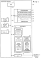
- FIG. 1 is a block diagram showing an exemplary electronic circuitry configuration of a determination apparatus to which a determination method according to an embodiment is applied.
- This determination apparatus 10 is an apparatus to determine congestion, proximity, etc. of persons in a monitoring target region.
- the electronic circuitry of the determination apparatus 10 includes a CPU 12, a recording medium reader unit 14, a communication unit 15, a display unit 16 (e.g., a display), a memory 20, and a storage device 30, which are connected to one another via a bus 11.
- the memory 20 stores a processing module 21, a stay information acquisition module 22, a congestion determination module 23, a proximity determination module 24, and a display control module 25, in the form of a program or programs for realizing the determination apparatus 10.
- program modules 21 to 25 may be stored in advance in the memory 20 or may be read from an external recording medium 13, which may be a memory card or the like, via the recording medium reader unit 14, and stored in the memory 20.
- the program modules 21 to 25 are adapted to be non-rewritable.
- the memory 20 secures a writable data area 29 as a memory area for storing rewritable data.
- the CPU 12 is one example of a processor or processors available for executing each of the program modules 21 to 25, and it controls operations of each circuitry component according to each of the program modules 21 to 25.
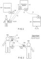
- FIG. 2 is a conceptual diagram showing one example of connection relationships of the determination apparatus to other devices.
- a position sensor 110 with a unique sensor ID is attached to each worker 100.
- the position sensor 110 measures the position of the worker 100 by means of a GPS function, a WiFi function, or a beacon 125 and sends the position information based on the measurement together with the sensor ID to the determination apparatus 10 via a communication network 70.
- an image sensor 115 which may be a camera or the like, may be attached to each worker 100.
- the image sensor 115 is likewise assigned a unique sensor ID.
- the image sensor 115 acquires an image along the line of sight of each worker 100 and sends the acquired image information together with the sensor ID to the determination apparatus 10 via the communication network 70.
- the storage device 30 includes a worker database 31, a position information database 32, and a congestion/proximity determination information database.
- the worker database 31 stores a worker ID (for example, an employee number or the like) of each worker 100. Also, the worker database 31 stores the sensor IDs of the position sensor 110 and the image sensor 115 attached to each worker 100, in association with the worker ID of the corresponding worker 100.
- a worker ID for example, an employee number or the like
- the position information database 32 is a database for storing position information on each worker 100 in the factory together with time information, in association with the worker ID of the worker 100.
- the congestion/proximity determination information database is a database for storing information related to results of determinations by the congestion determination module 23 and the proximity determination module 24.
- the storage device 30 storing these databases 31 to 33 is constituted by, for example, a solid state drive (SSD), a hard disk drive (HDD), etc.
- SSD solid state drive
- HDD hard disk drive
- the communication unit 15 is connected to the communication network 70 so that it receives position information sent from the position sensor 110 and image information sent from the image sensor 115 together with their sensor IDs via the communication network 70 and so that it outputs the received position information or image information to the processing module 21 together with the sensor ID.
- FIG. 2 shows, as one example, a case where the position information (and/or the image information) from the position sensor 110 (and/or the image sensor 115) is received via the communication network 70 by the communication unit 15 implemented by a gateway.
- the communication unit 15 may output data necessary for displaying the monitoring result, etc. to the external terminal 130 via the communication network 70 as shown in FIG. 2 .
- the processing module 21 in response to the position information and the sensor ID being output from the communication unit 15, acquires the worker ID associated with this sensor ID from the worker database 31 and outputs the worker ID together with the position information and the sensor ID to the position information database 32.
- the processing module 21 in response to the image information and the sensor ID being output from the communication unit 15, acquires the worker ID associated with this sensor ID from the worker database 31 and additionally extracts position information from the image information using, for example, AI. The processing module 21 then similarly outputs the worker ID together with the extracted position information and the sensor ID to the position information database 32.
- the position information database 32 stores the position information output from the processing module 21 in association with time information, the worker ID, and one or more sensor IDs.
- the position information may be expressed in the form of coordinates which are obtainable through, for example, the three-point positioning technique using a Bluetooth (registered trademark) beacon, etc.
- the position information database 32 may use time information measured by an internal clock (not illustrated) of the determination apparatus 10 or time information synchronized with a clock (time measurement means) of an external system connected to the determination apparatus 10.
- the stay information acquisition module 22 acquires, for each area in the factory, information on one or more workers 100 who have made a stay there and also acquires, for each worker 100 who has made a stay, information on a time slot during which the stay was made, from the position information database 32 based on the position information and the time information stored in association with the worker IDs.
- the congestion determination module 23 determines, based on the result acquired by the stay information acquisition module 22, an area in which multiple people have stayed for a predetermined continuous length of time (for example, 15 minutes) or more as an area of high congestion (which may be called a "congested area” below).
- the proximity determination module 24 determines, for each area, multiple workers 100 who are staying close to one another within a predetermined proximity distance (for example, 1 m) or shorter, and a time slot during which each of such workers 100 continuously stays within this proximity distance or shorter, based on the position information and the time information stored in the position information database 32 in association with the worker IDs.
- a predetermined proximity distance for example, 1 m
- the proximity determination module 24 determines, for each area, multiple workers 100 who are staying close to one another within a predetermined proximity distance (for example, 1 m) or shorter, and a time slot during which each of such workers 100 continuously stays within this proximity distance or shorter, based on the position information and the time information stored in the position information database 32 in association with the worker IDs.
- the proximity determination module 24 further determines that the workers 100 are in a state of proximity to each other, if a time length corresponding to the determined time slot is equal to or greater than a predetermined continuous time length (for example, 15 minutes) .
- the proximity determination module 24 calculates, for the multiple workers 100 concurrently staying in one area, a proximity distance from one another in a given time based on the position information and the time information stored in the position information database 32.
- the proximity distance between two workers may be calculated using, for example, a trigonometric function.
- FIG. 3 is an example for illustrating a method of calculating a proximity distance between two workers using a trigonometric function.
- a worker 100A and a worker 100C each wear a position sensor 110 of a wristwatch type.
- the position information database 32 stores position information (x 1 , y 1 ) for position A of the worker 100A at a given timing and position information (x 2 , y 2 ) for position C of the worker 100C.
- the proximity determination module 24 calculates the distance between the position A of the worker 100A and the position C of the worker 100C according to the following formula. x 2 ⁇ x 1 2 + y 2 ⁇ y 1 2 1 / 2
- this formula assumes the workers 100A and 100C to be comparable in height, and handles them in two dimensions of x and y coordinates. However, they may be handled in three dimensions by extending the two dimensions to three dimensions of x, y, and z coordinates and conducting a similar mathematical procedure. Note also that, since the distance between the position A and the position C is small, calibration that takes into account the arc of the earth is not required.
- the proximity determination module 24 is able to calculate the distance between workers in a given time. Therefore, the proximity determination module 24 can determine workers 100 (e.g., the worker 100A and the worker 100C) who have been continuously close to each other for, for example, 15 minutes or longer, that is, the workers 100 who satisfy the proximity condition.
- workers 100 e.g., the worker 100A and the worker 100C
- the proximity determination module 24 stores, for each area, and in the congestion/proximity determination information database, the worker IDs of the respective workers 100 (e.g., the worker 100A and the worker 100C) determined to be satisfying the proximity condition, in association with the time information and the position information corresponding to the time slot and the positions determined for these workers 100 (e.g., the worker 100A and the worker 100C) and representing the continuous stay within the proximity distance or shorter.
- the worker IDs of the respective workers 100 e.g., the worker 100A and the worker 100C
- the proximity determination module 24 stores, for each area, and in the congestion/proximity determination information database, the worker IDs of the respective workers 100 (e.g., the worker 100A and the worker 100C) determined to be satisfying the proximity condition, in association with the time information and the position information corresponding to the time slot and the positions determined for these workers 100 (e.g., the worker 100A and the worker 100C) and representing the continuous stay within the proximity distance or shorter.
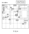
- the display control module 25 based on the information stored in the congestion/proximity determination information database 33, causes the display unit 16, or the external terminal 130 via the communication network 70, to display through a display screen a factory map showing each area with a clear indication of the total value of the lengths of time for which the workers 100 determined to be satisfying the proximity condition have continuously stayed within the proximity distance or shorter.
- FIGS. 4 and 5 each show an example of this.
- FIG. 4 is a plan view showing an internal layout of the factory, which is one example of what is displayed on the screen with the total value of proximity time for each area.
- FIG. 4 applies hatching to each of the areas of which the total value of proximity time is equal to or greater than 0.
- the total value is displayed based on the number in units of "minutes".
- the areas may be divided into two groups according to their total values, and in such instances, areas shown with two-direction hatching are areas belonging to a group with large total values, and areas shown with single-direction hatching are areas belonging to a group with small total values.
- the circled item "15" is an area ID for identifying the area.
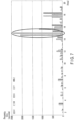
- FIG. 5 is a diagram showing another example of what is displayed on the screen with the total value of proximity time for each area.
- the horizontal axis indicates areas and the vertical axis indicates proximity time (minutes).
- the area "15" has a proximity time of 42 (minutes) in total, and it is understandable that the proximity time is continuous for 15 minutes or longer.
- the display control module 25 may also cause the display unit 16, or the external terminal 130 via the communication network 70, to display through the display screen an object as illustrated by FIG. 5 but with a worker-by-worker breakdown of the proximity time shown.
- FIGS. 6 and 7 each show an example of this.
- FIG. 6 is a diagram showing an example of what is displayed on the screen with a worker-by-worker breakdown of the total value of proximity time for each area.
- FIG. 7 is a diagram showing another example of what is displayed on the screen with a worker-by-worker breakdown of the total value of proximity time for each area.
- the horizontal axis indicates areas and the vertical axis indicates proximity time (minutes).
- the display control module 25 may further cause the display unit 16, or the external terminal 130 via the communication network 70, to display through the display screen an object as illustrated by FIGS. 6 and 7 but with a breakdown of the total value of proximity time given for each time slot.
- FIG. 8 shows an example of this.
- FIG. 8 is a table showing one example of what is displayed on the screen with, for each worker and for each time slot, the breakdown of the total value of proximity time shown in FIGS. 6 and 7 .
- the vertical axis indicates areas.
- the horizontal axis indicates, along the first row, time slots and, along the second row, workers.
- the numerical values shown in FIG. 8 are proximity time values of the respective workers, which are given in units of minutes and displayed one by one for each area and each time slot.
- FIG. 8 employs a table format as a mere example of the display format in which the breakdown of the total value of proximity time shown in FIGS. 6 and 7 is presented for each worker and each time slot.
- Other display formats including a graph format may also be employed.
- the display control module 25 may further cause the display unit 16, or the external terminal 130 via the communication network 70, to display through the display screen a clear indication of, for each area, each of the workers 100 determined to have stayed there in a state of proximity to one another within the proximity distance or shorter, together with the proximity time.
- FIG. 9 shows an example of this.
- FIG. 9 is a table showing an example of what is displayed on the screen with, for each area, a clear indication of each worker 100 determined to have stayed there in a proximity state and its proximity time.
- the vertical axis indicates proximity time (minutes).
- the horizontal axis indicates, along the first row, areas and, along the second row, workers.
- the numerical value "1" shown in FIG. 9 indicates the worker 100 who stayed in the area indicated by the horizontal axis, for the time indicated by the vertical axis.
- FIG. 9 employs a table format as a mere example of the display format in which the workers 100 determined to have stayed in an area in a state of proximity to one another within the proximity distance or shorter, that is, the workers 100 determined to be in a proximity state, are clearly indicated together with the proximity time for each area.
- Other display formats including a graph format may also be employed.
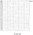
- the display control module 25 may cause the display unit 16, or the external terminal 130 via the communication network 70, to display through the display screen a simplified object as shown in FIG. 10 , which is obtained from an object as shown in FIG. 9 .
- FIG. 10 shows an example of this.
- FIG. 10 is a table showing an example of what is displayed on the screen with a clear indication of each worker 100 determined to be in a proximity state and the proximity time lengths.
- the vertical axis indicates proximity time (minutes) and the horizontal axis indicates workers.
- FIG. 9 The numerical value "1" shown in FIG. 9 indicates a worker 100 who stayed for the proximity time indicated by the vertical axis.
- FIG. 10 is a version where the areas indicated along the first row of the horizontal axis in FIG. 9 are ignored and the display object is limited to only the workers.
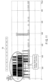
- FIG. 11 shows an example of this.
- FIG. 11 is a diagram showing one example of what is displayed on the screen with a clear indication of a history of changes in the number of persons determined to be in a proximity state in a given area.
- the horizontal axis indicates time and the vertical axis indicates the number of persons who have made a stay.
- solid lines represent changes in the number of persons determined to be in a proximity state.
- time slots that involve many solid lines appear dark, which indicates that partners in the proximity relationship have frequently changed.
- a larger height in the vertical direction means an increased number of partners in the proximity relationship. Therefore, it can be recognized that, if a large height in the vertical direction is displayed, many workers are in a state of proximity, and if the size of the dark part is large, the workers frequently move in and move out. That is, the time slots and the degrees of proximity occurrence can be presented visually.
- FIG. 11 also shows display of an area selection button EA. Users may designate a desired area through the area selection button EA so that the display object is switched to the history of changes for the designated area.
- the congestion/proximity determination information database stores, for each area, the worker IDs of the respective workers 100 determined to be satisfying the proximity condition, and also the time information and the position information corresponding to the time slots and the positions determined for these workers 100 and representing the stay in each area in a proximate state.
- this enables the display control module 25 to cause the display actions on the screen as illustrated in FIGS. 4 to 11 , based on the information stored in the congestion/proximity determination information database.
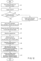
- FIG. 12 is a flowchart showing an exemplary operation of the determination apparatus to which the determination method according to the embodiment is applied.
- a position sensor 110 with a unique sensor ID is attached to each worker 100.
- the image sensor 115 which may be a camera or the like, may be attached to each worker 100.
- the position information on each worker 100 measured by the position sensor 110 i.e., sensing information obtained by the position sensor 110
- the image information acquired by the image sensor 115 i.e., sensing information obtained by the image sensor 115, is also sent from the image sensor 115 to the determination apparatus 10 via the communication network 70, together with the corresponding sensor ID (S1).
- the position information, i.e., sensing information, and the sensor ID from the position sensor 110, as well as the image information, i.e., sensing information, and the sensor ID from the image sensor 115, are received by the communication unit 15 in the determination apparatus 10, and then output from the communication unit 15 to the processing module 21.
- the processing module 21 outputs the worker ID acquired in step S2 to the position information database 32 together with the position information and the corresponding sensor ID, whereby the position information is stored in the position information database 32 in association with the worker ID, the sensor ID, and also time information (S5).
- the processing module 21 acquires position information from the image information using, for example, AI (S4).
- the processing module 21 then outputs the worker ID acquired in step S2 to the position information database 32 together with the position information acquired in step S4 and the corresponding sensor ID, whereby this position information is stored in the position information database 32 in association with the worker ID, the sensor ID, and also time information (S5).
- the stay information acquisition module 22 acquires, for each area in the factory, information on one or more workers 100 who have made a stay there and also acquires, for each worker 100 who has made a stay, information on a time slot during which the stay was made, from the position information database 32 based on the position information and the time information stored in association with the worker IDs (S6).
- the congestion determination module 23 determines, based on the result acquired by the stay information acquisition module 22, that an area in which multiple people have stayed for a predetermined continuous time length (for example, 15 minutes) or more is a congested area (S7).
- the proximity determination module 24 determines, for each area, the workers 100 (e.g., the worker 100A and the worker 100C shown in FIG. 3 ) who are staying close to one another within a predetermined proximity distance (for example, 1 m) or shorter, and a time slot during which each of such workers 100 (e.g., the worker 100A and the worker 100C shown in FIG. 3 ) continuously stays, based on the position information and the time information stored in the position information database 32 in association with the worker (S8).
- a predetermined proximity distance for example, 1 m
- a time slot for which each of such workers 100 (e.g., the worker 100A and the worker 100C shown in FIG. 3 ) continuously stays, based on the position information and the time information stored in the position information database 32 in association with the worker (S8).
- the proximity determination module 24 further determines that the workers 100 (e.g., the worker 100A and the worker 100C shown in FIG. 3 ) staying close to one another within the predetermined proximity distance or shorter are in a state of proximity to each other, if the time length corresponding to the determined time slot is equal to or longer than a predetermined continuous time length (for example, 15 minutes) (S9).
- a predetermined continuous time length for example, 15 minutes
- the proximity determination module 24 calculates, for the multiple workers 100 concurrently staying in one area, a proximity distance from one another in a given time, based on the position information and the time information stored in the position information database 32 and using, for example, a trigonometric function.
- the proximity determination module 24 stores, for each area, and in the congestion/proximity determination information database, the worker IDs of the respective workers 100 (e.g., the worker 100A and the worker 100C) determined to be satisfying the proximity condition, in association with the time information and the position information corresponding to the time slot and the positions that have been determined for these workers 100 (e.g., the worker 100A and the worker 100C) and that represent the continuous stay within the proximity distance or shorter (S10).
- the worker IDs of the respective workers 100 e.g., the worker 100A and the worker 100C
- the display control module 25 produces screen objects as illustrated in FIGS. 4 to 11 and causes the display unit 16, or the external terminal 130 via the communication network 70, to display them through the display screen, based on the information stored in the congestion/proximity determination information database (S11).
- the determination apparatus to which the determination method according to the embodiment is applied, it is possible to comprehend the state of congestion and proximity of persons such as workers in each area within a monitoring target region such as a factory, from various viewpoints.
Landscapes
- Engineering & Computer Science (AREA)
- Business, Economics & Management (AREA)
- Health & Medical Sciences (AREA)
- Physics & Mathematics (AREA)
- Human Resources & Organizations (AREA)
- General Physics & Mathematics (AREA)
- Theoretical Computer Science (AREA)
- General Business, Economics & Management (AREA)
- General Health & Medical Sciences (AREA)
- Primary Health Care (AREA)
- Public Health (AREA)
- Economics (AREA)
- Strategic Management (AREA)
- Biomedical Technology (AREA)
- Medical Informatics (AREA)
- Databases & Information Systems (AREA)
- Tourism & Hospitality (AREA)
- Marketing (AREA)
- Epidemiology (AREA)
- Data Mining & Analysis (AREA)
- Entrepreneurship & Innovation (AREA)
- Signal Processing (AREA)
- Computer Networks & Wireless Communication (AREA)
- General Engineering & Computer Science (AREA)
- Emergency Management (AREA)
- Manufacturing & Machinery (AREA)
- Development Economics (AREA)
- Operations Research (AREA)
- Game Theory and Decision Science (AREA)
- Quality & Reliability (AREA)
- Pathology (AREA)
- Educational Administration (AREA)
- Multimedia (AREA)
- Electromagnetism (AREA)
- Library & Information Science (AREA)
- Management, Administration, Business Operations System, And Electronic Commerce (AREA)
- Time Recorders, Dirve Recorders, Access Control (AREA)
- Testing And Monitoring For Control Systems (AREA)
- General Factory Administration (AREA)
Applications Claiming Priority (2)
| Application Number | Priority Date | Filing Date | Title |
|---|---|---|---|
| JP2020122362A JP7408502B2 (ja) | 2020-07-16 | 2020-07-16 | 判定装置、判定方法、およびプログラム |
| PCT/JP2021/024912 WO2022014339A1 (ja) | 2020-07-16 | 2021-07-01 | 判定装置、判定方法、およびプログラム |
Publications (2)
| Publication Number | Publication Date |
|---|---|
| EP4184418A1 true EP4184418A1 (de) | 2023-05-24 |
| EP4184418A4 EP4184418A4 (de) | 2024-08-07 |
Family
ID=79554614
Family Applications (1)
| Application Number | Title | Priority Date | Filing Date |
|---|---|---|---|
| EP21842582.5A Pending EP4184418A4 (de) | 2020-07-16 | 2021-07-01 | Bestimmungsvorrichtung, bestimmungsverfahren und programm |
Country Status (6)
| Country | Link |
|---|---|
| US (1) | US12469299B2 (de) |
| EP (1) | EP4184418A4 (de) |
| JP (1) | JP7408502B2 (de) |
| KR (1) | KR20230011998A (de) |
| CN (1) | CN115917579A (de) |
| WO (1) | WO2022014339A1 (de) |
Family Cites Families (21)
| Publication number | Priority date | Publication date | Assignee | Title |
|---|---|---|---|---|
| JPS517206B2 (de) | 1972-06-13 | 1976-03-05 | ||
| JPS5895457A (ja) | 1981-12-02 | 1983-06-07 | Matsushita Electric Ind Co Ltd | 二重系切替制御装置 |
| JP4218669B2 (ja) | 2005-09-05 | 2009-02-04 | 株式会社日立製作所 | 製造職場の評価方法 |
| JP5198981B2 (ja) | 2008-09-03 | 2013-05-15 | インターナショナル・ビジネス・マシーンズ・コーポレーション | 作業評価値予測方法、プログラム及びシステム |
| JP5107206B2 (ja) | 2008-11-05 | 2012-12-26 | 本田技研工業株式会社 | 作業負荷平準化方法および作業負荷平準化支援装置 |
| JP2015011107A (ja) | 2013-06-27 | 2015-01-19 | 株式会社Nttドコモ | 人口変化判断装置、及び人口変化判断方法 |
| CN110460821A (zh) * | 2014-06-30 | 2019-11-15 | 日本电气株式会社 | 引导处理装置和引导方法 |
| JP6520029B2 (ja) | 2014-09-19 | 2019-05-29 | 日本電気株式会社 | 情報処理システム、生産ラインモデル生成方法、及びそのためのプログラム |
| US9769625B2 (en) * | 2015-01-23 | 2017-09-19 | Bluefox, Inc. | Mobile device detection and tracking |
| CA2936876A1 (en) * | 2015-07-22 | 2017-01-22 | Radicalogic Technologies, Inc. Dba Rl Solutions | Systems and methods for near-real or real-time contact tracing |
| JP2017090965A (ja) * | 2015-11-02 | 2017-05-25 | 株式会社東芝 | 群衆分類装置、その方法、及び、そのプログラム |
| JP2018084892A (ja) * | 2016-11-22 | 2018-05-31 | 東芝テック株式会社 | チェックアウトシステム、決済装置及びその制御プログラム |
| WO2018138803A1 (ja) | 2017-01-25 | 2018-08-02 | 三菱電機株式会社 | 混雑予測装置及び混雑予測方法 |
| CN110073396B (zh) | 2017-01-30 | 2020-08-28 | 三菱电机株式会社 | 数据处理装置及数据处理方法 |
| JP6235184B1 (ja) | 2017-04-26 | 2017-11-22 | アンバス株式会社 | 移動案内装置、移動案内システム、移動案内方法及び移動案内プログラム |
| SG10201705478PA (en) * | 2017-07-03 | 2019-02-27 | Nec Asia Pacific Pte Ltd | Method and apparatus for adaptively managing a vehicle |
| JP6963433B2 (ja) | 2017-07-21 | 2021-11-10 | 株式会社日立情報通信エンジニアリング | 行動特徴量解析システムおよび行動特徴量解析方法 |
| JP7113622B2 (ja) * | 2018-01-10 | 2022-08-05 | キヤノン株式会社 | 情報処理装置およびその制御方法 |
| US10943204B2 (en) * | 2019-01-16 | 2021-03-09 | International Business Machines Corporation | Realtime video monitoring applied to reduce customer wait times |
| JP7637837B2 (ja) | 2020-06-22 | 2025-03-03 | 東芝デジタルソリューションズ株式会社 | 作業内容分析装置、作業内容分析方法、プログラム、およびセンサ |
| US12142385B2 (en) * | 2020-06-22 | 2024-11-12 | Honeywell International Inc. | Methods and systems for reducing a risk of spread of disease among people in a space |
-
2020
- 2020-07-16 JP JP2020122362A patent/JP7408502B2/ja active Active
-
2021
- 2021-07-01 KR KR1020227043653A patent/KR20230011998A/ko active Pending
- 2021-07-01 CN CN202180043204.1A patent/CN115917579A/zh active Pending
- 2021-07-01 WO PCT/JP2021/024912 patent/WO2022014339A1/ja not_active Ceased
- 2021-07-01 EP EP21842582.5A patent/EP4184418A4/de active Pending
-
2023
- 2023-01-09 US US18/151,636 patent/US12469299B2/en active Active
Also Published As
| Publication number | Publication date |
|---|---|
| JP7408502B2 (ja) | 2024-01-05 |
| JP2022018916A (ja) | 2022-01-27 |
| US20230162506A1 (en) | 2023-05-25 |
| CN115917579A (zh) | 2023-04-04 |
| US12469299B2 (en) | 2025-11-11 |
| WO2022014339A1 (ja) | 2022-01-20 |
| KR20230011998A (ko) | 2023-01-25 |
| EP4184418A4 (de) | 2024-08-07 |
Similar Documents
| Publication | Publication Date | Title |
|---|---|---|
| US9836651B2 (en) | Displaying information relating to a designated marker | |
| US9898539B2 (en) | Device management apparatus and device search method | |
| US20160091359A1 (en) | System and method for measuring segment parameters of a human body for recording a body mass index | |
| EP2613272A1 (de) | Elektronisches kartendaten-verarbeitungssystem | |
| EP2775408A1 (de) | Mobile Vorrichtung zur Identifizierung von Vorrichtungen zur technischen Wartung | |
| US20120066266A1 (en) | Mesh data creation method | |
| JP2013117832A (ja) | 業務分析装置、業務分析システム及び業務分析方法 | |
| US20190116464A9 (en) | System for Analyzing and Improving Device Location as a Function of Time | |
| KR20170062808A (ko) | 무선인식 태그를 이용한 자산위치 실사 방법 및 시스템 | |
| JP7272522B2 (ja) | データ分析装置、データ分析システム、データ分析方法およびデータ分析プログラム | |
| US12469299B2 (en) | Determination apparatus, determination method, and program | |
| JP7637837B2 (ja) | 作業内容分析装置、作業内容分析方法、プログラム、およびセンサ | |
| US20210312476A1 (en) | Information processing device, information processing method, and program | |
| KR102769770B1 (ko) | 작업 내용 분석 장치, 작업 내용 분석 방법, 프로그램, 및 센서 | |
| JP2017220018A (ja) | 情報処理装置、システム、情報処理方法及びプログラム | |
| JP7098689B2 (ja) | 情報処理装置、情報処理方法及び情報処理プログラム | |
| US20200065585A1 (en) | Inspection assistance device, inspection assistance method, and recording medium | |
| CN109934685B (zh) | 一种基于人脸识别技术的食堂消费系统 | |
| KR20250019604A (ko) | 수력발전소의 무경계 작업영역에서 시공인원을 위한 무감지 출퇴근 타각 방법 및 장치(method and device for non-perceptual punch clock of construction personnel at the boundaryless workface of a hydroelectric power station) | |
| Hong et al. | Multi-cell based UWB indoor positioning system | |
| US11170507B2 (en) | Image processing apparatus, method and program | |
| JP7095040B2 (ja) | 情報処理装置、情報処理方法及び情報処理プログラム | |
| JP6923011B2 (ja) | 移動時間記憶システム、移動時間記憶方法および移動時間記憶プログラム | |
| US20210406331A1 (en) | Information processing system, information processing device, information processing method, and storage medium | |
| US20230186211A1 (en) | Work content analysis apparatus, work content analysis method, and program |
Legal Events
| Date | Code | Title | Description |
|---|---|---|---|
| STAA | Information on the status of an ep patent application or granted ep patent |
Free format text: STATUS: THE INTERNATIONAL PUBLICATION HAS BEEN MADE |
|
| PUAI | Public reference made under article 153(3) epc to a published international application that has entered the european phase |
Free format text: ORIGINAL CODE: 0009012 |
|
| STAA | Information on the status of an ep patent application or granted ep patent |
Free format text: STATUS: REQUEST FOR EXAMINATION WAS MADE |
|
| 17P | Request for examination filed |
Effective date: 20221228 |
|
| AK | Designated contracting states |
Kind code of ref document: A1 Designated state(s): AL AT BE BG CH CY CZ DE DK EE ES FI FR GB GR HR HU IE IS IT LI LT LU LV MC MK MT NL NO PL PT RO RS SE SI SK SM TR |
|
| DAV | Request for validation of the european patent (deleted) | ||
| DAX | Request for extension of the european patent (deleted) | ||
| A4 | Supplementary search report drawn up and despatched |
Effective date: 20240705 |
|
| RIC1 | Information provided on ipc code assigned before grant |
Ipc: G16H 50/80 20180101ALI20240701BHEP Ipc: G16H 50/30 20180101ALI20240701BHEP Ipc: G16H 40/63 20180101ALI20240701BHEP Ipc: G16H 40/20 20180101ALI20240701BHEP Ipc: H04W 4/33 20180101ALI20240701BHEP Ipc: H04W 4/029 20180101ALI20240701BHEP Ipc: H04W 4/021 20180101ALI20240701BHEP Ipc: G06Q 50/10 20120101ALI20240701BHEP Ipc: G06Q 50/04 20120101ALI20240701BHEP Ipc: G06Q 10/063 20230101ALI20240701BHEP Ipc: G06Q 10/0631 20230101AFI20240701BHEP |