EP4184084B1 - Wärmetauscher - Google Patents
Wärmetauscher Download PDFInfo
- Publication number
- EP4184084B1 EP4184084B1 EP20945496.6A EP20945496A EP4184084B1 EP 4184084 B1 EP4184084 B1 EP 4184084B1 EP 20945496 A EP20945496 A EP 20945496A EP 4184084 B1 EP4184084 B1 EP 4184084B1
- Authority
- EP
- European Patent Office
- Prior art keywords
- pipe
- heat exchange
- channel
- exchange tube
- heat exchanger
- Prior art date
- Legal status (The legal status is an assumption and is not a legal conclusion. Google has not performed a legal analysis and makes no representation as to the accuracy of the status listed.)
- Active
Links
Images


Classifications
-
- F—MECHANICAL ENGINEERING; LIGHTING; HEATING; WEAPONS; BLASTING
- F28—HEAT EXCHANGE IN GENERAL
- F28F—DETAILS OF HEAT-EXCHANGE AND HEAT-TRANSFER APPARATUS, OF GENERAL APPLICATION
- F28F1/00—Tubular elements; Assemblies of tubular elements
- F28F1/02—Tubular elements of cross-section which is non-circular
- F28F1/022—Tubular elements of cross-section which is non-circular with multiple channels
-
- F—MECHANICAL ENGINEERING; LIGHTING; HEATING; WEAPONS; BLASTING
- F25—REFRIGERATION OR COOLING; COMBINED HEATING AND REFRIGERATION SYSTEMS; HEAT PUMP SYSTEMS; MANUFACTURE OR STORAGE OF ICE; LIQUEFACTION SOLIDIFICATION OF GASES
- F25B—REFRIGERATION MACHINES, PLANTS OR SYSTEMS; COMBINED HEATING AND REFRIGERATION SYSTEMS; HEAT PUMP SYSTEMS
- F25B39/00—Evaporators; Condensers
-
- F—MECHANICAL ENGINEERING; LIGHTING; HEATING; WEAPONS; BLASTING
- F28—HEAT EXCHANGE IN GENERAL
- F28D—HEAT-EXCHANGE APPARATUS, NOT PROVIDED FOR IN ANOTHER SUBCLASS, IN WHICH THE HEAT-EXCHANGE MEDIA DO NOT COME INTO DIRECT CONTACT
- F28D1/00—Heat-exchange apparatus having stationary conduit assemblies for one heat-exchange medium only, the media being in contact with different sides of the conduit wall, in which the other heat-exchange medium is a large body of fluid, e.g. domestic or motor car radiators
- F28D1/02—Heat-exchange apparatus having stationary conduit assemblies for one heat-exchange medium only, the media being in contact with different sides of the conduit wall, in which the other heat-exchange medium is a large body of fluid, e.g. domestic or motor car radiators with heat-exchange conduits immersed in the body of fluid
- F28D1/04—Heat-exchange apparatus having stationary conduit assemblies for one heat-exchange medium only, the media being in contact with different sides of the conduit wall, in which the other heat-exchange medium is a large body of fluid, e.g. domestic or motor car radiators with heat-exchange conduits immersed in the body of fluid with tubular conduits
- F28D1/053—Heat-exchange apparatus having stationary conduit assemblies for one heat-exchange medium only, the media being in contact with different sides of the conduit wall, in which the other heat-exchange medium is a large body of fluid, e.g. domestic or motor car radiators with heat-exchange conduits immersed in the body of fluid with tubular conduits the conduits being straight
- F28D1/0535—Heat-exchange apparatus having stationary conduit assemblies for one heat-exchange medium only, the media being in contact with different sides of the conduit wall, in which the other heat-exchange medium is a large body of fluid, e.g. domestic or motor car radiators with heat-exchange conduits immersed in the body of fluid with tubular conduits the conduits being straight the conduits having a non-circular cross-section
- F28D1/05366—Assemblies of conduits connected to common headers, e.g. core type radiators
- F28D1/05383—Assemblies of conduits connected to common headers, e.g. core type radiators with multiple rows of conduits or with multi-channel conduits
-
- F—MECHANICAL ENGINEERING; LIGHTING; HEATING; WEAPONS; BLASTING
- F28—HEAT EXCHANGE IN GENERAL
- F28F—DETAILS OF HEAT-EXCHANGE AND HEAT-TRANSFER APPARATUS, OF GENERAL APPLICATION
- F28F1/00—Tubular elements; Assemblies of tubular elements
- F28F1/02—Tubular elements of cross-section which is non-circular
- F28F1/025—Tubular elements of cross-section which is non-circular with variable shape, e.g. with modified tube ends, with different geometrical features
-
- F—MECHANICAL ENGINEERING; LIGHTING; HEATING; WEAPONS; BLASTING
- F28—HEAT EXCHANGE IN GENERAL
- F28F—DETAILS OF HEAT-EXCHANGE AND HEAT-TRANSFER APPARATUS, OF GENERAL APPLICATION
- F28F9/00—Casings; Header boxes; Auxiliary supports for elements; Auxiliary members within casings
- F28F9/02—Header boxes; End plates
- F28F9/026—Header boxes; End plates with static flow control means, e.g. with means for uniformly distributing heat exchange media into conduits
- F28F9/027—Header boxes; End plates with static flow control means, e.g. with means for uniformly distributing heat exchange media into conduits in the form of distribution pipes
- F28F9/0273—Header boxes; End plates with static flow control means, e.g. with means for uniformly distributing heat exchange media into conduits in the form of distribution pipes with multiple holes
-
- F—MECHANICAL ENGINEERING; LIGHTING; HEATING; WEAPONS; BLASTING
- F28—HEAT EXCHANGE IN GENERAL
- F28F—DETAILS OF HEAT-EXCHANGE AND HEAT-TRANSFER APPARATUS, OF GENERAL APPLICATION
- F28F9/00—Casings; Header boxes; Auxiliary supports for elements; Auxiliary members within casings
- F28F9/02—Header boxes; End plates
- F28F9/026—Header boxes; End plates with static flow control means, e.g. with means for uniformly distributing heat exchange media into conduits
- F28F9/0278—Header boxes; End plates with static flow control means, e.g. with means for uniformly distributing heat exchange media into conduits in the form of stacked distribution plates or perforated plates arranged over end plates
-
- F—MECHANICAL ENGINEERING; LIGHTING; HEATING; WEAPONS; BLASTING
- F28—HEAT EXCHANGE IN GENERAL
- F28D—HEAT-EXCHANGE APPARATUS, NOT PROVIDED FOR IN ANOTHER SUBCLASS, IN WHICH THE HEAT-EXCHANGE MEDIA DO NOT COME INTO DIRECT CONTACT
- F28D7/00—Heat-exchange apparatus having stationary tubular conduit assemblies for both heat-exchange media, the media being in contact with different sides of a conduit wall
- F28D7/16—Heat-exchange apparatus having stationary tubular conduit assemblies for both heat-exchange media, the media being in contact with different sides of a conduit wall the conduits being arranged in parallel spaced relation
Definitions
- Embodiments of this application relate to the field of heat exchange technologies, and more particularly, to a heat exchanger.
- the present invention relates to a heat exchanger as defined in the preamble of claim 1, and as illustrated in CN 210688 9278U .
- a multi-channel heat exchanger uses a plurality of multi-channel heat exchange tubes for heat exchange, and a plurality of channels are distributed to be spaced apart in a width direction of the multi-channel heat exchange tube.
- refrigerant is distributed among the plurality of heat exchange tubes and then distributed among channels of the heat exchange tube. Distribution of the refrigerant among the heat exchange tubes and among the channels affects heat exchange performance of the heat exchanger, and in some applications, hinders improvement of heat exchange performance of the multi-channel heat exchanger.
- inventions of this application propose a heat exchanger.
- the heat exchanger can adjust distribution of refrigerant in the heat exchanger, which helps improve heat exchange performance of the heat exchanger.
- a heat exchanger includes: a first pipe and a second pipe, where the first pipe includes a circumferential wall and a main channel surrounded by the circumferential wall, the heat exchanger further includes an inlet/outlet pipe, and the inlet/outlet pipe is connected to the first pipe; a plurality of heat exchange tubes, where the heat exchange tube is connected to the first pipe and the second pipe, the heat exchange tube includes a plurality of channels arranged to be spaced apart, the channel is connected to the first pipe and the second pipe, flow cross-sectional areas of every two of at least three of the channels in the plurality of channels are not equal on a cross section of the heat exchange tube, and the plurality of channels include a first channel and a second channel; and on the cross section of the heat exchange tube, a flow cross-sectional area of the first channel is greater than a flow cross-sectional area of another channel different from the first channel in the plurality of channels, and a flow cross-sectional area of the second channel is
- the flow cross-sectional area of the first channel on the cross section of the heat exchange tube is A1
- the flow cross-sectional area of the second channel on the cross section of the heat exchange tube is A2
- the A1 and A2 satisfy the following expression: 0.15 ⁇ (A1-A2)*N/A3 ⁇ 3.8, where A3 is a sum of flow cross-sectional areas of the plurality of through-holes of the first member, and N is a quantity of the heat exchange tubes connected to the main channel.
- the first member is arranged in the main channel of the first pipe to define the first flow channel and the second flow channel in the main channel, and flow cross-sectional areas of the plurality of channels in the heat exchange tube are inconsistent, so that the flow cross-sectional area A1 of the first channel on the cross section of the heat exchange tube, the flow cross-sectional area A2 of the second channel on the cross section of the heat exchange tube, and the quantity N of the heat exchange tubes connected to the second flow channel satisfy : 0.15 ⁇ (A1-A2)*N/A3 ⁇ 3.8.
- the first member is a third pipe
- the third pipe includes a third circumferential wall
- the third circumferential wall is located between the first flow channel and the second flow channel.
- the third circumferential wall has the through-holes penetrating through the circumferential wall, the through-hole connects the first flow channel and the second flow channel, and the third pipe is connected to the inlet/outlet pipe or the third pipe includes the inlet/outlet pipe.
- a side of the heat exchanger located upstream in a wind direction during heat exchange is defined as a windward side
- a downstream side of the wind direction of the heat exchanger is defined as a leeward side
- the first channel is located on the windward side.
- a side of the heat exchanger located upstream in a wind direction is defined as a windward side
- a downstream side of the wind direction of the heat exchanger is defined as a leeward side
- a sum of flow cross-sectional areas of channels located on the windward side among the plurality of channels is greater than a sum of flow cross-sectional areas of channels located on the leeward side among the plurality of channels.
- some through-holes of the plurality of through-holes in the third pipe are located on the windward side, other through-holes of the plurality of through-holes in the third pipe are located on the leeward side, and a sum of flow cross-sectional areas of the through-holes on the windward side is less than a sum of flow cross-sectional areas of the through-holes on the leeward side.
- a distance I between at least two adjacent through-holes satisfies: 20 mm ⁇ I ⁇ 150 mm.
- the first pipe includes a first end surface, a through-hole of the plurality of through-holes that is adjacent to the first end surface of the first pipe in the length direction of the first pipe is a first through-hole, a heat exchange tube of the plurality of heat exchange tubes that is adjacent to the first end surface of the first pipe is a first heat exchange tube, the plurality of heat exchange tubes include a second heat exchange tube, a quantity of heat exchange tubes located between the first heat exchange tube and the second heat exchange tube in the length direction of the first pipe is greater than or equal to 10 and less than 30, and a smallest distance between the first through-hole and the first end surface in the length direction of the first pipe is less than a smallest distance between the second heat exchange tube and the first end surface in the length direction of the first pipe.
- spacings between two adjacent channels in a width direction of the heat exchange tube are equal to each other, and flow cross-sectional areas of the two adjacent channels are not equal to each other.
- an outer circumferential contour of the cross-section of the heat exchange tube is roughly quadrilateral, and an inner diameter of the second pipe is 1.1 times or more of a width of the heat exchange tube.
- At least some of the through-holes are located on the leeward side.
- an end of the third pipe is connected to the inlet/outlet pipe, the other end of the third pipe has a hole, and a flow cross-sectional area of the hole is less than a flow cross-sectional area of the third pipe.
- a fan 500 is aligned with the first heat exchanger 200 to blow air to the first heat exchanger 200, and another fan 500 is aligned with the second heat exchanger 400 to blow air to the second heat exchanger 400.
- Either or each of the heat exchanger 200 and the heat exchanger 400 may be a heat exchanger 1 in this application.
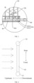
- the first pipe 10 includes a circumferential wall and a main channel 101 surrounded by the circumferential wall.
- the heat exchanger 1 further includes an inlet/outlet pipe 60, and the inlet/outlet pipe 60 is connected to the first pipe 10.
- both the first pipe 10 and the second pipe 20 extend in a left-right direction, and the first pipe 10 and the second pipe 20 are spaced apart in a front-rear direction.
- the inlet/outlet pipe 60 is located on the right side of the first pipe 10, and a right end of the first pipe 10 is connected to a left end of the inlet/outlet pipe 60.
- the heat exchange tube 30 is connected to the first pipe 10, and the other end of the heat exchange tube 30 is connected to the second pipe 20.
- the heat exchange tube 30 is connected to the first pipe 10 and the second pipe 20.
- the heat exchange tube 30 includes a plurality of channels 301 (two or more channels 301) arranged to be spaced apart.
- the channel 301 is connected to the first pipe 10 and the second pipe 20. Flow cross-sectional areas of every two of at least three channels 301 in the plurality of channels 301 are not equal to each other on a cross section of the heat exchange tube 30, and the plurality of channels 301 include a first channel and a second channel.
- a flow cross-sectional area of the first channel is greater than a flow cross-sectional area of another channel 301 different from the first channel in the plurality of channels 301, and a flow cross-sectional area of the second channel is less than a flow cross-sectional area of another channel 301 different from the second channel in the plurality of channels 301.
- each heat exchange tube 30 extends in the front-rear direction, and the plurality of heat exchange tubes 30 are arranged to be spaced apart between the first pipe 10 and the second pipe 20 in the left-right direction.
- a front end of the heat exchange tube 30 is connected to the first pipe 10, and a rear end of the heat exchange tube 30 is connected to the second pipe 20.
- each heat exchange tube 30 is formed with a plurality of channels 301 arranged to be spaced apart in an up-down direction, and the channel 301 extends in the front-rear direction.
- a front end of the channel 301 is connected to the first pipe 10, and a rear end of the channel 301 is connected to the second pipe 20.
- a channel 301 of the plurality of channels 301 that has a largest flow cross-sectional area is a first channel
- a channel 301 of the plurality of channels 301 that has a smallest flow cross-sectional area is a second channel. It should be noted that, in this technical solution, there may be a plurality of first channels and a plurality of second channels, and flow cross-sectional areas of the plurality of channels 301 may be completely different or partially the same.
- the first member 40 is located in the main channel 101 of the first pipe 10, and the first member 40 extends by a specific distance along a length direction of the first pipe 10. A length of the first member 40 in the main channel 101 of the first pipe 10 is less than or equal to a length of the first pipe 10.
- the main channel 101 includes a first flow channel 1011 and a second flow channel 1012, and the first member 40 is located between the first flow channel 1011 and the second flow channel 1012.
- the first flow channel 1011 is connected to the inlet/outlet pipe 60, and the second flow channel 1012 is connected to the heat exchange tube 30.
- the first member 40 includes a plurality of through-holes 401, and the through-hole 401 connects the first flow channel 1011 and the second flow channel 1012.
- the first member 40 penetrates through the main channel 101 in the left-right direction, and the first member 40 is provided with through-holes 401 spaced apart in the left-right direction. Both the first flow channel 1011 and the second flow channel 1012 extend in the left-right direction, and the first member 40 separates the first flow channel 1011 from the second flow channel 1012. A right end of the first flow channel 1011 is connected to the inlet/outlet pipe, and the second flow channel 1012 is connected to front ends of the plurality of heat exchange tubes 30.
- refrigerant may flow into the first flow channel 1011 along the inlet/outlet pipe, and the refrigerant in the first flow channel 1011 flows into the second flow channel 1012 through the through-holes 401 on the first member 40, and flows into the heat exchange tube 30 through connection between the second flow channel 1012 and the heat exchange tube 30 for further heat exchange.
- the flow cross-sectional area of the first channel on the cross section of the heat exchange tube 30 is A1
- the flow cross-sectional area of the second channel on the cross section of the heat exchange tube 30 is A2
- the A1 and A2 satisfy the following expression: 0.15 ⁇ (A1-A2)*N/A3 ⁇ 3.8.
- A3 is a sum of flow cross-sectional areas of the plurality of through-holes 401 of the first member 40
- N is a quantity of the heat exchange tubes 30 connected to the main channel 101.
- the first member 40 (such as a distribution pipe) is not provided in the main channel, and flow cross-sectional areas of the plurality of channels in the heat exchange tube are consistent.
- a heat exchanger in related technologies has problems of uneven distribution of refrigerant in the heat exchange tubes and low heat exchange efficiency. As shown in FIG. 15, FIG. 16 , and FIG. 18 , it is found by the applicant that when the first member is arranged in the main channel and flow cross-sectional areas of the plurality of channels in the heat exchange tube are inconsistent, it helps improve heat exchange performance of the heat exchanger, and balance a degree of superheat at an outlet of the heat exchanger.
- a larger difference between flow cross-sectional areas of the plurality of channels in the heat exchange tube for example, a larger flow cross-sectional area difference between the channel with the largest flow cross-sectional area and the channel with the smallest flow cross-sectional area, better helps improve heat exchange performance.
- a total area of the through-holes on the first member is related to the distribution of the refrigerant in the heat exchange tubes.
- the area of the through-holes affects a flow rate of the refrigerant flowing out of the first member. A larger flow rate better helps evenly mix gas-liquid two-phase refrigerant and better helps improve heat exchange performance.
- the area of the through-hole on the first member needs to be designed based on a status of the heat exchanger.
- the first member distributes refrigerant in the first pipe, and if there is no more refrigerant entering the channel with the largest flow cross-sectional area or refrigerant is evenly distributed among the channels of the heat exchange tube, it is detrimental to heat exchange performance.
- distribution of the refrigerant in the first pipe is not even, through design of the channels of the heat exchange tube, distribution of the refrigerant in the channels of the heat exchange tube can adjust a degree of superheat of the refrigerant at the outlet of the heat exchanger and mitigate impact on heat exchange performance.
- the channel with the largest flow cross-sectional area is used as the first channel
- the flow cross-sectional area of the first channel is defined as A1
- the channel with the smallest flow cross-sectional area is used as the second channel
- the flow cross-sectional area of the second channel is defined as A2
- the quantity of heat exchange tubes connected to the main channel is N
- the sum of the flow cross-sectional areas of the plurality of through-holes of the first member is A3
- the first member is arranged in the main channel of the first pipe to define the first flow channel and the second flow channel in the main channel, and flow cross-sectional areas of the plurality of channels in the heat exchange tube are inconsistent, so that the flow cross-sectional area A1 of the first channel on the cross section of the heat exchange tube, the flow cross-sectional area A2 of the second channel on the cross section of the heat exchange tube, and the quantity N of heat exchange tubes connected to the second flow channel satisfy: 0.15 ⁇ (A1-A2)*N/A3 ⁇ 3.8.
- the first member 40 is a third pipe (a distribution pipe), and the third pipe includes a third circumferential wall.
- the third circumferential wall is located between the first flow channel 1011 and the second flow channel 1012, and the third circumferential wall has through-holes 401 penetrating through the circumferential wall.
- the through-hole 401 connects the first flow channel 1011 and the second flow channel 1012, and the third pipe is connected to the inlet/outlet pipe 60 or the third pipe includes the inlet/outlet pipe.
- the third pipe is a round pipe and penetrates through the main channel 101 in the left-right direction.
- a length of a section of the third pipe is equal to a length of the first pipe 10.
- the circumferential wall of the third pipe has the through-holes 401 that are spaced apart in the left-right direction and that penetrate through the circumferential wall.
- the second flow channel 1012 is formed between the circumferential wall of the third pipe and an inner circumferential wall of the first pipe 10, the first flow channel 1011 (a third channel of the third pipe) is formed in the third pipe, and the first flow channel 1011 and the second flow channel 1012 are connected through the through-hole 401.
- refrigerant flows into the first flow channel 1011 along the inlet/outlet pipe 60, and the refrigerant in the first flow channel 1011 flows into the second flow channel 1012 through the through-holes 401 on the third pipe, and flows into the heat exchange tube 30 through connection between the second flow channel 1012 and the heat exchange tube 30.
- the refrigerant is in the heat exchanger 1 for heat exchange.
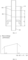
- a side of the heat exchanger 1 located upstream in a wind direction during heat exchange is defined as a windward side
- a downstream side of the wind direction of the heat exchanger 1 is defined as a leeward side.
- a side of through-holes 401 located upstream is the windward side
- a side of through-holes 401 located downstream is the leeward side.
- a direction facing an inlet of a channel of the heat exchange tube 30 is considered 0 degrees.
- An angle formed between a through-hole 401 located upstream and an inlet direction of the channel 301 of the heat exchange tube 30 is considered as a1.
- An angle formed between a through-hole 401 located downstream and the inlet direction of the channel 301 of the heat exchange tube 30 is considered as a2.
- An angle range of a1 is 0 to 180 degrees (including 0 degrees and 180 degrees), and an angle range of a2 is 180 to 360 degrees.
- the first channel in the plurality of channels 301 is located on the windward side, and at least some of the plurality of through-holes are located on the leeward side. Therefore, flow resistance of the refrigerant passing through the first channel is relatively small, so that more refrigerant can flow to the windward side, and a temperature difference between the air flow on the windward side and the refrigerant is large, thereby improving heat exchange performance.
- a sum of flow cross-sectional areas of channels located on the windward side among the plurality of channels 301 is greater than a sum of flow cross-sectional areas of channels located on the leeward side among the plurality of channels 301, and at least some of the plurality of through-holes 401 are located on the leeward side.
- the wind may blow through the heat exchange tubes 30 from upstream to downstream.
- the first channel is located upstream on the windward side, and some of the plurality of through-holes 401 are located downstream on the leeward side.
- some channels with a smaller sum of flow cross-sectional areas can be arranged on the leeward side of the heat exchange tube, other channels with a larger sum of flow cross-sectional areas can be arranged on the windward side of the heat exchange tube, and at least some of the through-holes are arranged on the leeward side of the heat exchange tube.
- Rebounding of an inner wall of the first pipe can be utilized, to help more refrigerant flow to the windward side, so as to adjust a degree of superheat at the outlet of the heat exchanger, and improve heat exchange performance of the heat exchanger.
- all the through-holes 401 are located on the leeward side, and heat exchange performance of the heat exchanger is better.
- some through-holes of the plurality of through-holes 401 of the third pipe are located on the windward side, other through-holes of the plurality of through-holes 401 are located on the leeward side, and a sum of flow cross-sectional areas of the through-holes 401 on the windward side is less than a sum of flow cross-sectional areas of the through-holes 401 on the leeward side.
- some through-holes with a smaller sum of flow cross-sectional areas can be arranged on the leeward side of the heat exchange tube, and other through-holes with a larger sum of flow cross-sectional areas can be arranged on the windward side of the heat exchange tube.
- This can increase a through-hole area on the windward side and reduce a through-hole area on the leeward side, thereby allowing more refrigerant to flow to the windward side, reducing a difference between degrees of superheat of refrigerant on the windward side and the leeward side, improving refrigerant distribution of the heat exchanger, and improving heat exchange performance of the heat exchanger.
- (A1-A2)/A4 ⁇ 0.09 where A4 is a largest flow cross-sectional area of the third pipe.
- A4 is a largest flow cross-sectional area of the third pipe.
- a distance I between at least two adjacent through-holes 401 satisfies: 20 mm ⁇ I ⁇ 150 mm. Therefore, a quantity of the through-holes 401 can be properly set, to avoid that a total area of the through-holes is too large or too small, and improve reliability and uniformity of refrigerant distribution by the third pipe. For example, when 20 mm ⁇ I ⁇ 150 mm, a distribution effect of the refrigerant is better.
- the plurality of channels 301 are evenly spaced, that is, thicknesses of a spacing wall between the through-holes are equal, so as to further optimize distribution of the refrigerant in the heat exchange tube 30.
Landscapes
- Engineering & Computer Science (AREA)
- Physics & Mathematics (AREA)
- Thermal Sciences (AREA)
- Mechanical Engineering (AREA)
- General Engineering & Computer Science (AREA)
- Geometry (AREA)
- Heat-Exchange Devices With Radiators And Conduit Assemblies (AREA)
Claims (13)
- Ein Wärmetauscher (1), der folgende Merkmale aufweist:ein erstes Rohr (10) und ein zweites Rohr (20), wobei das erste Rohr (10) eine Umfangswand und einen Hauptkanal (101) aufweist, der von der Umfangswand umgeben ist, der Wärmetauscher (1) ferner ein Einlass-/Auslassrohr (60) aufweist, und das Einlass-/Auslassrohr (60) mit dem ersten Rohr (10) verbunden ist;eine Mehrzahl von Wärmetauschröhren (30), wobei die Wärmerauschröhre (30) mit dem ersten Rohr (10) und dem zweiten Rohr (20) verbunden ist, die Wärmetauschröhre (30) eine Mehrzahl von Kanälen (301) aufweist, die so angeordnet sind, dass dieselben voneinander beabstandet sind, der Kanal (301) mit dem ersten Rohr (10) und dem zweiten Rohr (20) verbunden ist, Strömungsquerschnittsflächen von jeweils zwei von zumindest drei Kanälen in der Mehrzahl von Kanälen (301) auf einem Querschnitt der Wärmetauschröhre (30) nicht gleich sind, und die Mehrzahl von Kanälen (301) einen ersten Kanal und einen zweiten Kanal aufweist; und auf dem Querschnitt der Wärmetauschröhre (30) eine Strömungsquerschnittsfläche des ersten Kanals größer ist als eine Strömungsquerschnittsfläche eines anderen Kanals, der sich von dem ersten Kanal in der Mehrzahl von Kanälen (301) unterscheidet, und eine Strömungsquerschnittsfläche des zweiten Kanals kleiner ist als eine Strömungsquerschnittsfläche eines anderen Kanals, der sich von dem zweiten Kanal in der Mehrzahl von Kanälen (301) unterscheidet; wobei der Wärmetauscher gekennzeichnet ist durchein erstes Bauglied (40), wobei das erste Bauglied (40) sich in dem Hauptkanal (101) des ersten Rohrs (10) befindet, das erste Bauglied (40) sich um einen spezifischen Abstand entlang einer Längsrichtung des ersten Rohrs (10) erstreckt, der Hauptkanal (101) einen ersten Strömungskanal (1011) und einen zweiten Strömungskanal (1012) aufweist, das erste Bauglied (40) sich zwischen dem ersten Strömungskanal (1011) und dem zweiten Strömungskanal (1012) befindet, der erste Strömungskanal (1011) mit dem Einlass-/Auslassrohr (60) verbunden ist, der zweite Strömungskanal (1012) mit der Wärmetauschröhre (30) verbunden ist, das erste Bauglied (40) eine Mehrzahl von Durchgangslöchern (401) aufweist, und das Durchgangsloch (401) den ersten Strömungskanal (1011) und den zweiten Strömungskanal (1012) verbindet,wobei die Strömungsquerschnittsfläche des ersten Kanals auf dem Querschnitt der Wärmetauschröhre (30) A1 ist, die Strömungsquerschnittsfläche des zweiten Kanals auf dem Querschnitt der Wärmetauschröhre (30) A2 ist, und A1 und A2 den folgenden Ausdruck erfüllen: 0,15 ≤ (A1-A2)*N/A3 ≤ 3,8, wobei A3 eine Summe von Strömungsquerschnittsflächen der Mehrzahl von Durchgangslöchern (401) des ersten Bauglieds (40) ist, und N eine Menge der Wärmetauschröhren (30) ist, die mit dem Hauptkanal (101) verbunden sind.
- Der Wärmetauscher (1) gemäß Anspruch 1, wobei das erste Bauglied (40) ein drittes Rohr ist, das dritte Rohr eine dritte Umfangswand aufweist, die dritte Umfangswand sich zwischen dem ersten Strömungskanal (1011) und dem zweiten Strömungskanal (1012) befindet, die dritte Umfangswand die Durchgangslöcher (401) aufweist, die die Umfangswand durchdringen, das Durchgangsloch (401) den ersten Strömungskanal (1011) und den zweiten Strömungskanal (1012) verbindet, und das dritte Rohr mit dem Einlass-/Auslassrohr (60) verbunden ist, oder das dritte Rohr das Einlass-/Auslassrohr (60) aufweist.
- Der Wärmetauscher (1) gemäß Anspruch 2, wobei eine Seite des Wärmetauschers (1), die sich stromaufwärts in einer Windrichtung während des Wärmeaustauschs befindet, als eine Luvseite definiert ist, eine stromabwärtige Seite der Windrichtung des Wärmetauschers (1) als eine Leeseite definiert ist, und der erste Kanal sich auf der Luvseite befindet.
- Der Wärmetauscher (1) gemäß Anspruch 2, wobei eine Seite des Wärmetauschers (1), die sich stromaufwärts in einer Windrichtung während des Wärmeaustauschs befindet, als eine Luvseite definiert ist, eine stromabwärtige Seite der Windrichtung des Wärmetauschers (1) als eine Leeseite definiert ist, und eine Summe von Strömungsquerschnittsflächen von Kanälen, die sich auf der Luvseite unter der Mehrzahl von Kanälen (301) der Wärmetauschröhre (30) befinden, größer ist als eine Summe von Strömungsquerschnittsflächen von Kanälen, die sich auf der Leeseite unter der Mehrzahl von Kanälen (301) befinden.
- Der Wärmetauscher (1) gemäß Anspruch 3 oder 4, wobei einige Durchgangslöcher der Mehrzahl von Durchgangslöchern (401) in dem dritten Rohr sich auf der Luvseite befinden, andere Durchgangslöcher der Mehrzahl von Durchgangslöchern (401) in dem dritten Rohr sich auf der Leeseite befinden, und eine Summe von Strömungsquerschnittsflächen der Durchgangslöcher (401) auf der Luvseite kleiner ist als eine Summe von Strömungsquerschnittsflächen der Durchgangslöcher (401) auf der Leeseite.
- Der Wärmetauscher (1) gemäß einem der Ansprüche 2 bis 5, wobei (A1-A2)/A4 ≤ 0,09, und A4 eine größte Strömungsquerschnittsfläche des dritten Rohrs ist.
- Der Wärmetauscher (1) gemäß einem der Ansprüche 2 bis 6, wobei ein Abstand I zwischen zumindest zwei benachbarten Durchgangslöchern (401) in einer Längsrichtung des dritten Rohrs Folgendes erfüllt: 20 mm ≤ I ≤ 150 mm.
- Der Wärmetauscher (1) gemäß einem der Ansprüche 2 bis 7, wobei das erste Rohr (10) eine erste Endfläche (50) aufweist, ein Durchgangsloch der Mehrzahl von Durchgangslöchern (401), das benachbart zu der ersten Endfläche (50) des ersten Rohrs (10) in der Längsrichtung des ersten Rohrs (10) ist, ein erstes Durchgangsloch ist, eine Wärmetauschröhre der Mehrzahl von Wärmetauschröhren (30), die benachbart zu der ersten Endfläche (50) des ersten Rohrs (10) ist, eine erste Wärmetauschröhre ist, die Mehrzahl von Wärmetauschröhren (30) eine zweite Wärmetauschröhre aufweist, eine Menge von Wärmetauschröhren (30), die sich zwischen der ersten Wärmetauschröhre und der zweiten Wärmetauschröhre in der Längsrichtung des ersten Rohrs (10) befindet, größer als oder gleich 10 und kleiner als 30 ist, und ein kleinster Abstand zwischen dem ersten Durchgangsloch und der ersten Endfläche (50) in der Längsrichtung des ersten Rohrs (10) kleiner ist als ein kleinster Abstand zwischen der zweiten Wärmetauschröhre und der ersten Endfläche (50) in der Längsrichtung des ersten Rohrs (10).
- Der Wärmetauscher (1) gemäß einem der Ansprüche 1 bis 8, wobei auf dem Querschnitt der Wärmetauschröhre (30) Abstände zwischen zwei benachbarten Kanälen (301) in einer Breitenrichtung der Wärmetauschröhre (30) gleich sind, und Strömungsquerschnittsflächen der zwei benachbarten Kanäle (301) nicht gleich sind.
- Der Wärmetauscher (1) gemäß einem der Ansprüche 1 bis 9, wobei eine äußere Umfangskontur des Querschnitts der Wärmetauschröhre (30) ungefähr viereckig ist, und ein Innendurchmesser des zweiten Rohrs (20) das 1,1-fache oder mehr einer Breite der Wärmetauschröhre (30) beträgt.
- Der Wärmetauscher (1) gemäß Anspruch 3 oder 4, wobei zumindest einige der Durchgangslöcher (401) sich auf der Leeseite befinden.
- Der Wärmetauscher (1) gemäß Anspruch 2, wobei ein Ende des dritten Rohrs mit dem Einlass-/Auslassrohr (60) verbunden ist, das andere Ende des dritten Rohrs ein Loch aufweist, und eine Strömungsquerschnittsfläche des Lochs kleiner ist als eine Strömungsquerschnittsfläche des dritten Rohrs.
- Der Wärmetauscher (1) gemäß einem der Ansprüche 1 bis 12, wobei ein hydraulischer Durchmesser des zweiten Rohrs (20) größer oder gleich dem 1,1-fachen eines hydraulischen Durchmessers des ersten Rohrs (10) ist.
Applications Claiming Priority (1)
| Application Number | Priority Date | Filing Date | Title |
|---|---|---|---|
| PCT/CN2020/101966 WO2022011570A1 (zh) | 2020-07-14 | 2020-07-14 | 换热器 |
Publications (3)
| Publication Number | Publication Date |
|---|---|
| EP4184084A1 EP4184084A1 (de) | 2023-05-24 |
| EP4184084A4 EP4184084A4 (de) | 2024-03-13 |
| EP4184084B1 true EP4184084B1 (de) | 2025-03-05 |
Family
ID=79555981
Family Applications (1)
| Application Number | Title | Priority Date | Filing Date |
|---|---|---|---|
| EP20945496.6A Active EP4184084B1 (de) | 2020-07-14 | 2020-07-14 | Wärmetauscher |
Country Status (5)
| Country | Link |
|---|---|
| US (1) | US12215932B2 (de) |
| EP (1) | EP4184084B1 (de) |
| CN (1) | CN215491193U (de) |
| PL (1) | PL4184084T3 (de) |
| WO (1) | WO2022011570A1 (de) |
Families Citing this family (4)
| Publication number | Priority date | Publication date | Assignee | Title |
|---|---|---|---|---|
| CN116972454A (zh) * | 2022-04-21 | 2023-10-31 | 杭州三花微通道换热器有限公司 | 一种换热系统 |
| CN118111268A (zh) * | 2022-11-30 | 2024-05-31 | 杭州三花微通道换热器有限公司 | 一种换热管及具有该换热管的换热器 |
| CN116045696A (zh) * | 2023-01-17 | 2023-05-02 | 广东美的暖通设备有限公司 | 换热构件、换热器及空调系统 |
| CN118999234A (zh) * | 2023-05-18 | 2024-11-22 | 浙江盾安人工环境股份有限公司 | 一种扁管及具有其的换热器 |
Family Cites Families (18)
| Publication number | Priority date | Publication date | Assignee | Title |
|---|---|---|---|---|
| KR100518856B1 (ko) * | 2003-09-04 | 2005-09-30 | 엘지전자 주식회사 | 플랫 튜브 열 교환기 |
| ES2384185T3 (es) * | 2006-10-13 | 2012-07-02 | Carrier Corporation | Método y aparato para mejorar la distribución de fluido en un intercambiador de calor |
| CN101858698A (zh) * | 2009-04-10 | 2010-10-13 | 三花丹佛斯(杭州)微通道换热器有限公司 | 微通道热交换器 |
| CN101526322A (zh) * | 2009-04-13 | 2009-09-09 | 三花丹佛斯(杭州)微通道换热器有限公司 | 一种扁管及热交换器 |
| US20110240276A1 (en) * | 2010-04-01 | 2011-10-06 | Delphi Technologies, Inc. | Heat exchanger having an inlet distributor and outlet collector |
| CN102287969A (zh) * | 2011-06-16 | 2011-12-21 | 广东美的电器股份有限公司 | 平行流换热器 |
| JP6015229B2 (ja) * | 2012-08-10 | 2016-10-26 | ダイキン工業株式会社 | 熱交換器 |
| US9746255B2 (en) * | 2012-11-16 | 2017-08-29 | Mahle International Gmbh | Heat pump heat exchanger having a low pressure drop distribution tube |
| CN203731744U (zh) * | 2013-12-27 | 2014-07-23 | 无锡佳龙换热器股份有限公司 | 一种稳固的平行流换热器 |
| EP3537088B1 (de) * | 2014-08-19 | 2022-10-26 | Carrier Corporation | Mikrokanalwärmetauscher mit niedriger kühlmittelladung |
| CN105352345B (zh) * | 2015-11-16 | 2017-07-28 | Tcl空调器(中山)有限公司 | 微通道换热器及其空调器 |
| US11614260B2 (en) * | 2017-05-05 | 2023-03-28 | Carrier Corporation | Heat exchanger for heat pump applications |
| JP6906141B2 (ja) * | 2017-10-19 | 2021-07-21 | パナソニックIpマネジメント株式会社 | 熱交換器分流器 |
| US10760835B2 (en) * | 2018-09-05 | 2020-09-01 | Audi Ag | Evaporator in a refrigerant circuit E |
| US12044480B2 (en) * | 2019-02-04 | 2024-07-23 | Mitsubishi Electric Corporation | Heat exchanger and air-conditioning apparatus including the same |
| CN210128650U (zh) * | 2019-05-31 | 2020-03-06 | 杭州三花微通道换热器有限公司 | 扁管、多通道换热器和空调制冷系统 |
| CN210512739U (zh) * | 2019-08-29 | 2020-05-12 | 青岛海信日立空调系统有限公司 | 一种微通道换热器及空调 |
| CN210689278U (zh) * | 2019-09-29 | 2020-06-05 | 杭州三花微通道换热器有限公司 | 多通道换热器和空调制冷系统 |
-
2020
- 2020-07-14 WO PCT/CN2020/101966 patent/WO2022011570A1/zh not_active Ceased
- 2020-07-14 EP EP20945496.6A patent/EP4184084B1/de active Active
- 2020-07-14 PL PL20945496.6T patent/PL4184084T3/pl unknown
- 2020-07-14 CN CN202090000336.7U patent/CN215491193U/zh active Active
-
2022
- 2022-08-31 US US17/823,536 patent/US12215932B2/en active Active
Also Published As
| Publication number | Publication date |
|---|---|
| CN215491193U (zh) | 2022-01-11 |
| US20220412660A1 (en) | 2022-12-29 |
| EP4184084A4 (de) | 2024-03-13 |
| PL4184084T3 (pl) | 2025-06-23 |
| US12215932B2 (en) | 2025-02-04 |
| WO2022011570A1 (zh) | 2022-01-20 |
| EP4184084A1 (de) | 2023-05-24 |
Similar Documents
| Publication | Publication Date | Title |
|---|---|---|
| US12215932B2 (en) | Heat exchanger | |
| US9995303B2 (en) | Air conditioner | |
| US20220333833A1 (en) | Multi-channel heat exchanger and air conditioning refrigeration system | |
| US20060237178A1 (en) | Heat exchanger | |
| US20170102007A1 (en) | Air management system for the outdoor unit of a residential air conditioner or heat pump | |
| US10514216B2 (en) | Heat exchanger | |
| US9618269B2 (en) | Heat exchanger with tube arrangement for air conditioner | |
| US12298086B2 (en) | Heat exchanger and air conditioning unit with multiple refrigeration systems | |
| EP2402701A1 (de) | Wärmetauscher | |
| CN1851372B (zh) | 热交换器 | |
| EP2097707B1 (de) | Wärmetauscherausführung für verbesserte leistung und herstellbarkeit | |
| CN115244356B (zh) | 换热器 | |
| JP2013002688A (ja) | パラレルフロー型熱交換器及びそれを搭載した空気調和機 | |
| WO2019239445A1 (ja) | 冷媒分配器、熱交換器及び空気調和装置 | |
| US20050205244A1 (en) | Heat exchanger | |
| AU2019222790B2 (en) | Pneumatic radiation air conditioner | |
| CN210128532U (zh) | 多制冷系统空调机组 | |
| CN210119132U (zh) | 用于换热器的翅片、换热器及空调室外机 | |
| CN114659168B (zh) | 换热组件和空调器 | |
| CN108534395B (zh) | 换热器和具有其的空调器 | |
| US20250314436A1 (en) | Air conditioner having refrigerant distributor | |
| CN218672404U (zh) | 翅片、换热器以及空调室内机 | |
| TWI809718B (zh) | 熱交換器及冷凍循環裝置 | |
| CN210119145U (zh) | 换热器和具有其的制冷设备 | |
| CN120444940A (zh) | 一种换热器及换热装置 |
Legal Events
| Date | Code | Title | Description |
|---|---|---|---|
| STAA | Information on the status of an ep patent application or granted ep patent |
Free format text: STATUS: THE INTERNATIONAL PUBLICATION HAS BEEN MADE |
|
| PUAI | Public reference made under article 153(3) epc to a published international application that has entered the european phase |
Free format text: ORIGINAL CODE: 0009012 |
|
| STAA | Information on the status of an ep patent application or granted ep patent |
Free format text: STATUS: REQUEST FOR EXAMINATION WAS MADE |
|
| 17P | Request for examination filed |
Effective date: 20220831 |
|
| AK | Designated contracting states |
Kind code of ref document: A1 Designated state(s): AL AT BE BG CH CY CZ DE DK EE ES FI FR GB GR HR HU IE IS IT LI LT LU LV MC MK MT NL NO PL PT RO RS SE SI SK SM TR |
|
| DAV | Request for validation of the european patent (deleted) | ||
| DAX | Request for extension of the european patent (deleted) | ||
| A4 | Supplementary search report drawn up and despatched |
Effective date: 20240213 |
|
| RIC1 | Information provided on ipc code assigned before grant |
Ipc: F28F 1/02 20060101ALI20240207BHEP Ipc: F25B 39/00 20060101AFI20240207BHEP |
|
| GRAP | Despatch of communication of intention to grant a patent |
Free format text: ORIGINAL CODE: EPIDOSNIGR1 |
|
| STAA | Information on the status of an ep patent application or granted ep patent |
Free format text: STATUS: GRANT OF PATENT IS INTENDED |
|
| INTG | Intention to grant announced |
Effective date: 20240930 |
|
| GRAS | Grant fee paid |
Free format text: ORIGINAL CODE: EPIDOSNIGR3 |
|
| GRAA | (expected) grant |
Free format text: ORIGINAL CODE: 0009210 |
|
| STAA | Information on the status of an ep patent application or granted ep patent |
Free format text: STATUS: THE PATENT HAS BEEN GRANTED |
|
| P01 | Opt-out of the competence of the unified patent court (upc) registered |
Free format text: CASE NUMBER: APP_2920/2025 Effective date: 20250117 |
|
| AK | Designated contracting states |
Kind code of ref document: B1 Designated state(s): AL AT BE BG CH CY CZ DE DK EE ES FI FR GB GR HR HU IE IS IT LI LT LU LV MC MK MT NL NO PL PT RO RS SE SI SK SM TR |
|
| REG | Reference to a national code |
Ref country code: GB Ref legal event code: FG4D |
|
| REG | Reference to a national code |
Ref country code: CH Ref legal event code: EP |
|
| REG | Reference to a national code |
Ref country code: DE Ref legal event code: R096 Ref document number: 602020047455 Country of ref document: DE |
|
| REG | Reference to a national code |
Ref country code: IE Ref legal event code: FG4D |
|
| PG25 | Lapsed in a contracting state [announced via postgrant information from national office to epo] |
Ref country code: RS Free format text: LAPSE BECAUSE OF FAILURE TO SUBMIT A TRANSLATION OF THE DESCRIPTION OR TO PAY THE FEE WITHIN THE PRESCRIBED TIME-LIMIT Effective date: 20250605 |
|
| PG25 | Lapsed in a contracting state [announced via postgrant information from national office to epo] |
Ref country code: FI Free format text: LAPSE BECAUSE OF FAILURE TO SUBMIT A TRANSLATION OF THE DESCRIPTION OR TO PAY THE FEE WITHIN THE PRESCRIBED TIME-LIMIT Effective date: 20250305 |
|
| PGFP | Annual fee paid to national office [announced via postgrant information from national office to epo] |
Ref country code: PL Payment date: 20250627 Year of fee payment: 6 |
|
| REG | Reference to a national code |
Ref country code: NL Ref legal event code: MP Effective date: 20250305 |
|
| PG25 | Lapsed in a contracting state [announced via postgrant information from national office to epo] |
Ref country code: ES Free format text: LAPSE BECAUSE OF FAILURE TO SUBMIT A TRANSLATION OF THE DESCRIPTION OR TO PAY THE FEE WITHIN THE PRESCRIBED TIME-LIMIT Effective date: 20250305 |
|
| REG | Reference to a national code |
Ref country code: LT Ref legal event code: MG9D |
|
| PG25 | Lapsed in a contracting state [announced via postgrant information from national office to epo] |
Ref country code: NO Free format text: LAPSE BECAUSE OF FAILURE TO SUBMIT A TRANSLATION OF THE DESCRIPTION OR TO PAY THE FEE WITHIN THE PRESCRIBED TIME-LIMIT Effective date: 20250605 |
|
| PG25 | Lapsed in a contracting state [announced via postgrant information from national office to epo] |
Ref country code: HR Free format text: LAPSE BECAUSE OF FAILURE TO SUBMIT A TRANSLATION OF THE DESCRIPTION OR TO PAY THE FEE WITHIN THE PRESCRIBED TIME-LIMIT Effective date: 20250305 |
|
| PG25 | Lapsed in a contracting state [announced via postgrant information from national office to epo] |
Ref country code: LV Free format text: LAPSE BECAUSE OF FAILURE TO SUBMIT A TRANSLATION OF THE DESCRIPTION OR TO PAY THE FEE WITHIN THE PRESCRIBED TIME-LIMIT Effective date: 20250305 |
|
| PG25 | Lapsed in a contracting state [announced via postgrant information from national office to epo] |
Ref country code: BG Free format text: LAPSE BECAUSE OF FAILURE TO SUBMIT A TRANSLATION OF THE DESCRIPTION OR TO PAY THE FEE WITHIN THE PRESCRIBED TIME-LIMIT Effective date: 20250305 Ref country code: GR Free format text: LAPSE BECAUSE OF FAILURE TO SUBMIT A TRANSLATION OF THE DESCRIPTION OR TO PAY THE FEE WITHIN THE PRESCRIBED TIME-LIMIT Effective date: 20250606 |
|
| REG | Reference to a national code |
Ref country code: AT Ref legal event code: MK05 Ref document number: 1773232 Country of ref document: AT Kind code of ref document: T Effective date: 20250305 |
|
| PG25 | Lapsed in a contracting state [announced via postgrant information from national office to epo] |
Ref country code: NL Free format text: LAPSE BECAUSE OF FAILURE TO SUBMIT A TRANSLATION OF THE DESCRIPTION OR TO PAY THE FEE WITHIN THE PRESCRIBED TIME-LIMIT Effective date: 20250305 |
|
| PG25 | Lapsed in a contracting state [announced via postgrant information from national office to epo] |
Ref country code: SE Free format text: LAPSE BECAUSE OF FAILURE TO SUBMIT A TRANSLATION OF THE DESCRIPTION OR TO PAY THE FEE WITHIN THE PRESCRIBED TIME-LIMIT Effective date: 20250305 |
|
| PG25 | Lapsed in a contracting state [announced via postgrant information from national office to epo] |
Ref country code: SM Free format text: LAPSE BECAUSE OF FAILURE TO SUBMIT A TRANSLATION OF THE DESCRIPTION OR TO PAY THE FEE WITHIN THE PRESCRIBED TIME-LIMIT Effective date: 20250305 |
|
| PG25 | Lapsed in a contracting state [announced via postgrant information from national office to epo] |
Ref country code: PT Free format text: LAPSE BECAUSE OF FAILURE TO SUBMIT A TRANSLATION OF THE DESCRIPTION OR TO PAY THE FEE WITHIN THE PRESCRIBED TIME-LIMIT Effective date: 20250707 |
|
| PGFP | Annual fee paid to national office [announced via postgrant information from national office to epo] |
Ref country code: DE Payment date: 20250711 Year of fee payment: 6 |
|
| PGFP | Annual fee paid to national office [announced via postgrant information from national office to epo] |
Ref country code: IT Payment date: 20250708 Year of fee payment: 6 |
|
| PG25 | Lapsed in a contracting state [announced via postgrant information from national office to epo] |
Ref country code: AT Free format text: LAPSE BECAUSE OF FAILURE TO SUBMIT A TRANSLATION OF THE DESCRIPTION OR TO PAY THE FEE WITHIN THE PRESCRIBED TIME-LIMIT Effective date: 20250305 |
|
| PGFP | Annual fee paid to national office [announced via postgrant information from national office to epo] |
Ref country code: FR Payment date: 20250730 Year of fee payment: 6 |
|
| PG25 | Lapsed in a contracting state [announced via postgrant information from national office to epo] |
Ref country code: CZ Free format text: LAPSE BECAUSE OF FAILURE TO SUBMIT A TRANSLATION OF THE DESCRIPTION OR TO PAY THE FEE WITHIN THE PRESCRIBED TIME-LIMIT Effective date: 20250305 Ref country code: EE Free format text: LAPSE BECAUSE OF FAILURE TO SUBMIT A TRANSLATION OF THE DESCRIPTION OR TO PAY THE FEE WITHIN THE PRESCRIBED TIME-LIMIT Effective date: 20250305 |
|
| PG25 | Lapsed in a contracting state [announced via postgrant information from national office to epo] |
Ref country code: RO Free format text: LAPSE BECAUSE OF FAILURE TO SUBMIT A TRANSLATION OF THE DESCRIPTION OR TO PAY THE FEE WITHIN THE PRESCRIBED TIME-LIMIT Effective date: 20250305 |
|
| PG25 | Lapsed in a contracting state [announced via postgrant information from national office to epo] |
Ref country code: SK Free format text: LAPSE BECAUSE OF FAILURE TO SUBMIT A TRANSLATION OF THE DESCRIPTION OR TO PAY THE FEE WITHIN THE PRESCRIBED TIME-LIMIT Effective date: 20250305 |
|
| PG25 | Lapsed in a contracting state [announced via postgrant information from national office to epo] |
Ref country code: IS Free format text: LAPSE BECAUSE OF FAILURE TO SUBMIT A TRANSLATION OF THE DESCRIPTION OR TO PAY THE FEE WITHIN THE PRESCRIBED TIME-LIMIT Effective date: 20250705 |
|
| REG | Reference to a national code |
Ref country code: DE Ref legal event code: R097 Ref document number: 602020047455 Country of ref document: DE |
|
| PLBE | No opposition filed within time limit |
Free format text: ORIGINAL CODE: 0009261 |
|
| STAA | Information on the status of an ep patent application or granted ep patent |
Free format text: STATUS: NO OPPOSITION FILED WITHIN TIME LIMIT |
|
| PG25 | Lapsed in a contracting state [announced via postgrant information from national office to epo] |
Ref country code: DK Free format text: LAPSE BECAUSE OF FAILURE TO SUBMIT A TRANSLATION OF THE DESCRIPTION OR TO PAY THE FEE WITHIN THE PRESCRIBED TIME-LIMIT Effective date: 20250305 |
|
| REG | Reference to a national code |
Ref country code: CH Ref legal event code: L10 Free format text: ST27 STATUS EVENT CODE: U-0-0-L10-L00 (AS PROVIDED BY THE NATIONAL OFFICE) Effective date: 20260114 |
|
| 26N | No opposition filed |
Effective date: 20251208 |
|
| REG | Reference to a national code |
Ref country code: CH Ref legal event code: H13 Free format text: ST27 STATUS EVENT CODE: U-0-0-H10-H13 (AS PROVIDED BY THE NATIONAL OFFICE) Effective date: 20260224 |
|
| PG25 | Lapsed in a contracting state [announced via postgrant information from national office to epo] |
Ref country code: LU Free format text: LAPSE BECAUSE OF NON-PAYMENT OF DUE FEES Effective date: 20250714 |
|
| GBPC | Gb: european patent ceased through non-payment of renewal fee |
Effective date: 20250714 |