EP4183992A1 - Exzentrisches element und verbrennungsmotor - Google Patents
Exzentrisches element und verbrennungsmotor Download PDFInfo
- Publication number
- EP4183992A1 EP4183992A1 EP21209858.6A EP21209858A EP4183992A1 EP 4183992 A1 EP4183992 A1 EP 4183992A1 EP 21209858 A EP21209858 A EP 21209858A EP 4183992 A1 EP4183992 A1 EP 4183992A1
- Authority
- EP
- European Patent Office
- Prior art keywords
- eccentric member
- wall
- centreline
- gear
- lift
- Prior art date
- Legal status (The legal status is an assumption and is not a legal conclusion. Google has not performed a legal analysis and makes no representation as to the accuracy of the status listed.)
- Withdrawn
Links
- 238000002485 combustion reaction Methods 0.000 title claims abstract description 25
- 230000006835 compression Effects 0.000 claims abstract description 19
- 238000007906 compression Methods 0.000 claims abstract description 19
- 230000005484 gravity Effects 0.000 description 20
- 238000010304 firing Methods 0.000 description 5
- 230000000694 effects Effects 0.000 description 4
- 230000009286 beneficial effect Effects 0.000 description 1
- 230000003247 decreasing effect Effects 0.000 description 1
- 238000005474 detonation Methods 0.000 description 1
Images


Classifications
-
- F—MECHANICAL ENGINEERING; LIGHTING; HEATING; WEAPONS; BLASTING
- F02—COMBUSTION ENGINES; HOT-GAS OR COMBUSTION-PRODUCT ENGINE PLANTS
- F02B—INTERNAL-COMBUSTION PISTON ENGINES; COMBUSTION ENGINES IN GENERAL
- F02B75/00—Other engines
- F02B75/04—Engines with variable distances between pistons at top dead-centre positions and cylinder heads
- F02B75/048—Engines with variable distances between pistons at top dead-centre positions and cylinder heads by means of a variable crank stroke length
-
- F—MECHANICAL ENGINEERING; LIGHTING; HEATING; WEAPONS; BLASTING
- F16—ENGINEERING ELEMENTS AND UNITS; GENERAL MEASURES FOR PRODUCING AND MAINTAINING EFFECTIVE FUNCTIONING OF MACHINES OR INSTALLATIONS; THERMAL INSULATION IN GENERAL
- F16C—SHAFTS; FLEXIBLE SHAFTS; ELEMENTS OR CRANKSHAFT MECHANISMS; ROTARY BODIES OTHER THAN GEARING ELEMENTS; BEARINGS
- F16C3/00—Shafts; Axles; Cranks; Eccentrics
- F16C3/04—Crankshafts, eccentric-shafts; Cranks, eccentrics
- F16C3/22—Cranks; Eccentrics
- F16C3/28—Adjustable cranks or eccentrics
-
- F—MECHANICAL ENGINEERING; LIGHTING; HEATING; WEAPONS; BLASTING
- F16—ENGINEERING ELEMENTS AND UNITS; GENERAL MEASURES FOR PRODUCING AND MAINTAINING EFFECTIVE FUNCTIONING OF MACHINES OR INSTALLATIONS; THERMAL INSULATION IN GENERAL
- F16F—SPRINGS; SHOCK-ABSORBERS; MEANS FOR DAMPING VIBRATION
- F16F15/00—Suppression of vibrations in systems; Means or arrangements for avoiding or reducing out-of-balance forces, e.g. due to motion
- F16F15/28—Counterweights, i.e. additional weights counterbalancing inertia forces induced by the reciprocating movement of masses in the system, e.g. of pistons attached to an engine crankshaft; Attaching or mounting same
- F16F15/283—Counterweights, i.e. additional weights counterbalancing inertia forces induced by the reciprocating movement of masses in the system, e.g. of pistons attached to an engine crankshaft; Attaching or mounting same for engine crankshafts
Definitions
- the present invention relates to an eccentric member to be mounted between a crankpin of a crankshaft and a big end of a connecting rod of an internal combustion engine including variable compression ratio, comprising a cylindrical inner wall having a first centreline, a cylindrical outer wall having a second centreline extending parallel to the first centreline and an annular driving body that is located next to the cylindrical outer wall in axial direction thereof and having a centreline which coincides with the first centreline, wherein the first and second centrelines span a first plane which intersects the outer wall at a line of maximum lift and a line of minimum lift, wherein the first centreline also lies within a second plane that extends perpendicularly to the first plane, which second plane divides the eccentric member in a high-lift section in which the line of maximum lift is located and a low-lift section in which the line of minimum lift is located.
- An internal combustion engine including such an eccentric member is known from EP 3 365 544 .
- the eccentric member gear meshes with a first stage gear.
- the first stage gear is fixed to a second stage gear that has a smaller diameter than the first stage gear.
- the first and second intermediate stage gears are rotatably mounted to a crankshaft of the engine and have a common axis of rotation which extends parallel to a crankshaft axis of the crankshaft.
- the known engine further comprises an actuating gear which meshes with the second stage gear and which is fixed to an actuating shaft that extends through the crankshaft.
- the actuating shaft is rotatable with respect to the crankshaft about the crankshaft axis.
- the actuating shaft has a fixed angular position with respect to a crankcase of the engine.
- the number of teeth of the eccentric member gear, the first and second stage gears and the actuating gear are such that under operating conditions, in case of a standstill of the actuating gear, the eccentric member is rotated with respect to the crankpin at half speed of the speed of the crankshaft with respect to the crankcase and in opposite direction thereof.
- the eccentric member rotates once about the crankpin in opposite direction; as seen from the crankcase the eccentric member rotates once about the centreline of the crankpin in the same rotational direction as the crankshaft.
- a standstill of the actuating gear means that the actuating gear has a fixed position with respect to the crankcase of the internal combustion engine.
- the present invention aims to improve the internal combustion as described above.
- the eccentric member according to the invention is characterized in that the high-lift section is provided with at least a slot which extends in its circumferential direction and/or wherein the low-lift section is provided with a counterweight.
- the centre of gravity of the eccentric member may be shifted in a direction from the high-lift section to the low-lift section with respect to the eccentric member according to the prior art. This provides the opportunity to balance or even overbalance the eccentric member. The latter effect may be desired in order to balance other inertia torque contributions from other engine parts onto the eccentric member.
- the first plane may form a plane of symmetry of the eccentric member such that the effect of the slot and/or the counterweight on the location of the centre of gravity does not shift from the first plane.
- the counterweight may be formed by a widened portion of the annular driving body at the low-lift section.
- the widened portion may be located at a side of the annular driving body where the outer wall is located. In this case at least at the low-lift section the annular driving body projects from the outer wall in radial direction thereof.
- the annular driving body is an eccentric member gear being an outer gear.
- the annular driving body may also be a pully or a sprocket, for example for being driven by means of a belt, toothed belt or a chain.
- the widened portion may comprise a number of extensions of teeth of the eccentric member gear. This means that at least a number of teeth at the low-lift section is wider than at least a number of teeth at the high-lift section.
- the counterweight is located at a side of the annular driving body where the outer wall is located.
- the counterweight may be a partly annular element, which is made of a plate. It may be a separate part.
- the counterweight may be located between the annular driving body and the outer wall as seen in axial direction of the eccentric member.
- the largest part of the slot as measured in its longitudinal direction, and preferably the entire slot, may be located at the high-lift section.
- a slot that also extends into the low-lift section will counteract the intention to shift the centre of gravity in a direction from the line of maximum lift to the line of minimum lift.
- the slot may be in the outer wall.
- the slot is located at an axial end portion of the outer wall.
- the slot may be located next to the annular driving body. This means that the outer wall may be locally narrowed at the high-lift section.
- the slot is located between axial ends of the outer wall.
- the depth of the slot may increases in a direction towards the line of maximum lift. This is possible since the distance between the inner and outer walls increases in a direction towards the line of maximum lift.
- the slot is located between axial ends of the outer wall it may form an opening between the inner wall and the outer wall, such that it also functions as an oil passage when installed between the crankpin and the big end of a connecting rod of an engine.
- the slot is located in the outer wall at an axial end portion of the outer wall and next to the annular driving body and the counterweight is located at substantially the same location in axial direction of the eccentric member.
- the slot narrows a supporting surface for bearing the big end of the connecting rod, whereas the reduced portion is used by the counterweight, i.e. the reduced portion may be filled with a partly annular element as described hereinbefore, for example, or it may be filled with a number of widened teeth in case the annular driving body is an outer gear. This provides a compact balanced eccentric member.
- the slot and/or the counterweight may be adapted such that the centre of gravity of the eccentric member lies on the first centreline or beyond the first centreline as seen from the second centreline. In the latter case the eccentric member is overbalanced and in the former case the eccentric member is entirely balanced.
- the slot may be provided in an axial side of the eccentric member, for example within the annular driving body.
- the invention is also related to an internal combustion engine including variable compression ratio, comprising a crankshaft being rotatable about a crankshaft axis and having a crankpin, wherein the crankshaft axis and a centreline of the crankpin span a crank plane, a connecting rod including a big end and a small end, a piston being rotatably connected to the small end of the connecting rod, an eccentric member as described hereinbefore, being rotatably mounted on the crankpin such that a centreline of the crankpin coincides with the first centreline of the eccentric member, wherein the big end of the connecting rod is rotatably mounted on the outer wall of the eccentric member such that a centreline of the big end coincides with the second centreline of the eccentric member, wherein the annular driving body is drivably coupled to a drive train for rotating the eccentric member with respect to the crankpin at a virtual standstill of the crankshaft.
- the drive train may be adapted such that the eccentric member rotates with respect to the crankpin at half speed of the speed of the crankshaft and in opposite direction thereof.
- the annular driving body is an eccentric member gear being an outer gear
- the drive train comprises an actuating gear which is drivably coupled to the eccentric member gear and fixed to an actuating shaft
- the actuating shaft is rotatably mounted to the crankshaft and rotatable about an axis which coincides with the crankshaft axis, wherein under operating conditions the actuating shaft stands still at fixed compression ratio.
- the drive train may comprise a first stage gear that is fixed to a second stage gear and which has a larger diameter than the second stage gear, wherein the second stage gear meshes with the actuating gear and the first stage gear meshes with the eccentric member gear, whereas the second stage gear has a larger diameter than the actuating gear.
- the first and/or second stage gears may be adapted such that their common centre of gravity is located eccentrically, for example by means of a cavity therein. This allows the first and/or second stage gears to generate a counter torque to the torque which is exerted by the eccentric member onto the first stage gear such that a resulting smaller torque is transferred to the actuating gear under operating conditions.
- the actuating gear may be located at the same side of a crank arm of the crankshaft as the eccentric member gear, whereas the actuating shaft extends through the crankshaft.
- the number of teeth of the eccentric member gear, the first and second stage gears and the actuating gear may be such that under operating conditions the eccentric member rotates with respect to the crankpin at half speed of the speed of the crankshaft and in opposite direction thereof, since the relative motion of the eccentric member and the crankpin, on the one hand, and of the eccentric member and the connecting rod, on the other hand, is relatively small, which minimizes friction losses.
- bearings between the outer wall and the connecting rod and between the eccentric member and the crankpin experience half the crankshaft speed.
- a centre of the outer wall in its axial direction may lie beyond a centre of the inner wall in its axial direction, as seen from the annular driving body.
- Fig. 1 shows an embodiment of a four-stroke internal combustion engine 1 including variable compression ratio according to the invention and Figs. 2 and 3 show parts thereof.
- the engine 1 comprises a crankshaft 2 which is rotatably mounted to a crankcase (not shown) and rotatable about a crankshaft axis 3.
- the crankshaft 2 has a crankpin 4 on which an eccentric member 5 is rotatably mounted.
- the eccentric member 5 is rotatable about a centreline of the crankpin 4 and has a cylindrical outer wall 6 that bears a big end of a connecting rod 7.
- the outer wall 6 is eccentrically disposed with respect to the crankpin 4.
- the internal combustion engine 1 is further provided with a piston 8 which is rotatably connected to a small end of the connecting rod 7.
- the engine 1 has a single cylinder but a multi-cylinder engine is also conceivable.
- the eccentric member 5 is provided with an eccentric member gear 9 which is an outer gear and has an axis of rotation that coincides with the centreline of the crankpin 4.
- the eccentric member 5 is drivably coupled to a gear train 10 for rotating the eccentric member 5 with respect to the crankpin 4 at half speed of the speed of the crankshaft 2 and in opposite direction thereof. This means that if the crankshaft 2 rotates twice about the crankshaft axis 3 in clockwise direction, the eccentric member 5 rotates once about the crankpin 4 in anti-clockwise direction.
- the gear train 10 comprises a first stage gear 11 that meshes with the eccentric member gear 9 and has the same number of teeth as the eccentric member gear 9, a second stage gear 12 which is fixed to the first stage gear 11 and an actuating gear 13 which meshes with the second stage gear 12.
- the first stage gear 11 and the second stage gear 12 are rotatably mounted to the crankshaft 2 and have a common axis of rotation which is parallel to the crankshaft axis 3.
- the first stage gear 11 has a larger diameter and more teeth than the second stage gear 12, whereas the second stage gear 12 has a larger diameter and more teeth than the actuating gear 13.
- the actuating gear 13 is fixed to one end of an actuating shaft 14 that extends through the crankshaft 2.
- the actuating shaft 14 is rotatable with respect to the crankshaft 2 about the crankshaft axis 3.
- a worm wheel 15 is fixed on the actuating shaft 14 at a distance from the actuating gear 13 and meshes with a worm 16 that is drivable by an electric motor 17.
- the eccentric member 5 and the first and second stage gears 11, 12 are located at the same side of a crank arm as the crankpin 4, whereas the worm wheel 15 is located at an opposite side thereof.
- the actuating shaft 14 can be turned by the electric motor 17 in order to vary the compression ratio of the internal combustion engine 1. This provides the opportunity to operate the internal combustion engine 1 at a high compression ratio under low load conditions in order to improve its efficiency. Under high load conditions, the compression ratio can be decreased to avoid detonations. In case of running at fixed compression ratio the actuating shaft 14 has a fixed angular position with respect to the crankcase.
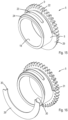
- Figs. 4 and 5 show the eccentric member 5 as a separate part which is mounted between the crankpin 4 and the big end of the connecting rod 7.
- the eccentric member 5 has a cylindrical inner wall 18 which has a first centreline 10.
- the cylindrical outer wall 6 surrounds the cylindrical inner wall 18 and has a second centreline 19 which extends parallel to the first centreline 10.
- the centreline of the eccentric member gear 9 and the first centreline 10 coincide with the centreline of the crankpin 4, whereas a centreline of the big end of the connecting rod 7 coincides with the second centreline 19.
- the eccentric member gear 9 is located next to the cylindrical outer wall 6 in axial direction thereof.
- the first and second centrelines 10, 19 span a first plane which intersects the outer wall 6 at a line of maximum lift 20, where the distance between the inner wall 18 and the outer wall 6 is at its maximum, and a line of minimum lift 21, where the distance between the inner wall 18 and the outer wall 6 is at its minimum.
- a second plane within which the first centreline 10 lies and which extends perpendicularly to the first plane divides the eccentric member 5 in a high-lift section 5a in which the line of maximum lift 20 is located and a low-lift section 5b in which the line of minimum lift 21 is located, see Fig. 5 .
- Figs. 4 and 5 show that the high-lift section 5a is provided with three parallel slots in the outer wall 6: a first slot 22 which is located at an axial end portion of the outer wall 6 next to the eccentric member gear 9, a second slot 23 which is located between axial ends of the outer wall 6 and a third slot 24 which is located at an axial end portion of the outer wall 6 remote from the eccentric member gear 9.
- Each of the first to third slots 22-24 is entirely located at the high-lift section 5a, extends in circumferential direction of the outer wall 6 and is symmetrical with respect to the first plane.
- the second slot 23 forms an opening between the inner wall 18 and the outer wall 6 such that it can function as an oil passage between the crankpin 4 and the big end of the connecting rod 7.
- the first and third slots 22, 24 are longer than the second slot 23 in this case.
- the depths of the first and third slots increase in a direction towards the line of maximum lift 20.
- Fig. 2 shows that the eccentric member also has a fourth slot 28, which is not provided in the outer wall 6, but at an axial side of the eccentric member 5 within the crank member gear 9 at the high-lift section 5a.
- Figs. 4 and 5 show that the eccentric member gear 9 is wider at the low-lift section 5b than at the high-lift section 5a.
- the widened portion forms a counterweight.
- the widened portion comprises extensions of teeth of the eccentric member gear at the low-lift section 5b.
- first to fourth slots 22, 23, 24 and 28 at the high-lift section 5a and the widened eccentric member gear 9 at the low-lift section 5b serve to displace the centre of gravity of the eccentric member 5 in a direction from the second centreline 19 towards the first centreline 10 with respect to a prior art configuration of the eccentric member without the first to fourth slots 22, 23, 24, 28 and the widened eccentric member gear 9. This provides the opportunity to balance the eccentric member gear 5 or even overbalance the eccentric member gear 5 such that its centre of gravity lies at the low-lift section 5b.
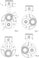
- Figs. 6-10 show successive situations of the engine 1' under operating conditions when the piston 8 moves from top dead centre, where firing starts, to bottom dead centre, where the exhaust stroke starts, and back towards top dead centre where the exhaust stroke ends.
- the figures show that during one revolution of the crankshaft 2 in clockwise direction the eccentric member 5' rotates by a half revolution about the crankpin 4 in anti-clockwise direction.
- Figs. 6-10 show a small circle on the eccentric member 5' which indicates an angular location where the distance between the inner wall 18 and the outer wall 6 has its maximum, i.e. at the line of maximum lift 20 as shown in Fig. 4 .
- Figs. 11 and 12 show the situations as depicted in Figs. 6 and 8 again.
- the location of the centre of gravity of the eccentric member 5' is indicated by CoG, which lies eccentrically with respect to the centreline of the crankpin 4.
- CoG the eccentrical centre of gravity
- the centrifugal force leads to a fluctuating torque on the eccentric member 5' about the centreline of the crankpin 4.
- the fluctuating torque is transferred to the actuating gear 13 via the first and second stage gears 11', 12. Because of the relatively small diameter of the actuating gear 13 the fluctuating torque might lead to overload of its gear teeth, particularly at high engine speed.
- Fig. 11 illustrates a condition at highest compression ratio in which at top dead centre of the piston 8 where firing starts the crankshaft axis 3, the centreline of the crankpin 4 and the centre of gravity CoG of the eccentric member 5' lie in the crank plane, whereas the centreline of the crankpin 4 lies between the crankshaft axis 3 and the centre of gravity CoG. Consequently, the centrifugal force on the eccentric member 5' is directed through the centreline of the crankpin 4, which means that in this situation it does not generate a torque about the centreline of the crankpin 4.
- Fig. 12 shows a situation in which the piston 8 is in bottom dead centre.
- the centre of gravity CoG of the eccentric member 5' lies outside the crank plane that is spanned by the crankshaft axis 3 and the centreline of the crankpin 4.
- the centrifugal force in the centre of gravity CoG which is directed in radial direction from the crankshaft axis 3 generates a torque in clockwise direction which torque is transferred via the eccentric member gear 9 to the first stage gear 11'.
- Figs. 2 and 3 show that the first stage gear 11 is provided with cavities 25 which serve to create an eccentrical centre of gravity thereof. Under operating conditions the eccentrical centre of gravity of the first stage gear 11 generates a centrifugal force on the first stage gear 11, i.e. a torque about an axis of rotation of the first stage gear 11. Since the first stage gear 11 and the eccentric member gear 9 have the same number of teeth and rotate opposite to each other under operating conditions the first stage gear 11 generates a counter torque to the torque which is exerted by the eccentric member 5 onto the first stage gear 11 such that a resulting smaller torque is transferred to the actuating gear 13. This effect is described in more detail by the applicant in European patent applications 20210071.5 and 20216846.4 .
- the invention also provides the opportunity to overbalance the eccentric member 5 in order to create a counter torque against a different inertial force onto the eccentric member 5, for example an inertial force that is generated by the piston 8 and/or the connecting rod 7.
- a different inertial force for example an inertial force that is generated by the piston 8 and/or the connecting rod 7.
- the big end of the connecting rod 7 generates a centrifugal force which is directed from the crankshaft axis 3 to its centre of gravity, which at least partly acts onto the eccentric member 5 through the centreline of the big end.
- This condition would happen in the situation as shown in Fig. 12 , for example.
- the big end can generate a torque on the eccentric member 5 due to a centrifugal force thereof.
- inertial forces onto the eccentric member 5 is inertia of the piston 8 and the connecting rod 7 due to their reciprocating motion, which inertial forces are highest in top dead centre and bottom dead centre of the piston 8.
- inertial forces of the piston 8 and the connecting rod 7 are exerted in downward direction onto the eccentric member 5 and are directed through the centreline of the big end.
- the resulting torque can at least partly be compensated by the eccentric member 5 and/or the first stage gear 11 as described hereinbefore.
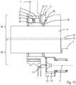
- Figs. 13 and 14 show a part of the engine 1 where the eccentric member 5 is located in greater detail. It can be seen that the eccentric member 5 is supported by the crankpin 4 through an inner needle bearing 26 and that the big end is supported by the eccentric member 5 through an outer needle bearing 27.
- Fig. 13 shows a condition in which the piston 8 is in top dead centre where firing starts and
- Fig. 14 shows a condition in which the piston 8 is in top dead centre where the exhaust strokes ends.
- the width of the eccentric member gear 9 at the low-lift section 5b is slightly larger than the width of the first stage gear 11, see Fig. 13
- the width of the eccentric member gear 9 at the high-lift section 5a is smaller than the width of the first stage gear 11, see Fig. 14 .
- the widened portion of the eccentric member gear 9 meshes with the first stage gear 11 during the last part of the compression stroke and the first part of the combustion stroke this has a beneficial effect on durability of the eccentric member gear 9.
- the widened portion of the eccentric member gear 9 prevents overload of the actuating gear 13 as well as improves durability of the eccentric member gear 9.
- Figs. 13 and 14 show that a centre of the outer wall 6 in its axial direction lies beyond a centre of the inner wall 18 in its axial direction, as seen from the eccentric member gear 9.
- centres of the outer needle bearing 27 and the big end of the connecting rod 7 are shifted outwardly with respect to a centre of the inner needle bearing 26 as seen from the crank member gear 9.
- a gear cage of the outer needle bearing 27 may be located in the big end of the connecting rod 7.
- Figs. 15 and 16 show an alternative embodiment of the eccentric member 5.
- This embodiment is also provided with the first to fourth slots 22, 23, 24 and 28, but it does not have a widened portion of the eccentric member gear 9 at the low-lift section 5b.
- a counterweight in the form of a partly annular element 29, which is mounted as a separate part to an axial side of the eccentric member gear 9 such that it is located between the eccentric member gear 9 and the big end of the connecting rod 7 when mounted on the crankpin 4.
- the partly annular element 29 is located at the low-lift section 5b.
- Opposite ends of the partly annular element 29 comprise respective hooks 30 which fit in cooperating notches 31 at the axial side of the crank member gear 9 which is located at the same side as outer wall 6, see Fig. 15 .
- the first slot 22 is located at an axial end portion of the outer wall 6 and next to the eccentric member gear 9, whereas the annular element 29 or the widened portion of the eccentric member gear at the low-lift section 5b is located at substantially the same location in axial direction of the eccentric member 5.
- the invention is not limited to the embodiment shown in the drawings and described hereinbefore, which may be varied in different manners within the scope of the claims and their technical equivalents.
- the arrangement and dimensions of the eccentric member gear and the gears of the gear train may be different.
- the number of slots, their locations and their shapes and dimensions may be different; similarly the shape and dimensions of the widened portion of the eccentric member gear or the counterweight may be different.
Landscapes
- Engineering & Computer Science (AREA)
- General Engineering & Computer Science (AREA)
- Mechanical Engineering (AREA)
- Chemical & Material Sciences (AREA)
- Combustion & Propulsion (AREA)
- Ocean & Marine Engineering (AREA)
- Physics & Mathematics (AREA)
- Acoustics & Sound (AREA)
- Aviation & Aerospace Engineering (AREA)
- Shafts, Cranks, Connecting Bars, And Related Bearings (AREA)
Priority Applications (2)
| Application Number | Priority Date | Filing Date | Title |
|---|---|---|---|
| EP21209858.6A EP4183992A1 (de) | 2021-11-23 | 2021-11-23 | Exzentrisches element und verbrennungsmotor |
| PCT/EP2022/070566 WO2023094039A1 (en) | 2021-11-23 | 2022-07-21 | An eccentric member and an internal combustion engine |
Applications Claiming Priority (1)
| Application Number | Priority Date | Filing Date | Title |
|---|---|---|---|
| EP21209858.6A EP4183992A1 (de) | 2021-11-23 | 2021-11-23 | Exzentrisches element und verbrennungsmotor |
Publications (1)
| Publication Number | Publication Date |
|---|---|
| EP4183992A1 true EP4183992A1 (de) | 2023-05-24 |
Family
ID=78770452
Family Applications (1)
| Application Number | Title | Priority Date | Filing Date |
|---|---|---|---|
| EP21209858.6A Withdrawn EP4183992A1 (de) | 2021-11-23 | 2021-11-23 | Exzentrisches element und verbrennungsmotor |
Country Status (2)
| Country | Link |
|---|---|
| EP (1) | EP4183992A1 (de) |
| WO (1) | WO2023094039A1 (de) |
Citations (6)
| Publication number | Priority date | Publication date | Assignee | Title |
|---|---|---|---|---|
| US6453869B1 (en) * | 2001-01-04 | 2002-09-24 | Mooremac, Llc | Internal combustion engine with variable ratio crankshaft assembly |
| WO2015071297A1 (en) * | 2013-11-13 | 2015-05-21 | Gomecsys B.V. | A method of assembling and an assembly of a crankshaft and a crank member |
| CN106930831A (zh) * | 2017-04-10 | 2017-07-07 | 陈光明 | 电控偏心齿轮式可变压缩比发动机 |
| WO2017207903A1 (fr) * | 2016-06-03 | 2017-12-07 | Psa Automobiles S.A. | Pièce excentrique améliorée pour un système de variation du taux de compression d'un moteur thermique |
| EP3365544A1 (de) | 2015-10-22 | 2018-08-29 | Psa Automobiles S.A. | Wärmekraftmaschine mit system zur veränderung der verdichtung |
| CN112879156A (zh) * | 2019-11-29 | 2021-06-01 | 上海汽车集团股份有限公司 | 偏心套装置、发动机压缩比可变装置、动力系统及汽车 |
-
2021
- 2021-11-23 EP EP21209858.6A patent/EP4183992A1/de not_active Withdrawn
-
2022
- 2022-07-21 WO PCT/EP2022/070566 patent/WO2023094039A1/en active Application Filing
Patent Citations (6)
| Publication number | Priority date | Publication date | Assignee | Title |
|---|---|---|---|---|
| US6453869B1 (en) * | 2001-01-04 | 2002-09-24 | Mooremac, Llc | Internal combustion engine with variable ratio crankshaft assembly |
| WO2015071297A1 (en) * | 2013-11-13 | 2015-05-21 | Gomecsys B.V. | A method of assembling and an assembly of a crankshaft and a crank member |
| EP3365544A1 (de) | 2015-10-22 | 2018-08-29 | Psa Automobiles S.A. | Wärmekraftmaschine mit system zur veränderung der verdichtung |
| WO2017207903A1 (fr) * | 2016-06-03 | 2017-12-07 | Psa Automobiles S.A. | Pièce excentrique améliorée pour un système de variation du taux de compression d'un moteur thermique |
| CN106930831A (zh) * | 2017-04-10 | 2017-07-07 | 陈光明 | 电控偏心齿轮式可变压缩比发动机 |
| CN112879156A (zh) * | 2019-11-29 | 2021-06-01 | 上海汽车集团股份有限公司 | 偏心套装置、发动机压缩比可变装置、动力系统及汽车 |
Also Published As
| Publication number | Publication date |
|---|---|
| WO2023094039A1 (en) | 2023-06-01 |
Similar Documents
| Publication | Publication Date | Title |
|---|---|---|
| EP2454458B1 (de) | Hubkolbenmechanismus | |
| KR102074649B1 (ko) | 왕복 피스톤 기구 | |
| EP2257700B1 (de) | Hubkolbenmechanismus und verfahren zur erhöhung der inneren abgasrückführung in einem verbrennungsmotor | |
| KR102210231B1 (ko) | 파워 유닛 | |
| KR100914899B1 (ko) | 하이포사이클로이드 엔진, 하이포사이클로이드 기어 조립체, 및 하이포사이클로이드 기어 기구의 작동방법 | |
| EP2930329A1 (de) | Verbrennungsmotor mit variabler Verdichtung | |
| EP0621401A1 (de) | Brennkraftmaschine | |
| EP2025893A1 (de) | Hubkolbenmechanismus | |
| US20100031916A1 (en) | Hypocycloid Engine | |
| US5038727A (en) | Engine balancing system having freely rotatable single counterbalance weight | |
| US20090223469A1 (en) | Balance shaft drive system | |
| EP0512034A1 (de) | Kurbelgetriebe | |
| JPH0419454A (ja) | プラネタリピボットピンを有するクランクドライブ | |
| EP4183992A1 (de) | Exzentrisches element und verbrennungsmotor | |
| JP2010007495A (ja) | エンジンのクランクシャフト構造 | |
| EP4006323B1 (de) | Brennkraftmaschine mit variablem verdichtungsverhältnis | |
| WO2022112275A1 (en) | An internal combustion engine including variable compression ratio | |
| US4004469A (en) | Piston-crank mechanism for internal combustion engines | |
| JP2011069301A (ja) | 内燃機関 | |
| JP5489598B2 (ja) | 内燃機関におけるバランス装置 | |
| WO2006038898A1 (en) | An engine | |
| JP4845989B2 (ja) | エンジン | |
| JP2009121540A (ja) | クランク装置 | |
| JP2895431B2 (ja) | 内燃機関と被駆動機械の直結型組立体 | |
| CN106907237A (zh) | 一种水平对置直轴高速风冷发动机 |
Legal Events
| Date | Code | Title | Description |
|---|---|---|---|
| PUAI | Public reference made under article 153(3) epc to a published international application that has entered the european phase |
Free format text: ORIGINAL CODE: 0009012 |
|
| STAA | Information on the status of an ep patent application or granted ep patent |
Free format text: STATUS: THE APPLICATION HAS BEEN PUBLISHED |
|
| AK | Designated contracting states |
Kind code of ref document: A1 Designated state(s): AL AT BE BG CH CY CZ DE DK EE ES FI FR GB GR HR HU IE IS IT LI LT LU LV MC MK MT NL NO PL PT RO RS SE SI SK SM TR |
|
| STAA | Information on the status of an ep patent application or granted ep patent |
Free format text: STATUS: THE APPLICATION IS DEEMED TO BE WITHDRAWN |
|
| 18D | Application deemed to be withdrawn |
Effective date: 20231125 |