EP4183646B1 - Luftversorgungverwaltungssystem und -verfahren für eine ausrüstung mit einem pneumatischen system und zugehöriges pneumatisches system und ausrüstung, insbesondere ein transportfahrzeug - Google Patents
Luftversorgungverwaltungssystem und -verfahren für eine ausrüstung mit einem pneumatischen system und zugehöriges pneumatisches system und ausrüstung, insbesondere ein transportfahrzeug Download PDFInfo
- Publication number
- EP4183646B1 EP4183646B1 EP21306596.4A EP21306596A EP4183646B1 EP 4183646 B1 EP4183646 B1 EP 4183646B1 EP 21306596 A EP21306596 A EP 21306596A EP 4183646 B1 EP4183646 B1 EP 4183646B1
- Authority
- EP
- European Patent Office
- Prior art keywords
- pneumatic system
- control means
- airflow control
- subsystem
- air supply
- Prior art date
- Legal status (The legal status is an assumption and is not a legal conclusion. Google has not performed a legal analysis and makes no representation as to the accuracy of the status listed.)
- Active
Links
Images

Classifications
-
- B—PERFORMING OPERATIONS; TRANSPORTING
- B60—VEHICLES IN GENERAL
- B60T—VEHICLE BRAKE CONTROL SYSTEMS OR PARTS THEREOF; BRAKE CONTROL SYSTEMS OR PARTS THEREOF, IN GENERAL; ARRANGEMENT OF BRAKING ELEMENTS ON VEHICLES IN GENERAL; PORTABLE DEVICES FOR PREVENTING UNWANTED MOVEMENT OF VEHICLES; VEHICLE MODIFICATIONS TO FACILITATE COOLING OF BRAKES
- B60T17/00—Component parts, details, or accessories of power brake systems not covered by groups B60T8/00, B60T13/00 or B60T15/00, or presenting other characteristic features
- B60T17/002—Air treatment devices
-
- B—PERFORMING OPERATIONS; TRANSPORTING
- B60—VEHICLES IN GENERAL
- B60T—VEHICLE BRAKE CONTROL SYSTEMS OR PARTS THEREOF; BRAKE CONTROL SYSTEMS OR PARTS THEREOF, IN GENERAL; ARRANGEMENT OF BRAKING ELEMENTS ON VEHICLES IN GENERAL; PORTABLE DEVICES FOR PREVENTING UNWANTED MOVEMENT OF VEHICLES; VEHICLE MODIFICATIONS TO FACILITATE COOLING OF BRAKES
- B60T17/00—Component parts, details, or accessories of power brake systems not covered by groups B60T8/00, B60T13/00 or B60T15/00, or presenting other characteristic features
- B60T17/18—Safety devices; Monitoring
- B60T17/22—Devices for monitoring or checking brake systems; Signal devices
- B60T17/221—Procedure or apparatus for checking or keeping in a correct functioning condition of brake systems
Definitions
- the present invention relates in general to the field of air supply systems for pneumatic systems.
- the present invention relates to an air supply management system and a method for an equipment whose pneumatic system, or at least a part thereof, has to undergo a check test before putting the equipment into operations.
- the present invention relates also to a pneumatic system comprising such an air supply management system, and to an equipment, in particular a transportation vehicle, notably a railway vehicle or a truck, comprising such an air supply management system or such pneumatic system, as it is important to have a reduced preparation time for these vehicle.
- the air supply management system and method according to the present invention are particularly suitable for being applied to all kind of air supply system and particularly those for transportation vehicles, and especially to railway vehicles, such as trains, having a pneumatic system whose pressurized air brake system has to be prepared ready before to be allowed to be tested before putting the vehicle into operations; therefore, they will be described hereinafter by making specific reference to such application without intending in any way to limit their possible use with other types of equipment, and/or for carrying out checking tests other than a test of air brake systems.
- a pneumatic system of a train includes several sub-systems which require pressurized air as energy source, e.g. the brake system, the suspension system, et cetera.
- a train can be parked with air unavailable or insufficient inside its pneumatic system; as a consequence, at the following start up, there is the need to refill completely or partially the pneumatic system with pressurized air before mandatory testing and putting the train into operations.
- a compressor fills the whole pneumatic system by supplying pressurized air into all its pneumatic parts or subsystems at the same time.
- a brake test on the braking system is carried out in order to verify if such vital part of the train is working properly.
- US 6,401,015 B1 discloses a train control system that includes a plurality of control subsystems for installation in respective locomotives. At least one of the control subsystems is configurable as a lead control subsystem, and at least one other control subsystem is configurable as a remote control subsystem.
- Each control subsystem comprises a radio transceiver, a first processor connected to the radio transceiver for communicating with at least one other control subsystem, an electronic brake valve connected to the first processor, and an electropneumatic controller connected to the first processor and the electronic brake valve, for interfacing to the air brake system of the train.
- the first processor comprises a locomotive computer interface for performing both distributed power and electronic air brake functions in cooperation with the locomotive control computer.
- the distributed power functions comprise tractive effort and dynamic braking functions.
- the electronic air brake functions comprise at least one of automatic service braking, independent braking, and emergency braking.
- the aim of the present invention is to mitigate at least partially such issue, and in particular to provide a solution which allows to effectively reduce the total time needed to fill in the pneumatic system of an equipment and to carry out a checking test on at least part of such pneumatic system before putting the equipment into operations.
- the present invention provides an air supply management system for an equipment comprising a pneumatic system at least one part or subsystem of which has to undergo a checking test before putting the equipment into operations, the air management system being characterized in that it comprises at least:
- the present invention also provides a method for managing air supply for an equipment comprising a pneumatic system at least one part or subsystem of which has to undergo a checking test before putting the equipment into operations, the method being characterized in that it comprises at least the following phases:
- the present invention encompasses also a pneumatic system for an equipment, characterized in that it comprises an air supply management system as above indicated, and in particular as described in the following description and detailed in the appended relevant claims.
- the present invention provides also an equipment characterized in that it comprises an air supply management system or a pneumatic system as above indicated, and in particular as described in the following description and particularly detailed in the appended relevant claims.
- the present invention provides also a transportation vehicle, notably a railway vehicle, characterized in that it comprises an air supply management system or a pneumatic system as above indicated, and in particular as described in the following description and particularly detailed in the appended relevant claims.
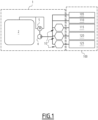
- Figures 1 and 3 illustrate an air supply management system and a method for managing air supply for an equipment comprising a pneumatic system, therein indicated by the overall reference numbers 1 and 200, respectively.
- FIG 1 there is also schematically represented a pneumatic system therein indicated by the overall reference number 100.
- the pneumatic system 100 can comprise or be composed by several parts or subsystems operatively associated to each other.
- Each subsystem or part comprises any suitable number of components, such as pipes or conduits devised to be filled in with pressurized air in order for the subsystem or part to perform the functionalities for which it has been designed for.
- the illustrated pneumatic system 100 is for example the whole pneumatic system of a railway vehicle, in particular of a train, and comprises for instance a main pipe system 105 aimed at distributing pressurized air inside the whole train, a brake system 110 which is suitable to be filled with pressurized air for performing braking functionalities, a suspension system 115 which is suitable to be filled with pressurized air for performing suspension functionalities; further, in figure 1 there is depicted an air reservoir subsystem 120 aimed at storing pressurized air for whatever need and use thereof during the operations of the train, an another optional subsystem 125.
- the air management system 1 comprises:
- the different volumes or capacities of 105, 110, 115, 120, 125 it is also possible to commute between the first and the second states, in order for instance to remain in an acceptable range of pressure in the pneumatic system to allow performing preparation test or first usage.
- This is managed by the controller 2 that is able to monitor the pressure of the pneumatic system 100 thanks to the control means 10 usefully embedding a dedicated sensor for it.
- the controller 2 is configured to start a checking test of at least one of the one or more remaining subsystems or parts filled with pressurized air when the internal pressure of the pneumatic system reaches a predetermined first pressure threshold, and to commute or cause to commute the at least one set of airflow control means 10 from the above indicated first state into the second state, thus allowing pressurized air to flow also into the at least one selected subsystem or part, while carrying out in parallel the checking test.
- At least one set of airflow control means 10 is located at a selected position within the pneumatic system 100 and allows partitioning the whole pneumatic system 100 into parts or subsystems having a higher priority and thus precedence over other lower priority parts or subsystem, in terms of timing for supplying therein pressurized air.
- a selected part or subsystem of the pneumatic system 100 is temporarily isolated impeding the flow of pressurized air into it, while at the same time one or more remaining subsystems or parts of the pneumatic system 100, including the part or subsystem to be tested or used, are filled by the compressor 4 with pressurized air to bring the level of pressure inside such one or more remaining parts or subsystems at a predefined first threshold in the shortest time possible.
- the controller 2 starts the checking test on at least one part or subsystem and, while the test is under execution, the at least one set of control means 10 is commuted into the second state or position, thus allowing flows of pressurized air also into the previously isolated part or subsystem. If necessary, the commutation of the control means 10 can be done either very rapidly or progressively in order to have a smooth transition at the pneumatical system level.
- the actual pressure of the pneumatic system 100 or any part or subsystem thereof can be measured for instance via one or more pressure sensors (not illustrated) which are located at suitable positions within the system 100 itself and which provide the controller 2 with corresponding signals indicative of the actual pressure detected. Further, the control means 10 contain also a pressure sensor in order to monitor the status of filling and if necessary to diagnostic a failure.
- the controller 2 can comprise or be constituted by any processor-based device, e.g. a microprocessor, microcontroller, a microcomputer, a programmable logic controller, an application specific integrated circuit, or any other programmable circuit, commercially available and provided with suitable circuitry to the extent necessary to perform the functionalities provided within the frame of the present invention.
- processor-based device e.g. a microprocessor, microcontroller, a microcomputer, a programmable logic controller, an application specific integrated circuit, or any other programmable circuit, commercially available and provided with suitable circuitry to the extent necessary to perform the functionalities provided within the frame of the present invention.
- the equipment to which the system 1 is used with is a transportation vehicle, such as a train, and whose pneumatic system 100 includes an air brake system 105; accordingly, the controller 2 is adapted to carry out a checking test of the air brake system 105 before the transportation vehicle is put into operation.
- the system 1 comprises a plurality of sets of airflow control means 10, namely two or more sets, each set of airflow control means 10 being associated to a corresponding subsystem or part of the pneumatic system 100,
- FIG. 1 there are used three sets of airflow control means 10, out of which a first set is associated to the suspension subsystem 115, the second set is associated to the air reservoir subsystem 120, and the third set is associated to the optional subsystem 125.
- the controller 2 is configured to commute the sets of airflow control means 10 from the respective first position to the respective second position in a predefined sequence among them.
- the controller 2 first commutes or causes to commute the first set of airflow control means associated to the suspension subsystem 115 from the first state into the second state; thereafter, the controller 2 commutes or causes to commute the second set of airflow control means 10 associated to the air reservoir subsystem 120 from the respective first state into the respective second state; finally, the controller 2 commutes or causes the third set of airflow control means 10 associated to the subsystem 125 to commute from the respective first state into the respective second state.
- the controller 2 is configured to commute at least two sets of airflow control means 10, or even all sets used, from the respective first state to the respective second state in parallel, e.g. substantially at the same time, to each other.
- the time when the controller 2 commutes or causes to commute the or each set of airflow control means 10 used can be properly selected and suitably programmed.
- the commutation from the fist state to the second state can be started substantially simultaneously with the starting of the checking test.
- the commutation from the first position to the second position can be carried out, while the checking test is under execution, when the pressure inside the pneumatic system 100 reaches a second pressure threshold, which can be different, for example a certain amount higher than the previously mentioned pressure threshold at which the checking test is started.
- the second set can be triggered for example when, after starting to fill in with pressurized air the first previously isolated subsystem, the pressure level inside the whole pneumatic system 100 reaches a second pressure threshold; the second pressure threshold can be different, for example a certain amount higher than the previously mentioned first pressure threshold at which the checking test is started.
- each subsequent set can be commuted or caused to commute when the pressure level inside the whole pneumatic system 100, including the subsystems or parts already supplied with pressurized air, reaches again the second pressure threshold, or any other suitable value.
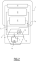
- the or each set of airflow control means 10 comprises a few and quite standard components.
- the or each set of airflow control means 10 comprises at least one valve 12 configured to temporary fluidly isolate the at least one selected subsystem or part 115, 120, or 125 of the pneumatic system 100 to which the corresponding set is associated with.
- the at least one valve 12 comprises an electro valve which can commute or be actuated to commute from the first state (or first position) into the second state (or second position), for example by a control signal S c outputted by a command module 20 of the controller 2 when the pressure inside the pneumatic system 100 reaches the predetermined first pressure threshold, or a different pressure threshold purposively selected for it, such as the above mentioned second pressure threshold.
- the at least one valve 12 comprises a minimum pressure valve.
- the minimum pressure valve is adapted to remain in said first state until when the pressure inside the pneumatic system 100 does not reach said predetermined first pressure threshold or a different pressure threshold purposively selected for it, such as the above mentioned second pressure threshold, at which it can commute or caused to commute, for example by a control signal S c outputted by the controller 2.
- the or each set of airflow control means 10 further comprises at least one sensor 14 for monitoring the correct functioning of the at least one valve 12.
- the or each set of airflow control means 10 further comprises at least one bypass device 16 for bypassing the at least one valve 12 if the at least one sensor 14 detects a failure or malfunctioning of the monitored at least one valve 12.
- Such bypass device 16 can be for example a valve, a cock or any equivalent device configured to allow the flow of pressurized air if actuated to permit so.
- the senor 14 monitors the associated valve 12 and provides corresponding monitoring signals S M to the controller 2. If, by analyzing the signals received from the sensor 14, a monitoring module 22 of the controller 12 identifies that the valve 12 is not working properly for whatever reason, then the controller will alert an operator to actuate the bypass device 16, or it will actuate the bypass device 16 via an actuation signal S A emitted for example by a control module 24.
- the controller 2 shall then receive a feedback signal that the bypass device 16 is effective, for instance through a dedicated contact on the bypass signal.
- a method 200 for managing air supply for an equipment comprising a pneumatic system 100, at least one part or subsystem of which has to undergo a checking test before putting the equipment into operations is illustrated in figure 3 .
- the method 200 which can be carried out in connection with the system 1 or any part thereof, comprises at least the following phases:
- the phase 230 of starting a checking test comprises verifying the functioning of the air brake system 115.
- the method 200 according to the invention can carry out all functionalities described above in connection with the air supply management system 1, and which are not described hereinafter in terms of method phases, sub-phases or steps, just for the sake of conciseness.
- steps 230 and 240 can be executed in parallel, allowing time saving for the readiness of the pneumatic system, and in particular of the vehicle of the above illustrated example.
- the air supply management system 1 and method 200 according to the present invention allow reducing substantially the time needed for filling with pressurized air a pneumatic system and conducting a check test on the pneumatic system or part thereof before putting the equipment into operations.
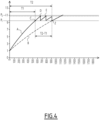
- the compressor 2 fills first the subsystem 105 and 110 with pressurized air.
- the predetermined first pressure threshold P 1 e.g. a relative pressure of 8,5 bars
- the test of the air brake system 110 is started.
- the first set of airflow control means 10 associated to the subsystem 110 commute or is caused to commute, and the subsystem 110 becomes to be supplied with pressurized air (point D).
- point D pressurized air
- test is started (point Z along dotted curve B) only after the whole pressure system and related subsystems are filled at the same time with pressurized air and the pressure of the whole pneumatic system including all its subsystems reaches the first pressure threshold, i.e. after a longer time interval T2.
- T2-T1 a reduction of time needed is achieved (T2-T1), which in the example of figure 4 is about 40%.
- the present invention encompasses also:
- the present invention encompasses a transportation vehicle, in particular a railway vehicle, notably a train, characterized in that it comprises an air supply management system 1 or a pneumatic system 100 as above described, and in particular as defined in one or more of the relevant appended claims.
- system 1 and method 200 thus conceived are susceptible of modifications and variations, all of which are within the scope of the inventive concept as defined in particular by the appended claims; for example, one or more of the sets of airflow control means can be provided with different components or with components additional to those previously described, provided that such airflow control means remain suitable for the scope and functionalities they are conceived for within the frame of the present invention. All the details may furthermore be replaced with technically equivalent elements.
Landscapes
- Engineering & Computer Science (AREA)
- Transportation (AREA)
- Mechanical Engineering (AREA)
- Valves And Accessory Devices For Braking Systems (AREA)
Claims (15)
- Luftzufuhr-Managementsystem (1) für eine Ausrüstung, umfassend ein pneumatisches System (100), wovon mindestens ein Teil oder ein Teilsystem (110) vor Inbetriebnahme der Ausrüstung einer Kontrollprüfung unterzogen werden muss, das Luftmanagementsystem (1) mindestens umfassend:- eine Steuerung (2);- einen Kompressor (4), der konfiguriert ist, um dem pneumatischen System (100) Druckluft zuzuführen; gekennzeichnet durch- mindestens einen Satz von Luftstrom-Steuereinrichtungen (10), die mit dem pneumatischen System (100) verbunden und konfiguriert sind, um zwischen einem ersten Zustand, in dem sie ein Einströmen von Druckluft in mindestens ein ausgewähltes Teilsystem oder Teil (105, 110, 115, 120, 125) des pneumatischen Systems (100) verhindern, während ein oder mehrere verbleibende Teilsysteme oder Teile (105, 110, 115, 120, 125) des pneumatischen Systems (100) mit Druckluft gefüllt sind, und einem zweiten Zustand, in dem eine Strömung von Druckluft in das mindestens eine ausgewählte Teilsystem oder Teil (105, 110) zugelassen ist, umzuschalten;wobei die Steuerung (2) konfiguriert ist, um eine Kontrollprüfung von mindestens einem von dem einen oder den mehreren restlichen Teilsystemen oder Teilen (105, 110), die mit Druckluft gefüllt sind, zu beginnen, wenn der Innendruck des pneumatischen Systems (100) einen vorbestimmten Schwellenwert erreicht, und um den mindestens einen Satz von Luftstrom-Steuereinrichtungen (10) von der ersten Position in die zweite Position umzuschalten oder dies zu bewirken, sodass Druckluft in das mindestens eine ausgewählte Teilsystem oder Teil (105, 110, 115, 120, 125) strömen kann, während gleichzeitig die Kontrollprüfung durchgeführt wird.
- Luftzufuhr-Managementsystem (1) nach Anspruch 1, wobei der mindestens einen Satz von Luftstrom-Steuereinrichtungen (10) mindestens ein Ventil (12) umfasst, das konfiguriert ist, um das mindestens eine ausgewählte Teilsystem oder Teil (115, 120, 125) des pneumatischen Systems (100) vorübergehend fluidisch zu isolieren.
- Luftzufuhrmanagementsystem (1) nach Anspruch 2, wobei der mindestens einen Satz von Luftstrom-Steuereinrichtungen (10) ferner mindestens einen Sensor (14) zum Überwachen des mindestens einen Ventils (12) umfasst.
- Luftzufuhr-Managementsystem (1) nach Anspruch 3, wobei der mindestens einen Satz von Luftstrom-Steuereinrichtungen (10) ferner mindestens eine Bypass-Vorrichtung (16) zum Umgehen des mindestens einen Ventils (12) umfasst, wenn der mindestens eine Sensor (14) einen Ausfall des überwachten mindestens einen Ventils (12) erkennt.
- Luftzufuhr-Managementsystem (1) nach Anspruch 2, wobei das mindestens ein Ventil (12) ein Elektroventil umfasst.
- Luftzufuhr-Managementsystem (1) nach Anspruch 2, wobei das mindestens ein Ventil (12) ein Mindestdruckventil umfasst.
- Luftzufuhr-Managementsystem (1) nach einem der vorherigen Ansprüche, wobei es eine Vielzahl von Sätzen von Luftstrom-Steuereinrichtungen (10) umfasst, wobei jeder Satz von Luftstrom-Steuereinrichtungen (10) mit einem entsprechenden Teilsystem oder Teil des pneumatischen Systems (100) assoziiert ist, und wobei die Steuerung (2) konfiguriert ist, um die Sätze von Luftstrom-Steuereinrichtungen (10) in einer vordefinierten Reihenfolge von der jeweiligen ersten Position in die jeweilige zweite Position umzuschalten oder dies zu bewirken.
- Luftzufuhr-Managementsystem (1) nach einem der Ansprüche 1 bis 6, wobei es eine Vielzahl von Sätzen von Luftstrom-Steuereinrichtungen (10) umfasst, wobei jeder Satz von Luftstrom-Steuereinrichtungen (10) mit einem entsprechenden Teilsystem oder Teil des pneumatischen Systems (100) assoziiert ist, und wobei die Steuerung (2) konfiguriert ist, um mindestens zwei Sätze von Luftstrom-Steuereinrichtungen (10) parallel zueinander von der jeweiligen ersten Position in die jeweilige zweite Position umzuschalten oder dies zu bewirken.
- Luftzufuhr-Managementsystem (1) nach einem der vorherigen Ansprüche, wobei die Ausrüstung ein Transportfahrzeug ist, umfassend das pneumatische System (100), und wobei eines von dem Teilsystem oder Teil ein Luftbremssystem (105) ist, und wobei die Steuerung (2) angepasst ist, um einen Bremstest des Luftbremssystems (105) durchzuführen, bevor das Transportfahrzeug in Betrieb genommen wird.
- Pneumatisches System (100) einer Ausrüstung, dadurch gekennzeichnet, dass es ein Luftzufuhr-Managementsystem (1) nach einem der vorherigen Ansprüche umfasst.
- Ausrüstung, dadurch gekennzeichnet, dass sie ein Luftzufuhr-Managementsystem (1) nach einem der Ansprüche 1 bis 9 oder ein pneumatisches System (100) nach Anspruch 10 umfasst.
- Transportfahrzeug, dadurch gekennzeichnet, dass es ein Luftzufuhr-Managementsystem (1) nach einem der Ansprüche 1 bis 9 oder ein pneumatisches System (100) nach Anspruch 10 umfasst.
- Transportfahrzeug nach Anspruch 12, wobei das Transportfahrzeug ein Schienenfahrzeug ist.
- Verfahren (200) zum Managen der Luftzufuhr für eine Ausrüstung, umfassend ein pneumatisches System (100), wovon mindestens ein Teil oder ein Teilsystem vor der Inbetriebnahme der Ausrüstung einer Kontrollprüfung unterzogen werden muss, wobei das Verfahren (200) dadurch gekennzeichnet, dass es mindestens die folgenden Phasen umfasst:- (210): Versehen des pneumatischen Systems (100) mit mindestens einem Satz von Luftstrom-Steuereinrichtungen (10), die konfiguriert sind, um zwischen einem ersten Zustand, in dem sie vorübergehend verhindern, dass Druckluft in mindestens ein ausgewähltes Teilsystem oder Teil (105, 110, 115, 120, 125) des pneumatischen Systems (100) strömt, und einem zweiten Zustand, in dem eine Strömung von Druckluft in das mindestens eine ausgewählte Teilsystem oder Teil (105, 110, 115, 120, 125) zugelassen ist, umzuschalten;- (220): Zuführen von Druckluft zu einem oder mehreren restlichen Teilsystemen oder Teilen (105, 110, 115, 120, 125) des pneumatischen Systems (100), während der mindestens einen Satz von Luftstrom-Steuereinrichtungen (10) in dem ersten Zustand gehalten wird, um vorübergehend zu verhindern, dass Druckluft in das mindestens eine ausgewählte Teilsystem oder Teil (105, 110, 115, 120, 125) des pneumatischen Systems (100) strömt;- (230): Beginnen einer Kontrollprüfung von mindestens einem der restlichen Teilsysteme oder Teile (105, 110, 115, 120, 125), die mit Druckluft gefüllt sind, wenn der Innendruck des pneumatischen Systems (100) einen vorbestimmten ersten Druckschwellenwert erreicht,- (240): Umschalten des mindestens eines Satzes von Luftstrom-Steuereinrichtungen (10) von der ersten Position in die zweite Position oder dies bewirken, um zu ermöglichen, dass Druckluft in das mindestens eine ausgewählte Teilsystem oder Teil (105, 110, 115, 120, 125) strömt, während parallel dazu die Kontrollprüfung durchgeführt wird.
- Verfahren (200) nach Anspruch 14, wobei die Ausrüstung ein Transportfahrzeug ist, dessen pneumatisches System (100) mindestens ein Druckluftbremssystem (110) umfasst, und wobei die Phase (230) eines Beginnens einer Kontrollprüfung ein Beginnen einer Bremsprüfung umfasst, um das Funktionieren des Druckluftbremssystems (110) zu überprüfen.
Priority Applications (1)
| Application Number | Priority Date | Filing Date | Title |
|---|---|---|---|
| EP21306596.4A EP4183646B1 (de) | 2021-11-17 | 2021-11-17 | Luftversorgungverwaltungssystem und -verfahren für eine ausrüstung mit einem pneumatischen system und zugehöriges pneumatisches system und ausrüstung, insbesondere ein transportfahrzeug |
Applications Claiming Priority (1)
| Application Number | Priority Date | Filing Date | Title |
|---|---|---|---|
| EP21306596.4A EP4183646B1 (de) | 2021-11-17 | 2021-11-17 | Luftversorgungverwaltungssystem und -verfahren für eine ausrüstung mit einem pneumatischen system und zugehöriges pneumatisches system und ausrüstung, insbesondere ein transportfahrzeug |
Publications (2)
| Publication Number | Publication Date |
|---|---|
| EP4183646A1 EP4183646A1 (de) | 2023-05-24 |
| EP4183646B1 true EP4183646B1 (de) | 2024-09-04 |
Family
ID=78819988
Family Applications (1)
| Application Number | Title | Priority Date | Filing Date |
|---|---|---|---|
| EP21306596.4A Active EP4183646B1 (de) | 2021-11-17 | 2021-11-17 | Luftversorgungverwaltungssystem und -verfahren für eine ausrüstung mit einem pneumatischen system und zugehöriges pneumatisches system und ausrüstung, insbesondere ein transportfahrzeug |
Country Status (1)
| Country | Link |
|---|---|
| EP (1) | EP4183646B1 (de) |
Family Cites Families (4)
| Publication number | Priority date | Publication date | Assignee | Title |
|---|---|---|---|---|
| US6401015B1 (en) * | 1997-10-14 | 2002-06-04 | Scot Stewart | Distributed power and electronic air brake control system for a train and associated methods |
| DK2371640T3 (da) * | 2010-03-26 | 2014-10-20 | Kombimatic As | Indretning til afprøvning af et køretøjs bremser og fremgangsmåde til afprøvning af et køretøjs bremser |
| EP3552894B1 (de) * | 2016-12-08 | 2023-02-08 | Nabtesco Automotive Corporation | Luftzufuhrsystem |
| US11858491B2 (en) * | 2018-10-30 | 2024-01-02 | Outrider Technologies, Inc. | System and method for controlling braking functions in an autonomous vehicle |
-
2021
- 2021-11-17 EP EP21306596.4A patent/EP4183646B1/de active Active
Also Published As
| Publication number | Publication date |
|---|---|
| EP4183646A1 (de) | 2023-05-24 |
Similar Documents
| Publication | Publication Date | Title |
|---|---|---|
| CN111656206A (zh) | 用于监控具有自动化行驶功能的机动车的能量供给的方法 | |
| CN103253273B (zh) | 车辆的安全运行 | |
| JP2010523384A (ja) | 非常釈放機能を持つ車両の駐車制動装置及びこのような駐車制動装置の操作方法 | |
| KR20150028814A (ko) | 레일 차량의, 브레이크 압력을 안내하는 브레이크 압력 라인 내의 누설 검출 방법 | |
| KR20140005557A (ko) | 에어 컴프레서의 에러 검출 방법 | |
| CN112298151B (zh) | 一种动车组停放制动状态监控方法、装置、系统和动车组 | |
| US20130047705A1 (en) | System and method for testing a rail car brake system | |
| US12036964B2 (en) | Brake health monitoring system | |
| CN109383472B (zh) | 轨道车辆用空压机控制方法及系统 | |
| MX2010011860A (es) | Sistema de frenado. | |
| EP4183646B1 (de) | Luftversorgungverwaltungssystem und -verfahren für eine ausrüstung mit einem pneumatischen system und zugehöriges pneumatisches system und ausrüstung, insbesondere ein transportfahrzeug | |
| KR102808230B1 (ko) | 차량, 특히 철도 차량의 공기 공급 시스템의 파라미터를 모니터링하고 측정하기 위한 모니터링- 및 측정 장치와 방법 | |
| US20170240157A1 (en) | Compressed-air brake assembly for a rail vehicle | |
| CA2720540C (en) | Ecp terminal mode operation | |
| KR101240134B1 (ko) | 전자식 차량 브레이크 시스템의 블리딩 방법 | |
| CN107074225A (zh) | 用于铁路制动系统的自测方法 | |
| BR112014027895B1 (pt) | Disposição de retorno do dispositivo vazio de carga para um trem com pelo menos um transporte ferroviário tendo uma disposição de freio pneumático com pelo menos um conjunto de frenagem operável por ar, e disposição de freio pneumático | |
| CN110386165B (zh) | 一种集成气路装置及其气路控制方法、列车 | |
| AU2021315565B2 (en) | Excessive train brake pipe flow diagnostics | |
| CZ2018459A3 (cs) | Způsob provedení automatické zkoušky brzd kolejového vozidla nebo soupravy | |
| US10086849B2 (en) | Vehicle, in particular rail vehicle, with a compressed air-operated toilet device | |
| CN102248939A (zh) | 一种用于防抱死制动系统的故障显示控制系统及其方法 | |
| US20200207314A1 (en) | Vehicle fluid fill system | |
| RU85133U1 (ru) | Устройство возимой диагностики автотормозов на электро- и дизельпоездах | |
| CN117400897A (zh) | 铁路货车制动管系泄漏故障监测方法、装置及电子设备 |
Legal Events
| Date | Code | Title | Description |
|---|---|---|---|
| PUAI | Public reference made under article 153(3) epc to a published international application that has entered the european phase |
Free format text: ORIGINAL CODE: 0009012 |
|
| STAA | Information on the status of an ep patent application or granted ep patent |
Free format text: STATUS: THE APPLICATION HAS BEEN PUBLISHED |
|
| AK | Designated contracting states |
Kind code of ref document: A1 Designated state(s): AL AT BE BG CH CY CZ DE DK EE ES FI FR GB GR HR HU IE IS IT LI LT LU LV MC MK MT NL NO PL PT RO RS SE SI SK SM TR |
|
| STAA | Information on the status of an ep patent application or granted ep patent |
Free format text: STATUS: REQUEST FOR EXAMINATION WAS MADE |
|
| 17P | Request for examination filed |
Effective date: 20230531 |
|
| RBV | Designated contracting states (corrected) |
Designated state(s): AL AT BE BG CH CY CZ DE DK EE ES FI FR GB GR HR HU IE IS IT LI LT LU LV MC MK MT NL NO PL PT RO RS SE SI SK SM TR |
|
| P01 | Opt-out of the competence of the unified patent court (upc) registered |
Effective date: 20230823 |
|
| RAP1 | Party data changed (applicant data changed or rights of an application transferred) |
Owner name: ALSTOM HOLDINGS |
|
| GRAP | Despatch of communication of intention to grant a patent |
Free format text: ORIGINAL CODE: EPIDOSNIGR1 |
|
| STAA | Information on the status of an ep patent application or granted ep patent |
Free format text: STATUS: GRANT OF PATENT IS INTENDED |
|
| INTG | Intention to grant announced |
Effective date: 20240422 |
|
| GRAS | Grant fee paid |
Free format text: ORIGINAL CODE: EPIDOSNIGR3 |
|
| GRAA | (expected) grant |
Free format text: ORIGINAL CODE: 0009210 |
|
| STAA | Information on the status of an ep patent application or granted ep patent |
Free format text: STATUS: THE PATENT HAS BEEN GRANTED |
|
| AK | Designated contracting states |
Kind code of ref document: B1 Designated state(s): AL AT BE BG CH CY CZ DE DK EE ES FI FR GB GR HR HU IE IS IT LI LT LU LV MC MK MT NL NO PL PT RO RS SE SI SK SM TR |
|
| REG | Reference to a national code |
Ref country code: GB Ref legal event code: FG4D |
|
| REG | Reference to a national code |
Ref country code: CH Ref legal event code: EP |
|
| REG | Reference to a national code |
Ref country code: IE Ref legal event code: FG4D |
|
| REG | Reference to a national code |
Ref country code: DE Ref legal event code: R096 Ref document number: 602021018267 Country of ref document: DE |
|
| REG | Reference to a national code |
Ref country code: LT Ref legal event code: MG9D |
|
| REG | Reference to a national code |
Ref country code: NL Ref legal event code: MP Effective date: 20240904 |
|
| PGFP | Annual fee paid to national office [announced via postgrant information from national office to epo] |
Ref country code: DE Payment date: 20241129 Year of fee payment: 4 |
|
| PG25 | Lapsed in a contracting state [announced via postgrant information from national office to epo] |
Ref country code: NO Free format text: LAPSE BECAUSE OF FAILURE TO SUBMIT A TRANSLATION OF THE DESCRIPTION OR TO PAY THE FEE WITHIN THE PRESCRIBED TIME-LIMIT Effective date: 20241204 |
|
| PG25 | Lapsed in a contracting state [announced via postgrant information from national office to epo] |
Ref country code: PL Free format text: LAPSE BECAUSE OF FAILURE TO SUBMIT A TRANSLATION OF THE DESCRIPTION OR TO PAY THE FEE WITHIN THE PRESCRIBED TIME-LIMIT Effective date: 20240904 Ref country code: GR Free format text: LAPSE BECAUSE OF FAILURE TO SUBMIT A TRANSLATION OF THE DESCRIPTION OR TO PAY THE FEE WITHIN THE PRESCRIBED TIME-LIMIT Effective date: 20241205 Ref country code: FI Free format text: LAPSE BECAUSE OF FAILURE TO SUBMIT A TRANSLATION OF THE DESCRIPTION OR TO PAY THE FEE WITHIN THE PRESCRIBED TIME-LIMIT Effective date: 20240904 |
|
| PG25 | Lapsed in a contracting state [announced via postgrant information from national office to epo] |
Ref country code: BG Free format text: LAPSE BECAUSE OF FAILURE TO SUBMIT A TRANSLATION OF THE DESCRIPTION OR TO PAY THE FEE WITHIN THE PRESCRIBED TIME-LIMIT Effective date: 20240904 |
|
| PGFP | Annual fee paid to national office [announced via postgrant information from national office to epo] |
Ref country code: FR Payment date: 20241129 Year of fee payment: 4 |
|
| PG25 | Lapsed in a contracting state [announced via postgrant information from national office to epo] |
Ref country code: LV Free format text: LAPSE BECAUSE OF FAILURE TO SUBMIT A TRANSLATION OF THE DESCRIPTION OR TO PAY THE FEE WITHIN THE PRESCRIBED TIME-LIMIT Effective date: 20240904 |
|
| PG25 | Lapsed in a contracting state [announced via postgrant information from national office to epo] |
Ref country code: HR Free format text: LAPSE BECAUSE OF FAILURE TO SUBMIT A TRANSLATION OF THE DESCRIPTION OR TO PAY THE FEE WITHIN THE PRESCRIBED TIME-LIMIT Effective date: 20240904 |
|
| PG25 | Lapsed in a contracting state [announced via postgrant information from national office to epo] |
Ref country code: ES Free format text: LAPSE BECAUSE OF FAILURE TO SUBMIT A TRANSLATION OF THE DESCRIPTION OR TO PAY THE FEE WITHIN THE PRESCRIBED TIME-LIMIT Effective date: 20240904 Ref country code: RS Free format text: LAPSE BECAUSE OF FAILURE TO SUBMIT A TRANSLATION OF THE DESCRIPTION OR TO PAY THE FEE WITHIN THE PRESCRIBED TIME-LIMIT Effective date: 20241204 |
|
| PGFP | Annual fee paid to national office [announced via postgrant information from national office to epo] |
Ref country code: IT Payment date: 20241130 Year of fee payment: 4 |
|
| PG25 | Lapsed in a contracting state [announced via postgrant information from national office to epo] |
Ref country code: RS Free format text: LAPSE BECAUSE OF FAILURE TO SUBMIT A TRANSLATION OF THE DESCRIPTION OR TO PAY THE FEE WITHIN THE PRESCRIBED TIME-LIMIT Effective date: 20241204 Ref country code: PL Free format text: LAPSE BECAUSE OF FAILURE TO SUBMIT A TRANSLATION OF THE DESCRIPTION OR TO PAY THE FEE WITHIN THE PRESCRIBED TIME-LIMIT Effective date: 20240904 Ref country code: NO Free format text: LAPSE BECAUSE OF FAILURE TO SUBMIT A TRANSLATION OF THE DESCRIPTION OR TO PAY THE FEE WITHIN THE PRESCRIBED TIME-LIMIT Effective date: 20241204 Ref country code: LV Free format text: LAPSE BECAUSE OF FAILURE TO SUBMIT A TRANSLATION OF THE DESCRIPTION OR TO PAY THE FEE WITHIN THE PRESCRIBED TIME-LIMIT Effective date: 20240904 Ref country code: HR Free format text: LAPSE BECAUSE OF FAILURE TO SUBMIT A TRANSLATION OF THE DESCRIPTION OR TO PAY THE FEE WITHIN THE PRESCRIBED TIME-LIMIT Effective date: 20240904 Ref country code: GR Free format text: LAPSE BECAUSE OF FAILURE TO SUBMIT A TRANSLATION OF THE DESCRIPTION OR TO PAY THE FEE WITHIN THE PRESCRIBED TIME-LIMIT Effective date: 20241205 Ref country code: FI Free format text: LAPSE BECAUSE OF FAILURE TO SUBMIT A TRANSLATION OF THE DESCRIPTION OR TO PAY THE FEE WITHIN THE PRESCRIBED TIME-LIMIT Effective date: 20240904 Ref country code: ES Free format text: LAPSE BECAUSE OF FAILURE TO SUBMIT A TRANSLATION OF THE DESCRIPTION OR TO PAY THE FEE WITHIN THE PRESCRIBED TIME-LIMIT Effective date: 20240904 Ref country code: BG Free format text: LAPSE BECAUSE OF FAILURE TO SUBMIT A TRANSLATION OF THE DESCRIPTION OR TO PAY THE FEE WITHIN THE PRESCRIBED TIME-LIMIT Effective date: 20240904 |
|
| REG | Reference to a national code |
Ref country code: AT Ref legal event code: MK05 Ref document number: 1720074 Country of ref document: AT Kind code of ref document: T Effective date: 20240904 |
|
| PG25 | Lapsed in a contracting state [announced via postgrant information from national office to epo] |
Ref country code: NL Free format text: LAPSE BECAUSE OF FAILURE TO SUBMIT A TRANSLATION OF THE DESCRIPTION OR TO PAY THE FEE WITHIN THE PRESCRIBED TIME-LIMIT Effective date: 20240904 |
|
| PG25 | Lapsed in a contracting state [announced via postgrant information from national office to epo] |
Ref country code: IS Free format text: LAPSE BECAUSE OF FAILURE TO SUBMIT A TRANSLATION OF THE DESCRIPTION OR TO PAY THE FEE WITHIN THE PRESCRIBED TIME-LIMIT Effective date: 20250104 Ref country code: PT Free format text: LAPSE BECAUSE OF FAILURE TO SUBMIT A TRANSLATION OF THE DESCRIPTION OR TO PAY THE FEE WITHIN THE PRESCRIBED TIME-LIMIT Effective date: 20250106 |
|
| PG25 | Lapsed in a contracting state [announced via postgrant information from national office to epo] |
Ref country code: RO Free format text: LAPSE BECAUSE OF FAILURE TO SUBMIT A TRANSLATION OF THE DESCRIPTION OR TO PAY THE FEE WITHIN THE PRESCRIBED TIME-LIMIT Effective date: 20240904 Ref country code: SM Free format text: LAPSE BECAUSE OF FAILURE TO SUBMIT A TRANSLATION OF THE DESCRIPTION OR TO PAY THE FEE WITHIN THE PRESCRIBED TIME-LIMIT Effective date: 20240904 |
|
| PG25 | Lapsed in a contracting state [announced via postgrant information from national office to epo] |
Ref country code: EE Free format text: LAPSE BECAUSE OF FAILURE TO SUBMIT A TRANSLATION OF THE DESCRIPTION OR TO PAY THE FEE WITHIN THE PRESCRIBED TIME-LIMIT Effective date: 20240904 Ref country code: AT Free format text: LAPSE BECAUSE OF FAILURE TO SUBMIT A TRANSLATION OF THE DESCRIPTION OR TO PAY THE FEE WITHIN THE PRESCRIBED TIME-LIMIT Effective date: 20240904 |
|
| PG25 | Lapsed in a contracting state [announced via postgrant information from national office to epo] |
Ref country code: CZ Free format text: LAPSE BECAUSE OF FAILURE TO SUBMIT A TRANSLATION OF THE DESCRIPTION OR TO PAY THE FEE WITHIN THE PRESCRIBED TIME-LIMIT Effective date: 20240904 |
|
| PG25 | Lapsed in a contracting state [announced via postgrant information from national office to epo] |
Ref country code: SK Free format text: LAPSE BECAUSE OF FAILURE TO SUBMIT A TRANSLATION OF THE DESCRIPTION OR TO PAY THE FEE WITHIN THE PRESCRIBED TIME-LIMIT Effective date: 20240904 |
|
| REG | Reference to a national code |
Ref country code: DE Ref legal event code: R097 Ref document number: 602021018267 Country of ref document: DE |
|
| REG | Reference to a national code |
Ref country code: CH Ref legal event code: PL |
|
| PG25 | Lapsed in a contracting state [announced via postgrant information from national office to epo] |
Ref country code: MC Free format text: LAPSE BECAUSE OF FAILURE TO SUBMIT A TRANSLATION OF THE DESCRIPTION OR TO PAY THE FEE WITHIN THE PRESCRIBED TIME-LIMIT Effective date: 20240904 |
|
| PG25 | Lapsed in a contracting state [announced via postgrant information from national office to epo] |
Ref country code: DK Free format text: LAPSE BECAUSE OF FAILURE TO SUBMIT A TRANSLATION OF THE DESCRIPTION OR TO PAY THE FEE WITHIN THE PRESCRIBED TIME-LIMIT Effective date: 20240904 |
|
| PLBE | No opposition filed within time limit |
Free format text: ORIGINAL CODE: 0009261 |
|
| STAA | Information on the status of an ep patent application or granted ep patent |
Free format text: STATUS: NO OPPOSITION FILED WITHIN TIME LIMIT |
|
| PG25 | Lapsed in a contracting state [announced via postgrant information from national office to epo] |
Ref country code: LU Free format text: LAPSE BECAUSE OF NON-PAYMENT OF DUE FEES Effective date: 20241117 |
|
| REG | Reference to a national code |
Ref country code: CH Ref legal event code: PL |
|
| PG25 | Lapsed in a contracting state [announced via postgrant information from national office to epo] |
Ref country code: CH Free format text: LAPSE BECAUSE OF NON-PAYMENT OF DUE FEES Effective date: 20241130 |
|
| 26N | No opposition filed |
Effective date: 20250605 |
|
| REG | Reference to a national code |
Ref country code: BE Ref legal event code: MM Effective date: 20241130 |
|
| PG25 | Lapsed in a contracting state [announced via postgrant information from national office to epo] |
Ref country code: SE Free format text: LAPSE BECAUSE OF FAILURE TO SUBMIT A TRANSLATION OF THE DESCRIPTION OR TO PAY THE FEE WITHIN THE PRESCRIBED TIME-LIMIT Effective date: 20240904 |
|
| PG25 | Lapsed in a contracting state [announced via postgrant information from national office to epo] |
Ref country code: BE Free format text: LAPSE BECAUSE OF NON-PAYMENT OF DUE FEES Effective date: 20241130 |
|
| PG25 | Lapsed in a contracting state [announced via postgrant information from national office to epo] |
Ref country code: IE Free format text: LAPSE BECAUSE OF NON-PAYMENT OF DUE FEES Effective date: 20241117 |