EP4183638A1 - Dispositif de protection d'occupant - Google Patents
Dispositif de protection d'occupant Download PDFInfo
- Publication number
- EP4183638A1 EP4183638A1 EP21842425.7A EP21842425A EP4183638A1 EP 4183638 A1 EP4183638 A1 EP 4183638A1 EP 21842425 A EP21842425 A EP 21842425A EP 4183638 A1 EP4183638 A1 EP 4183638A1
- Authority
- EP
- European Patent Office
- Prior art keywords
- mounting point
- vehicle seat
- lower panel
- upper panel
- point
- Prior art date
- Legal status (The legal status is an assumption and is not a legal conclusion. Google has not performed a legal analysis and makes no representation as to the accuracy of the status listed.)
- Pending
Links
Images


Classifications
-
- B—PERFORMING OPERATIONS; TRANSPORTING
- B60—VEHICLES IN GENERAL
- B60N—SEATS SPECIALLY ADAPTED FOR VEHICLES; VEHICLE PASSENGER ACCOMMODATION NOT OTHERWISE PROVIDED FOR
- B60N2/00—Seats specially adapted for vehicles; Arrangement or mounting of seats in vehicles
- B60N2/24—Seats specially adapted for vehicles; Arrangement or mounting of seats in vehicles for particular purposes or particular vehicles
- B60N2/42—Seats specially adapted for vehicles; Arrangement or mounting of seats in vehicles for particular purposes or particular vehicles the seat constructed to protect the occupant from the effect of abnormal g-forces, e.g. crash or safety seats
- B60N2/427—Seats or parts thereof displaced during a crash
- B60N2/42727—Seats or parts thereof displaced during a crash involving substantially rigid displacement
- B60N2/42754—Seats or parts thereof displaced during a crash involving substantially rigid displacement of the cushion
- B60N2/42763—Seats or parts thereof displaced during a crash involving substantially rigid displacement of the cushion with anti-submarining systems
-
- B—PERFORMING OPERATIONS; TRANSPORTING
- B60—VEHICLES IN GENERAL
- B60N—SEATS SPECIALLY ADAPTED FOR VEHICLES; VEHICLE PASSENGER ACCOMMODATION NOT OTHERWISE PROVIDED FOR
- B60N2/00—Seats specially adapted for vehicles; Arrangement or mounting of seats in vehicles
- B60N2/24—Seats specially adapted for vehicles; Arrangement or mounting of seats in vehicles for particular purposes or particular vehicles
- B60N2/42—Seats specially adapted for vehicles; Arrangement or mounting of seats in vehicles for particular purposes or particular vehicles the seat constructed to protect the occupant from the effect of abnormal g-forces, e.g. crash or safety seats
- B60N2/427—Seats or parts thereof displaced during a crash
- B60N2/42772—Seats or parts thereof displaced during a crash characterised by the triggering system
- B60N2/4279—Seats or parts thereof displaced during a crash characterised by the triggering system electric or electronic triggering
-
- B—PERFORMING OPERATIONS; TRANSPORTING
- B60—VEHICLES IN GENERAL
- B60R—VEHICLES, VEHICLE FITTINGS, OR VEHICLE PARTS, NOT OTHERWISE PROVIDED FOR
- B60R21/00—Arrangements or fittings on vehicles for protecting or preventing injuries to occupants or pedestrians in case of accidents or other traffic risks
- B60R21/02—Occupant safety arrangements or fittings, e.g. crash pads
- B60R21/16—Inflatable occupant restraints or confinements designed to inflate upon impact or impending impact, e.g. air bags
- B60R21/20—Arrangements for storing inflatable members in their non-use or deflated condition; Arrangement or mounting of air bag modules or components
- B60R21/207—Arrangements for storing inflatable members in their non-use or deflated condition; Arrangement or mounting of air bag modules or components in vehicle seats
-
- B—PERFORMING OPERATIONS; TRANSPORTING
- B60—VEHICLES IN GENERAL
- B60R—VEHICLES, VEHICLE FITTINGS, OR VEHICLE PARTS, NOT OTHERWISE PROVIDED FOR
- B60R21/00—Arrangements or fittings on vehicles for protecting or preventing injuries to occupants or pedestrians in case of accidents or other traffic risks
- B60R21/02—Occupant safety arrangements or fittings, e.g. crash pads
- B60R21/16—Inflatable occupant restraints or confinements designed to inflate upon impact or impending impact, e.g. air bags
- B60R21/26—Inflatable occupant restraints or confinements designed to inflate upon impact or impending impact, e.g. air bags characterised by the inflation fluid source or means to control inflation fluid flow
- B60R21/264—Inflatable occupant restraints or confinements designed to inflate upon impact or impending impact, e.g. air bags characterised by the inflation fluid source or means to control inflation fluid flow using instantaneous generation of gas, e.g. pyrotechnic
-
- B—PERFORMING OPERATIONS; TRANSPORTING
- B60—VEHICLES IN GENERAL
- B60R—VEHICLES, VEHICLE FITTINGS, OR VEHICLE PARTS, NOT OTHERWISE PROVIDED FOR
- B60R21/00—Arrangements or fittings on vehicles for protecting or preventing injuries to occupants or pedestrians in case of accidents or other traffic risks
- B60R21/02—Occupant safety arrangements or fittings, e.g. crash pads
- B60R21/16—Inflatable occupant restraints or confinements designed to inflate upon impact or impending impact, e.g. air bags
- B60R21/20—Arrangements for storing inflatable members in their non-use or deflated condition; Arrangement or mounting of air bag modules or components
- B60R21/215—Arrangements for storing inflatable members in their non-use or deflated condition; Arrangement or mounting of air bag modules or components characterised by the covers for the inflatable member
- B60R2021/21506—Arrangements for storing inflatable members in their non-use or deflated condition; Arrangement or mounting of air bag modules or components characterised by the covers for the inflatable member comprising tearing tabs, legs or the like for holding the lid before deployment
Definitions
- the present invention relates to an occupant protecting device provided inside or below a seat cushion of a vehicle seat.
- Patent Document 1 describes an occupant protecting device which, in the event of such a frontal collision, raises a front end portion of a seat cushion by instantaneously expanding an airbag in a vehicle seat, thereby suppressing forward movement of the waist of an occupant.
- Patent Document 1 Japanese Unexamined Patent Application No. 2007-118820
- an airbag is formed of a 2D (two dimensional) panel formed by overlaying two base fabrics.
- the volume of the airbag must be increased.
- Patent Document 1 a knee of an occupant is pushed up by a front end portion of the seat cushion when the airbag is expanded.
- the knee of the occupant is not sufficiently lifted.
- the vicinity of the thigh near the buttocks of the occupant is preferably pushed up to lift up a portion from the thigh of the occupant to the knee as a whole, rather than pushing up only the knee of the occupant as in Patent Document 1.
- An object of the present invention is to provide an occupant protecting device that contributes to improving the waist restraining performance of an occupant.
- the occupant protecting device is an occupant protecting device provided inside or below a seat cushion of a vehicle seat, containing:
- the upper panel of the airbag cushion is longer than the lower panel in the front-rear direction of the seat, the upper panel and the lower panel are mutually joined to each other proximal to the first and second mounting points in the front-rear direction of the vehicle seat, and the side panels are joined to the upper panel and the lower panel, thereby demarcating the interior space of the airbag cushion having a 3D (three-dimensional) shape.
- the upward expansion (stroke or depth) between both mounting points can be increased while reducing the overall volume when expanded and deployed.
- the right side of the occupant is referred to as a right direction
- the left side of the occupant is referred to as a left direction
- a direction indicating a coordinate axis is referred to as a left-right direction.
- a head direction of the occupant is referred to as up
- a waist direction of the occupant is referred to as down
- a direction indicating a coordinate axis is referred to as an up-down direction.
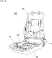
- the vehicle seat 100 is provided with a seatback 1 that supports the back of an occupant, a seat cushion 2 on which the occupant is seated, and a headrest 3 that supports the head of the occupant.
- the vehicle seat 100 is, for example, a driver seat or passenger seat, but may be a rear seat.
- the seat frame 10 and the seating frame 20 are obtained by processing a metal component or hard resin, and are mutually connected via a reclining mechanism 4.
- the seating frame 20 has a pair of side frames 22, 22 spaced apart on the left and right, and a seat pan 24 (see FIG. 4C ) is bridged between the pair of side frames 22, 22.
- the seat cushion 2 has, for example, a seat pad made of a urethane foam material or the like covering a surface and perimeter of the seating frame 20, and a seat cover made of leather, fabric or the like covering a surface of the seat pad.
- An upper surface of the seat cover configures a surface on which the occupant sits, in other words, a seat surface 26 of the seat cushion 2.
- the occupant protecting device 30 is provided inside or below the seat cushion 2.
- the occupant protecting device 30 is provided inside the seat cushion 2 and is covered by the seat cover.
- the occupant protecting device 30 may be provided on an upper surface of the seat pan 24.
- the occupant protecting device 30 is provided below the seat cushion 2 instead of inside the seat cushion 2.
- the occupant protecting device 30 is mounted on a bracket secured to the vehicle seat 100 below the seat cushion 2.
- the occupant protecting device 30 is provided with an airbag cushion 32 capable of expansion and deployment, and an inflator 34 (see FIG. 4C ) that supplies gas for expansion and deployment to the interior space 33 of the airbag cushion 32 in the event of a vehicle emergency.
- a vehicle emergency is a frontal collision of a vehicle.
- the inflator 34 is electrically connected to a vehicle side ECU.
- the inflator 34 receives a signal that an impact upon a frontal collision of the vehicle has been detected from the vehicle side ECU and operates to instantly supply the gas to the airbag cushion 32.
- the inflator 34 can be one of various types of inflators, such as inflators filled with a gas generating agent, compressed gas, or both, and the like.
- the inflator 34 has an igniting device at an open end portion of a cylindrical body with a bottom. Furthermore, when a gas generating agent in the cylindrical body is ignited using the igniting device, gas is generated, and the gas for expansion and deployment is supplied into the airbag cushion 32 from a plurality of injection holes located on a peripheral surface of the cylindrical body.
- the airbag cushion 32 is a bag body and expands and deploys by receiving the supply of gas from the inflator 34.
- the airbag cushion 32 is formed, for example, by joining (sewing or adhering) a plurality of pieces of base fabric made of a non-woven fabric or the like at appropriate positions.
- the airbag cushion 32 has a lower panel 40, an upper panel 42, and mutually opposing side panels 44a, 44b (see: FIG. 3C ). Furthermore, the panels 40, 42, 44a, 44b are made of a non-woven fabric and are joined by sewing.
- the lower panel 40 is formed in, for example, a rectangular shape.
- the lower panel 40 has a front mounting hole 51, rear mounting holes 52, 52 and a center mounting hole 53.
- the front mounting hole 51 is formed at the center in the left-right direction in the front end portion of the lower panel 40.
- the rear mounting holes 52, 52 are formed in a rear end portion of the lower panel 40 so as to be spaced apart from each other in the left-right direction.
- the center mounting hole 53 may be formed at any position between the front mounting hole 51 and the rear mounting holes 52, 52 in the front-rear direction and the left-right direction of the lower panel 40.
- the holes are formed at an optimum position as appropriate in accordance with the size of the inflator 34 to be used, the pitch of the stud bolts (34a to be described later), and the layout of the vehicle seat.
- the center mounting hole 53 can be formed in the center portion in the front-rear direction and the left-right direction of the lower panel 40, the center mounting hole 53 is preferably formed in a center portion.
- the positions of the front mounting hole 51 and the rear mounting holes 52, 52 are, for example, at the apexes of an isosceles triangle, and the center mounting hole 53 is positioned on the bisector of the isosceles triangle.
- the front mounting holes 51, rear mounting holes 52, 52 and center mounting holes 53 are holes where fasteners are used to attach the lower panel 40 to a prescribed position on the vehicle seat 100 side.
- the fastener is, for example, a bolt, rivet, or the like.
- the center mounting hole 53 may constitute a mounting point (third mounting point) for attaching the inflator 34 to the vehicle seat 100 side together with the lower panel 40.
- the inflator is provided on the lower panel 40 with the axial direction of the cylindrical body aligned with the left-right direction.
- a stud bolt 34a protruding from an outer peripheral portion of the cylindrical body (see: FIG.
- the upper panel 42 is formed in, for example, a rectangular shape.
- the upper panel 42 is formed with a length in the front-rear direction of the vehicle seat 100 that is longer than the length of the lower panel 40. In terms of length in the left-right direction, the upper panel 42 and the lower panel 40 are the same or substantially the same.
- the upper panel 42 has a front mounting hole 61 and rear mounting holes 62, 62.
- the front mounting hole 61 is formed at the center in the left-right direction in the front end portion of the upper panel 42.
- the rear mounting holes 62, 62 are formed in a rear end portion of the upper panel 42 so as to be spaced apart from each other in the left-right direction.
- the front mounting hole 61 and the rear mounting holes 62, 62 are holes where fasteners are used to attach the upper panel 42 to a prescribed position on the vehicle seat 100 side.
- the positions in the left-right direction of the front mounting hole 61 and the rear mounting holes 62, 62 of the upper panel 42 are the same as the positions of the front mounting hole 51 and the rear mounting holes 52, 52 of the lower panel 40.
- the side panels 44a, 44b are formed, for example, in shapes that are mutually paired (symmetrical shapes). Furthermore, the side panels 44a, 44b are formed such that the height (dimension in the up-down direction) of the rear side portion 72 is larger than the height of the front side portion 71.
- the side panels 44a, 44b are joined to the lower panel 40 and the upper panel 42. Specifically, the side panels 44a, 44b are sewn to the lower panel 40 and the upper panel 42, with seam lines 73a, 73b along a perimeter part.
- the occupant protecting device 30 accommodates the inflators 34 in the airbag cushions 32 and is mounted on the seat pan 24.
- the stud bolt 34a of the inflator 34 is fastened and secured to the seat pan 24 by a nut via the center mounting hole 53 of the lower panel 40.
- the lower panel 40 and the upper panel 42 are attached to the front securing position 91 of the seat pan 24 via the fastener 81 inserted through the front mounting holes 51, 61.
- the lower panel 40 and the upper panel 42 are mounted to a rear securing position 92 of the seat pan 24 via fasteners 82, 82 inserted through the rear mounting holes 52, 52 and 62, 62.
- the front securing position 91 and the rear securing position 92 are, for example, positions of securing holes formed in the seat pan 24. Note that in relation to an occupant seated in a regular posture, the rear securing position 92 is below a portion of a thigh of the occupant near the buttocks.
- the airbag cushion 32 has a front mounting point 101 (first mounting point) that is mounted to the vehicle seat 100 side, and two rear mounting points 102, 102 (second mounting points) that are mounted to the vehicle seat 100 side on the rear side of the front mounting point 101.
- the front mounting points 101 are constituted by the front mounting holes 51 and 61 of the lower panel 40 and the upper panel 42
- the rear mounting points 102 are constituted by the rear mounting holes 52 and 62 of the lower panel 40 and the upper panel 42.
- the distance between the front securing position 91 and the rear securing position 92 in the seat pan 24 in the front-rear direction is the same as the distance between the front mounting hole 51 and the rear mounting hole 52 in the lower panel 40 in the front-rear direction. Therefore, the lower panel 40 mounted to the seat pan 24 is in a flattened state between the front and rear mounting points 101, 102.
- the upper panel 42 which is longer in the front-rear direction than the lower panel 40, will sag or can be folded back between the front and rear mounting points 101, 102.
- the upper panel 42 is flattened and unfolded such that the fold is not visible in plan view (see FIG. 4B ), and is folded inward at the positions of the fasteners 81, 82 (at the front and rear mounting points 101, 102), and has a partially overlapping portion between the front and rear mounting points 101, 102.
- the lower panel 40 and the upper panel 42 are mutually joined by sewing proximal to the front mounting point 101 and the rear mounting point 102, respectively.
- the sewing point (joining point) 111 between the lower panel 40 and the upper panel 42 proximal to the front mounting point 101 is positioned on the rear side of the front mounting point 101.
- the sewing point 111 is positioned, for example, approximately several centimeters from the front mounting point 101.
- the front mounting point 101 is positioned to the outer side (front side) of the sewing point 111, and therefore is positioned in a non-expanding portion of the airbag cushion 32.
- the sewing point (joining point) 112 between the lower panel 40 and the upper panel 42 proximal to the rear mounting point 102 is positioned to the front side of the rear mounting point 102.
- the sewing point 112 is positioned, for example, a few centimeters from the rear mounting point 102.
- the rear mounting point 102 is positioned to the outer side (rear side) of the sewing point 112, and thus is positioned in a non-expanding portion of the airbag cushion 32.
- the lower panel 40 and the upper panel 42 are sewn together at the sewing points 111, 112 in the front-rear direction, while the side panels 44a, 44b are sewn together with the lower panel 40 and the upper panel 42 in the left-right direction. Furthermore, the lower panel 40, upper panel 42 and side panels 44a, 44b demarcate the interior space 33 of the airbag cushion 32.
- the left and right side portions of the lower panel 40 and the upper panel 42 may be bound with tape 121a, 121b as illustrated in FIG. 4A .
- the occupant protecting device 30 can easily be stored.
- the tape 121a, 121b may be formed so as to be easily broken by the expansion and deployment of the airbag cushion 32, and the occupant protecting device 30 may be mounted to the seat pan 24 while bound by the tape 121a, 121b.
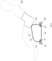
- FIG. 5 illustrates the airbag cushion 32 after expanding and deploying.
- the airbag cushion 32 expands and deploys primarily between the front and rear mounting points 101, 102. Due to the sagging or folding of the upper panel 42 during mounting, the airbag cushion 32 expands upward between the front and rear mounting points 101, 102.
- the height (upward expansion) of the rear side portion 132 is greater than the front side portion 131 in the front-rear direction of the vehicle seat 100, when viewed from the side portion direction of the vehicle seat 100 (left-right direction). This is because the side panels 44a, 44b are formed such that the height of the rear side portion 72 is larger than the height of the front side portion 71.
- the rear mounting point 102 of the airbag cushion 32 is positioned below the portion of the thigh of the occupant 200 near the buttocks, in relation to the occupant 200 who is seated on the seating surface 26 in a regular posture. Therefore, the rear side portion 132 of the expanded and deployed airbag cushion 32 lifts the vicinity of the thigh near the buttocks of the occupant 200 via the seating surface 26. In this manner, effective lifting of the knees of the occupant 200 is achieved, and forward movement of the waist of the occupant 200 is suppressed.
- the occupant protecting device 30 includes the airbag cushion 32 and the inflator 34, the airbag cushion 32 includes the lower panel 40, the upper panel 42, and the side panels 44a, 44b defining the interior space, the upper panel 42 is longer than the lower panel 40 in the front-rear direction, and the upper panel 42 and the lower panel 40 are joined to each other proximal to the front mounting point 101 and the rear mounting point 102.
- the upward expansion (stroke or depth) between the front and rear mounting points 101, 102 can be increased while reducing the overall volume when expanded and deployed as compared to an airbag cushion having a conventional 2D shape.
- the use of the side panels 44a, 44b contributes to this effect, and joining of the upper panel 42 and the lower panel 40 proximal to the front mounting point 101 and the rear mounting point 102 is advantageous for deploying the side panels 44a, 44b to the intended amount of stroke. Therefore, the vicinity of the thigh near the buttocks of the occupant 200 seated on the seat surface 26 in a regular posture can be effectively pushed upward with a larger stroke. Therefore, the waist restraining performance of the occupant 200 can be improved.
- the side panels 44a, 44b are formed such that the height of the rear side portion 72 is higher than the height of the front side portion 71 when viewed from the side portion direction of the vehicle seat 100 when the airbag cushion 32 is expanded and deployed. Therefore, the rear side portion 132 of the expanded and deployed airbag cushion 32 expands upward to a relatively large extent. Accordingly, the vicinity of the thigh near the buttocks of the occupant 200 can be pushed up relatively high, and the vicinity of the thigh can be effectively pushed up.
- the front mounting point 101 is provided on the upper panel 42 as well as the lower panel 40. Accordingly, the portion of the airbag cushion 32 proximal to the front mounting point 101 can be prevented from being lifted or being raised more than necessary at the time of expansion and deployment.
- the rear mounting points 102 are provided not only on the lower panel 40 but also on the upper panel 42. Accordingly, the portion of the airbag cushion 32 proximal to the rear mounting point 102 can be prevented from being lifted or being raised more than necessary at the time of expansion and deployment.
- rear mounting points 102, 102 spaced apart in the left-right direction. This configuration also contributes to the portion of the airbag cushion 32 proximal to the rear mounting point 102 being prevented from being lifted or being raised more than necessary at the time of expansion and deployment.
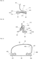
- FIG. 6A illustrates an enlarged view of the first sewing point 111 proximal to the front mounting point 101.
- the lower panel 40 has a tab part 301
- the upper panel 42 has a tab cover part 311 and a folded back part 313.
- the tab part 301 is a portion formed by folding a portion of the lower panel 40 having a prescribed width and extending in the left-right direction of the vehicle seat 100 upward in a mountain fold. Specifically, the tab part 301 is formed by folding a portion of the lower panel 40 on the rear side of the front mounting hole 51 upward or outward for a prescribed length and then folding it downward or inward for a prescribed length.
- the tab cover part 311 is a portion formed by folding a portion of the upper panel 42 having a prescribed width and extending in the left-right direction of the vehicle seat 100 upward in a mountain fold, and is provided so as to cover the tab part 301. Specifically, the tab cover part 311 is formed by folding a portion of the upper panel 42 on the rear side of the front mounting hole 61 upward or outward for a prescribed length and then folding it downward or inward for a prescribed length.
- the tab part 301 is provided inside the tab cover part 311.
- the folded back part 313 is a portion formed on the upper panel 42 and folded upward or outward from the rear end of the tab cover part 311.
- the folded back part 313 is disposed to face the rear side portion of the tab cover part 311.
- the tab part 301, the tab cover part 311, and the folded back part 313 are sewn together with sewing thread 321.
- the tab part 301, the tab cover part 311, and the folded back part 313 are integrally coupled.
- FIG. 6B illustrates an enlarged view of the second sewing point 112 proximal to the rear mounting point 102.
- the lower panel 40 includes a tab part 331 and the upper panel 42 includes a tab cover part 341 and a folded back part 343.
- the tab part 331, the tab cover part 341, and the folded back part 343 are sewn together with the sewing thread 351 at the second sewing point 112 so as to be integrally joined. Note that a detailed description of the tab part 331, the tab cover part 341, and the folded back part 343 at the second sewing point 112 is omitted.
- the portions near the front mounting point 101 and rear mounting point 102 are inhibited from lifting or rising more than necessary.
- the aforementioned sewing at the first sewing point 111 causes the front side portion of the upper panel 42 to be pulled downward as indicated by arrow 361 in FIG. 6C .
- the aforementioned sewing at the second sewing point 112 causes the rear side portion of the upper panel 42 to be pulled downward as indicated by arrow 362 in FIG. 6C .
- FIG. 7A illustrates an enlarged view of the first sewing point 111 proximal to the front mounting point 101.
- the upper panel 42 has a tab part 401.
- the lower panel 40 does not have such a tab part.
- the lower panel 40 has a non-tab part 411 proximal to the front mounting point 101.
- the tab part 401 is a portion formed by folding a portion of the upper panel 42 having a prescribed width and extending in the left-right direction of the vehicle seat 100 in a valley fold. Specifically, the tab part 401 is formed by folding a portion of the upper panel 42 on the rear side of the front mounting hole 61 downward or inward for a prescribed length and then folding it upward or outward for a prescribed length.
- the non-tab part 411 is disposed to face the lower side of the lower side portion of the tab part 401.
- the tab part 401 and the non-tab part 411 are sewn together with sewing thread 421.
- the upper side portion and the lower side portion of the tab part 401 and the non-tab part 411 are integrally joined by sewing together with sewing thread 421.
- FIG. 7B illustrates an enlarged view of the second sewing point 112 proximal to the rear mounting point 102.
- the second sewing point 112 is sewn in the same manner as the second sewing point 112 illustrated in FIG. 6B .
- FIG. 7B the same reference numerals as those in FIG. 6B are shown, and a detailed description thereof is omitted.
- the number of the front mounting points 101 may be one or may be three or more.
- the number of the rear mounting points 102 may be one or may be three or more.
- the front mounting point 101 and the rear mounting point 102 may be provided only on the lower panel 40.
- Vehicle seat 101... Front mounting point (first mounting point), 102... Rear mounting point (second mounting point), 111... First sewing point, 112... Second sewing point, 121a, 121b... Tape, 131... Front side portion, 132... Rear side portion, 200... Occupant, 301... Tab part, 311... Tab cover portion, 313 ... Folded back part, 321... Sewing thread, 331... Tab, 341... Tab cover part, 343... Folded back part, 351... Sewing thread, 361, 362... Arrow, 401... Tab part, 411... Non-tab part, 421... Sewing thread, 431, 432... Arrow
Landscapes
- Engineering & Computer Science (AREA)
- Mechanical Engineering (AREA)
- Aviation & Aerospace Engineering (AREA)
- Transportation (AREA)
- Physics & Mathematics (AREA)
- Fluid Mechanics (AREA)
- Air Bags (AREA)
Applications Claiming Priority (2)
| Application Number | Priority Date | Filing Date | Title |
|---|---|---|---|
| JP2020120434 | 2020-07-14 | ||
| PCT/JP2021/021840 WO2022014207A1 (fr) | 2020-07-14 | 2021-06-09 | Dispositif de protection d'occupant |
Publications (1)
| Publication Number | Publication Date |
|---|---|
| EP4183638A1 true EP4183638A1 (fr) | 2023-05-24 |
Family
ID=79555146
Family Applications (1)
| Application Number | Title | Priority Date | Filing Date |
|---|---|---|---|
| EP21842425.7A Pending EP4183638A1 (fr) | 2020-07-14 | 2021-06-09 | Dispositif de protection d'occupant |
Country Status (5)
| Country | Link |
|---|---|
| EP (1) | EP4183638A1 (fr) |
| JP (1) | JP7411807B2 (fr) |
| KR (1) | KR20230037603A (fr) |
| CN (1) | CN115956034A (fr) |
| WO (1) | WO2022014207A1 (fr) |
Families Citing this family (1)
| Publication number | Priority date | Publication date | Assignee | Title |
|---|---|---|---|---|
| JP7217343B2 (ja) * | 2019-04-22 | 2023-02-02 | オートリブ ディベロップメント エービー | 乗員保護装置 |
Family Cites Families (8)
| Publication number | Priority date | Publication date | Assignee | Title |
|---|---|---|---|---|
| JP4674468B2 (ja) * | 2004-02-10 | 2011-04-20 | タカタ株式会社 | 乗員保護装置 |
| ATE525241T1 (de) * | 2004-07-01 | 2011-10-15 | Autoliv Dev | Beckenrückhalteairbagvorrichtung und diese verwendende sitzkissenvorrichtung |
| JP5078248B2 (ja) | 2005-10-28 | 2012-11-21 | タカタ株式会社 | 乗員拘束装置 |
| JP2007320543A (ja) | 2006-06-05 | 2007-12-13 | Autoliv Development Ab | 車両用シートクッションエアバッグ装置 |
| JP5530607B2 (ja) * | 2008-08-27 | 2014-06-25 | トヨタ自動車株式会社 | クッションエアバッグ装置を内蔵した車両用シート |
| JP5545282B2 (ja) * | 2011-09-30 | 2014-07-09 | 豊田合成株式会社 | シートクッションエアバッグ装置 |
| KR102207570B1 (ko) * | 2014-09-26 | 2021-01-26 | 현대모비스 주식회사 | 시트쿠션 에어백장치의 쿠션 |
| JP6958506B2 (ja) * | 2018-07-31 | 2021-11-02 | 豊田合成株式会社 | シートクッションエアバッグ装置 |
-
2021
- 2021-06-09 KR KR1020237004548A patent/KR20230037603A/ko active Search and Examination
- 2021-06-09 EP EP21842425.7A patent/EP4183638A1/fr active Pending
- 2021-06-09 WO PCT/JP2021/021840 patent/WO2022014207A1/fr unknown
- 2021-06-09 JP JP2022536173A patent/JP7411807B2/ja active Active
- 2021-06-09 CN CN202180042274.5A patent/CN115956034A/zh active Pending
Also Published As
| Publication number | Publication date |
|---|---|
| JP7411807B2 (ja) | 2024-01-11 |
| WO2022014207A1 (fr) | 2022-01-20 |
| KR20230037603A (ko) | 2023-03-16 |
| US20230256928A1 (en) | 2023-08-17 |
| CN115956034A (zh) | 2023-04-11 |
| JPWO2022014207A1 (fr) | 2022-01-20 |
Similar Documents
| Publication | Publication Date | Title |
|---|---|---|
| JP6919383B2 (ja) | サイドエアバッグ装置を搭載した車両用シート | |
| USRE43353E1 (en) | Divided airbag system | |
| US11833990B2 (en) | Side airbag device, vehicle seat provided with same, and method for manufacturing side airbag device | |
| KR102625278B1 (ko) | 사이드 에어백 장치 및 사이드 에어백 장치의 제조 방법 | |
| JP2011025909A (ja) | サイドエアバッグ装置 | |
| CN111731218B (zh) | 气囊系统 | |
| JP6806000B2 (ja) | シート付下肢拘束エアバッグ装置 | |
| US20200130629A1 (en) | Side airbag device | |
| US11254276B2 (en) | Side airbag apparatus and vehicle seat including the same | |
| US11865987B2 (en) | Occupant protection device | |
| EP4183638A1 (fr) | Dispositif de protection d'occupant | |
| CN111086478B (zh) | 侧面安全气囊装置 | |
| US11993218B2 (en) | Occupant protection device | |
| US20230406254A1 (en) | Side airbag device | |
| JP7205500B2 (ja) | ファーサイドエアバッグ装置 | |
| CN109795440B (zh) | 车辆用侧气囊装置 | |
| US11766981B2 (en) | Occupant protection device | |
| JP7279257B2 (ja) | サイドエアバッグ装置 | |
| JP2018188123A (ja) | クッションエアバッグ装置を内蔵した車両用シート、及びクッションエアバッグ | |
| EP4119402A1 (fr) | Dispositif d'airbag latéral | |
| WO2024062969A1 (fr) | Siège de véhicule | |
| EP1939050A1 (fr) | Dispositif de retenue des occupants d'un véhicule | |
| JP2024043671A (ja) | 車両用シート | |
| JP2023094959A (ja) | エアバッグ装置 | |
| JP2022110957A (ja) | 車両用サイドエアバッグ |
Legal Events
| Date | Code | Title | Description |
|---|---|---|---|
| STAA | Information on the status of an ep patent application or granted ep patent |
Free format text: STATUS: THE INTERNATIONAL PUBLICATION HAS BEEN MADE |
|
| PUAI | Public reference made under article 153(3) epc to a published international application that has entered the european phase |
Free format text: ORIGINAL CODE: 0009012 |
|
| STAA | Information on the status of an ep patent application or granted ep patent |
Free format text: STATUS: REQUEST FOR EXAMINATION WAS MADE |
|
| 17P | Request for examination filed |
Effective date: 20230203 |
|
| AK | Designated contracting states |
Kind code of ref document: A1 Designated state(s): AL AT BE BG CH CY CZ DE DK EE ES FI FR GB GR HR HU IE IS IT LI LT LU LV MC MK MT NL NO PL PT RO RS SE SI SK SM TR |
|
| DAV | Request for validation of the european patent (deleted) | ||
| DAX | Request for extension of the european patent (deleted) |