EP4183357B1 - Medizinisches instrument - Google Patents
Medizinisches instrument Download PDFInfo
- Publication number
- EP4183357B1 EP4183357B1 EP21209026.0A EP21209026A EP4183357B1 EP 4183357 B1 EP4183357 B1 EP 4183357B1 EP 21209026 A EP21209026 A EP 21209026A EP 4183357 B1 EP4183357 B1 EP 4183357B1
- Authority
- EP
- European Patent Office
- Prior art keywords
- instrument
- channel
- closure
- instrument according
- anyone
- Prior art date
- Legal status (The legal status is an assumption and is not a legal conclusion. Google has not performed a legal analysis and makes no representation as to the accuracy of the status listed.)
- Active
Links
Images
Classifications
-
- A—HUMAN NECESSITIES
- A61—MEDICAL OR VETERINARY SCIENCE; HYGIENE
- A61B—DIAGNOSIS; SURGERY; IDENTIFICATION
- A61B18/00—Surgical instruments, devices or methods for transferring non-mechanical forms of energy to or from the body
- A61B18/04—Surgical instruments, devices or methods for transferring non-mechanical forms of energy to or from the body by heating
- A61B18/12—Surgical instruments, devices or methods for transferring non-mechanical forms of energy to or from the body by heating by passing a current through the tissue to be heated, e.g. high-frequency current
-
- A—HUMAN NECESSITIES
- A61—MEDICAL OR VETERINARY SCIENCE; HYGIENE
- A61B—DIAGNOSIS; SURGERY; IDENTIFICATION
- A61B1/00—Instruments for performing medical examinations of the interior of cavities or tubes of the body by visual or photographical inspection, e.g. endoscopes; Illuminating arrangements therefor
- A61B1/00064—Constructional details of the endoscope body
- A61B1/00071—Insertion part of the endoscope body
- A61B1/0008—Insertion part of the endoscope body characterised by distal tip features
- A61B1/00096—Optical elements
-
- A—HUMAN NECESSITIES
- A61—MEDICAL OR VETERINARY SCIENCE; HYGIENE
- A61B—DIAGNOSIS; SURGERY; IDENTIFICATION
- A61B5/00—Measuring for diagnostic purposes; Identification of persons
- A61B5/0059—Measuring for diagnostic purposes; Identification of persons using light, e.g. diagnosis by transillumination, diascopy, fluorescence
- A61B5/0082—Measuring for diagnostic purposes; Identification of persons using light, e.g. diagnosis by transillumination, diascopy, fluorescence adapted for particular medical purposes
- A61B5/0084—Measuring for diagnostic purposes; Identification of persons using light, e.g. diagnosis by transillumination, diascopy, fluorescence adapted for particular medical purposes for introduction into the body, e.g. by catheters
-
- A—HUMAN NECESSITIES
- A61—MEDICAL OR VETERINARY SCIENCE; HYGIENE
- A61B—DIAGNOSIS; SURGERY; IDENTIFICATION
- A61B17/00—Surgical instruments, devices or methods
- A61B17/34—Trocars; Puncturing needles
- A61B17/3498—Valves therefor, e.g. flapper valves, slide valves
-
- A—HUMAN NECESSITIES
- A61—MEDICAL OR VETERINARY SCIENCE; HYGIENE
- A61B—DIAGNOSIS; SURGERY; IDENTIFICATION
- A61B1/00—Instruments for performing medical examinations of the interior of cavities or tubes of the body by visual or photographical inspection, e.g. endoscopes; Illuminating arrangements therefor
- A61B1/00163—Optical arrangements
- A61B1/00165—Optical arrangements with light-conductive means, e.g. fibre optics
-
- A—HUMAN NECESSITIES
- A61—MEDICAL OR VETERINARY SCIENCE; HYGIENE
- A61B—DIAGNOSIS; SURGERY; IDENTIFICATION
- A61B1/00—Instruments for performing medical examinations of the interior of cavities or tubes of the body by visual or photographical inspection, e.g. endoscopes; Illuminating arrangements therefor
- A61B1/012—Instruments for performing medical examinations of the interior of cavities or tubes of the body by visual or photographical inspection, e.g. endoscopes; Illuminating arrangements therefor characterised by internal passages or accessories therefor
- A61B1/015—Control of fluid supply or evacuation
-
- A—HUMAN NECESSITIES
- A61—MEDICAL OR VETERINARY SCIENCE; HYGIENE
- A61B—DIAGNOSIS; SURGERY; IDENTIFICATION
- A61B17/00—Surgical instruments, devices or methods
- A61B17/00234—Surgical instruments, devices or methods for minimally invasive surgery
-
- A—HUMAN NECESSITIES
- A61—MEDICAL OR VETERINARY SCIENCE; HYGIENE
- A61B—DIAGNOSIS; SURGERY; IDENTIFICATION
- A61B18/00—Surgical instruments, devices or methods for transferring non-mechanical forms of energy to or from the body
- A61B18/02—Surgical instruments, devices or methods for transferring non-mechanical forms of energy to or from the body by cooling, e.g. cryogenic techniques
-
- A—HUMAN NECESSITIES
- A61—MEDICAL OR VETERINARY SCIENCE; HYGIENE
- A61B—DIAGNOSIS; SURGERY; IDENTIFICATION
- A61B18/00—Surgical instruments, devices or methods for transferring non-mechanical forms of energy to or from the body
- A61B18/04—Surgical instruments, devices or methods for transferring non-mechanical forms of energy to or from the body by heating
- A61B18/12—Surgical instruments, devices or methods for transferring non-mechanical forms of energy to or from the body by heating by passing a current through the tissue to be heated, e.g. high-frequency current
- A61B18/14—Probes or electrodes therefor
- A61B18/1492—Probes or electrodes therefor having a flexible, catheter-like structure, e.g. for heart ablation
-
- A—HUMAN NECESSITIES
- A61—MEDICAL OR VETERINARY SCIENCE; HYGIENE
- A61B—DIAGNOSIS; SURGERY; IDENTIFICATION
- A61B18/00—Surgical instruments, devices or methods for transferring non-mechanical forms of energy to or from the body
- A61B18/18—Surgical instruments, devices or methods for transferring non-mechanical forms of energy to or from the body by applying electromagnetic radiation, e.g. microwaves
- A61B18/20—Surgical instruments, devices or methods for transferring non-mechanical forms of energy to or from the body by applying electromagnetic radiation, e.g. microwaves using laser
-
- A—HUMAN NECESSITIES
- A61—MEDICAL OR VETERINARY SCIENCE; HYGIENE
- A61B—DIAGNOSIS; SURGERY; IDENTIFICATION
- A61B50/00—Containers, covers, furniture or holders specially adapted for surgical or diagnostic appliances or instruments, e.g. sterile covers
-
- A—HUMAN NECESSITIES
- A61—MEDICAL OR VETERINARY SCIENCE; HYGIENE
- A61B—DIAGNOSIS; SURGERY; IDENTIFICATION
- A61B90/00—Instruments, implements or accessories specially adapted for surgery or diagnosis and not covered by any of the groups A61B1/00 - A61B50/00, e.g. for luxation treatment or for protecting wound edges
- A61B90/30—Devices for illuminating a surgical field, the devices having an interrelation with other surgical devices or with a surgical procedure
-
- A—HUMAN NECESSITIES
- A61—MEDICAL OR VETERINARY SCIENCE; HYGIENE
- A61B—DIAGNOSIS; SURGERY; IDENTIFICATION
- A61B18/00—Surgical instruments, devices or methods for transferring non-mechanical forms of energy to or from the body
- A61B18/04—Surgical instruments, devices or methods for transferring non-mechanical forms of energy to or from the body by heating
- A61B18/042—Surgical instruments, devices or methods for transferring non-mechanical forms of energy to or from the body by heating using additional gas becoming plasma
-
- A—HUMAN NECESSITIES
- A61—MEDICAL OR VETERINARY SCIENCE; HYGIENE
- A61B—DIAGNOSIS; SURGERY; IDENTIFICATION
- A61B18/00—Surgical instruments, devices or methods for transferring non-mechanical forms of energy to or from the body
- A61B18/18—Surgical instruments, devices or methods for transferring non-mechanical forms of energy to or from the body by applying electromagnetic radiation, e.g. microwaves
- A61B18/20—Surgical instruments, devices or methods for transferring non-mechanical forms of energy to or from the body by applying electromagnetic radiation, e.g. microwaves using laser
- A61B18/22—Surgical instruments, devices or methods for transferring non-mechanical forms of energy to or from the body by applying electromagnetic radiation, e.g. microwaves using laser the beam being directed along or through a flexible conduit, e.g. an optical fibre; Couplings or hand-pieces therefor
-
- A—HUMAN NECESSITIES
- A61—MEDICAL OR VETERINARY SCIENCE; HYGIENE
- A61B—DIAGNOSIS; SURGERY; IDENTIFICATION
- A61B17/00—Surgical instruments, devices or methods
- A61B2017/00017—Electrical control of surgical instruments
- A61B2017/00022—Sensing or detecting at the treatment site
- A61B2017/00057—Light
- A61B2017/00061—Light spectrum
-
- A—HUMAN NECESSITIES
- A61—MEDICAL OR VETERINARY SCIENCE; HYGIENE
- A61B—DIAGNOSIS; SURGERY; IDENTIFICATION
- A61B17/00—Surgical instruments, devices or methods
- A61B17/00234—Surgical instruments, devices or methods for minimally invasive surgery
- A61B2017/00292—Surgical instruments, devices or methods for minimally invasive surgery mounted on or guided by flexible, e.g. catheter-like, means
- A61B2017/00296—Surgical instruments, devices or methods for minimally invasive surgery mounted on or guided by flexible, e.g. catheter-like, means mounted on an endoscope
-
- A—HUMAN NECESSITIES
- A61—MEDICAL OR VETERINARY SCIENCE; HYGIENE
- A61B—DIAGNOSIS; SURGERY; IDENTIFICATION
- A61B17/00—Surgical instruments, devices or methods
- A61B17/00234—Surgical instruments, devices or methods for minimally invasive surgery
- A61B2017/00292—Surgical instruments, devices or methods for minimally invasive surgery mounted on or guided by flexible, e.g. catheter-like, means
- A61B2017/0034—Surgical instruments, devices or methods for minimally invasive surgery mounted on or guided by flexible, e.g. catheter-like, means adapted to be inserted through a working channel of an endoscope
-
- A—HUMAN NECESSITIES
- A61—MEDICAL OR VETERINARY SCIENCE; HYGIENE
- A61B—DIAGNOSIS; SURGERY; IDENTIFICATION
- A61B17/00—Surgical instruments, devices or methods
- A61B2017/00831—Material properties
- A61B2017/00862—Material properties elastic or resilient
-
- A—HUMAN NECESSITIES
- A61—MEDICAL OR VETERINARY SCIENCE; HYGIENE
- A61B—DIAGNOSIS; SURGERY; IDENTIFICATION
- A61B18/00—Surgical instruments, devices or methods for transferring non-mechanical forms of energy to or from the body
- A61B2018/00636—Sensing and controlling the application of energy
- A61B2018/00904—Automatic detection of target tissue
-
- A—HUMAN NECESSITIES
- A61—MEDICAL OR VETERINARY SCIENCE; HYGIENE
- A61B—DIAGNOSIS; SURGERY; IDENTIFICATION
- A61B18/00—Surgical instruments, devices or methods for transferring non-mechanical forms of energy to or from the body
- A61B2018/00982—Surgical instruments, devices or methods for transferring non-mechanical forms of energy to or from the body combined with or comprising means for visual or photographic inspections inside the body, e.g. endoscopes
-
- A—HUMAN NECESSITIES
- A61—MEDICAL OR VETERINARY SCIENCE; HYGIENE
- A61B—DIAGNOSIS; SURGERY; IDENTIFICATION
- A61B50/00—Containers, covers, furniture or holders specially adapted for surgical or diagnostic appliances or instruments, e.g. sterile covers
- A61B2050/005—Containers, covers, furniture or holders specially adapted for surgical or diagnostic appliances or instruments, e.g. sterile covers with a lid or cover
-
- A—HUMAN NECESSITIES
- A61—MEDICAL OR VETERINARY SCIENCE; HYGIENE
- A61B—DIAGNOSIS; SURGERY; IDENTIFICATION
- A61B90/00—Instruments, implements or accessories specially adapted for surgery or diagnosis and not covered by any of the groups A61B1/00 - A61B50/00, e.g. for luxation treatment or for protecting wound edges
- A61B90/30—Devices for illuminating a surgical field, the devices having an interrelation with other surgical devices or with a surgical procedure
- A61B2090/306—Devices for illuminating a surgical field, the devices having an interrelation with other surgical devices or with a surgical procedure using optical fibres
-
- A—HUMAN NECESSITIES
- A61—MEDICAL OR VETERINARY SCIENCE; HYGIENE
- A61B—DIAGNOSIS; SURGERY; IDENTIFICATION
- A61B90/00—Instruments, implements or accessories specially adapted for surgery or diagnosis and not covered by any of the groups A61B1/00 - A61B50/00, e.g. for luxation treatment or for protecting wound edges
- A61B90/36—Image-producing devices or illumination devices not otherwise provided for
- A61B90/361—Image-producing devices, e.g. surgical cameras
- A61B2090/3614—Image-producing devices, e.g. surgical cameras using optical fibre
-
- A—HUMAN NECESSITIES
- A61—MEDICAL OR VETERINARY SCIENCE; HYGIENE
- A61B—DIAGNOSIS; SURGERY; IDENTIFICATION
- A61B2218/00—Details of surgical instruments, devices or methods for transferring non-mechanical forms of energy to or from the body
- A61B2218/001—Details of surgical instruments, devices or methods for transferring non-mechanical forms of energy to or from the body having means for irrigation and/or aspiration of substances to and/or from the surgical site
- A61B2218/002—Irrigation
- A61B2218/005—Irrigation using gas or vapor, e.g. for protection or purging
-
- A—HUMAN NECESSITIES
- A61—MEDICAL OR VETERINARY SCIENCE; HYGIENE
- A61B—DIAGNOSIS; SURGERY; IDENTIFICATION
- A61B2218/00—Details of surgical instruments, devices or methods for transferring non-mechanical forms of energy to or from the body
- A61B2218/001—Details of surgical instruments, devices or methods for transferring non-mechanical forms of energy to or from the body having means for irrigation and/or aspiration of substances to and/or from the surgical site
- A61B2218/007—Aspiration
-
- A—HUMAN NECESSITIES
- A61—MEDICAL OR VETERINARY SCIENCE; HYGIENE
- A61M—DEVICES FOR INTRODUCING MEDIA INTO, OR ONTO, THE BODY; DEVICES FOR TRANSDUCING BODY MEDIA OR FOR TAKING MEDIA FROM THE BODY; DEVICES FOR PRODUCING OR ENDING SLEEP OR STUPOR
- A61M25/00—Catheters; Hollow probes
- A61M25/0067—Catheters; Hollow probes characterised by the distal end, e.g. tips
- A61M25/0074—Dynamic characteristics of the catheter tip, e.g. openable, closable, expandable or deformable
- A61M2025/0079—Separate user-activated means, e.g. guidewires, guide tubes, balloon catheters or sheaths, for sealing off an orifice, e.g. a lumen or side holes, of a catheter
Definitions
- the invention relates to a medical instrument for the medical or surgical treatment of a human or animal patient.
- the invention relates to such an instrument that contains a light-guiding device configured to conduct light away from a site of action of the instrument or, additionally or alternatively, to conduct light to a site of action of the instrument.
- From the EP2 113 190 is an arrangement consisting of a surgical instrument and a trocar through whose working channel the instrument can be pushed.
- the instrument contains a light-guiding device by means of which light can be absorbed or emitted at the distal end of the instrument.
- the trocar is provided at its distal end with one or more protective elements that block the working channel and thus prevent fluids from entering the working channel. When moved distally, the instrument can push the protective element aside in order to obtain a clear view of the target area of the instrument.
- the EP 3 195 824 A1 proposes an instrument with a channel in which an optical fiber is arranged so as to be longitudinally movable.
- the optical fiber has a light-emitting surface at its distal end from which a Laser beam can escape.
- the channel is provided at its distal end with a wiping element 21, which closes the channel when the fiber is retracted and prevents fine fluid droplets from entering the channel and deposition from the light exit surface of the fiber. As the fiber is advanced, the wiping element wipes the light exit surface, thus cleaning it.
- EP 1 773 223 B1 which illustrates a device for argon plasma coagulation, the gas-carrying channel of which is provided with closure elements.
- WO 96/01132 A1 An instrument with an elongated shaft is known, at the end of which is a closure element. An elongated optical element can be pushed through the hollow shaft, which is designed to view an area in front of the tip of the instrument. The optical element can be moved axially and can be pushed out of or retracted into a distal opening of the instrument. Flexible wings are used to close the opening; when relaxed, they rest against one another and can be pushed apart by the optical rod-shaped element.
- the instrument according to the invention comprises an instrument body in which at least one channel is formed, which has a distal end and a proximal end.
- a channel can also be formed "on" the instrument, by being formed in a separate element that is connected to the body of the instrument, e.g., by one or more clamps (e.g., spring clips).
- clamps e.g., spring clips
- the channel can extend, in particular, from the distal end of the instrument to its proximal end, at which a connection device can be formed to connect the proximal end of the instrument and, with it, also the channel to a fluid source.
- the fluid source can be configured, in particular, to supply a gaseous fluid, such as air, a pure gas, for example nitrogen, argon, carbon dioxide or another desired gas, or a mixture of one or more gases.
- the fluid source can further be configured to supply the gaseous fluid at a predetermined pressure in order to establish a predetermined gas pressure and/or a predetermined gas flow in the channel.
- the instrument body can have a plurality of channels to deliver or receive fluids at the distal end of the instrument.
- the instrument can have one or more gas delivery channels and/or one or more suction channels.
- the at least one channel has a fluid outlet opening at its distal end.
- This fluid outlet opening In the instrument according to the invention, there is also a light transmission opening through which light can enter and/or exit.
- This light transmission opening preferably faces an active site of the instrument, in which, for example, an electrode held on the instrument can be arranged. Multiple electrodes can also be provided. One or more such electrodes can be arranged stationary or movable on the instrument.
- the at least one electrode can also be connected to an electrical source, for example a high-frequency voltage source, in order to act on biological tissue by means of current.
- the electrical source is designed to provide a voltage and a current that are large enough to generate a spark at the electrode.
- the electrode is, for example, a cutting electrode, the voltage a cutting voltage, and the current flowing from the electrode to the tissue a cutting current. The resulting spark emits light that shines into the channel via the light transmission opening.
- an optical element having a light transmission window is arranged in the channel at a distance from the distal end of the channel.
- the light transmission window, and with it the optical element, are arranged immovably within the channel.
- the optical element is immovably connected to the body of the instrument.
- the light transmission window of the optical element is spaced proximally from the light transmission opening formed by the gas outlet opening of the channel.
- a closure device is arranged between the light transmission window and the light transmission opening, said closure device having a closure member which can be moved between an open position and a closed position. In its closed position, the closure member is designed to block the channel against the passage of particles and in particular liquid droplets and thus to shield the light transmission window of the optical element from contamination.
- the closure member is further designed to release the channel in the open position both for the passage of gases and for the passage of light.
- the closure member is not controlled by a movement of the optical element, even if the latter is arranged to be movable in the channel. There is no operative connection between the optical element and the closure device and in particular its closure member.
- the optical element and the closure member preferably do not touch one another.
- the optical element is arranged at a fixed distance from the light exit opening of the channel.
- the optical element may, in particular, comprise or be formed by a light-guiding device.
- the optical element may be a single optical fiber or a bundle of optical fibers, wherein the fiber or fibers each have a light transmission window at their respective distal end.
- the light transmission window can be used to transmit light for analytical and/or therapeutic purposes to shine onto the tissue to be treated.
- the light transmission window can also be used to capture light generated during tissue treatment, e.g., light from a spark burning between an electrode and the tissue, and feed it into a light analysis device.
- the light analysis can, for example, be used to identify the tissue undergoing treatment. Other parameters (e.g., spark stability or similar) can also be recorded.
- Optical emission spectroscopy (OES), optical coherence tomography (OCT), Raman spectroscopy, photoacoustic analysis, or other optical methods can be used for optical evaluation of the light, e.g., for tissue analysis.
- the closure member can have one end fixedly mounted on the instrument, from which the remaining part of the closure member extends.
- the mounted end can be connected to the instrument in a fixed or movable manner, e.g., pivotable manner.
- the remaining part of the closure member is thus movably mounted on the instrument and can thus be moved back and forth between an open position and a closed position.
- the closure member can be rigid or elastic, stiff or flexible.
- Embodiments are possible that operate with only a single closure element. Embodiments also exist with multiple closure elements, which, for example, are spread apart from one another in the open position and rest against one another in the closed position.
- the closure element or elements can be formed by flexible, elastic lamellae. These can be resiliently biased toward one another to define a conical or pyramidal shape in the closed position, whereby the Contact lines are the surface lines of the cone or edges of the pyramid.
- the slats In the open position, the slats can be spread apart from one another. It is advantageous if the slats are made of a flexible material for this purpose. Additionally or alternatively, the closure member can be made of an expandable material.
- the closure member can then, for example, have the shape of a cone or a pyramid with a small opening at its tip. To open, the material is stretched accordingly so that the opening at the tip of the cone or pyramid enlarges.
- the base of the pyramid or cone can correspond to the channel cross-section.
- the closure member is arranged such that it blocks the channel in the rest position, and can be moved into the open position by the pressure and/or flow of the fluid, particularly gas, present in the channel.
- the closure member can be designed to be pneumatically actuated.
- the channel can be a purge gas channel, wherein the gas pressure of the purge gas or other gas provided by the fluid source is sufficient to open the closure member.
- the light transmission window has a viewing cone that extends through the fluid outlet opening and thus through the light transmission opening.
- the closure member of the closure device is preferably designed such that it blocks the viewing cone in the closed position but releases it in the open position.
- the closure device can be controlled by the fluid passing through the channel, particularly its pressure or flow rate.
- the fluid acts directly on the closure member. which is self-controlled in this respect.
- an externally controlled closure device connected to a mechanical actuation device.
- the mechanical actuation device can be, for example, an electromagnetic actuation device, a pneumatic actuation device, or a manual actuation device.
- the closure member can be mechanically provided with an actuation button of the instrument in order to be moved back and forth in a controlled manner between the open and closed positions.
- An electromechanical or pneumatic actuator can also be provided to move the closure member between the open and closed positions.
- the passage between the light transmission opening and the light transmission window is opened in a controlled and regulated manner by controlling the closure device, either by the gas flow or by other actuating elements or media.
- the opening i.e. the opening of the closure device, can in particular be limited to times when light transmission is actually required.
- the instrument can be designed to open and close the closure device synchronously with the delivery of fluid, for example purge gas, to the site of action of the instrument.
- the instrument and/or its feeding device can be designed to begin the gas delivery through the channel before activation of the HF electrode and to end it only after the end of the activation of the HF electrode.
- the closure device closes the passage from the light transmission opening to the light transmission window, thus preventing contamination of the light transmission window.
- contamination is prevented by the existing gas flow, which carries all contaminating particles or droplets away from the light transmission opening.
- the closure device can have a closure member that is spring-loaded towards its closed position and can be and is moved into the open position by an actuator or the gas flow itself.
- the suction device can be configured to actuate the closure device.
- the instrument can have a suction channel that opens near the distal end of the instrument.
- An actuator connected to the suction channel is then configured to open and close the closure device depending on whether or not there is negative pressure in the suction channel.
- the suction channel can be connected to a suction device that is configured to be activated synchronously with a generator that feeds the electrode.
- the suction device can be configured to be activated before the generator is activated and only deactivated again after the generator is deactivated.
- the closure device is only open while the electrode is energized or b) the closure device is only open while a distally directed purge gas flow is established in the purge gas channel or c) the closure device is only open while a flow in the proximal direction is established in the vent channel.
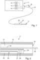
- Figure 1 illustrates an instrument 10 according to the invention, which is connected to a power supply device 11.
- the device 11 is connected to the instrument 10 via a corresponding line 12 and is configured to supply the instrument 10 with at least one operating medium.
- the device 11 can have one or more fluid sources 13, one or more electrical generators 14, and/or one or more suction devices 15, which are connected to the line 12 or the instrument 10 via one or more plugs 16.
- Figure 1 illustrates the instrument 10 as a handheld instrument for open surgical use.
- the invention also extends to instruments of other designs, e.g., laparoscopically inserted instruments or probes that can be inserted into a patient's body through the working channel of an endoscope, a trocar, or through another access.
- the instrument 10 has a distal end 17 and a proximal end 18, which may be formed by the plug 16 or a portion of its lead 12.
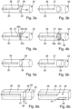
- the distal end 17 of the instrument 10 is illustrated separately in Figure 2. It includes the distal section of an instrument body 19, through which at least one channel 20 extends.
- the channel 20 is, in particular, a fluid-conducting, for example, gas-conducting channel, which preferably extends from the distal end 17 through the instrument 10 and its entire line 12 to the proximal end 18 or plug 16, where it is connected to the gas source 13.
- the instrument 10 can have further channels, such as a suction channel 21, which also extends from the distal end 17 of the instrument 10 to its proximal end 18. or plug 16 and is connected there to the suction device 15.
- other channels and/or further channels can be provided to guide liquids and/or gases to or away from the distal end 17 of the instrument 10 and to allow them to enter or exit there.
- the instrument 10 may include tools for influencing biological tissue.
- a tool may, for example, be an electrode 22 that is held in or at the distal end 17 of the instrument 10 and terminates there, or that protrudes from a gas transfer opening or terminates shortly before it.
- the electrode 22 is connected to the generator 14 via an electrical line 24 that extends through the line 12 to the proximal end 18 or the connector 16.
- multiple electrodes or other tools such as a waterjet tool, a laser tool, or the like, may also be provided.
- the channel 20 has a distal opening, which is a gas outlet opening and simultaneously a light transmission opening 25.
- An optical element 26, for example in the form of a light guide, is preferably arranged immovably in the channel 20 and has a light transmission window 27 at its distal end.
- the light transmission window 27 can be formed by the end face of the optical element 26, i.e., for example, by the end face of an optical fiber.
- the light transmission window 27 and, with it, the optical element 26 are preferably arranged axially immovably in the channel 20.
- the light transmission window 27 is preferably spaced apart from the light transmission opening 25 in the proximal direction.
- a closure device 28 is arranged between the light transmission window 27 and the light transmission opening 25.
- This closure device 28 is configured to open or close the passage from the light transmission opening 25 to the light transmission window 27 in a controlled manner.
- the closure device 28 is controlled by the gas flow in the channel 20 or by other media, but under no circumstances by any movement of the optical element 26, which, as mentioned, is preferably arranged in a stationary manner.
- a first embodiment of the closure device 28 is shown in the Figures 3a and 3b
- the closure device 28 is formed there by an approximately conical closure member 29 made of tensile-elastic material, which has an expandable opening at its tip 30.
- the tip 30 faces the light transfer opening 25.
- the opening at the tip 30 is very narrow or completely closed in the closed state.
- the tensile elasticity of the material of the closure member 29 is so great that the opening 30 can be expanded by the pressure prevailing in the channel 20 to such an extent that the desired gas flow can escape from the light transfer opening 25 and thus the light path from the light transfer opening 25 to the light transfer window 27 is also cleared.
- the closure member 29 is in the open position.
- the closure device 28 comprises several closure members 29a, 29b, 29c which are flexible and, when they lie with their edges against each other, form a cone At its tip 30, the lamella-like closure members 29a, 29b, 29c, etc. meet and thus close the passage from the light transmission opening 25 to the light transmission window 27. If, however, the channel 20 is pressurized with gas, the closure members 29a, 29b, 29c, etc. spread apart, as Figure 4b Thus, the passage through the closure device 28 is open for both gas and light, the closure members 29a, 29b, etc. are in the open position.
- the closure member 29 has a section that is held stationary on the instrument 10. This section is formed by a circular section of the closure member 29, which forms the base of the cone defined by the closure member 28. This section is fixedly connected to the wall of the channel 20. The remaining parts of the conical closure member 29 can be elastically or flexibly deformed and are therefore movable.
- FIGs 5a and 5b A further modified embodiment of the closure device 28 is illustrated, in which the closure member 29 is formed from a foldable, flexible, flaccid material, such as a film tube section. This collapses when no gas is applied to the channel 20 and blocks the channel 20 as an irregularly shaped body. When gas passes through, the closure member 29 unfolds, as shown in Figure 5b and thus allows the passage of light and gas between the light transmission window 27 and the light transmission opening 25. Otherwise, the above description applies accordingly.
- a foldable, flexible, flaccid material such as a film tube section.
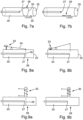
- the drawing is based on a channel with a round cross-section. It is also possible to use However, in some embodiments, the channel 20 may also have cross-sections other than circular, for example, polygonal cross-sections such as triangles, rectangles, hexagons or curvilinear polygons.
- the closure device 28 here comprises a closure member 29 designed as a flap, the outline of which corresponds to the cross-section of the channel 20.
- the flap-like closure member 29 is connected to the instrument or the wall of the channel 20 by an edge 31.
- the edge 31 can be firmly anchored and the closure member 29 can be flexible. Alternatively, the edge 31 can be held like a hinge.
- the closure member 29 blocks the channel 20 and thus the passage between the light transmission window 27 and the light exit opening 25.
- the closure member 29 can be resiliently preloaded to this position. This resilient preload can be provided by the inherent elasticity of the closure member 29 or by a separate spring element.
- the closure member 29 can be assigned a stop against which it rests in the locked position (not shown). This is particularly advantageous in embodiments in which the closure member 29 is held at the edge 31 by a hinge.
- Figure 6b the open position of the closure device 28 is illustrated, in which the closure member 29 is forced from its rest position into the open position by the gas flowing through the channel 20 in the distal direction.
- the actuating device can move the closure member 29 via a suitable gear, illustrated here only schematically by a two-armed lever 34, so that it is in the closed position Figure 8a blocks the passage between the light transmission window 27 and the light transmission opening 25 and in the actuating position according to Figure 8b releases.
- a suitable gear illustrated here only schematically by a two-armed lever 34
- the actuation of the locking device 28 can, as shown in the example of Figures 9a and 9b can be seen, also by other actuators, for example by a magnetic actuator 35, with which the closure member 29 in the closed position according to Figure 9a in the channel 20 and in the open position, as Figure 9b shows, can be positioned outside channel 20.
- a magnetic actuator 35 with which the closure member 29 in the closed position according to Figure 9a in the channel 20 and in the open position, as Figure 9b shows, can be positioned outside channel 20.
- the electrode 22 is preferably located within the field of view of the optical element 26, i.e., in the cone of view emanating from the light transmission window 27 and extending through the light transmission opening 25.
- spark light emanating from the electrode can be detected and forwarded by the optical element 26 to an analysis device, for example, a spectrum analyzer, which can be part of the instrument 11 or can be configured and mounted separately.
- the gas flow advancing through the channel 20 and flowing out of the light transmission opening 25 effectively prevents the deposition of particles, droplets or other contaminants on the light transmission window 27.
- the closure device closes 28.
- contamination continues to occur due to turbulence or the like, for example, due to the activity of the suction device 25, which suctions fluids or other material from the surgical area via the suction channel 21, the light transmission window 27 remains sealed and protected from contamination. This also applies if work continues with the electrode 22 without gas access through the channel 20, thus releasing particles.
- the Figures 8a to 9b The illustrated embodiments of the instrument 10 operate in a similar manner.
- the closure device 28 is always released when the actuating device 33 is activated.
- the activation of the actuating device 33 can take place independently of the activation of the device 11 and the generator 14.
- the channel 20 can be pressurized with gas under low pressure.
- the closure device 28 When the closure device 28 is closed, this can simultaneously block the gas flow and the passage of light.
- the closure device 28 also blocks the passage of contaminants.
- the light path is released.
- the gas flow is released, which prevents the penetration of contaminants. If a gas flow is to be possible even when the closure device 28 is closed, a bypass that is opaque to light can be provided parallel to the closure device 28.
- the closure device 28 is actuated by the magnetic actuator 35 or another suitable electrical actuator.
- the actuator 35 can be energized synchronously with the energization of the electrode 22 or independently of it. The latter, for example, if light from the electrode 22 is only to be recorded occasionally.
- the device 11 is then designed in conjunction with the instrument 10 si, which, in order to record light from the treatment site, for example for spectral analysis of the light, the spectrometer and the actuator 35 are activated simultaneously. This permanently protects the light transmission window 27 from contamination. In the activated state, the gas flow through the channel 20 prevents contamination. When deactivated, the closure device 28 closes and closes the light transmission window 27. This principle applies to all embodiments.
- the invention is not limited to electrosurgical instruments. It can also be used for laser surgical instruments or cryosurgical instruments.
- the optical element 26 can be designed to send a laser beam from the light transmission window 27 through the light transmission opening 25 to the tissue.
- the gas flow in the channel 20 also keeps the light transmission window 27 free of contamination.
- the closure device 28 closes, for example, according to the principles of Figures 8a to 9b .
- the instrument 10 can also be a water jet surgical or other instrument.
- a water injection channel can then be provided to inject the corresponding tissue at the The surgical site should preferably be treated in the field of view of the optical element 26. The previous description otherwise applies accordingly.
- An instrument according to the invention for the medical or surgical treatment of a human or animal patient has at least one tool suitable for influencing a patient, for example an electrode 22, which lies in the field of view of an optical element 26.
- the optical element 26 is arranged in a channel 20 in which a fluid flow directed in the distal direction can be maintained or induced.
- the light transmission window 27 of the optical element 26 is offset proximally from the distal opening 25 of the channel 22.
- a closure device 28 is arranged between the light transmission window 27 and the opening 25 of the channel 20, which blocks the passage of substances, in particular the passage of liquid droplets and particles, from the opening 25 to the light transmission window 27 as long as it is in the closed position.
- closure device 28 If the closure device 28 is open, it releases the fluid path and the light path between the light transmission window 27 and the opening 25.
- the closure device 28 is pneumatically controlled by the liquid or gaseous fluid flowing in the channel 20. This measure reliably prevents contamination of the light transmission window 27 during operation of the instrument 10 or at least reduces it to a minimal level.
Landscapes
- Health & Medical Sciences (AREA)
- Life Sciences & Earth Sciences (AREA)
- Surgery (AREA)
- Engineering & Computer Science (AREA)
- Nuclear Medicine, Radiotherapy & Molecular Imaging (AREA)
- Public Health (AREA)
- Heart & Thoracic Surgery (AREA)
- Medical Informatics (AREA)
- Molecular Biology (AREA)
- Animal Behavior & Ethology (AREA)
- General Health & Medical Sciences (AREA)
- Veterinary Medicine (AREA)
- Biomedical Technology (AREA)
- Physics & Mathematics (AREA)
- Optics & Photonics (AREA)
- Otolaryngology (AREA)
- Pathology (AREA)
- Biophysics (AREA)
- Radiology & Medical Imaging (AREA)
- Plasma & Fusion (AREA)
- Electromagnetism (AREA)
- Cardiology (AREA)
- Oral & Maxillofacial Surgery (AREA)
- Surgical Instruments (AREA)
- Laser Surgery Devices (AREA)
Priority Applications (6)
| Application Number | Priority Date | Filing Date | Title |
|---|---|---|---|
| EP21209026.0A EP4183357B1 (de) | 2021-11-18 | 2021-11-18 | Medizinisches instrument |
| PL21209026.0T PL4183357T3 (pl) | 2021-11-18 | 2021-11-18 | Instrument medyczny |
| US17/985,691 US20230148838A1 (en) | 2021-11-18 | 2022-11-11 | Medical instrument |
| JP2022181019A JP2023075050A (ja) | 2021-11-18 | 2022-11-11 | 医療器具 |
| KR1020220153401A KR20230073117A (ko) | 2021-11-18 | 2022-11-16 | 의료 기구 |
| CN202211444462.3A CN116135138B (zh) | 2021-11-18 | 2022-11-18 | 医疗器械 |
Applications Claiming Priority (1)
| Application Number | Priority Date | Filing Date | Title |
|---|---|---|---|
| EP21209026.0A EP4183357B1 (de) | 2021-11-18 | 2021-11-18 | Medizinisches instrument |
Publications (3)
| Publication Number | Publication Date |
|---|---|
| EP4183357A1 EP4183357A1 (de) | 2023-05-24 |
| EP4183357C0 EP4183357C0 (de) | 2025-03-19 |
| EP4183357B1 true EP4183357B1 (de) | 2025-03-19 |
Family
ID=78695593
Family Applications (1)
| Application Number | Title | Priority Date | Filing Date |
|---|---|---|---|
| EP21209026.0A Active EP4183357B1 (de) | 2021-11-18 | 2021-11-18 | Medizinisches instrument |
Country Status (6)
| Country | Link |
|---|---|
| US (1) | US20230148838A1 (pl) |
| EP (1) | EP4183357B1 (pl) |
| JP (1) | JP2023075050A (pl) |
| KR (1) | KR20230073117A (pl) |
| CN (1) | CN116135138B (pl) |
| PL (1) | PL4183357T3 (pl) |
Family Cites Families (20)
| Publication number | Priority date | Publication date | Assignee | Title |
|---|---|---|---|---|
| JPS6056487B2 (ja) * | 1978-02-21 | 1985-12-10 | 旭光学工業株式会社 | 内視鏡 |
| JPS619606Y2 (pl) * | 1980-04-21 | 1986-03-27 | ||
| JPS62113501U (pl) * | 1986-01-10 | 1987-07-20 | ||
| JP2840019B2 (ja) * | 1994-03-14 | 1998-12-24 | オリンパス光学工業株式会社 | 内視鏡装置 |
| WO1996001132A1 (en) * | 1994-07-01 | 1996-01-18 | Northgate Technologies Incorporated | High flow insufflation instrument for laparoscopic surgery |
| JPH0975297A (ja) * | 1995-09-19 | 1997-03-25 | Fuji Photo Optical Co Ltd | 内視鏡の送気・送水ノズル |
| JP3583542B2 (ja) * | 1996-03-04 | 2004-11-04 | オリンパス株式会社 | 内視鏡 |
| US6331165B1 (en) * | 1996-11-25 | 2001-12-18 | Scimed Life Systems, Inc. | Biopsy instrument having irrigation and aspiration capabilities |
| DE20118167U1 (de) * | 2001-11-08 | 2002-02-21 | AS Medizintechnik GmbH, 78532 Tuttlingen | Handgriff mit Doppelfunktion |
| US7762949B2 (en) * | 2003-10-16 | 2010-07-27 | Granit Medical Innovation, Llc | Endoscope with open channels |
| JP4448348B2 (ja) * | 2004-03-10 | 2010-04-07 | Hoya株式会社 | 内視鏡の送水路 |
| DE102004033975B4 (de) | 2004-06-11 | 2009-07-02 | Erbe Elektromedizin Gmbh | Einrichtung für die Argon-Plasma-Koagulation (APC) |
| AU2015210401B2 (en) * | 2004-06-29 | 2016-10-20 | Applied Medical Resources Corporation | Insufflating optical surgical instrument |
| DE102007003836A1 (de) * | 2007-01-25 | 2008-08-07 | Erbe Elektromedizin Gmbh | Bipolares Instrument und Verfahren zur elektrochirurgischen Behandlung von Gewebe |
| US20090270686A1 (en) | 2008-04-29 | 2009-10-29 | Ethicon Endo-Surgery, Inc. | Methods and devices for maintaining visibility during surgical procedures |
| US20120289954A1 (en) * | 2009-11-09 | 2012-11-15 | Amnon Lam | Micro plasma head for medical applications |
| US9295384B2 (en) * | 2014-05-16 | 2016-03-29 | Novartis Ag | Imaging probes and associated devices, systems, and methods utilizing lever arm actuators |
| JP6076575B1 (ja) | 2015-04-22 | 2017-02-08 | オリンパス株式会社 | 医療装置 |
| EP3685781B8 (de) * | 2019-01-24 | 2022-06-29 | Erbe Elektromedizin GmbH | Vorrichtung zur gewebekoagulation |
| EP3861920A1 (de) * | 2020-02-05 | 2021-08-11 | Erbe Elektromedizin GmbH | Chirurgisches instrument mit einer positionserkennungseinrichtung |
-
2021
- 2021-11-18 EP EP21209026.0A patent/EP4183357B1/de active Active
- 2021-11-18 PL PL21209026.0T patent/PL4183357T3/pl unknown
-
2022
- 2022-11-11 US US17/985,691 patent/US20230148838A1/en active Pending
- 2022-11-11 JP JP2022181019A patent/JP2023075050A/ja active Pending
- 2022-11-16 KR KR1020220153401A patent/KR20230073117A/ko active Pending
- 2022-11-18 CN CN202211444462.3A patent/CN116135138B/zh active Active
Also Published As
| Publication number | Publication date |
|---|---|
| PL4183357T3 (pl) | 2025-05-19 |
| JP2023075050A (ja) | 2023-05-30 |
| KR20230073117A (ko) | 2023-05-25 |
| EP4183357C0 (de) | 2025-03-19 |
| US20230148838A1 (en) | 2023-05-18 |
| EP4183357A1 (de) | 2023-05-24 |
| CN116135138A (zh) | 2023-05-19 |
| CN116135138B (zh) | 2025-11-18 |
Similar Documents
| Publication | Publication Date | Title |
|---|---|---|
| DE69636399T2 (de) | Flexibler Argon-Plasma-Endoskopieagulator | |
| DE10064228B4 (de) | Endoskopisches Instrument zur Gewebsentnahme | |
| DE69713830T2 (de) | Lasergerät mit scharfer Spitze zur transmyokardialen Revaskularisation | |
| EP2957233B1 (de) | Gelenk-biopsienadel zur entnahme von gewebeproben | |
| EP0806182B1 (de) | Handgerät zur Verwendung bei der Lithotripsie | |
| DE3542667A1 (de) | Vorrichtung zur entfernung von koerpersteinen | |
| DE102009016859A1 (de) | Wasserstrahlchirurgieinstrument | |
| DE9117299U1 (de) | Einrichtung zur Koagulation biologischer Gewebe | |
| DE112014004014B4 (de) | Endoskopisches chirurgisches Gerät und Überrohr | |
| WO2003077767A1 (de) | Vakuum-biopsievorrichtung | |
| DE9117019U1 (de) | Einrichtung zur Koagulation biologischer Gewebe | |
| DE102007040842B3 (de) | Elektrochirurgisches Instrument und ein Endoskop mit entsprechendem Instrument | |
| DE102009017636A1 (de) | Endoskopisches Chirurgieinstrument | |
| DE102008025233A1 (de) | Wasserstrahlchirurgieinstrument | |
| DE3037110A1 (de) | Saugvorrichtung fuer ein endoskop | |
| DE10212154A1 (de) | Handstück einer Biopsievorrichtung | |
| WO2006108480A1 (de) | Endoskopisches chirurgiegerät | |
| DE102014118003A1 (de) | Endoskopisches Instrument sowie endoskopisches Instrumentensystem | |
| DE102005021304A1 (de) | Endoskopische Chirurgieeinrichtung für eine Argon-Plasma-Koagulation (APC) | |
| EP2560554A1 (de) | Invasives instrument zur bearbeitung von gefässen | |
| DE112014004019B4 (de) | Endoskopisches chirurgisches Gerät und Überrohr | |
| EP1680037A1 (de) | Medizinisches instrument mit endoskop | |
| DE102006034590A1 (de) | Medizinisches Instrument | |
| EP2170197A1 (de) | Kryobiopsiesonde | |
| AT513103A1 (de) | Einrichtung zum durchdringenden Verlängern einer in hartes Gewebe, insbesondere den Kieferknochen, eingebrachten Sackbohrung |
Legal Events
| Date | Code | Title | Description |
|---|---|---|---|
| PUAI | Public reference made under article 153(3) epc to a published international application that has entered the european phase |
Free format text: ORIGINAL CODE: 0009012 |
|
| STAA | Information on the status of an ep patent application or granted ep patent |
Free format text: STATUS: THE APPLICATION HAS BEEN PUBLISHED |
|
| AK | Designated contracting states |
Kind code of ref document: A1 Designated state(s): AL AT BE BG CH CY CZ DE DK EE ES FI FR GB GR HR HU IE IS IT LI LT LU LV MC MK MT NL NO PL PT RO RS SE SI SK SM TR |
|
| STAA | Information on the status of an ep patent application or granted ep patent |
Free format text: STATUS: REQUEST FOR EXAMINATION WAS MADE |
|
| 17P | Request for examination filed |
Effective date: 20230829 |
|
| RBV | Designated contracting states (corrected) |
Designated state(s): AL AT BE BG CH CY CZ DE DK EE ES FI FR GB GR HR HU IE IS IT LI LT LU LV MC MK MT NL NO PL PT RO RS SE SI SK SM TR |
|
| GRAP | Despatch of communication of intention to grant a patent |
Free format text: ORIGINAL CODE: EPIDOSNIGR1 |
|
| STAA | Information on the status of an ep patent application or granted ep patent |
Free format text: STATUS: GRANT OF PATENT IS INTENDED |
|
| INTG | Intention to grant announced |
Effective date: 20241204 |
|
| GRAS | Grant fee paid |
Free format text: ORIGINAL CODE: EPIDOSNIGR3 |
|
| GRAA | (expected) grant |
Free format text: ORIGINAL CODE: 0009210 |
|
| STAA | Information on the status of an ep patent application or granted ep patent |
Free format text: STATUS: THE PATENT HAS BEEN GRANTED |
|
| AK | Designated contracting states |
Kind code of ref document: B1 Designated state(s): AL AT BE BG CH CY CZ DE DK EE ES FI FR GB GR HR HU IE IS IT LI LT LU LV MC MK MT NL NO PL PT RO RS SE SI SK SM TR |
|
| REG | Reference to a national code |
Ref country code: GB Ref legal event code: FG4D Free format text: NOT ENGLISH |
|
| REG | Reference to a national code |
Ref country code: CH Ref legal event code: EP |
|
| REG | Reference to a national code |
Ref country code: IE Ref legal event code: FG4D Free format text: LANGUAGE OF EP DOCUMENT: GERMAN |
|
| REG | Reference to a national code |
Ref country code: DE Ref legal event code: R096 Ref document number: 502021006969 Country of ref document: DE |
|
| U01 | Request for unitary effect filed |
Effective date: 20250320 |
|
| U07 | Unitary effect registered |
Designated state(s): AT BE BG DE DK EE FI FR IT LT LU LV MT NL PT RO SE SI Effective date: 20250326 |
|
| U1N | Appointed representative for the unitary patent procedure changed after the registration of the unitary effect |
Representative=s name: RUEGER ABEL PATENTANWAELTE PARTGMBB; DE |
|
| PG25 | Lapsed in a contracting state [announced via postgrant information from national office to epo] |
Ref country code: RS Free format text: LAPSE BECAUSE OF FAILURE TO SUBMIT A TRANSLATION OF THE DESCRIPTION OR TO PAY THE FEE WITHIN THE PRESCRIBED TIME-LIMIT Effective date: 20250619 |
|
| PG25 | Lapsed in a contracting state [announced via postgrant information from national office to epo] |
Ref country code: NO Free format text: LAPSE BECAUSE OF FAILURE TO SUBMIT A TRANSLATION OF THE DESCRIPTION OR TO PAY THE FEE WITHIN THE PRESCRIBED TIME-LIMIT Effective date: 20250619 |
|
| PG25 | Lapsed in a contracting state [announced via postgrant information from national office to epo] |
Ref country code: HR Free format text: LAPSE BECAUSE OF FAILURE TO SUBMIT A TRANSLATION OF THE DESCRIPTION OR TO PAY THE FEE WITHIN THE PRESCRIBED TIME-LIMIT Effective date: 20250319 |
|
| PG25 | Lapsed in a contracting state [announced via postgrant information from national office to epo] |
Ref country code: GR Free format text: LAPSE BECAUSE OF FAILURE TO SUBMIT A TRANSLATION OF THE DESCRIPTION OR TO PAY THE FEE WITHIN THE PRESCRIBED TIME-LIMIT Effective date: 20250620 |
|
| PG25 | Lapsed in a contracting state [announced via postgrant information from national office to epo] |
Ref country code: SM Free format text: LAPSE BECAUSE OF FAILURE TO SUBMIT A TRANSLATION OF THE DESCRIPTION OR TO PAY THE FEE WITHIN THE PRESCRIBED TIME-LIMIT Effective date: 20250319 |
|
| PG25 | Lapsed in a contracting state [announced via postgrant information from national office to epo] |
Ref country code: ES Free format text: LAPSE BECAUSE OF FAILURE TO SUBMIT A TRANSLATION OF THE DESCRIPTION OR TO PAY THE FEE WITHIN THE PRESCRIBED TIME-LIMIT Effective date: 20250319 |
|
| PG25 | Lapsed in a contracting state [announced via postgrant information from national office to epo] |
Ref country code: CZ Free format text: LAPSE BECAUSE OF FAILURE TO SUBMIT A TRANSLATION OF THE DESCRIPTION OR TO PAY THE FEE WITHIN THE PRESCRIBED TIME-LIMIT Effective date: 20250319 |
|
| PG25 | Lapsed in a contracting state [announced via postgrant information from national office to epo] |
Ref country code: SK Free format text: LAPSE BECAUSE OF FAILURE TO SUBMIT A TRANSLATION OF THE DESCRIPTION OR TO PAY THE FEE WITHIN THE PRESCRIBED TIME-LIMIT Effective date: 20250319 |
|
| PG25 | Lapsed in a contracting state [announced via postgrant information from national office to epo] |
Ref country code: IS Free format text: LAPSE BECAUSE OF FAILURE TO SUBMIT A TRANSLATION OF THE DESCRIPTION OR TO PAY THE FEE WITHIN THE PRESCRIBED TIME-LIMIT Effective date: 20250719 |