EP4180602B1 - Door hinge with fire protection element - Google Patents
Door hinge with fire protection element Download PDFInfo
- Publication number
- EP4180602B1 EP4180602B1 EP22199232.4A EP22199232A EP4180602B1 EP 4180602 B1 EP4180602 B1 EP 4180602B1 EP 22199232 A EP22199232 A EP 22199232A EP 4180602 B1 EP4180602 B1 EP 4180602B1
- Authority
- EP
- European Patent Office
- Prior art keywords
- door
- receiving
- fire protection
- door hinge
- hinge
- Prior art date
- Legal status (The legal status is an assumption and is not a legal conclusion. Google has not performed a legal analysis and makes no representation as to the accuracy of the status listed.)
- Active
Links
- 239000000463 material Substances 0.000 claims description 20
- 239000006260 foam Substances 0.000 claims description 17
- HCHKCACWOHOZIP-UHFFFAOYSA-N Zinc Chemical compound [Zn] HCHKCACWOHOZIP-UHFFFAOYSA-N 0.000 claims description 6
- 229910052725 zinc Inorganic materials 0.000 claims description 6
- 239000011701 zinc Substances 0.000 claims description 6
- 230000000694 effects Effects 0.000 claims description 4
- 239000002023 wood Substances 0.000 claims description 2
- 238000000465 moulding Methods 0.000 claims 5
- 238000004512 die casting Methods 0.000 claims 1
- 230000015572 biosynthetic process Effects 0.000 description 11
- 239000007789 gas Substances 0.000 description 8
- 238000002844 melting Methods 0.000 description 4
- 230000008018 melting Effects 0.000 description 4
- QVGXLLKOCUKJST-UHFFFAOYSA-N atomic oxygen Chemical compound [O] QVGXLLKOCUKJST-UHFFFAOYSA-N 0.000 description 3
- 238000005187 foaming Methods 0.000 description 3
- 239000001301 oxygen Substances 0.000 description 3
- 229910052760 oxygen Inorganic materials 0.000 description 3
- 239000000779 smoke Substances 0.000 description 3
- 229910001229 Pot metal Inorganic materials 0.000 description 2
- 230000007246 mechanism Effects 0.000 description 2
- 238000007789 sealing Methods 0.000 description 2
- 230000006641 stabilisation Effects 0.000 description 2
- 238000011105 stabilization Methods 0.000 description 2
- 230000000007 visual effect Effects 0.000 description 2
- 229910052782 aluminium Inorganic materials 0.000 description 1
- XAGFODPZIPBFFR-UHFFFAOYSA-N aluminium Chemical compound [Al] XAGFODPZIPBFFR-UHFFFAOYSA-N 0.000 description 1
- 230000000052 comparative effect Effects 0.000 description 1
- 238000001816 cooling Methods 0.000 description 1
- 238000004049 embossing Methods 0.000 description 1
- 239000003063 flame retardant Substances 0.000 description 1
- 239000000446 fuel Substances 0.000 description 1
- 239000003779 heat-resistant material Substances 0.000 description 1
- 230000003993 interaction Effects 0.000 description 1
- 238000004519 manufacturing process Methods 0.000 description 1
- 239000000155 melt Substances 0.000 description 1
- 229910052751 metal Inorganic materials 0.000 description 1
- 239000002184 metal Substances 0.000 description 1
- 239000011505 plaster Substances 0.000 description 1
- 229910001220 stainless steel Inorganic materials 0.000 description 1
- 239000010935 stainless steel Substances 0.000 description 1
- XLYOFNOQVPJJNP-UHFFFAOYSA-N water Substances O XLYOFNOQVPJJNP-UHFFFAOYSA-N 0.000 description 1
Images


Classifications
-
- E—FIXED CONSTRUCTIONS
- E05—LOCKS; KEYS; WINDOW OR DOOR FITTINGS; SAFES
- E05D—HINGES OR SUSPENSION DEVICES FOR DOORS, WINDOWS OR WINGS
- E05D7/00—Hinges or pivots of special construction
-
- E—FIXED CONSTRUCTIONS
- E05—LOCKS; KEYS; WINDOW OR DOOR FITTINGS; SAFES
- E05D—HINGES OR SUSPENSION DEVICES FOR DOORS, WINDOWS OR WINGS
- E05D5/00—Construction of single parts, e.g. the parts for attachment
- E05D5/02—Parts for attachment, e.g. flaps
-
- E—FIXED CONSTRUCTIONS
- E05—LOCKS; KEYS; WINDOW OR DOOR FITTINGS; SAFES
- E05D—HINGES OR SUSPENSION DEVICES FOR DOORS, WINDOWS OR WINGS
- E05D3/00—Hinges with pins
- E05D3/06—Hinges with pins with two or more pins
-
- E—FIXED CONSTRUCTIONS
- E05—LOCKS; KEYS; WINDOW OR DOOR FITTINGS; SAFES
- E05D—HINGES OR SUSPENSION DEVICES FOR DOORS, WINDOWS OR WINGS
- E05D5/00—Construction of single parts, e.g. the parts for attachment
- E05D5/02—Parts for attachment, e.g. flaps
- E05D2005/0284—Parts for attachment, e.g. flaps for embedding in concrete or masonry
-
- E—FIXED CONSTRUCTIONS
- E05—LOCKS; KEYS; WINDOW OR DOOR FITTINGS; SAFES
- E05D—HINGES OR SUSPENSION DEVICES FOR DOORS, WINDOWS OR WINGS
- E05D3/00—Hinges with pins
- E05D3/06—Hinges with pins with two or more pins
- E05D3/16—Hinges with pins with two or more pins with seven parallel pins and four arms
-
- E—FIXED CONSTRUCTIONS
- E05—LOCKS; KEYS; WINDOW OR DOOR FITTINGS; SAFES
- E05D—HINGES OR SUSPENSION DEVICES FOR DOORS, WINDOWS OR WINGS
- E05D3/00—Hinges with pins
- E05D3/06—Hinges with pins with two or more pins
- E05D3/18—Hinges with pins with two or more pins with sliding pins or guides
- E05D3/186—Scissors hinges, with two crossing levers and five parallel pins
-
- E—FIXED CONSTRUCTIONS
- E05—LOCKS; KEYS; WINDOW OR DOOR FITTINGS; SAFES
- E05Y—INDEXING SCHEME ASSOCIATED WITH SUBCLASSES E05D AND E05F, RELATING TO CONSTRUCTION ELEMENTS, ELECTRIC CONTROL, POWER SUPPLY, POWER SIGNAL OR TRANSMISSION, USER INTERFACES, MOUNTING OR COUPLING, DETAILS, ACCESSORIES, AUXILIARY OPERATIONS NOT OTHERWISE PROVIDED FOR, APPLICATION THEREOF
- E05Y2600/00—Mounting or coupling arrangements for elements provided for in this subclass
- E05Y2600/40—Mounting location; Visibility of the elements
- E05Y2600/41—Concealed
-
- E—FIXED CONSTRUCTIONS
- E05—LOCKS; KEYS; WINDOW OR DOOR FITTINGS; SAFES
- E05Y—INDEXING SCHEME ASSOCIATED WITH SUBCLASSES E05D AND E05F, RELATING TO CONSTRUCTION ELEMENTS, ELECTRIC CONTROL, POWER SUPPLY, POWER SIGNAL OR TRANSMISSION, USER INTERFACES, MOUNTING OR COUPLING, DETAILS, ACCESSORIES, AUXILIARY OPERATIONS NOT OTHERWISE PROVIDED FOR, APPLICATION THEREOF
- E05Y2800/00—Details, accessories and auxiliary operations not otherwise provided for
- E05Y2800/25—Emergency conditions
- E05Y2800/252—Emergency conditions the elements functioning only in case of emergency
-
- E—FIXED CONSTRUCTIONS
- E05—LOCKS; KEYS; WINDOW OR DOOR FITTINGS; SAFES
- E05Y—INDEXING SCHEME ASSOCIATED WITH SUBCLASSES E05D AND E05F, RELATING TO CONSTRUCTION ELEMENTS, ELECTRIC CONTROL, POWER SUPPLY, POWER SIGNAL OR TRANSMISSION, USER INTERFACES, MOUNTING OR COUPLING, DETAILS, ACCESSORIES, AUXILIARY OPERATIONS NOT OTHERWISE PROVIDED FOR, APPLICATION THEREOF
- E05Y2800/00—Details, accessories and auxiliary operations not otherwise provided for
- E05Y2800/40—Physical or chemical protection
- E05Y2800/414—Physical or chemical protection against high or low temperatures
- E05Y2800/416—Physical or chemical protection against high or low temperatures against fire
-
- E—FIXED CONSTRUCTIONS
- E05—LOCKS; KEYS; WINDOW OR DOOR FITTINGS; SAFES
- E05Y—INDEXING SCHEME ASSOCIATED WITH SUBCLASSES E05D AND E05F, RELATING TO CONSTRUCTION ELEMENTS, ELECTRIC CONTROL, POWER SUPPLY, POWER SIGNAL OR TRANSMISSION, USER INTERFACES, MOUNTING OR COUPLING, DETAILS, ACCESSORIES, AUXILIARY OPERATIONS NOT OTHERWISE PROVIDED FOR, APPLICATION THEREOF
- E05Y2900/00—Application of doors, windows, wings or fittings thereof
- E05Y2900/10—Application of doors, windows, wings or fittings thereof for buildings or parts thereof
- E05Y2900/13—Type of wing
- E05Y2900/132—Doors
Definitions
- the present invention relates to a door hinge with a first and a second fastening part and with at least one joint bracket which connects the fastening parts to one another in a pivotable manner, with at least one of the fastening parts having upper and lower receiving elements which form a receiving space and on which the at least one joint bow is rotatably mounted.
- the door hinge Due to the large number of components and in particular due to the pivotable design, the door hinge also forms a large number of joints, which cannot completely prevent the passage of gases. against this background, it is therefore advisable to also provide fire protection measures for the door hinges.
- the present invention is therefore based on the object of providing a door hinge which is characterized by improved fire protection compared to previous solutions.
- the fire protection of doors with such door hinges should also be improved.
- At least one of the receiving elements has a receiving formation that is open in the direction of the receiving space, in which a material formed from a material that foams under the influence of heat Fire protection element is arranged.
- the invention is based on the knowledge that the receiving elements are usually formed or arranged in the fastening parts in such a way that the introduction of an exceptional shape is easily possible. This space can then be used for a fire protection element, which is held by the exception formation and at the same time ensures that the at least one hinge bracket can easily pivot over the formation and thus also over the fire protection material.
- the hinge brackets are held in such a way that the door leaf remains within the door frame for as long as possible.
- a door can be created that can withstand one-sided heat exposure for as long as possible and at the same time allows access to escape routes.
- the door leaf is also made of a fire-retardant material. But even in the case of a wooden door, a higher fire protection class can be achieved. It should be noted that the fire protection classification is not based on individual components but rather aimed at the overall door system. The longer the period in which the door withstands fire, the higher the fire protection classification. Nevertheless, individual components can of course contribute to a higher fire protection classification. Due to the improved fire protection of the door hinge, a higher fire protection classification of the entire door system is also possible.
- the form-fitting formation can fundamentally be designed in different ways. For example, it is sufficient if ribs are provided in the surface of the corresponding receiving element facing the hinge bracket, which then form a lateral boundary for the fire protection element.
- the embossing of such ribs is particularly advantageous when the receiving elements are essentially formed as formed parts made of sheet metal and thus have a correspondingly small wall thickness.
- the exception formation is designed as a recess.
- a recess means a recess in the receiving element starting from a surface facing the joint brackets.
- the receiving element is not a formed part but, for example, a die-cast part, e.g. B. zinc die-cast part is formed. As a result, additional material savings can be achieved through the depression.
- the height of this depression depends in particular on the available total height of the receiving element and, according to a preferred embodiment, is between 2 and 10 mm, preferably between 3 and 8 mm.
- the base area of the depression can be between 20 and 80%, preferably between 30 and 70%, particularly preferably between 40 and 60%, of the surface of the respective receiving element, referring to a projected surface of the receiving element without including bevels or openings.
- different receiving elements also have recesses of different sizes.
- such a design has the advantage that the receiving elements have a substantially smooth surface, whereby the movement of the joint brackets can be controlled in a simple manner and grinding on the surface of the receiving element can be prevented.
- the fire protection element in a non-foamed state, borders flush with a surface of the receiving element adjacent to the recess. It is understood that the adjacent surface is the surface of the receiving element, which delimits the receiving space.
- the flush design ensures that the available space in the recess is utilized in the best possible way, while at the same time the flush design ensures that the joint brackets can be guided along the surface without interference. Since such designs are usually subject to a certain manufacturing tolerance, in the context of the invention a flush design means that at least a tolerance of +/- 5%, based on the height of the recess, is still understood as a flush design.
- a receiving formation and a fire protection element arranged in the receiving formation are provided in the upper and lower receiving elements.
- fire protection elements all common materials known from practice can be considered as fire protection elements, with it preferably being provided that the fire protection element arranged in the receiving mold starts at a temperature of more than 130 ° C, particularly preferably at a temperature of more than 150 ° C to foam up.
- the fastening parts are preferably at least partially formed from a zinc die-cast. This applies in particular to the base bodies of the fastening parts, in which the receiving elements are then preferably arranged as a separate component. Of course, it is also due to the invention that the receiving elements are designed in one piece with the base bodies, whereby in the case of a separate design the receiving elements can also be manufactured as a zinc die-cast part.
- the particular advantage of zinc die-cast parts is The reason is that the shape can be specified in a simple manner, so that a variety of design forms are conceivable.
- such zinc die-cast parts have a low melting point compared to stainless steel or aluminum components, so that such door hinges can only be described as heat-resistant to a limited extent.
- a door hinge can still be created which is characterized on the one hand by a high-quality visual appearance and a high level of functionality and at the same time by increased fire protection resistance, since the foaming fire protection elements continue to provide a certain mechanical stability and sufficient despite melting fasteners Gas sealing is made possible.
- This advantage is particularly effective with door hinges that are concealed between the door leaf and the door frame.
- the fastening parts can then be inserted into recesses in the narrow side of the door leaf and in the reveal side of the door frame.
- first and a second joint bracket are provided, which are rotatably connected to one another about a vertical axis of rotation.
- first hinge bracket can be slidably mounted in the upper and lower receiving elements of the first fastening part.
- second joint bracket in the second fastening part.
- Such a design then usually provides receiving elements in both fastening parts, although it is generally sufficient if only the receiving elements of one fastening part are designed with recesses and fire protection elements.
- all receiving elements or the upper and lower elements of both fastening parts preferably have a corresponding receiving shape, so that at least four fire protection elements are then provided in the door hinge.
- the design of the recess can differ between the fastening parts.
- the hinge brackets are arranged in a closed state in the receiving spaces of the individual fastening parts and are therefore not visible from the outside.
- Such a configuration can be achieved using different kinematics, with the first joint bracket preferably being displaceably mounted in the upper and lower receiving elements of the first fastening part.
- the first joint bracket is rotatably guided via a link guide in the upper and lower receiving elements of the first fastening part, the link guide each being formed from a groove formed in the fastening parts and a guide carriage which is displaceably arranged in the groove and which is connected to the first one via a hinge pin Joint bracket is connected.
- the second joint bracket can basically be arranged in the fastening parts in a similar way to the first joint bow, which is then mounted in the second fastening part in a displaceable and rotatable manner. According to a preferred embodiment, however, it is provided that the second joint bracket is connected from two joint bracket parts which are connected one behind the other in a rotationally movable manner, the first joint bracket part being rotatably mounted in the first and the second fastening part in the second fastening part and not being mounted in a longitudinally displaceable manner.
- the receiving elements are at least partially detachably fastened in one of the fastening parts. This is It is particularly possible to first attach the joint brackets to the receiving elements, with the joint brackets then being fastened to the receiving elements in the base bodies of the fastening parts. At the same time, adjustment mechanisms can also be provided on the receiving elements or on the connection between the receiving elements and the base body, which enable the fastening parts to be adjusted relative to one another in different spatial directions. Even with such an adjustable design, the arrangement of the fire protection elements in the receiving spaces is particularly advantageous, since even in the event of adjustment there is no relative movement between the fire protection elements and the joint brackets and thus the movement of the joint brackets is not affected.
- the door hinge has an opening angle of at least 135°, preferably of at least 160°, starting from a closed position until a maximum opening position is reached.
- the joint brackets rotate in a first direction of rotation relative to the first fastening part and the second fastening part also rotates in the first direction of rotation relative to the joint brackets.
- the invention furthermore relates to a door with a door leaf, a door frame and at least one door hinge according to the invention, the door leaf being pivotably attached to the door frame via the door hinge, the first fastening part in a recess in a narrow side of the door leaf and the second fastening part in one Recess is inserted in the reveal side of the door frame.
- the door frame has a fold on which the door leaf rests in a closed position and a fire protection strip made of a material that foams under the influence of heat and running in a vertical direction is arranged on a side of the fold facing the door leaf.
- the fire protection strip can be the same material that is also provided for the fire protection element within the door hinges.
- both the material in the door hinge and the material in the rebate foam and seal the cavities between the door leaf and the door frame, which in particular prevents the passage of smoke gas and/or atmospheric oxygen.
- the material arranged in the fold also contributes to mechanical stabilization of the door leaf in the door frame.
- the door leaf and/or the door frame are at least partially made of wood.
- two identically designed door hinges are arranged one above the other in the vertical direction. If it is a particularly heavy door leaf, it may also make sense to provide more than two door hinges arranged one above the other, for example three door hinges, as this allows the weight to be transferred more evenly to the door frame.
- the Fig. 1 shows a door consisting of a door leaf 1, a door frame 2 and a door hinge 3, which connects the door leaf 1 with the door frame 2 in a pivotable manner.
- the door frame 2 also has a fold 4, which extends in the vertical direction Z and the door leaf 1 adjoins this fold 4 in a closed position.
- a fire protection strip 5 is also arranged on the fold 4, which extends in the vertical direction Z and is therefore arranged in a closed state in a space between the fold 4 and the door leaf 2.
- the fire protection strip 5 is formed from a material that foams under the influence of heat, so that in the event of heat development, the fire protection strip 5 foams and closes the space between the fold 4 and the door leaf 1.
- the door hinge 3 has a wing-side, first fastening part 6 and a frame-side, second fastening part 7, which are inserted into recesses 8 in the narrow side of the door leaf 1 and in the door frame 2.
- the door hinge 3 also has a first hinge bracket 9 and a second hinge bracket 10, which are rotatably connected to one another about a vertical axis of rotation D.
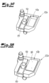
- This rotatable connection is shown in particular from a comparative view with the Fig. 2 clearly.
- the second joint bracket 10 is formed from a first joint bracket element 10a and a second joint bracket element 10b, which are also are rotatably connected to each other via a vertical axis of rotation.
- Both the first fastening part 6 and the second fastening part 7 each have an upper receiving element 11a, 11b and a lower receiving element 12a, 12b, the upper receiving element 11a and the lower receiving element 12a having a first receiving space 13a of the first fastening part 6 and the upper receiving element 11b and the lower receiving element 12b define a second receiving space 13b of the second fastening part 7, in which the joint brackets 9, 10 are arranged in a closed position.
- the receiving elements 11a, 11b, 12a, 12b are intended in particular to mount the joint brackets 9, 10 on the fastening parts 6, 7 so that they can rotate.
- the receiving elements 11a, 12a of the first fastening part and the receiving elements 11b, 12b of the second fastening part 7 are designed to be mirror-symmetrical to one another, with the individual joint brackets 9, 10 being supported in different ways.
- Fig. 2 shows a cross section through the door hinge 3 according to the invention in an isolated representation and with a view of the lower receiving elements 12a, 12b.
- the receiving elements 12a, 12b are designed as separate components and are releasably attached to a corresponding base body 14a, 14b of the corresponding fastening part 6, 7.
- the attachment can also be provided with an adjustment mechanism which enables movement of the second fastening part 7 relative to the first fastening part 6 and accordingly moves the door leaf 2 within the frame 1 in a vertical direction or in a horizontal direction.
- the joint brackets 9, 10 are mounted on the receiving elements 11b, 12b of the second fastening part 7 in an exclusively rotatable manner, while the receiving elements 11a, 12a of the first fastening part 6 provide for longitudinal displaceability of the first joint bracket 9.
- a link guide consisting of a groove 15 and a guide carriage 16 arranged displaceably in the groove is provided, the first joint bracket 9 being rotatably attached to the guide carriage 16.
- Fig. 3a, 3b show an example of the lower receiving element 12a of the first fastening part, from which on the one hand the groove 15 with the guide carriage 16 and on the other hand the receiving formation in the form of the recess 17a is shown in more detail.
- the recess serves to accommodate a fire protection element 18, which is formed from a material that foams under the influence of heat and is preferably flush with a surface 19 adjacent to the receiving space 13a.
- All recesses 17a, 17b are designed in such a way that they are open relative to the receiving spaces 13a, 13b, so that in the event of a fire, the fire protection element 18 can foam up, enter the recesses 17a, 17b into the receiving spaces 13a, 13b and fill them.
- Articulated brackets 9, 10 can be held for as long as possible, so that in interaction with the fire protection strip 5, on the one hand, sufficient sealing is ensured and, on the other hand, the door leaf 1 can be held within the door frame 2 for a long period of time.
- both the fire protection strip 5 and the fire protection element 18 are made of a material that begins to foam at a temperature of approximately 130 ° C, so that the desired effect can occur at an early stage.
Landscapes
- Engineering & Computer Science (AREA)
- Mechanical Engineering (AREA)
- Special Wing (AREA)
Description
Die vorliegende Erfindung betrifft ein Türband mit einem ersten und einem zweiten Befestigungsteil sowie mit zumindest einem Gelenkbügel, der die Befestigungsteile schwenkbeweglich miteinander verbindet, wobei zumindest eines der Befestigungsteile einen Aufnahmeraum bildendes oberes und unteres Aufnahmeelement aufweist, an denen der zumindest eine Gelenkbügel drehbeweglich gelagert ist.The present invention relates to a door hinge with a first and a second fastening part and with at least one joint bracket which connects the fastening parts to one another in a pivotable manner, with at least one of the fastening parts having upper and lower receiving elements which form a receiving space and on which the at least one joint bow is rotatably mounted.
Aus der Praxis ist es bekannt, Türen brandschutzhemmend auszugestalten. Eine solche Brandschutzhemmung betrifft einerseits den Türflügel, welcher entweder aus einem hitzebeständigen Material gebildet ist oder Materialien enthält, welche selbstlöschend wirken und hierzu im Falle einer Hitzeeinwirkung kühlende Materialien wie z. B. Wasser freisetzen, um so über einen längeren Zeitraum einen Durchtritt des Feuers zu verhindern. Besonders bekannt ist in diesem Zusammenhang Gips, welcher beispielsweise innerhalb des Türflügels eingebracht werden kann.It is known from practice to design doors to be fireproof. Such fire protection relates, on the one hand, to the door leaf, which is either made of a heat-resistant material or contains materials that have a self-extinguishing effect and, in the event of heat, cooling materials such as. B. release water to prevent the fire from spreading over a longer period of time. Particularly well-known in this context is plaster, which can be placed inside the door leaf, for example.
Darüber hinaus ist es von besonderem Interesse, auch einen Durchtritt von Gasen zwischen den Türfugen zu verhindern. Bei diesen Gasen kann es sich einerseits um Luftsauerstoff und andererseits um Rauchgase handeln. Während der Eintritt von Luftsauerstoff ein Schüren des Feuers bedeuten würde, kann die Entwicklung von Rauchgas das Durchqueren etwaiger Fluchtwege verhindern. Vor diesem Hintergrund ist es bekannt, an den Schmalseiten des Türflügels oder in der Falz der Türzarge sogenannte Brandschutzelemente in Form von Brandschutzstreifen vorzusehen, welche im Falle einer Hitzeentwicklung aufschäumen und hierdurch den Türspalt zwischen Türflügel und Türzarge abdichten. Im Zuge des Aufschäumens entwickelt sich ein sogenannter Blähdruck, welcher üblicherweise im Rahmen von einem bis 1,5 N/mm2 die Fuge verschließt.In addition, it is of particular interest to prevent gases from passing between the door joints. These gases can be atmospheric oxygen on the one hand and smoke gases on the other. While the entry of atmospheric oxygen would fuel the fire, the development of smoke gas can prevent any escape routes from being passed through. Against this background, it is known to provide so-called fire protection elements in the form of fire protection strips on the narrow sides of the door leaf or in the rebate of the door frame, which foam in the event of heat development and thereby seal the door gap between the door leaf and the door frame. In the course of foaming, a so-called expansion pressure develops, which is usually between one and 1.5 N/mm 2 in the joint closed.
Allerdings setzt ein solcher wirksamer Verschluss zwischen Türflügel und Türzarge voraus, dass der Türflügel auch im Falle einer Hitzeentwicklung möglichst über einen langen Zeitraum mechanisch gehalten wird, so dass auch den Türbändern im besonderen Maße Bedeutung zukommt.However, such an effective closure between the door leaf and the door frame requires that the door leaf is held mechanically over a long period of time, even in the event of heat development, so that the door hinges are also particularly important.
Beispielsweise werden heutzutage eine Vielzahl von Türbändern aus sogenanntem Zinkdruckguss hergestellt, welcher sich zwar in einfacher Art und Weise gestalten lässt, dessen Schmelzpunkt aber bereits mit 650 °C im Falle eines Brandes leicht überschritten werden kann. Infolgedessen schmilzt das Türband zumindest teilweise auf, so dass die erforderliche mechanische Stabilität unter Umständen nicht mehr gewährleistet werden kann.For example, nowadays a large number of door hinges are made from so-called die-cast zinc, which can be designed in a simple manner, but whose melting point can easily be exceeded at 650 °C in the event of a fire. As a result, the door hinge at least partially melts, so that the required mechanical stability can no longer be guaranteed under certain circumstances.
Aufgrund der Vielzahl der Bauteile und insbesondere aufgrund der verschwenkbaren Ausgestaltung bildet das Türband darüber hinaus eine Vielzahl von Fugen, welche einen Durchtritt von Gasen nicht vollständig verhindern können. Vor diesem Hintergrund ist es daher zweckmäßig, auch bei den Türbändern brandschutzhemmende Maßnahmen vorzusehen.Due to the large number of components and in particular due to the pivotable design, the door hinge also forms a large number of joints, which cannot completely prevent the passage of gases. Against this background, it is therefore advisable to also provide fire protection measures for the door hinges.
Der vorliegenden Erfindung liegt daher die Aufgabe zugrunde, ein Türband anzugeben, welches sich gegenüber den bisherigen Lösungen durch eine verbesserte Brandschutzhemmung auszeichnet. Darüber hinaus soll auch der Brandschutz von Türen mit derartigen Türbändern verbessert werden.The present invention is therefore based on the object of providing a door hinge which is characterized by improved fire protection compared to previous solutions. In addition, the fire protection of doors with such door hinges should also be improved.
Diese Aufgabe wird gelöst durch ein Türband gemäß Patentanspruch 1. Dementsprechend weist zumindest eines der Aufnahmeelemente eine in Richtung des Aufnahmeraums offene Aufnahmeausformung auf, in der ein aus einem unter Hitzeeinwirkung aufschäumenden Material gebildetes Brandschutzelement angeordnet ist.This object is achieved by a door hinge according to claim 1. Accordingly, at least one of the receiving elements has a receiving formation that is open in the direction of the receiving space, in which a material formed from a material that foams under the influence of heat Fire protection element is arranged.
Hierbei geht die Erfindung von der Erkenntnis aus, dass die Aufnahmeelemente üblicherweise derart in den Befestigungsteilen gebildet oder angeordnet sind, dass das Einbringen einer Ausnahmeausformung ohne Weiteres möglich ist. Dieser Raum kann dann für ein Brandschutzelement genutzt werden, welches durch die Ausnahmeausformung gehalten und zugleich sichergestellt wird, dass der zumindest eine Gelenkbügel ohne Weiteres über der Ausformung und damit auch über dem Brandschutzmaterial verschwenken können.The invention is based on the knowledge that the receiving elements are usually formed or arranged in the fastening parts in such a way that the introduction of an exceptional shape is easily possible. This space can then be used for a fire protection element, which is held by the exception formation and at the same time ensures that the at least one hinge bracket can easily pivot over the formation and thus also over the fire protection material.
Zugleich kann durch die Bildung eines speziellen Bereiches sichergestellt werden, dass eine ausreichende Menge des aufschäumenden Materials in die Aufnahmeelemente beziehungsweise in das entsprechende Aufnahmeelement eingebracht werden kann, welches dann im Falle einer Hitzeeinwirkung aufschäumt und insbesondere die Aufnahmebereiche der Gelenkbügel ausschäumt. Die Zwischenräume werden dann dicht verschlossen, wodurch einerseits der Durchtritt von Gasen verhindert wird und zugleich die Gelenkbügel auch im Falle eines bereichsweise Aufschmelzens der Türbänder derart gehalten werden, dass der Türflügel innerhalb der Türzarge über einen möglichst langen Zeitraum verbleibt. In Ergänzung mit Brandschutzelementen zwischen Türflügel und Türzarge kann somit eine Tür geschaffen werden, welche über einen möglichst langen Zeitraum einer einseitigen Hitzeeinwirkung standhält und zugleich das Betreten von Fluchtwegen ermöglicht.At the same time, by forming a special area, it can be ensured that a sufficient amount of the foaming material can be introduced into the receiving elements or into the corresponding receiving element, which then foams in the event of heat and in particular foams the receiving areas of the joint brackets. The gaps are then sealed tightly, which on the one hand prevents the passage of gases and at the same time, even in the event of the door hinges melting in some areas, the hinge brackets are held in such a way that the door leaf remains within the door frame for as long as possible. In addition to fire protection elements between the door leaf and door frame, a door can be created that can withstand one-sided heat exposure for as long as possible and at the same time allows access to escape routes.
Besonders vorteilhaft ist eine solche Ausgestaltung selbstverständlich dann, wenn auch der Türflügel aus einem brandschutzhemmenden Material gebildet ist. Aber selbst im Falle eines Türflügels aus Holz kann so eine höhere Brandschutzklasse erreicht werden. Hierbei ist zu beachten, dass sich die Brandschutzklassifikation nicht nach einzelnen Komponenten sondern vielmehr an dem Gesamttürsystem richtet. Je länger der Zeitraum andauert, in dem die Tür dem Brand standhält, desto höher ist auch die Brandschutzklassifikation. Dennoch können selbstverständlich einzelne Komponenten zu einer höheren Brandschutzklassifikation beitragen. Durch die verbesserte Brandschutzhemmung des Türbandes ist daher auch eine höhere Brandschutzklassifikation des gesamten Türsystems möglich.Such a design is of course particularly advantageous if the door leaf is also made of a fire-retardant material. But even in the case of a wooden door, a higher fire protection class can be achieved. It should be noted that the fire protection classification is not based on individual components but rather aimed at the overall door system. The longer the period in which the door withstands fire, the higher the fire protection classification. Nevertheless, individual components can of course contribute to a higher fire protection classification. Due to the improved fire protection of the door hinge, a higher fire protection classification of the entire door system is also possible.
Die Formschlussausformung kann grundsätzlich in unterschiedlicher Art und Weise ausgebildet sein. So reicht es beispielsweise aus, wenn in die der Gelenkbügel zugewandten Oberfläche des entsprechenden Aufnahmeelementes Rippen vorgesehen sind, die dann eine seitliche Begrenzung für das Brandschutzelement bilden. Das Einprägen derartiger Rippen ist insbesondere dann besonders vorteilhaft, wenn die Aufnahmeelemente im Wesentlichen als Umformteile aus Blech gebildet sind und somit eine entsprechend geringe Wandstärke aufweisen.The form-fitting formation can fundamentally be designed in different ways. For example, it is sufficient if ribs are provided in the surface of the corresponding receiving element facing the hinge bracket, which then form a lateral boundary for the fire protection element. The embossing of such ribs is particularly advantageous when the receiving elements are essentially formed as formed parts made of sheet metal and thus have a correspondingly small wall thickness.
Alternativ ist es jedoch gemäß einer bevorzugten Ausgestaltung vorgesehen, dass die Ausnahmeausformung als Vertiefung ausgebildet ist. Eine solche Vertiefung meint im Rahmen der Erfindung einen Rücksprung im Aufnahmeelement ausgehend von einer den Gelenkbügeln zugewandten Oberfläche. Eine solche Ausgestaltung ist insbesondere dann sinnvoll, wenn das Aufnahmeelement nicht als Umformteil sondern beispielsweise als Druckgussteil, z. B. Zinkdruckgussteil ausgebildet ist. Hierdurch kann durch die Vertiefung zusätzlich eine Materialersparnis erzielt werden.Alternatively, however, according to a preferred embodiment, it is provided that the exception formation is designed as a recess. In the context of the invention, such a recess means a recess in the receiving element starting from a surface facing the joint brackets. Such a configuration is particularly useful if the receiving element is not a formed part but, for example, a die-cast part, e.g. B. zinc die-cast part is formed. As a result, additional material savings can be achieved through the depression.
Die Höhe dieser Vertiefung richtet sich insbesondere an der zur Verfügung stehenden Gesamthöhe des Aufnahmeelementes und beträgt gemäß einer bevorzugten Ausgestaltung zwischen 2 und 10 mm, bevorzugt zwischen 3 und 8 mm. Die Grundfläche der Vertiefung kann zwischen 20 und 80 %, bevorzugt zwischen 30 und 70 %, besonders bevorzugt zwischen 40 und 60 % der Oberfläche des jeweiligen Aufnahmeelementes betragen, wobei sich auf eine projizierte Oberfläche des Aufnahmeelementes ohne Einbeziehung von Abschrägungen oder Durchbrechungen bezogen wird. Darüber hinaus liegt es selbstverständlich im Rahmen der Erfindung, dass unterschiedliche Aufnahmeelemente auch unterschiedlich große Vertiefungen aufweisen.The height of this depression depends in particular on the available total height of the receiving element and, according to a preferred embodiment, is between 2 and 10 mm, preferably between 3 and 8 mm. The base area of the depression can be between 20 and 80%, preferably between 30 and 70%, particularly preferably between 40 and 60%, of the surface of the respective receiving element, referring to a projected surface of the receiving element without including bevels or openings. Furthermore, it is of course within the scope of the invention that different receiving elements also have recesses of different sizes.
Im Gegensatz zur Ausbildung mit Rippen hat eine solche Ausgestaltung den Vorteil, dass die Aufnahmeelemente eine im Wesentlichen glatte Oberfläche aufweisen, wodurch die Bewegung der Gelenkbügel in einfacher Art und Weise kontrolliert und ein Schleifen an der Oberfläche des Aufnahmeelementes verhindert werden kann.In contrast to the design with ribs, such a design has the advantage that the receiving elements have a substantially smooth surface, whereby the movement of the joint brackets can be controlled in a simple manner and grinding on the surface of the receiving element can be prevented.
Gemäß einer bevorzugten Weiterbildung der Erfindung ist vorgesehen, dass das Brandschutzelement in einem nicht-aufgeschäumten Zustand bündig an einer an die Vertiefung angrenzenden Fläche des Aufnahmeelementes angrenzt. Es versteht sich, dass es sich bei der angrenzenden Fläche um die Fläche des Aufnahmeelementes handelt, welche den Aufnahmeraum begrenzt. Durch die bündige Ausgestaltung wird sichergestellt, dass der zur Verfügung stehende Raum der Vertiefung bestmöglich ausgenutzt wird, während zugleich durch die bündige Ausgestaltung gewährleistet wird, dass die Gelenkbügel entlang der Oberfläche störungsfrei geführt werden können. Da derartige Ausgestaltungen üblicherweise einer gewissen Fertigungstoleranz unterliegen, ist im Rahmen der Erfindung mit einer bündigen Ausgestaltung gemeint, dass zumindest eine Toleranz von +/- 5 %, bezogen auf die Höhe der Vertiefung, noch immer als bündige Ausbildung verstanden wird.According to a preferred development of the invention, it is provided that the fire protection element, in a non-foamed state, borders flush with a surface of the receiving element adjacent to the recess. It is understood that the adjacent surface is the surface of the receiving element, which delimits the receiving space. The flush design ensures that the available space in the recess is utilized in the best possible way, while at the same time the flush design ensures that the joint brackets can be guided along the surface without interference. Since such designs are usually subject to a certain manufacturing tolerance, in the context of the invention a flush design means that at least a tolerance of +/- 5%, based on the height of the recess, is still understood as a flush design.
Wenngleich es im Rahmen der Erfindung ausreicht, wenn nur eines der Aufnahmeelemente mit einer solchen Aufnahmeausformung und einem darin angeordneten Brandschutzelement ausgebildet ist, so ist gemäß einer bevorzugten Ausgestaltung der Erfindung vorgesehen, dass in dem oberen und dem unteren Aufnahmeelement jeweils eine Aufnahmeausformung und ein in der Aufnahmeausformung angeordnetes Brandschutzelement vorgesehen ist.Although it is sufficient within the scope of the invention if only one of the receiving elements has such a receiving formation and one therein arranged fire protection element is formed, then according to a preferred embodiment of the invention it is provided that a receiving formation and a fire protection element arranged in the receiving formation are provided in the upper and lower receiving elements.
Im Falle eines Brandes schäumen dann alle Brandschutzelemente auf und stabilisieren die Gelenkbügel an allen Aufnahmen, so dass eine größtmögliche mechanische Stabilisierung gewährleistet wird. Zugleich kann durch die mehrfache Anordnung von Brandschutzelementen eine vollständige Ausschäumung der Hohlräume innerhalb des Türbandes wesentlich leichter realisiert werden, als bei einer Ausgestaltung, bei der nur einzelne Aufnahmeelemente mit einer Aufnahmeausformung und einem darin angeordneten Brandschutzelement ausgestattet sind.In the event of a fire, all fire protection elements foam up and stabilize the joint brackets on all mounts, ensuring the greatest possible mechanical stabilization. At the same time, due to the multiple arrangement of fire protection elements, complete foam filling of the cavities within the door hinge can be realized much more easily than in a design in which only individual receiving elements are equipped with a receiving formation and a fire protection element arranged therein.
Als Brandschutzelement kommen insbesondere alle gängigen und aus der Praxis bekannten Materialien in Betracht, wobei bevorzugt vorgesehen ist, dass das in der Aufnahmeausformung angeordnete Brandschutzelement ab einer Temperatur von mehr als 130 °C, besonders bevorzugt ab einer Temperatur von mehr als 150 °C, beginnt aufzuschäumen.In particular, all common materials known from practice can be considered as fire protection elements, with it preferably being provided that the fire protection element arranged in the receiving mold starts at a temperature of more than 130 ° C, particularly preferably at a temperature of more than 150 ° C to foam up.
Bevorzugt sind die Befestigungsteile zumindest teilweise aus einem Zinkdruckguss gebildet. Dies betrifft insbesondere die Grundkörper der Befestigungsteile, in denen dann die Aufnahmeelemente vorzugsweise als separates Bauteil angeordnet sind. Selbstverständlich liegt es auch an der Erfindung, dass die Aufnahmeelemente einstückig mit den Grundkörpern ausgebildet sind, wobei im Falle einer separaten Ausbildung die Aufnahmeelemente ebenfalls als Zinkdruckgussteil hergestellt werden können.The fastening parts are preferably at least partially formed from a zinc die-cast. This applies in particular to the base bodies of the fastening parts, in which the receiving elements are then preferably arranged as a separate component. Of course, it is also due to the invention that the receiving elements are designed in one piece with the base bodies, whereby in the case of a separate design the receiving elements can also be manufactured as a zinc die-cast part.
Wie bereits zuvor erläutert, liegt der besondere Vorteil von Zinkdruckgussteilen darin begründet, dass die Form in einfacher Art und Weise vorgegeben werden kann, so dass eine Vielzahl von Ausgestaltungsformen denkbar sind. Allerdings weisen derartige Zinkdruckgussteile einen im Vergleich zu Edelstahl oder Aluminiumbauteilen geringen Schmelzpunkt auf, so dass derartige Türbänder nur in begrenztem Maße als hitzebeständig bezeichnet werden können. In Kombination mit den erfindungsgemäßen Brandschutzelementen kann aber dennoch ein Türband geschaffen werden, welches sich einerseits durch ein hochwertiges optisches Erscheinungsbild und eine hohe Funktionalität und zugleich durch eine erhöhte Feuerschutzbeständigkeit auszeichnet, da durch die aufschäumenden Brandschutzelemente trotz aufschmelzenden Befestigungsteilen weiterhin eine gewisse mechanische Stabilität und eine ausreichende Gasabdichtung ermöglicht wird.As already explained above, the particular advantage of zinc die-cast parts is The reason is that the shape can be specified in a simple manner, so that a variety of design forms are conceivable. However, such zinc die-cast parts have a low melting point compared to stainless steel or aluminum components, so that such door hinges can only be described as heat-resistant to a limited extent. In combination with the fire protection elements according to the invention, a door hinge can still be created which is characterized on the one hand by a high-quality visual appearance and a high level of functionality and at the same time by increased fire protection resistance, since the foaming fire protection elements continue to provide a certain mechanical stability and sufficient despite melting fasteners Gas sealing is made possible.
Dieser Vorteil kommt vor allem bei Türbändern zur Geltung, welche verdeckt liegend zwischen dem Türflügel und der Türzarge eingesetzt sind. Hierzu sind dann die Befestigungsteile in Ausnehmungen in der Schmalseite des Türflügels und in der Laibungsseite der Türzarge einsetzbar.This advantage is particularly effective with door hinges that are concealed between the door leaf and the door frame. For this purpose, the fastening parts can then be inserted into recesses in the narrow side of the door leaf and in the reveal side of the door frame.
Gemäß einer solchen Ausgestaltung kann vorgesehen sein, dass zumindest ein erster und ein zweiter Gelenkbügel vorgesehen sind, die um eine vertikale Drehachse drehbeweglich miteinander verbunden sind. Ferner kann der erste Gelenkbügel in dem oberen und dem unteren Aufnahmeelement des ersten Befestigungsteils verschiebbar gelagert sein. Dies gilt gleichermaßen für den zweiten Gelenkbügel in dem zweiten Befestigungsteil. Eine solche Ausgestaltung sieht dann üblicherweise Aufnahmeelemente in beiden Befestigungsteilen vor, wobei es grundsätzlich ausreicht, wenn lediglich die Aufnahmeelemente eines Befestigungsteils mit Vertiefungen und Brandschutzelementen ausgebildet sind. Bevorzugt weisen jedoch alle Aufnahmeelemente bzw. das obere und das untere Element beider Befestigungsteile eine entsprechende Aufnahmeausformung auf, so dass dann zumindest vier Brandschutzelemente in dem Türband vorgesehen sind. Die Ausgestaltung der Vertiefung kann sich zwischen den Befestigungsteilen unterscheiden.According to such an embodiment, it can be provided that at least a first and a second joint bracket are provided, which are rotatably connected to one another about a vertical axis of rotation. Furthermore, the first hinge bracket can be slidably mounted in the upper and lower receiving elements of the first fastening part. This applies equally to the second joint bracket in the second fastening part. Such a design then usually provides receiving elements in both fastening parts, although it is generally sufficient if only the receiving elements of one fastening part are designed with recesses and fire protection elements. However, all receiving elements or the upper and lower elements of both fastening parts preferably have a corresponding receiving shape, so that at least four fire protection elements are then provided in the door hinge. The design of the recess can differ between the fastening parts.
Ausgehend von einer Ausgestaltung für eine verdeckte Anordnung des Türbandes sind die Gelenkbügel in einem geschlossenen Zustand in den Aufnahmeräumen der einzelnen Befestigungsteile angeordnet und folglich von außen nicht sichtbar. Eine solche Ausgestaltung kann über unterschiedliche Kinematiken erreicht werden, wobei bevorzugt der erste Gelenkbügel in dem oberen und dem unteren Aufnahmeelement des ersten Befestigungsteils verschiebbar gelagert ist. Hierzu ist der erste Gelenkbügel über eine Kulissenführung in dem oberen und dem unteren Aufnahmeelement des ersten Befestigungsteils drehbar geführt, wobei die Kulissenführung jeweils aus einer in den Befestigungsteilen gebildeten Nut und einem in der Nut verschiebbar angeordneten Führungsschlitten gebildet ist, der über einen Gelenkbolzen mit dem ersten Gelenkbügel verbunden ist.Based on an embodiment for a concealed arrangement of the door hinge, the hinge brackets are arranged in a closed state in the receiving spaces of the individual fastening parts and are therefore not visible from the outside. Such a configuration can be achieved using different kinematics, with the first joint bracket preferably being displaceably mounted in the upper and lower receiving elements of the first fastening part. For this purpose, the first joint bracket is rotatably guided via a link guide in the upper and lower receiving elements of the first fastening part, the link guide each being formed from a groove formed in the fastening parts and a guide carriage which is displaceably arranged in the groove and which is connected to the first one via a hinge pin Joint bracket is connected.
In dem zweiten Befestigungsteil ergibt sich dann eine rein drehbare Anordnung des ersten Gelenkbügels. Der zweite Gelenkbügel kann grundsätzlich analog zu dem ersten Gelenkbügel in den Befestigungsteilen angeordnet sein, wobei dieser dann in dem zweiten Befestigungsteil verschiebbar und drehbeweglich gelagert ist. Gemäß einer bevorzugten Ausgestaltung ist jedoch vorgesehen, dass der zweite Gelenkbügel aus zwei hintereinander drehbeweglich miteinander verbundenen Gelenkbügelteilen verbunden ist, wobei das erste Gelenkbügelteil in dem ersten und das zweite Befestigungsteil in dem zweiten Befestigungsteil drehbeweglich und nicht längsverschieblich gelagert sind.A purely rotatable arrangement of the first joint bracket then results in the second fastening part. The second joint bracket can basically be arranged in the fastening parts in a similar way to the first joint bow, which is then mounted in the second fastening part in a displaceable and rotatable manner. According to a preferred embodiment, however, it is provided that the second joint bracket is connected from two joint bracket parts which are connected one behind the other in a rotationally movable manner, the first joint bracket part being rotatably mounted in the first and the second fastening part in the second fastening part and not being mounted in a longitudinally displaceable manner.
Gemäß einer Weiterbildung der Erfindung sind die Aufnahmeelemente zumindest teilweise lösbar in einem der Befestigungsteile befestigt. Hierdurch ist es insbesondere möglich, die Gelenkbügel zunächst an den Aufnahmeelementen zu befestigen, wobei dann eine Befestigung der Gelenkbügel mit den Aufnahmeelementen in den Grundkörpern der Befestigungsteile erfolgt. Zugleich können auch an den Aufnahmeelementen bzw. an der Verbindung zwischen den Aufnahmeelementen und dem Grundkörper Verstellmechanismen vorgesehen sein, die ein Verstellen der Befestigungsteile zueinander in unterschiedlichen Raumrichtungen ermöglichen. Auch bei einer solchen verstellbaren Ausgestaltung ist die Anordnung der Brandschutzelemente in den Aufnahmeräumen von besonderem Vorteil, da auch im Falle eines Verstellens keine Relativbewegung zwischen den Brandschutzelementen und den Gelenkbügeln erfolgt und somit die Bewegung der Gelenkbügel nicht beeinträchtigt wird.According to a further development of the invention, the receiving elements are at least partially detachably fastened in one of the fastening parts. This is It is particularly possible to first attach the joint brackets to the receiving elements, with the joint brackets then being fastened to the receiving elements in the base bodies of the fastening parts. At the same time, adjustment mechanisms can also be provided on the receiving elements or on the connection between the receiving elements and the base body, which enable the fastening parts to be adjusted relative to one another in different spatial directions. Even with such an adjustable design, the arrangement of the fire protection elements in the receiving spaces is particularly advantageous, since even in the event of adjustment there is no relative movement between the fire protection elements and the joint brackets and thus the movement of the joint brackets is not affected.
Gemäß einer Weiterbildung der Erfindung weist das Türband ausgehend von einer Schließstellung einen Öffnungswinkel von mindestens 135°, bevorzugt von mindestens 160° bis zum Erreichen einer maximalen Öffnungsstellung auf.According to a further development of the invention, the door hinge has an opening angle of at least 135°, preferably of at least 160°, starting from a closed position until a maximum opening position is reached.
Darüber hinaus ist es bevorzugt vorgesehen, dass bei einer Öffnungsbewegung von der Schließstellung zu der Öffnungsstellung die Gelenkbügel sich gegenüber dem ersten Befestigungsteil in eine erste Drehrichtung und das zweite Befestigungsteil gegenüber den Gelenkbügeln ebenfalls in die erste Drehrichtung drehen.In addition, it is preferably provided that during an opening movement from the closed position to the open position, the joint brackets rotate in a first direction of rotation relative to the first fastening part and the second fastening part also rotates in the first direction of rotation relative to the joint brackets.
Gegenstand der Erfindung ist ferner eine Tür mit einem Türflügel, einer Türzarge und zumindest einem erfindungsgemäßen Türband, wobei der Türflügel schwenkbeweglich über das Türband an der Türzarge befestigt ist, wobei das erste Befestigungsteil in einer Ausnehmung in einer Schmalseite des Türflügels und das zweite Befestigungsteil in einer Ausnehmung in der Laibungsseite der Türzarge eingesetzt ist.The invention furthermore relates to a door with a door leaf, a door frame and at least one door hinge according to the invention, the door leaf being pivotably attached to the door frame via the door hinge, the first fastening part in a recess in a narrow side of the door leaf and the second fastening part in one Recess is inserted in the reveal side of the door frame.
Bevorzugt ist vorgesehen, dass die Türzarge eine Falz aufweist, an der der Türflügel in einer Schließstellung anliegt und wobei an einer dem Türflügel zugewandten Seite der Falz ein in vertikaler Richtung verlaufender Brandschutzstreifen aus einem unter Hitzeeinwirkung aufschäumendem Material angeordnet ist. Bei dem Brandschutzstreifen kann es sich um dasselbe Material handeln, welches auch für das Brandschutzelement innerhalb der Türbänder vorgesehen ist. Im Falle einer Brandentwicklung schäumt dann sowohl das Material in dem Türband als auch das Material in der Falz auf und dichtet die Hohlräume zwischen Türflügel und Türzarge ab, wodurch insbesondere ein Durchtritt von Rauchgas und/oder Luftsauerstoff verhindert wird. Darüber hinaus trägt auch das in der Falz angeordnete Material zu einer mechanischen Stabilisierung des Türflügels in der Türzarge bei.It is preferably provided that the door frame has a fold on which the door leaf rests in a closed position and a fire protection strip made of a material that foams under the influence of heat and running in a vertical direction is arranged on a side of the fold facing the door leaf. The fire protection strip can be the same material that is also provided for the fire protection element within the door hinges. In the event of a fire, both the material in the door hinge and the material in the rebate foam and seal the cavities between the door leaf and the door frame, which in particular prevents the passage of smoke gas and/or atmospheric oxygen. In addition, the material arranged in the fold also contributes to mechanical stabilization of the door leaf in the door frame.
Wenngleich grundsätzlich sowohl für das Türblatt als auch für die Türzarge unterschiedliche Materialien je nach gewünschter optischer Erscheinung oder Feuerbeständigkeit in Betracht kommen, so sind das Türblatt und/oder die Türzarge zumindest teilweise aus Holz gebildet.Although in principle different materials can be considered for both the door leaf and the door frame depending on the desired visual appearance or fire resistance, the door leaf and/or the door frame are at least partially made of wood.
Darüber hinaus ist es gemäß einer besonders bevorzugten Ausgestaltung vorgesehen, dass zwei identisch ausgebildete Türbänder in vertikaler Richtung übereinander angeordnet sind. Sofern es sich um einen besonders schweren Türflügel handelt, kann es auch sinnvoll sein, mehr als zwei übereinander angeordnete Türbänder, zum Beispiel drei Türbänder, vorzusehen, da so das Gewicht gleichmäßiger auf die Türzarge übertragen werden kann.In addition, according to a particularly preferred embodiment, it is provided that two identically designed door hinges are arranged one above the other in the vertical direction. If it is a particularly heavy door leaf, it may also make sense to provide more than two door hinges arranged one above the other, for example three door hinges, as this allows the weight to be transferred more evenly to the door frame.
Im Folgenden wird die Erfindung anhand von Ausführungsbeispielen näher erläutert. Es zeigen:
- Fig. 1
- eine Tür mit einem erfindungsgemäßen Türband,
- Fig. 2
- das erfindungsgemäße Türband in einer Schnittdarstellung und
- Fig. 3a, 3b
- Aufnahmeelemente des erfindungsgemäßen Türbandes mit und ohne Brandschutzelement.
- Fig. 1
- a door with a door hinge according to the invention,
- Fig. 2
- the door hinge according to the invention in a sectional view and
- Fig. 3a, 3b
- Receiving elements of the door hinge according to the invention with and without fire protection element.
Die
Das Türband 3 weist ein flügelseitiges, erstes Befestigungsteil 6 und ein zargenseitiges, zweites Befestigungsteil 7 auf, welche in Vertiefungen 8 in der Schmalseite des Türflügels 1 und in der Türzarge 2 eingebracht sind.The
Das Türband 3 weist darüber hinaus einen ersten Gelenkbügel 9 und einen zweiten Gelenkbügel 10 auf, die um eine vertikale Drehachse D drehbeweglich miteinander verbunden sind. Diese drehbewegliche Verbindung wird insbesondere aus einer vergleichenden Ansicht mit der
Sowohl das erste Befestigungsteil 6 als auch das zweite Befestigungsteil 7 weisen jeweils ein oberes Aufnahmeelement 11a, 11b und ein unteres Aufnahmeelement 12a, 12b auf, wobei das obere Aufnahmeelement 11a und das untere Aufnahmeelement 12a einen ersten Aufnahmeraum 13a des ersten Befestigungsteils 6 und das obere Aufnahmeelement 11b und das untere Aufnahmeelement 12b einen zweiten Aufnahmeraum 13b des zweiten Befestigungsteils 7 definieren, in denen die Gelenkbügel 9, 10 in einer Schließstellung angeordnet sind.Both the first fastening part 6 and the second fastening part 7 each have an
Die Aufnahmeelemente 11a, 11b, 12a, 12b sind insbesondere dazu vorgesehen, die Gelenkbügel 9, 10 drehbeweglich an den Befestigungsteilen 6, 7 zu lagern. Hierzu sind die Aufnahmeelemente 11a, 12a des ersten Befestigungsteils und die Aufnahmeelemente 11b, 12b zweiten Befestigungsteils 7 spiegelsymmetrisch zueinander ausgebildet, wobei die Lagerung der einzelnen Gelenkbügel 9, 10 in unterschiedlicher Art und Weise erfolgt. Dies zeigt sich insbesondere deutlich anhand der
Hieraus wird deutlich, dass die Aufnahmeelemente 12a, 12b als separate Bauteile ausgebildet und lösbar an einem entsprechenden Grundkörper 14a, 14b des entsprechenden Befestigungsteils 6, 7 befestigt sind. Die Befestigung kann ferner mit einem Verstellmechanismus versehen sein, der eine Bewegung des zweiten Befestigungsteils 7 relativ zum ersten Befestigungsteil 6 ermöglicht und entsprechend den Türflügel 2 innerhalb der Zarge 1 in vertikaler Richtung oder in eine horizontale Richtung verschiebt.It is clear from this that the receiving elements 12a, 12b are designed as separate components and are releasably attached to a corresponding base body 14a, 14b of the corresponding fastening part 6, 7. The attachment can also be provided with an adjustment mechanism which enables movement of the second fastening part 7 relative to the first fastening part 6 and accordingly moves the
Die Gelenkbügel 9, 10 sind an den Aufnahmeelementen 11b, 12b des zweiten Befestigungsteils 7 ausschließlich drehbeweglich gelagert, während die Aufnahmeelemente 11a, 12a des ersten Befestigungsteils 6 eine Längsverschieblichkeit des ersten Gelenkbügels 9 vorsieht. Hierzu ist eine Kulissenführung bestehend aus einer Nut 15 und einem in der Nut verschiebbar angeordneten Führungsschlitten 16 vorgesehen, wobei der erste Gelenkbügel 9 drehbeweglich an dem Führungsschlitten 16 befestigt ist.The
Da bereits für die Nut 15 eine gewisse vertikale Erstreckung der Aufnahmeelemente 11a, 12a erforderlich ist, ermöglicht es dies darüber hinaus, eine weitere Vertiefung 17a vorzusehen. Eine entsprechende Vertiefung 17a ist dann auch in dem oberen Aufnahmeelement 11a vorgesehen. Bei dieser Vertiefung handelt es sich um eine Aufnahmeausformung, dessen Funktionalität zu einem späteren Zeitpunkt näher erläutert wird.Since a certain vertical extension of the receiving elements 11a, 12a is already required for the
Die
Alle Vertiefungen 17a, 17b sind so ausgestaltet, dass sie gegenüber den Aufnahmeräumen 13a, 13b geöffnet sind, so dass im Falle eines Brandes das Brandschutzelement 18 aufschäumen, aus den Vertiefungen 17a, 17b heraus in die Aufnahmeräume 13a, 13b eintreten und diese ausfüllen kann. Hierdurch wird gewährleistet, dass auch bei Verlust der mechanischen Stabilität der einzelnen Befestigungsteile 6, 7, welche aus einem Zinkdruckguss gebildet sind, die Gelenkbügel 9, 10 über einen möglichst langen Zeitraum gehalten werden können, so dass im Zusammenspiel mit dem Brandschutzstreifen 5 einerseits eine ausreichende Abdichtung gewährleistet und andererseits der Türflügel 1 über einen langen Zeitraum innerhalb der Türzarge 2 gehalten werden kann. Üblicherweise sind sowohl der Brandschutzstreifen 5 als auch das Brandschutzelement 18 aus einem Material gebildet, welches ab einer Temperatur von ca. 130 °C beginnt aufzuschäumen, so dass bereits frühzeitig der gewünschte Effekt eintreten kann.All recesses 17a, 17b are designed in such a way that they are open relative to the receiving spaces 13a, 13b, so that in the event of a fire, the
Claims (15)
- A door hinge (3) comprising a first and a second fastening part (6, 7) as well as comprising at least one joint bracket (9, 10), which connects the fastening parts to one another in a pivotably movable manner, wherein at least one of the fastening parts (6, 7) has an upper and lower receiving element (11a, 11b, 12a, 12b), which forms a receiving space (13a, 13b) and on which the at least one joint bracket (9, 10) is mounted in a rotatably movable manner,
characterized in that
at least one of the receiving elements (11a, 11b, 12a, 12b) has a receiving molding, which is open in the direction of the receiving space (13a, 13b) and in which a fire protection element (18) is arranged, which is made of a material, which foams under the effect of heat. - The door hinge (3) according to claim 1, characterized in that the receiving molding is formed as depression (17a, 17b).
- The door hinge (3) according to claim 2, characterized in that in a non-foamed state, the fire protection element (18) adjoins flush on an area (19) of the receiving element (11a, 11b, 12a, 12b), which adjoins the depression (17a, 17b).
- The door hinge (3) according to one of claims 1 to 3, characterized in that a receiving molding and a fire protection element (18) arranged in the receiving molding is in each case provided in the upper and the lower receiving element (11a, 11b, 12a, 12b).
- The door hinge (3) according to one of claims 1 to 4, characterized in that the fire protection element (18) arranged in the receiving molding foams at a temperature of more than 130°C, preferably more than 150°C.
- The door hinge (3) according to one of claims 1 to 5, characterized in that the fastening parts (6, 7) are at least partially made of a zinc die casting.
- The door hinge (3) according to one of claims 1 to 6, characterized in that the fastening parts (6, 7) can be inserted in recesses (8) in the narrow side of a door leaf (1), and in the soffit side of a door frame (2).
- The door hinge (3) according to one of claims 1 to 7, characterized in that at least a first and a second joint bracket (9, 10) are provided, which are connected to one another in a rotationally movable manner about a vertical axis of rotation (D).
- The door hinge (3) according to claim 8, characterized in that the first joint bracket (9) is displaceably mounted in the upper and the lower receiving element (11a, 12a) of the first fastening part (6).
- The door hinge (3) according to one of claims 1 to 9, characterized in that the receiving elements (11a, 11b, 12a, 12b) are at least partially releasably fastened to a base body (14a, 14b) of the fastening parts (6, 7).
- The door hinge (3) according to one of claims 1 to 10, characterized in that in a closed position, the joint brackets (9, 10) are arranged essentially in receiving spaces (13a, 13b) of the fastening parts (6, 7).
- A door comprising a door leaf (1), a door frame (2) and at least one door hinge (3) according to one of claims 1 to 11, via which door hinge the door leaf (2) is fastened to the door frame (1) in a pivotably movable manner, wherein the first fastening part (6) is inserted in a recess (8) in a narrow side of the door leaf (1), and the second fastening part (7) in a recess (8) in a soffit side of the door frame (2).
- The door according to claim 12, characterized in that the door frame (2) has a rabbet (4), against which the door leaf (1) abuts in a closed position and wherein a fire protection strip (5), which runs in the vertical direction (Z), of a material, which foams under the effect of heat, is arranged on a side of the rabbet (4) facing the door leaf (1).
- The door according to claim 12 or 13, characterized in that the door leaf (1) and/or the door frame (2) are at least partially made of wood.
- The door according to one of claims 12 to 14, characterized in that at least two identically formed door hinges (3) are arranged one on top of the other in the vertical direction (Z).
Applications Claiming Priority (1)
| Application Number | Priority Date | Filing Date | Title |
|---|---|---|---|
| DE102021129869.5A DE102021129869B3 (en) | 2021-11-16 | 2021-11-16 | Door hinge with fire protection element |
Publications (3)
| Publication Number | Publication Date |
|---|---|
| EP4180602A1 EP4180602A1 (en) | 2023-05-17 |
| EP4180602C0 EP4180602C0 (en) | 2024-02-28 |
| EP4180602B1 true EP4180602B1 (en) | 2024-02-28 |
Family
ID=83546724
Family Applications (1)
| Application Number | Title | Priority Date | Filing Date |
|---|---|---|---|
| EP22199232.4A Active EP4180602B1 (en) | 2021-11-16 | 2022-09-30 | Door hinge with fire protection element |
Country Status (3)
| Country | Link |
|---|---|
| US (1) | US20230151658A1 (en) |
| EP (1) | EP4180602B1 (en) |
| DE (1) | DE102021129869B3 (en) |
Families Citing this family (1)
| Publication number | Priority date | Publication date | Assignee | Title |
|---|---|---|---|---|
| EP4185759B1 (en) * | 2020-09-22 | 2024-05-22 | Sfs Intec Ag | Hidden hinge for flush or rebated door or window applications |
Family Cites Families (3)
| Publication number | Priority date | Publication date | Assignee | Title |
|---|---|---|---|---|
| GB2245025B (en) | 1990-05-16 | 1993-11-24 | Jebron Ltd | Hinge |
| GB2275491B (en) | 1993-02-24 | 1996-04-03 | Tools Ltd Nv | Fire door |
| DE202014102793U1 (en) | 2014-06-17 | 2014-06-27 | Simonswerk, Gesellschaft mit beschränkter Haftung | Door leaf-side hinge part of a door hinge and arrangement hereby |
-
2021
- 2021-11-16 DE DE102021129869.5A patent/DE102021129869B3/en active Active
-
2022
- 2022-09-30 EP EP22199232.4A patent/EP4180602B1/en active Active
- 2022-10-21 US US17/971,192 patent/US20230151658A1/en active Pending
Also Published As
| Publication number | Publication date |
|---|---|
| EP4180602C0 (en) | 2024-02-28 |
| DE102021129869B3 (en) | 2023-02-16 |
| EP4180602A1 (en) | 2023-05-17 |
| US20230151658A1 (en) | 2023-05-18 |
Similar Documents
| Publication | Publication Date | Title |
|---|---|---|
| EP3346078B1 (en) | Room door | |
| EP4180602B1 (en) | Door hinge with fire protection element | |
| DE212015000262U1 (en) | With fly screen provided (s), inwardly opening door or window with outwardly opening glass wing and handle set and hinge for it | |
| EP2754841A2 (en) | Fire retardant glazing with wooden door | |
| DE202014102793U1 (en) | Door leaf-side hinge part of a door hinge and arrangement hereby | |
| EP2601369B1 (en) | Fire protection door for railroad car | |
| DE19719113C2 (en) | Door system | |
| DE4318209C2 (en) | Door stop profile for swing doors | |
| CH708369B1 (en) | Fire protection sliding door. | |
| DE2040525A1 (en) | Window or door with wing and frame, in particular made of metal or plastic hollow profiles | |
| AT521183B1 (en) | Wall opening with attached frame and hinged wing and hinge | |
| DE3001070A1 (en) | CORNER JOINT FOR TURN-TIP WINDOWS, DOORS OR THE LIKE | |
| DE2947509A1 (en) | Fire door frame and leaf construction - has leaf with second adjustable sheet with overlap optionally at top or bottom | |
| DE10246513A1 (en) | Covering plate for a wall opening, to give access to an installation, is secured to the edge of the opening by a hinge, with two axes linked together by a hinge bar | |
| DE2022912C3 (en) | Double-leaf fire door | |
| EP3461982B1 (en) | Door assembly | |
| DE3990925C2 (en) | Casement type windows | |
| DE4212902C1 (en) | Window and frame with transom - has transom window suspended by linkage from frame members and forming stop for hinging leaves | |
| DE2519666A1 (en) | Blunt-edged fire screen door - have inside insulation-surrounded frame and outside sheath with perforated spacer strip | |
| DE3039406A1 (en) | Hinging and tilting window opening mechanism - has plates on extension bar with locking faces for blocks | |
| DE202022107195U1 (en) | door frame | |
| EP0113737A4 (en) | Partition element, particularly accordion door panel embodied as a self-carrying box. | |
| DE3032116C2 (en) | ||
| DE202007007569U1 (en) | Sealing arrangement for sealing of base air of door, comprises seal with retractable, automatic sealing strip and sealing is lowered exclusively in closed position of sliding door and at closed door | |
| DE102005013978B3 (en) | Door for mounting cover plates with a clearance between them has a peripheral door leaf and insulation for retaining inserts |
Legal Events
| Date | Code | Title | Description |
|---|---|---|---|
| PUAI | Public reference made under article 153(3) epc to a published international application that has entered the european phase |
Free format text: ORIGINAL CODE: 0009012 |
|
| STAA | Information on the status of an ep patent application or granted ep patent |
Free format text: STATUS: THE APPLICATION HAS BEEN PUBLISHED |
|
| AK | Designated contracting states |
Kind code of ref document: A1 Designated state(s): AL AT BE BG CH CY CZ DE DK EE ES FI FR GB GR HR HU IE IS IT LI LT LU LV MC MK MT NL NO PL PT RO RS SE SI SK SM TR |
|
| STAA | Information on the status of an ep patent application or granted ep patent |
Free format text: STATUS: REQUEST FOR EXAMINATION WAS MADE |
|
| 17P | Request for examination filed |
Effective date: 20230523 |
|
| RBV | Designated contracting states (corrected) |
Designated state(s): AL AT BE BG CH CY CZ DE DK EE ES FI FR GB GR HR HU IE IS IT LI LT LU LV MC MK MT NL NO PL PT RO RS SE SI SK SM TR |
|
| GRAP | Despatch of communication of intention to grant a patent |
Free format text: ORIGINAL CODE: EPIDOSNIGR1 |
|
| STAA | Information on the status of an ep patent application or granted ep patent |
Free format text: STATUS: GRANT OF PATENT IS INTENDED |
|
| RIC1 | Information provided on ipc code assigned before grant |
Ipc: E05D 3/06 20060101ALI20230823BHEP Ipc: E05D 5/02 20060101AFI20230823BHEP |
|
| INTG | Intention to grant announced |
Effective date: 20230927 |
|
| GRAS | Grant fee paid |
Free format text: ORIGINAL CODE: EPIDOSNIGR3 |
|
| GRAA | (expected) grant |
Free format text: ORIGINAL CODE: 0009210 |
|
| STAA | Information on the status of an ep patent application or granted ep patent |
Free format text: STATUS: THE PATENT HAS BEEN GRANTED |
|
| AK | Designated contracting states |
Kind code of ref document: B1 Designated state(s): AL AT BE BG CH CY CZ DE DK EE ES FI FR GB GR HR HU IE IS IT LI LT LU LV MC MK MT NL NO PL PT RO RS SE SI SK SM TR |
|
| REG | Reference to a national code |
Ref country code: GB Ref legal event code: FG4D Free format text: NOT ENGLISH |
|
| REG | Reference to a national code |
Ref country code: CH Ref legal event code: EP |
|
| REG | Reference to a national code |
Ref country code: DE Ref legal event code: R096 Ref document number: 502022000563 Country of ref document: DE |
|
| REG | Reference to a national code |
Ref country code: IE Ref legal event code: FG4D Free format text: LANGUAGE OF EP DOCUMENT: GERMAN |
|
| U01 | Request for unitary effect filed |
Effective date: 20240319 |
|
| U07 | Unitary effect registered |
Designated state(s): AT BE BG DE DK EE FI FR IT LT LU LV MT NL PT SE SI Effective date: 20240326 |