EP4179375B1 - Objektivbaugruppe für ein lichtmodul eines kraftfahrzeugscheinwerfers - Google Patents
Objektivbaugruppe für ein lichtmodul eines kraftfahrzeugscheinwerfers Download PDFInfo
- Publication number
- EP4179375B1 EP4179375B1 EP21743465.3A EP21743465A EP4179375B1 EP 4179375 B1 EP4179375 B1 EP 4179375B1 EP 21743465 A EP21743465 A EP 21743465A EP 4179375 B1 EP4179375 B1 EP 4179375B1
- Authority
- EP
- European Patent Office
- Prior art keywords
- lens
- lens assembly
- shells
- objective lens
- optical axis
- Prior art date
- Legal status (The legal status is an assumption and is not a legal conclusion. Google has not performed a legal analysis and makes no representation as to the accuracy of the status listed.)
- Active
Links
Images



Classifications
-
- F—MECHANICAL ENGINEERING; LIGHTING; HEATING; WEAPONS; BLASTING
- F21—LIGHTING
- F21S—NON-PORTABLE LIGHTING DEVICES; SYSTEMS THEREOF; VEHICLE LIGHTING DEVICES SPECIALLY ADAPTED FOR VEHICLE EXTERIORS
- F21S41/00—Illuminating devices specially adapted for vehicle exteriors, e.g. headlamps
- F21S41/20—Illuminating devices specially adapted for vehicle exteriors, e.g. headlamps characterised by refractors, transparent cover plates, light guides or filters
- F21S41/25—Projection lenses
- F21S41/265—Composite lenses; Lenses with a patch-like shape
-
- F—MECHANICAL ENGINEERING; LIGHTING; HEATING; WEAPONS; BLASTING
- F21—LIGHTING
- F21S—NON-PORTABLE LIGHTING DEVICES; SYSTEMS THEREOF; VEHICLE LIGHTING DEVICES SPECIALLY ADAPTED FOR VEHICLE EXTERIORS
- F21S41/00—Illuminating devices specially adapted for vehicle exteriors, e.g. headlamps
- F21S41/10—Illuminating devices specially adapted for vehicle exteriors, e.g. headlamps characterised by the light source
- F21S41/14—Illuminating devices specially adapted for vehicle exteriors, e.g. headlamps characterised by the light source characterised by the type of light source
- F21S41/141—Light emitting diodes [LED]
- F21S41/143—Light emitting diodes [LED] the main emission direction of the LED being parallel to the optical axis of the illuminating device
-
- F—MECHANICAL ENGINEERING; LIGHTING; HEATING; WEAPONS; BLASTING
- F21—LIGHTING
- F21S—NON-PORTABLE LIGHTING DEVICES; SYSTEMS THEREOF; VEHICLE LIGHTING DEVICES SPECIALLY ADAPTED FOR VEHICLE EXTERIORS
- F21S41/00—Illuminating devices specially adapted for vehicle exteriors, e.g. headlamps
- F21S41/10—Illuminating devices specially adapted for vehicle exteriors, e.g. headlamps characterised by the light source
- F21S41/14—Illuminating devices specially adapted for vehicle exteriors, e.g. headlamps characterised by the light source characterised by the type of light source
- F21S41/141—Light emitting diodes [LED]
- F21S41/151—Light emitting diodes [LED] arranged in one or more lines
-
- F—MECHANICAL ENGINEERING; LIGHTING; HEATING; WEAPONS; BLASTING
- F21—LIGHTING
- F21S—NON-PORTABLE LIGHTING DEVICES; SYSTEMS THEREOF; VEHICLE LIGHTING DEVICES SPECIALLY ADAPTED FOR VEHICLE EXTERIORS
- F21S41/00—Illuminating devices specially adapted for vehicle exteriors, e.g. headlamps
- F21S41/20—Illuminating devices specially adapted for vehicle exteriors, e.g. headlamps characterised by refractors, transparent cover plates, light guides or filters
- F21S41/25—Projection lenses
- F21S41/255—Lenses with a front view of circular or truncated circular outline
-
- F—MECHANICAL ENGINEERING; LIGHTING; HEATING; WEAPONS; BLASTING
- F21—LIGHTING
- F21S—NON-PORTABLE LIGHTING DEVICES; SYSTEMS THEREOF; VEHICLE LIGHTING DEVICES SPECIALLY ADAPTED FOR VEHICLE EXTERIORS
- F21S41/00—Illuminating devices specially adapted for vehicle exteriors, e.g. headlamps
- F21S41/20—Illuminating devices specially adapted for vehicle exteriors, e.g. headlamps characterised by refractors, transparent cover plates, light guides or filters
- F21S41/29—Attachment thereof
- F21S41/295—Attachment thereof specially adapted to projection lenses
-
- F—MECHANICAL ENGINEERING; LIGHTING; HEATING; WEAPONS; BLASTING
- F21—LIGHTING
- F21S—NON-PORTABLE LIGHTING DEVICES; SYSTEMS THEREOF; VEHICLE LIGHTING DEVICES SPECIALLY ADAPTED FOR VEHICLE EXTERIORS
- F21S41/00—Illuminating devices specially adapted for vehicle exteriors, e.g. headlamps
- F21S41/60—Illuminating devices specially adapted for vehicle exteriors, e.g. headlamps characterised by a variable light distribution
- F21S41/65—Illuminating devices specially adapted for vehicle exteriors, e.g. headlamps characterised by a variable light distribution by acting on light sources
- F21S41/663—Illuminating devices specially adapted for vehicle exteriors, e.g. headlamps characterised by a variable light distribution by acting on light sources by switching light sources
-
- G—PHYSICS
- G02—OPTICS
- G02B—OPTICAL ELEMENTS, SYSTEMS OR APPARATUS
- G02B7/00—Mountings, adjusting means, or light-tight connections, for optical elements
- G02B7/02—Mountings, adjusting means, or light-tight connections, for optical elements for lenses
- G02B7/021—Mountings, adjusting means, or light-tight connections, for optical elements for lenses for more than one lens
-
- G—PHYSICS
- G02—OPTICS
- G02B—OPTICAL ELEMENTS, SYSTEMS OR APPARATUS
- G02B7/00—Mountings, adjusting means, or light-tight connections, for optical elements
- G02B7/02—Mountings, adjusting means, or light-tight connections, for optical elements for lenses
- G02B7/022—Mountings, adjusting means, or light-tight connections, for optical elements for lenses lens and mount having complementary engagement means, e.g. screw/thread
-
- G—PHYSICS
- G02—OPTICS
- G02B—OPTICAL ELEMENTS, SYSTEMS OR APPARATUS
- G02B19/00—Condensers, e.g. light collectors or similar non-imaging optics
- G02B19/0033—Condensers, e.g. light collectors or similar non-imaging optics characterised by the use
- G02B19/0047—Condensers, e.g. light collectors or similar non-imaging optics characterised by the use for use with a light source
- G02B19/0061—Condensers, e.g. light collectors or similar non-imaging optics characterised by the use for use with a light source the light source comprising a LED
- G02B19/0066—Condensers, e.g. light collectors or similar non-imaging optics characterised by the use for use with a light source the light source comprising a LED in the form of an LED array
Definitions
- the present invention relates to a lens assembly for a light module of a motor vehicle headlight according to the preamble of claim 1.
- a lens assembly is known from DE 10 2014 216 127 A1 known.
- the known lens assembly has a first lens, a first half-shell and a second half-shell.
- the two half-shells each have a first section and a second section.
- the first sections are designed to encompass an edge of the first lens.
- the first lens has a first optical axis that runs inside the half-shells between the first section and the second section.
- the known lens assembly has a single projection lens as the objective.
- the sections represent ends of the lens assembly in a direction parallel to the optical axis.
- a light source is arranged at the second end of the known lens assembly.
- the object of the present invention is to provide a lens assembly for a high-resolution light module of a motor vehicle headlight, which has several lenses that are positioned and fixed relative to one another precisely and with high temperature stability.
- the lens assembly should be characterized by a small number of components, a low tolerance chain and simple assembly. Furthermore, no additional parts should be required to avoid sun load and stray light.
- sun load refers to the effect of sunlight, which under unfavorable conditions can lead to locally undesirable or even component-endangering high temperatures in the light module due to the focusing effect of optical components of the light module.
- the invention differs from the prior art mentioned at the outset in that the lens assembly has a second lens which has an optical axis coinciding with the first optical axis, that the second sections are designed to encompass an edge of the second lens, that the first half-shell has two first contact surface areas and the second half-shell has two second contact surfaces, wherein the contact surfaces each extend continuously from the first section to the second section, so that one of the first contact surfaces in each case continuously rests against one of the second contact surfaces from the first section to the second section, and that the two half-shells, when joined together, form a tube which is closed at its first section by a lens and which surrounds a part of the optical axis running between the two lenses.
- the sharpness with which the inner light distribution, which is formed by the lens assembly as an outer light distribution of the motor vehicle headlight, can be increased.
- high-resolution internal light distributions such as those that can be generated using micro-LEDs or micro-mirror chips (DMD, digital mirror device)
- DMD micro-mirror chips
- the second lens can be precisely located and held firmly in the light module. Because the first half-shell has two first contact surfaces and the second half-shell has two second contact surfaces, wherein the contact surfaces each extend continuously from the first section to the second section, so that one of the first contact surfaces rests continuously on one of the second contact surfaces from the first section to the second section, the two lenses are precisely held relative to one another. Because the two half-shells, when joined together, form a tube which is closed at its first section by a lens and which surrounds a part of the optical axis running between the two lenses, the beam path of the useful light propagating inside the lens assembly is not impaired by external influences from sunlight or by internal stray light.
- the two half shells also have projections that protrude radially outwards and retaining springs arranged in the circumferential direction, which grip behind the projections in an elastically deformed state and generate clamping forces that act in the circumferential directions of the half shells that are perpendicular to the optical axis and press the contact surfaces that are in contact with one another.
- This enables easy pre-assembly of the lens assembly.
- the lens assembly with the lenses inserted can then be handled as a whole without any problems during further assembly of the light module.
- the elastic bracing ensures good vibration resistance, as the bracing allows small relative movements of the two half shells against one another on the one hand and, on the other hand, ensures a stable connection of the half shells and lenses even when vibrations are applied thanks to play-compensating restoring forces.
- a preferred embodiment is characterized in that the first sections are designed to encompass the edge of the first lens in such a way that the position of the first lens is positively fixed in both directions of its optical axis. As a result, the first lens is held in the lens assembly with little assembly effort, a small number of components and low tolerances.
- the second sections are designed to encompass the edge of the second lens in such a way that the position of the second lens in the is positively fixed in both directions of its optical axis. This means that the second lens is held in the lens assembly with little assembly effort, a small number of components and low tolerances.
- the contact surfaces with which the two half-shells rest against each other lie in a plane in which the optical axis also runs.
- the optical axis usually runs in a plane in which a diameter of the first lens and the second lens also lies. The lenses can therefore be inserted into one of the two half-shells without stress when assembling the lens assembly.
- a further preferred embodiment is characterized in that the arrangement of the two half-shells relative to one another is defined by interlocking form-fitting structures that are arranged in the contact surfaces and protrude from the contact surfaces and/or are recesses such as blind holes.
- At least the first lens has a circular cross-section in a surface perpendicular to its optical axis.
- a further preferred embodiment is characterized in that the light module has a lens carrier which has a circular opening and which surrounds the first ends in an axial direction in a form-fitting and radially force-fitting manner.
- the half-shells are made of liquid crystal polymer.
- Liquid crystal polymer has the advantage of high dimensional stability even with large temperature fluctuations (e.g. -20°C to 100°C).
- the low thermal expansion and high dimensional stability of the half-shells result in a stable position of the lenses in the lens assembly. This is particularly advantageous in connection with the generation of high-resolution internal light distributions.
- the half-shells have inner walls which are provided with anti-scattering light structures.
- a further preferred embodiment is characterized in that the anti-scattered light structures are formed into the inner wall.
- the Figure 1 a motor vehicle headlight 10 with a housing 12, the light exit opening of which is covered by a transparent cover 14 is covered.
- a light module 16 of the motor vehicle headlight 10 is arranged inside the housing 12.
- the light module 16 has a light source 18 and a lens assembly 20.
- the z-direction is a main radiation direction of the light module.
- the x-direction is vertical when the motor vehicle headlight is used as intended.
- the y-direction is horizontal when the motor vehicle headlight is used as intended.
- the light source 18 is designed to generate an internal light distribution.
- the light source 18 consists, for example, of an arrangement 22 of individually and/or group-controlled micro-LEDs 22'.
- the light distribution (which is high-resolution, corresponding to a large number of micro-LEDs) then results, for example, on the light exit surface of the arrangement 22, which in this case is simultaneously a light exit surface of the light source 18.
- the resolution is limited by the size of the light exit surface of an individual micro-LED 22'.
- the light source 18 can also be an arrangement of a bright semiconductor light source and a micromirror arrangement (DMD: digital mirror device) with individually or group-adjustable micromirrors.
- DMD digital mirror device
- the lens assembly 20 is designed to project the inner light distribution as an outer light distribution into the half-space lying in front of the motor vehicle headlight 10 in the z direction.
- the lens assembly has, for example, a cylindrical, in particular a circular cylindrical basic shape.
- the cylinder axis lies, for example, in the z direction, and the guide curve of the cylindrical basic shape is a closed loop that lies, for example, in the x-z plane.
- the lens assembly 20 has a first lens 24, a first half-shell 26 and a second half-shell 28. When joined together, the two half-shells 26, 28 form a tube that has the basic shape mentioned.
- the first lens 24 is a light exit lens of the lens assembly 20.
- Each of the two half-shells 26, 28 has a first section and a second section.
- the first half-shell 26 has a first section 26.1 and a second section 26.2.
- the second half-shell 28 has a first section 28.1 and a second section 28.2.
- the first sections 26.1, 28.1 are each designed to positively engage an edge 24.1 of the first lens 24 in such a way that the position of the first lens is positively fixed in both directions of its optical axis. This allows the first lens to be assembled with little effort, a small number of components and little Tolerances in the lens assembly are maintained.
- the form fit extends over the entire circumference of the lens edge, which lies in a surface that is perpendicular to the optical axis.
- the form fit extends over individual sections of the lens edge.
- the lens edges are, for example, implemented as collars that run around the optically relevant central parts of the lenses.
- the sections have a groove that, in terms of shape and dimensions, forms a negative to the collar, which then represents a positive. This preferably applies to all lenses arranged in the lens assembly.
- the number of sections is preferably three in order to achieve automatic centering of the lens in the sections.
- the sections are preferably arranged equidistantly over the circumference.
- the second sections 26.2, 28.2 are designed to positively engage an edge 30.1 of the second lens 30 such that the position of the second lens is positively fixed in both directions of its optical axis. This also holds the second lens in the lens assembly with little assembly effort, a small number of components and low tolerances.
- the form fit also extends over the entire circumference of the lens edge, the in a surface that is perpendicular to the optical axis.
- the form fit extends over individual sections of the lens edge.
- the number of sections is preferably three in order to achieve automatic centering of the lens in the sections.
- the sections are preferably arranged equidistantly around the circumference.
- the edges 24.1 and 30.1 preferably run in surfaces that are parallel to the x-y plane.
- the first lens 24 has a first optical axis 24.2 that runs inside the half-shells 26, 28 between the first sections 26.1, 28.1 and the second sections 26.2, 28.2.
- the first optical axis 24.2 coincides, for example, with the z-direction.
- the second lens 30 preferably has an optical axis that coincides with the first optical axis 24.2.
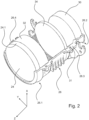
- Figure 2 shows an embodiment of a first half-shell 24 in an oblique view together with a first lens 24, a second lens 30, a third lens 32 and a fourth lens 34.
- the third lens 32 and the fourth lens 34 are only optionally present.
- Figure 3 shows a complementary second half-shell 28.
- the first half-shell 26 has two first contact surfaces 26.3, 26.4, and the second half-shell 28 has two second contact surfaces 28.3, 28.4.
- the second contact surface 28.4 is also shown in the Figure 1 as an edge visible.
- the contact surfaces each extend continuously at least from the first section 26.1 to the second section 26.2, so that one of the first contact surfaces 26.3, 26.4 rests continuously on one of the second contact surfaces 28.3, 28.4 from the first section 26.1 to the second section 26.2.
- the contact surfaces 26.4 and 28.4 extend continuously at least from the first section 26.1 to the second section 26.2, so that the first contact surface 26.4 continuously rests against the second contact surface 28.4 from the first section 26.1 to the second section.
- the arrangement of the two half-shells 26, 28 relative to one another is defined by interlocking form-fitting structures that are arranged in the contact surfaces 26.3, 26.4, 28.3, 28.4.
- the form-fitting structures are preferably elevations 29 (e.g. dowel pins) in one half-shell, which are negatives to depressions 31 in the other half-shell.
- the half shells 26, 28 are made of liquid crystal polymer.
- Figure 3 shows, the inner walls of the half-shells 26, 28 are provided with anti-scattering light structures 33.
- the anti-scattering light structures 33 are grooves (corrugations) formed in the inner walls.
- the scattering structures can be coated in a black or have such a coating.
- the ribs that hold the lenses in the mount can be made higher to cover the edge of a lens and thus reduce stray light (this could be implemented on the light entry side of the lens).
- additional ribs can be added, which then implement the function of an aperture in the finished lens.
- the ribs are clearly visible.
- the ribs are also of different heights.
- Figure 4 shows the objects of Figures 2 and 3 in a state when joined together to form a lens assembly.
- the two half-shells 26, 28 form a tube with a first section and a second section, which is closed at its first section 26.1 by the first lens 24 and which surrounds a part of the optical axis 24.2 running between the two lenses 24, 30.
- the second lens 30 closes off the tube at its second section 26.2.
- the first section preferably forms a first tube end.
- the second section preferably forms a second tube end.
- the tube preferably has a circular-cylindrical basic shape with the optical axis as the cylinder axis.
- the contact surfaces lie in a longitudinal section through this basic shape, in which the cylinder axis also runs.
- the cylinder axis coincides with the optical axis 24.1.
- the tube When assembled, the tube preferably has only the openings designed to accommodate the first lens and the second lens. As a result, the beam path of the useful light propagating inside the lens assembly is not affected by external influences such as scattered light from the environment and/or sunlight.
- the contact surfaces with which the two half-shells rest against each other lie in a plane in which the optical axis 24.2 also runs.
- the optical axis 24.2 usually runs transversely to a plane in which a diameter of the first lens or the second lens also lies.
- the lenses can therefore be inserted into one of the two half-shells without stress when assembling the lens assembly.
- the two half-shells 26, 28 have projections that protrude radially outwards and retaining springs 35 arranged in the circumferential direction, which engage behind the projections in an elastically deformed state and thereby generate tension forces acting in the peripheries of the half-shells that are perpendicular to the optical axis 24.2 and press the contact surfaces that lie against one another.
- the retaining springs 35 are preferably leaf springs made of spring steel with inwardly bent ends 36, the shape of which is adapted to the projections in such a way that they can engage behind them in an elastically deformed state.
- the projections are in the Figure 4 through the mounted Leaf springs 35 covered.
- At least the first lens 24 has a circular cross-section in a surface perpendicular to its optical axis.
- the lens carrier 38 has a circular opening and surrounds the first ends in a form-fitting and/or force-fitting manner.
- the half shells have radially projecting lugs 40 (transverse to the optical axis 24.2) with which they can be screwed together with the lens carrier 38.
- the Figure 4 shown screws 42, the orientation of which represents their screwing direction. The assembly thus formed from lens carrier 38 and lens assembly 20 is adjusted in its position relative to the light source in the light module.
- the shape of the lenses and thus of the closed loop mentioned above does not necessarily have to be circular. It is important that the shape of the half-shells partially corresponds to the shape of the lens edges and thus determines a precisely defined position of the lenses in the lens assembly. The position is pre-fixed in the defined position by preferably two fixing elements such as retaining springs 35. The lens assembly thus formed is then assembled with the lens carrier 38. This permanently strengthens the spring-loaded cohesion of the two half-shells and thus of the entire lens package arranged in the two half-shells.
Landscapes
- Engineering & Computer Science (AREA)
- General Engineering & Computer Science (AREA)
- Physics & Mathematics (AREA)
- Optics & Photonics (AREA)
- Microelectronics & Electronic Packaging (AREA)
- General Physics & Mathematics (AREA)
- Non-Portable Lighting Devices Or Systems Thereof (AREA)
- Lens Barrels (AREA)
Description
- Die vorliegende Erfindung betrifft eine Objektivbaugruppe für ein Lichtmodul eines Kraftfahrzeugscheinwerfers nach dem Oberbegriff des Anspruchs 1. Eine Objektivbaugruppe ist aus der
DE 10 2014 216 127 A1 bekannt. Die bekannte Objektivbaugruppe weist eine erste Linse, eine erste Halbschale und eine zweite Halbschale auf. Die beiden Halbschalen weisen jeweils einen ersten Abschnitt und einen zweiten Abschnitt auf. Die ersten Abschnitte sind dazu eingerichtet, einen Rand der ersten Linse zu umgreifen. Die erste Linse weist eine erste optische Achse auf, die im Inneren der Halbschalen zwischen dem ersten Abschnitt und dem zweiten Abschnitt verläuft. - Die bekannte Objektivbaugruppe weist eine einzelne Projektionslinse als Objektiv auf. Die Abschnitte stellen bei der bekannten Objektivbaugruppe Enden der Objektivbaugruppe in einer zur optischen Achse parallelen Richtung dar. Am zweiten Ende der bekannten Objektivbaugruppe ist eine Lichtquelle angeordnet.
- Aus der
US 2006/023175 A1 ,US 6 172 822 B1 und derUS 4 187 534 A ist jeweils eine Objektivbaugruppe mit den Merkmalen des Oberbegriffs bekannt. - Die Aufgabe der vorliegenden Erfindung besteht darin, eine Objektivbaugruppe für ein hochauflösendes Lichtmodul eines Kraftfahrzeugscheinwerfers anzugeben, die mehrere Linsen aufweist, die relativ zueinander präzise und mit hoher Temperaturstabilität positioniert und fixiert sind. Die Objektivbaugruppe soll sich durch eine geringe Zahl von Bauteilen, eine geringe Toleranzkette und eine einfache Montage auszeichnen. Weiter sollen keine Zusatzteile zur Vermeidung von Sunload und Streulicht erforderlich sein. Der Begriff der Sunload bezeichnet die Wirkung von Sonneneinstrahlung, die bei ungünstigen Verhältnissen durch die fokussierende Wirkung von optischen Komponenten des Lichtmoduls zu lokal unerwünscht oder sogar bauteilgefährdend hohen Temperaturen im Lichtmodul führen kann. Es gibt verschiedene Ursachen innerhalb einer Linse, die zu Streulicht führen und die dann die Lichtverteilung beeinflussen, indem beispielsweise bei einem Teilfernlicht Streulicht in Bereiche der Lichtverteilung gelangt, die dunkel sein sollten. Eine mögliche Quelle von Streulicht sind die Linsenränder, an denen die realen Flächen oft stärker von der Sollfläche abweichen als in der Mitte einer Linse.
- Diese Aufgabe wird mit der Summe der Merkmale des Anspruchs 1 gelöst. Die Erfindung unterscheidet sich von dem eingangs genannten Stand der Technik dadurch, dass die Objektivbaugruppe eine zweite Linse aufweist, die eine mit der ersten optischen Achse zusammenfallende optische Achse aufweist, dass die zweiten Abschnitte dazu eingerichtet sind, einen Rand der zweiten Linse zu umgreifen, dass die erste Halbschale zwei erste Anlageflächenflächen aufweist und die zweite Halbschale zwei zweite Anlageflächen aufweist, wobei sich die Anlageflächen jeweils durchgehend vom ersten Abschnitt zum zweiten Abschnitt erstrecken, so dass jeweils eine der ersten Anlageflächen an einer der zweiten Anlageflächen vom ersten Abschnitt bis zum zweiten Abschnitt durchgehend anliegt, und dass die beiden Halbschalen im zusammengefügten Zustand ein Rohr ergeben, das an seinem ersten Abschnitt durch eine Linse verschlossen ist und das einen zwischen den beiden Linsen verlaufenden Teil der optischen Achse umgibt.
- Durch die Verwendung der zweiten Linse in der Objektivbaugruppe lässt sich die Schärfe, mit der die innere Lichtverteilung, die durch die Objektivbaugruppe als eine äußere Lichtverteilung des Kraftfahrzeugscheinwerfers abgebildet wird, verbessern. Dadurch können auch hochauflösende innere Lichtverteilungen, wie sie mit Mikro-Leuchtdioden oder Mikrospiegelchips (DMD, digital mirror device) erzeugbar sind, unter Beibehaltung ihrer Auflösung als äußere Lichtverteilung des vom Lichtmodul, bzw. des Kraftfahrzeugscheinwerfers abstrahlbaren Lichtes abgebildet werden.
- Dadurch, dass die zweiten Abschnitte dazu eingerichtet sind, einen Rand der zweiten Linse zu umgreifen, kann die zweite Linse präzise lokalisiert und fest im Lichtmodul gehalten werden. Dadurch, dass die erste Halbschale zwei erste Anlageflächenflächen aufweist und die zweite Halbschale zwei zweite Anlageflächen aufweist, wobei sich die Anlageflächen jeweils durchgehend vom ersten Abschnitt zum zweiten Abschnitt erstrecken, so dass jeweils eine der ersten Anlageflächen an einer der zweiten Anlageflächen vom ersten Abschnitt bis zum zweiten Abschnitt durchgehend anliegt, ergibt sich eine präzise Halterung der beiden Linsen relativ zueinander. Dadurch, dass die beiden Halbschalen im zusammengefügten Zustand ein Rohr ergeben, das an seinem ersten Abschnitt durch eine Linse verschlossen ist und das einen zwischen den beiden Linsen verlaufenden Teil der optischen Achse umgibt, wird der Strahlengang des im Inneren der Objektivbaugruppe propagierenden Nutzlichts nicht durch von außen einwirkende Einflüsse von Sonnenlicht oder durch inneres Streulicht beeinträchtigt.
- Ferner wissen die beiden Halbschalen radial nach außen herausragende Vorsprünge und in Umfangsrichtung angeordnete Haltefedern auf, welche die Vorsprünge in einem elastisch verformten Zustand hintergreifen und dabei in den zur optischen Achse senkrechten Umfangsrichtungen der Halbschalen wirkende und die aneinander anliegenden Anlageflächen aufeinanderdrückende Spannkräfte erzeugen. Dadurch wird eine einfache Vormontage der Objektivbaugruppe ermöglicht. Die Objektivbaugruppe mit den eingesetzten Linsen kann dann beim weiteren Zusammenbau des Lichtmoduls problemlos als Ganzes gehandhabt werden. Im späteren Betrieb bewirkt die elastische Verspannung eine gute Vibrationsfestigkeit, da die Verspannung einerseits geringe Relativbewegungen der beiden Halbschalen gegeneinander erlaubt und andererseits durch spielausgleichende Rückstellkräfte für eine auch bei einwirkenden Vibrationen stabile Verbindung der Halbschalen und Linsen sorgt.
- Eine bevorzugte Ausgestaltung zeichnet sich dadurch aus, dass die ersten Abschnitte dazu eingerichtet sind, den Rand der ersten Linse so zu umgreifen, dass die Position der ersten Linse in den beiden Richtungen ihrer optischen Achse formschlüssig fixiert ist. Dadurch wird die erste Linse mit geringem Montageaufwand, geringer Bauteilezahl und geringen Toleranzen in der Objektivbaugruppe gehalten.
- Bevorzugt ist auch, dass die zweiten Abschnitte dazu eingerichtet sind, den Rand der zweiten Linse so zu umgreifen, dass die Position der zweiten Linse in den beiden Richtungen ihrer optischen Achse formschlüssig fixiert ist. Dadurch wird die zweite Linse mit geringem Montageaufwand, geringer Bauteilezahl und geringen Toleranzen in der Objektivbaugruppe gehalten.
- Weiter ist bevorzugt, dass die Anlageflächen, mit denen die beiden Halbschalen aneinander anliegen, in einer Ebene liegen, in der auch die optische Achse verläuft. Die optische Achse verläuft in der Regel in einer Ebene, in der auch ein Durchmesser der ersten Linse und der zweiten Linse liegt. Die Linsen können dadurch bei der Montage der Objektivbaugruppe spannungsfrei in eine der beiden Halbschalen eingelegt werden.
- Eine weitere bevorzugte Ausgestaltung zeichnet sich dadurch aus, dass die Anordnung der beiden Halbschalen relativ zueinander durch ineinandergreifende Formschlussstrukturen definiert wird, die in den Anlageflächen angeordnet sind und aus den Anlageflächen herausragen und/oder Vertiefungen wie zum Beispiel Sacklöcher sind. Dadurch wird die Lage der Halbschalen zueinander und damit auch die Lage der ersten Linse und der zweiten Linse zueinander präzise festgelegt, was für die Qualität der durch die Objektivbaugruppe vermittelten optischen Abbildung vorteilhaft ist.
- Weiter ist bevorzugt, dass wenigstens die erste Linse in einer zu ihrer optischen Achse senkrechten Fläche einen kreisrunden Querschnitt aufweist.
- Eine weitere bevorzugte Ausgestaltung zeichnet sich dadurch aus, dass das Lichtmodul einen Objektivträger aufweist, der eine kreisrunde Öffnung aufweist und der die ersten Enden in einer axialen Richtung formschlüssig und radial kraftschlüssig umgreift.
- Bevorzugt ist auch, dass die Halbschalen aus Flüssigkristallpolymer bestehen. Flüssigkristallpolymer hat den Vorteil einer hohen Formtreue auch bei großen Temperaturschwankungen (z.B. -20°C bis 100°C). Durch die geringe Wärmeausdehnung und die hohe Formbeständigkeit der Halbschalen ergibt sich eine stabile Position der Linsen in der Objektiv-Baugruppe. Dies ist insbesondere in Verbindung mit der Erzeugung hochaufgelöster innerer Lichtverteilungen von Vorteil. Je temperaturstabiler die Linsenpositionen sind, desto kleiner fallen durch Temperaturänderungen der Objektivbaugruppe bedingte Verzerrungen der äußeren Lichtverteilung aus, die sich durch die mittels der Objektivbaugruppe erfolgende Abbildung der inneren Lichtverteilung ergibt.
- Weiter ist bevorzugt, dass die Halbschalen Innenwände aufweisen, welche mit Antistreulichtstrukturen versehen sind.
- Eine weitere bevorzugte Ausgestaltung zeichnet sich dadurch aus, dass die Antistreulichtstrukturen in die Innenwand eingeformt sind.
- Weitere Vorteile ergeben sich aus der nachfolgenden Beschreibung, den Zeichnungen und den Unteransprüchen. Es versteht sich, dass die vorstehend genannten und die nachstehend noch zu erläuternden Merkmale nicht nur in der jeweils angegebenen Kombination, sondern auch in anderen Kombinationen oder in Alleinstellung verwendbar sind
- Ausführungsbeispiele der Erfindung sind in den Zeichnungen dargestellt und werden in der nachfolgenden Beschreibung näher erläutert.
- Dabei zeigen, jeweils in schematischer Form:
- Figur 1
- ein Ausführungsbeispiel eines erfindungsgemäßen Kraftfahrzeugscheinwerfers;
- Figur 2
- ein Ausführungsbeispiel einer ersten Halbschale;
- Figur 3
- ein Ausführungsbeispiel einer zweiten Halbschale; und
- Figur 4
- die Gegenstände der
Figuren 2 und3 in einem zu einer Objektivbaugruppe zusammengefügten Zustand. - Im Einzelnen zeigt die
Figur 1 einen Kraftfahrzeugscheinwerfer 10 mit einem Gehäuse 12, dessen Lichtaustrittsöffnung durch eine transparente Abdeckscheibe 14 abgedeckt wird. Im Inneren des Gehäuses 12 ist ein Lichtmodul 16 des Kraftfahrzeugscheinwerfers 10 angeordnet. Das Lichtmodul 16 weist eine Lichtquelle 18 und eine Objektivbaugruppe 20 auf. Die z-Richtung ist eine Hauptabstrahlrichtung des Lichtmoduls. Die x-Richtung ist bei bestimmungsgemäßer Verwendung des Kraftfahrzeugscheinwerfers vertikal. Die y-Richtung ist bei bestimmungsgemäßer Verwendung des Kraftfahrzeugscheinwerfers horizontal. - Die Lichtquelle 18 ist dazu eingerichtet, eine innere Lichtverteilung zu erzeugen. Die Lichtquelle 18 besteht zum Beispiel aus einer Anordnung 22 von individuell und/oder gruppenweise steuerbaren Mikro-Leuchtdioden 22'. Die (entsprechend einer hohen Zahl von Mikro-Leuchtdioden hochaufgelöste) Lichtverteilung ergibt sich dann zum Beispiel auf der Lichtaustrittsfläche der Anordnung 22, die in diesem Fall gleichzeitig eine Lichtaustrittsfläche der Lichtquelle 18 ist. Die Auflösung wird durch die Größe der Lichtaustrittsfläche einer einzelnen Mikro-Leuchtdiode 22' begrenzt. Alternativ kann die Lichtquelle 18 auch eine Anordnung aus einer lichtstarken Halbleiterlichtquelle und einer Mikrospiegelanordnung (DMD: digital mirror device) mit individuell oder gruppenweise verstellbaren Mikrospiegeln sein. Dabei werden die Mikrospiegel von der Halbleiterlichtquelle beleuchtet, und diese reflektieren das Licht je nach Spiegelstellung in die Objektivbaugruppe oder in andere Richtungen.
- Die Objektivbaugruppe 20 ist dazu eingerichtet, die innere Lichtverteilung als äußere Lichtverteilung in den in z-Richtung vor dem Kraftfahrzeugscheinwerfer 10 liegenden Halbraum zu projizieren. Die Objektivbaugruppe besitzt zum Beispiel eine zylindrische, insbesondere eine kreiszylindrische Grundform. Dabei liegt die Zylinderachse zum Beispiel in der z-Richtung, und die Leitkurve der zylindrischen Grundform ist eine geschlossene Schleife, die zum Beispiel in der x-z-Ebene liegt.
- Die Objektivbaugruppe 20 weist eine erste Linse 24, eine erste Halbschale 26 und eine zweite Halbschale 28 auf. Im zusammengefügten Zustand bilden die beiden Halbschalen 26, 28 ein Rohr, das die genannte Grundform aufweist. Die erste Linse 24 ist eine Lichtaustrittslinse der Objektivbaugruppe 20.
- Jede der beiden Halbschalen 26, 28 weist jeweils einen ersten Abschnitt und einen zweiten Abschnitt auf. Die erste Halbschale 26 weist einen ersten Abschnitt 26.1 und einen zweiten Abschnitt 26.2 auf. Analog weist die zweite Halbschale 28 einen ersten Abschnitt 28.1 und einen zweiten Abschnitt 28.2 auf.
- Die ersten Abschnitte 26.1, 28.1 sind jeweils dazu eingerichtet, einen Rand 24.1 der ersten Linse 24 formschlüssig so zu umgreifen, dass die Position der ersten Linse in den beiden Richtungen ihrer optischen Achse formschlüssig fixiert ist. Dadurch wird die erste Linse mit geringem Montageaufwand, geringer Bauteilezahl und geringen Toleranzen in der Objektivbaugruppe gehalten.
- Der Formschluss erstreckt sich in einer Ausgestaltung über den ganzen Umfang des Linsenrandes, der in einer quer zur optischen Achse liegenden Fläche liegt. Alternativ dazu erstreckt sich der Formschluss über einzelne Teilabschnitte des Linsenrandes. Die Linsenränder sind zum Beispiel als um die optisch relevanten zentralen Teile der Linsen herumlaufende Kragen realisiert. Die Abschnitte weisen eine Hohlkehle auf, die nach Form und Abmessungen ein Negativ zu dem dann ein Positiv darstellenden Kragen bildet. Dies gilt bevorzugt für sämtliche in der Objektivbaugruppe angeordneten Linsen. Die Zahl der Teilabschnitte ist bevorzugt gleich drei, um eine automatische Zentrierung der Linse in den Teilabschnitten zu erzielen. Die Teilabschnitte sind bevorzugt äquidistant über den Umfang verteilt angeordnet
- Analog dazu sind die zweiten Abschnitte 26.2, 28.2 dazu eingerichtet, einen Rand 30.1 der zweiten Linse 30 formschlüssig so zu umgreifen, dass die Position der zweiten Linse in den beiden Richtungen ihrer optischen Achse formschlüssig fixiert ist. Dadurch wird auch die zweite Linse mit geringem Montageaufwand, geringer Bauteilezahl und geringen Toleranzen in der Objektivbaugruppe gehalten.
- Der Formschluss erstreckt sich auch hier in einer Ausgestaltung über den ganzen Umfang des Linsenrandes, der in einer quer zur optischen Achse liegenden Fläche liegt. Alternativ dazu erstreckt sich der Formschluss über einzelne Teilabschnitte des Linsenrandes. Die Zahl der Teilabschnitte ist bevorzugt gleich drei, um eine automatische Zentrierung der Linse in den Teilabschnitten zu erzielen. Die Teilabschnitte sind bevorzugt äquidistant über den Umfang verteilt angeordnet.
- Die Ränder 24.1 und 30.1 verlaufen bevorzugt in Flächen, die parallel zur x-y-Ebene liegen. Die erste Linse 24 weist eine erste optische Achse 24.2 auf, die im Inneren der Halbschalen 26, 28 zwischen den ersten Abschnitten 26.1, 28. 1 und den zweiten Abschnitten 26.2, 28.2 verläuft. Die erste optische Achse 24.2 fällt zum Beispiel mit der z-Richtung zusammen. Die zweite Linse 30 weist bevorzugt eine mit der ersten optischen Achse 24.2 zusammenfallende optische Achse auf.
-
Figur 2 zeigt ein Ausführungsbeispiel einer ersten Halbschale 24 in Schrägansicht zusammen mit einer ersten Linse 24, einer zweiten Linse 30, einer dritten Linse 32 und einer vierten Linse 34. Die dritte Linse 32 und die vierte Linse 34 sind nur optional vorhanden. -
Figur 3 zeigt eine dazu komplementäre zweite Halbschale 28. Die erste Halbschale 26 weist zwei erste Anlageflächen 26.3, 26.4 auf, und die zweite Halbschale 28 weist zwei zweite Anlageflächen 28.3, 28.4 auf. Die zweite Anlagefläche 28.4 ist auch in derFigur 1 als Kante sichtbar. - Die Anlageflächen erstrecken sich jeweils durchgehend wenigstens vom ersten Abschnitt 26.1 zum zweiten Abschnitt 26.2, so dass jeweils eine der ersten Anlageflächen 26.3, 26.4 an einer der zweiten Anlageflächen 28.3, 28.4 vom ersten Abschnitt 26.1 bis zum zweiten Abschnitt 26.2 durchgehend anliegt.
- Zum Beispiel erstrecken sich die Anlageflächen 26.4 und 28.4 durchgehend wenigstens vom ersten Abschnitt 26.1 zum zweiten Abschnitt 26.2, so dass die erste Anlagefläche 26.4 an der zweiten Anlagefläche 28.4 vom ersten Abschnitt 26.1 bis zum zweiten Abschnitt durchgehend anliegt.
- Die Anordnung der beiden Halbschalen 26, 28 relativ zueinander wird durch ineinandergreifende Formschlussstrukturen definiert, die in den Anlageflächen 26.3, 26.4, 28.3, 28.4 angeordnet sind. Die Formschlussstrukturen sind bevorzugt Erhebungen 29 (z.B. Passstifte) in der jeweils einen Halbschale, die Negative zu Vertiefungen 31 in der jeweils anderen Halbschale sind.
- Die Halbschalen 26, 28 bestehen aus Flüssigkristallpolymer. Wie
Figur 3 zeigt, sind Innenwände der Halbschalen 26, 28 mit Antistreulichtstrukturen 33 versehen. In einer Ausgestaltung sind die Antistreulichtstrukturen 33 in die Innenwände eingeformte Rillen (Riffelung). Alternativ können die Streustrukturen in einer schwarzen Beschichtung bestehen oder eine solche Beschichtung aufweisen. - Bei der vorliegenden Erfindung können die Rippen, die die Linsen in der Fassung halten, höher werden um den Rand einer Linse abzudecken und so Streulicht zu reduzieren (das könnte auf der Lichteintrittsseite des Objektivs realisiert sein). Ebenso können zusätzliche Rippen eingefügt werden, die dann im fertigen Objektiv die Funktion einer Blende realisieren. In
Figur 3 sind die Rippen gut zu erkennen. In einer bevorzugten Ausgestaltung sind die Rippen auch unterschiedlich hoch. -
Figur 4 zeigt die Gegenstände derFiguren 2 und3 in einem zu einer Objektivbaugruppe zusammengefügten Zustand. In diesem Zustand ergeben die beiden Halbschalen 26, 28 ein Rohr mit einem ersten Abschnitt und einem zweiten Abschnitt, das an seinem ersten Abschnitt 26.1 durch die erste Linse 24 verschlossen ist und das einen zwischen den beiden Linsen 24, 30 verlaufenden Teil der optischen Achse 24.2 umgibt. Die zweite Linse 30 schließt das Rohr an seinem zweiten Abschnitt 26.2 ab. Der erste Abschnitt bildet bevorzugt ein erstes Rohrende. Der zweite Abschnitt bildet bevorzugt ein zweites Rohrende. Das Rohr hat bevorzugt eine kreiszylindrische Grundform mit der optischen Achse als Zylinderachse. Die Anlageflächen liegen in einem Längsschnitt durch diese Grundform, in dem auch die Zylinderachse verläuft. Die Zylinderachse fällt mit der optischen Achse 24.1 zusammen. - Das Rohr weist im zusammengefügten Zustand bevorzugt nur die zur Aufnahme der ersten Linse und der zweiten Linse eingerichteten Öffnungen auf. Dadurch wird der Strahlengang des im Inneren der Objektivbaugruppe propagierenden Nutzlichts nicht durch von außen einwirkende Einflüsse von Streulicht aus der Umgebung und/oder Sonnenlicht beeinträchtigt.
- Die Anlageflächen, mit denen die beiden Halbschalen aneinander anliegen, liegen in einer Ebene, in der auch die optische Achse 24.2 verläuft. Die optische Achse 24.2 verläuft in der Regel quer zu einer Ebene, in der auch ein Durchmesser der ersten Linse oder der zweiten Linse liegt. Die Linsen können dadurch bei der Montage der Objektivbaugruppe spannungsfrei in eine der beiden Halbschalen eingelegt werden
Die beiden Halbschalen 26, 28 weisen radial nach außen herausragende Vorsprünge und in Umfangsrichtung angeordnete Haltefedern 35 auf, welche die Vorsprünge in einem elastisch verformten Zustand hintergreifen und dabei in den zur optischen Achse 24.2 senkrechten Umfängen der Halbschalen wirkende und die aneinander anliegenden Anlageflächen aufeinanderdrückende Spannkräfte erzeugen. Die Haltefedern 35 sind bevorzugt Blattfedern aus Federstahl mit einwärts gebogenen Enden 36, die in ihrer Form so an die Vorsprünge angepasst sind, dass sie diese in einem elastisch verformten Zustand hintergreifen können. Die Vorsprünge sind in derFigur 4 durch die montierten Blattfedern 35 verdeckt. - Wenigstens die erste Linse 24 weist in einer zu ihrer optischen Achse senkrechten Fläche einen kreisrunden Querschnitt auf.
- Der Objektivträger 38 weist eine kreisrunde Öffnung auf und umgreift die ersten Enden formschlüssig und/oder kraftschlüssig. Die Halbschalen weisen radial (quer zur optischen Achse 24.2) abstehende Laschen 40 auf, mit denen sie gemeinsam mit dem Objektivträger 38 verschraubbar sind. Dazu dienen die in der
Figur 4 dargestellten Schrauben 42, deren Ausrichtung ihre Einschraubrichtung darstellt. Die so gebildete Baugruppe aus Objektivträger 38 und Objektivbaugruppe 20 wird im Lichtmodul in seiner Lage relativ zu der Lichtquelle eingestellt. - Die Form der Linsen und damit der weiter oben genannten geschlossenen Schleife muss nicht zwangsläufig kreisförmig sein. Wesentlich ist, dass die Form der Halbschalen partiell der Form der Linsenränder entspricht und damit eine präzise definierte Lage der Linsen in der Objektivbaugruppe festlegt. Die Lage wird durch bevorzugt zwei Fixierelemente wie Haltefedern 35 in der definierten Lage vorfixiert. Anschließend wird die so gebildete Objektivbaugruppe mit dem Objektivträger 38 zusammengebaut. Dadurch wird der federnde Zusammenhalt der beiden Halbschalen und damit des gesamten in den beiden Halbschalen angeordneten Linsenpaketes dauerhaft verstärkt.
Claims (10)
- Objektivbaugruppe (20) für ein Lichtmodul (12) eines Kraftfahrzeugscheinwerfers (10), wobei die Objektivbaugruppe (20) eine erste Linse (24), eine erste Halbschale (26) und eine zweite Halbschale (28) aufweist, wobei die beiden Halbschalen (26, 28) jeweils einen ersten Abschnitt (26.1, 28.1) und einen zweiten Abschnitt (26.2, 28.2) aufweisen, die ersten Abschnitte (26.1, 28.1) dazu eingerichtet sind, einen Rand (24.1) der ersten Linse (24) zu umgreifen, und wobei die erste Linse (24.1) eine erste optische Achse (24.2) aufweist, die im Inneren der Halbschalen (26, 28) zwischen dem ersten Abschnitt (26.1, 28.1) und dem zweiten Abschnitt (26.2, 28.2) verläuft, wobei die Objektivbaugruppe (20) eine zweite Linse (30) aufweist, die eine mit der ersten optischen Achse (24.1) zusammenfallende optische Achse aufweist, dass die zweiten Abschnitte (26.2, 28.2) dazu eingerichtet sind, einen Rand (30.1) der zweiten Linse (30) zu umgreifen, dass die erste Halbschale (26) zwei erste Anlageflächen (26.3, 26.4) aufweist und die zweite Halbschale (28) zwei zweite Anlageflächen (28.3, 28.4) aufweist, wobei sich die Anlageflächen (26.3, 26.4, 28.3, 28.4) jeweils durchgehend vom ersten Abschnitt (26.1, 28.1) zum zweiten Abschnitt (26.2, 28.2) erstrecken, so dass jeweils eine der ersten Anlageflächen (26.3, 26.4) an einer der zweiten Anlageflächen (28.3, 28.4) vom ersten Abschnitt (26.1, 28.1) bis zum zweiten Abschnitt (26.2, 28.2) durchgehend anliegt, und dass die beiden Halbschalen (26, 28) im zusammengefügten Zustand ein Rohr ergeben, das an seinem ersten Abschnitt (26.1, 28.1) durch eine Linse (24) verschlossen ist und das einen zwischen den beiden Linsen (24, 30) verlaufenden Teil der optischen Achse (24.1) umgibt, dadurch gekennzeichnet, dass die beiden Halbschalen (26, 28) radial nach außen herausragende Vorsprünge und Haltefedern (35) aufweisen, welche die Vorsprünge in einem elastisch verformten Zustand hintergreifen und dabei in den zur optischen Achse (24.1) senkrechten Umfangsrichtungen der Halbschalen (26, 28) wirkende und die aneinander anliegenden Anlageflächen aufeinanderdrückende Spannkräfte erzeugen.
- Objektivbaugruppe (20) nach Anspruch 1, dadurch gekennzeichnet, dass die ersten Abschnitte (26.1, 28.1) dazu eingerichtet sind, den Rand der ersten Linse (24) so zu umgreifen, dass die Position der ersten Linse (24) in den beiden Richtungen ihrer optischen Achse (24.1) formschlüssig fixiert ist.
- Objektivbaugruppe (20) nach Anspruch 1 oder 2, dadurch gekennzeichnet, dass die zweiten Abschnitte (26.2, 28.2) dazu eingerichtet sind, den Rand der zweiten Linse so zu umgreifen, dass die Position der zweiten Linse (30) in den beiden Richtungen ihrer optischen Achse formschlüssig fixiert ist.
- Objektivbaugruppe (20) nach einem der vorhergehenden Ansprüche, dadurch gekennzeichnet, dass die Anlageflächen (26.3, 26.4, 28.3, 28.4), mit denen die beiden Halbschalen (26, 28) aneinander anliegen, in einer Ebene liegen, in der auch die optische Achse (24.1) verläuft.
- Objektivbaugruppe (20) nach einem der vorhergehenden Ansprüche, dadurch gekennzeichnet, dass die Anordnung der beiden Halbschalen (26, 28) relativ zueinander durch ineinandergreifende Formschlussstrukturen (29, 31) definiert wird, die in den Anlageflächen angeordnet sind.
- Objektivbaugruppe (20) nach einem der vorhergehenden Ansprüche, dadurch gekennzeichnet, dass wenigstens die erste Linse (24) in einer zu ihrer optischen Achse (24.1) senkrechten Fläche einen kreisrunden Querschnitt aufweist.
- Objektivbaugruppe (20) nach Anspruch 6, dadurch gekennzeichnet, dass sie einen Objektivträger (38) aufweist, der eine Öffnung aufweist und der die ersten Enden in einer axialen Richtung formschlüssig und radial kraftschlüssig umgreift.
- Objektivbaugruppe (20) nach einem der vorhergehenden Ansprüche, dadurch gekennzeichnet, dass die Halbschalen (26, 28) aus Flüssigkristallpolymer bestehen.
- Objektivbaugruppe (20) nach einem der vorhergehenden Ansprüche dadurch gekennzeichnet, dass die Halbschalen Innenwände aufweisen, welche mit Antistreulichtstrukturen (33) versehen sind.
- Objektivbaugruppe (20) nach Anspruch 7, dadurch gekennzeichnet, dass die Antistreulichtstrukturen (33) in eine Innenwand eingeformt sind.
Applications Claiming Priority (2)
| Application Number | Priority Date | Filing Date | Title |
|---|---|---|---|
| DE102020118455.7A DE102020118455A1 (de) | 2020-07-13 | 2020-07-13 | Objektivbaugruppe für ein Lichtmodul eines Kraftfahrzeugscheinwerfers |
| PCT/EP2021/069332 WO2022013150A1 (de) | 2020-07-13 | 2021-07-12 | Objektivbaugruppe für ein lichtmodul eines kraftfahrzeugscheinwerfers |
Publications (2)
| Publication Number | Publication Date |
|---|---|
| EP4179375A1 EP4179375A1 (de) | 2023-05-17 |
| EP4179375B1 true EP4179375B1 (de) | 2024-12-25 |
Family
ID=76999859
Family Applications (1)
| Application Number | Title | Priority Date | Filing Date |
|---|---|---|---|
| EP21743465.3A Active EP4179375B1 (de) | 2020-07-13 | 2021-07-12 | Objektivbaugruppe für ein lichtmodul eines kraftfahrzeugscheinwerfers |
Country Status (4)
| Country | Link |
|---|---|
| EP (1) | EP4179375B1 (de) |
| CN (1) | CN115917389A (de) |
| DE (1) | DE102020118455A1 (de) |
| WO (1) | WO2022013150A1 (de) |
Family Cites Families (8)
| Publication number | Priority date | Publication date | Assignee | Title |
|---|---|---|---|---|
| US4187534A (en) * | 1976-11-08 | 1980-02-05 | Berkey-Colortran, Inc. | Universal lens mounting for selective spotlight beam spread |
| US6172822B1 (en) * | 1998-02-25 | 2001-01-09 | High End Systems, Inc. | Lens holder |
| JP2005243590A (ja) | 2004-01-29 | 2005-09-08 | Ichikoh Ind Ltd | プロジェクタ型車両用灯具 |
| US7277243B2 (en) * | 2004-07-27 | 2007-10-02 | Infocus Corporation | Lens assembly with integrated features |
| JP2008204903A (ja) * | 2007-02-22 | 2008-09-04 | Ichikoh Ind Ltd | 車両用前照灯の灯具ユニット |
| DE102014216127A1 (de) | 2014-08-13 | 2016-02-18 | Automotive Lighting Reutlingen Gmbh | Projektionslichtmodul für einen Kraftfahrzeugscheinwerfermit einem zentralen Linsenträger |
| JP6556530B2 (ja) | 2015-07-02 | 2019-08-07 | 株式会社小糸製作所 | 車両用灯具 |
| DE102018112386A1 (de) | 2018-05-23 | 2019-11-28 | Automotive Lighting Reutlingen Gmbh | Lichtmodul mit einer Glasvorsatzoptik und einem Halter |
-
2020
- 2020-07-13 DE DE102020118455.7A patent/DE102020118455A1/de not_active Ceased
-
2021
- 2021-07-12 WO PCT/EP2021/069332 patent/WO2022013150A1/de not_active Ceased
- 2021-07-12 CN CN202180044510.7A patent/CN115917389A/zh active Pending
- 2021-07-12 EP EP21743465.3A patent/EP4179375B1/de active Active
Also Published As
| Publication number | Publication date |
|---|---|
| DE102020118455A1 (de) | 2022-01-13 |
| WO2022013150A1 (de) | 2022-01-20 |
| CN115917389A (zh) | 2023-04-04 |
| EP4179375A1 (de) | 2023-05-17 |
Similar Documents
| Publication | Publication Date | Title |
|---|---|---|
| DE3516812C2 (de) | ||
| DE102013102819A1 (de) | Kameramodul sowie Verfahren zur Herstellung | |
| WO2022207302A1 (de) | Linsenhalteanordnung | |
| EP4179375B1 (de) | Objektivbaugruppe für ein lichtmodul eines kraftfahrzeugscheinwerfers | |
| DE102017117468B3 (de) | Vorrichtung zur variierbaren Beeinflussung der Wellenfront eines Strahlenbündels mit einer über ihre Umfangsfläche deformierbaren Planoptik | |
| EP4140822B1 (de) | Sensorverbausystem für ein fahrzeug | |
| EP3765883B1 (de) | Justierfassung zur radialen justierung einer optischen einheit mit einer optischen achse | |
| DE102011052793B4 (de) | Optikträger | |
| DE102019217713A1 (de) | Kameraobjektivanordnung | |
| EP3961088A1 (de) | Kraftfahrzeugscheinwerfer | |
| WO2019224110A1 (de) | Lichtmodul mit einer glasvorsatzoptik und einem halter | |
| DE102020211663A1 (de) | Optisches System, insbesondere Lithographiesystem | |
| WO2020182533A1 (de) | Haltevorrichtung eines lichtmoduls einer leuchteinheit, lichtmodul und leuchteinheit eines fahrzeugs | |
| DE102021107413B3 (de) | Kompakte Justierfassung zur Justierung von zwei optischen Tuben | |
| EP0590439B1 (de) | Scheinwerfer für Fahrzeuge | |
| DE102012200736A1 (de) | Spiegelanordnung, insbesondere zum Einsatz in einer mikrolithographischen Projektionsbelichtungsanlage | |
| DE102017209286B3 (de) | Kameramodul für ein Fahrzeug, Kamerasystem und Verfahren zum Herstellen eines Kameramoduls | |
| DE102006041428A1 (de) | Projektionssystem für eine Kraftfahrzeugleuchte | |
| DE102022117917A1 (de) | Projektoranordnung und projektionssystem | |
| EP1762774A1 (de) | Scheinwerfer | |
| DE102021130506A1 (de) | Lichtmodul für einen Kraftfahrzeugscheinwerfer und Befestigung von Bauteilen des Lichtmoduls | |
| DE102009056659A1 (de) | Objektiv für eine Halbleiterkamera und Verfahren zum Fokussieren einer Halbleiterkamera | |
| DE102022116003A1 (de) | Verfahren zum Herstellen einer Kamera-Unterbaugruppe, Kamera-Unterbaugruppe und Kraftfahrzeugkamera | |
| EP3942225B1 (de) | Projektionsvorrichtung für einen kraftfahrzeugscheinwerfer | |
| DE102018209526A1 (de) | Projektionsbelichtungsanlage mit einer Anordnung zur Halterung von optischen Elementen mit zusätzlicher Torsionsentkopplung |
Legal Events
| Date | Code | Title | Description |
|---|---|---|---|
| STAA | Information on the status of an ep patent application or granted ep patent |
Free format text: STATUS: UNKNOWN |
|
| STAA | Information on the status of an ep patent application or granted ep patent |
Free format text: STATUS: THE INTERNATIONAL PUBLICATION HAS BEEN MADE |
|
| PUAI | Public reference made under article 153(3) epc to a published international application that has entered the european phase |
Free format text: ORIGINAL CODE: 0009012 |
|
| STAA | Information on the status of an ep patent application or granted ep patent |
Free format text: STATUS: REQUEST FOR EXAMINATION WAS MADE |
|
| 17P | Request for examination filed |
Effective date: 20230125 |
|
| AK | Designated contracting states |
Kind code of ref document: A1 Designated state(s): AL AT BE BG CH CY CZ DE DK EE ES FI FR GB GR HR HU IE IS IT LI LT LU LV MC MK MT NL NO PL PT RO RS SE SI SK SM TR |
|
| DAV | Request for validation of the european patent (deleted) | ||
| DAX | Request for extension of the european patent (deleted) | ||
| GRAP | Despatch of communication of intention to grant a patent |
Free format text: ORIGINAL CODE: EPIDOSNIGR1 |
|
| STAA | Information on the status of an ep patent application or granted ep patent |
Free format text: STATUS: GRANT OF PATENT IS INTENDED |
|
| RIC1 | Information provided on ipc code assigned before grant |
Ipc: F21S 41/29 20180101ALI20240715BHEP Ipc: F21S 41/663 20180101ALI20240715BHEP Ipc: F21S 41/265 20180101ALI20240715BHEP Ipc: F21S 41/151 20180101ALI20240715BHEP Ipc: F21S 41/143 20180101ALI20240715BHEP Ipc: G02B 19/00 20060101ALI20240715BHEP Ipc: F21S 41/255 20180101ALI20240715BHEP Ipc: G02B 7/02 20210101AFI20240715BHEP |
|
| INTG | Intention to grant announced |
Effective date: 20240731 |
|
| GRAS | Grant fee paid |
Free format text: ORIGINAL CODE: EPIDOSNIGR3 |
|
| GRAA | (expected) grant |
Free format text: ORIGINAL CODE: 0009210 |
|
| STAA | Information on the status of an ep patent application or granted ep patent |
Free format text: STATUS: THE PATENT HAS BEEN GRANTED |
|
| AK | Designated contracting states |
Kind code of ref document: B1 Designated state(s): AL AT BE BG CH CY CZ DE DK EE ES FI FR GB GR HR HU IE IS IT LI LT LU LV MC MK MT NL NO PL PT RO RS SE SI SK SM TR |
|
| RAP3 | Party data changed (applicant data changed or rights of an application transferred) |
Owner name: MARELLI GERMANY GMBH |
|
| REG | Reference to a national code |
Ref country code: GB Ref legal event code: FG4D Free format text: NOT ENGLISH |
|
| REG | Reference to a national code |
Ref country code: CH Ref legal event code: EP |
|
| P01 | Opt-out of the competence of the unified patent court (upc) registered |
Free format text: CASE NUMBER: APP_62931/2024 Effective date: 20241127 |
|
| REG | Reference to a national code |
Ref country code: DE Ref legal event code: R096 Ref document number: 502021006218 Country of ref document: DE |
|
| REG | Reference to a national code |
Ref country code: IE Ref legal event code: FG4D Free format text: LANGUAGE OF EP DOCUMENT: GERMAN |
|
| REG | Reference to a national code |
Ref country code: LT Ref legal event code: MG9D |
|
| PG25 | Lapsed in a contracting state [announced via postgrant information from national office to epo] |
Ref country code: HR Free format text: LAPSE BECAUSE OF FAILURE TO SUBMIT A TRANSLATION OF THE DESCRIPTION OR TO PAY THE FEE WITHIN THE PRESCRIBED TIME-LIMIT Effective date: 20241225 |
|
| PG25 | Lapsed in a contracting state [announced via postgrant information from national office to epo] |
Ref country code: FI Free format text: LAPSE BECAUSE OF FAILURE TO SUBMIT A TRANSLATION OF THE DESCRIPTION OR TO PAY THE FEE WITHIN THE PRESCRIBED TIME-LIMIT Effective date: 20241225 |
|
| PG25 | Lapsed in a contracting state [announced via postgrant information from national office to epo] |
Ref country code: BG Free format text: LAPSE BECAUSE OF FAILURE TO SUBMIT A TRANSLATION OF THE DESCRIPTION OR TO PAY THE FEE WITHIN THE PRESCRIBED TIME-LIMIT Effective date: 20241225 |
|
| PG25 | Lapsed in a contracting state [announced via postgrant information from national office to epo] |
Ref country code: NO Free format text: LAPSE BECAUSE OF FAILURE TO SUBMIT A TRANSLATION OF THE DESCRIPTION OR TO PAY THE FEE WITHIN THE PRESCRIBED TIME-LIMIT Effective date: 20250325 |
|
| PG25 | Lapsed in a contracting state [announced via postgrant information from national office to epo] |
Ref country code: GR Free format text: LAPSE BECAUSE OF FAILURE TO SUBMIT A TRANSLATION OF THE DESCRIPTION OR TO PAY THE FEE WITHIN THE PRESCRIBED TIME-LIMIT Effective date: 20250326 Ref country code: LV Free format text: LAPSE BECAUSE OF FAILURE TO SUBMIT A TRANSLATION OF THE DESCRIPTION OR TO PAY THE FEE WITHIN THE PRESCRIBED TIME-LIMIT Effective date: 20241225 |
|
| PG25 | Lapsed in a contracting state [announced via postgrant information from national office to epo] |
Ref country code: RS Free format text: LAPSE BECAUSE OF FAILURE TO SUBMIT A TRANSLATION OF THE DESCRIPTION OR TO PAY THE FEE WITHIN THE PRESCRIBED TIME-LIMIT Effective date: 20250325 |
|
| REG | Reference to a national code |
Ref country code: NL Ref legal event code: MP Effective date: 20241225 |
|
| PG25 | Lapsed in a contracting state [announced via postgrant information from national office to epo] |
Ref country code: NL Free format text: LAPSE BECAUSE OF FAILURE TO SUBMIT A TRANSLATION OF THE DESCRIPTION OR TO PAY THE FEE WITHIN THE PRESCRIBED TIME-LIMIT Effective date: 20241225 |
|
| PG25 | Lapsed in a contracting state [announced via postgrant information from national office to epo] |
Ref country code: SM Free format text: LAPSE BECAUSE OF FAILURE TO SUBMIT A TRANSLATION OF THE DESCRIPTION OR TO PAY THE FEE WITHIN THE PRESCRIBED TIME-LIMIT Effective date: 20241225 |
|
| PG25 | Lapsed in a contracting state [announced via postgrant information from national office to epo] |
Ref country code: PL Free format text: LAPSE BECAUSE OF FAILURE TO SUBMIT A TRANSLATION OF THE DESCRIPTION OR TO PAY THE FEE WITHIN THE PRESCRIBED TIME-LIMIT Effective date: 20241225 |
|
| PG25 | Lapsed in a contracting state [announced via postgrant information from national office to epo] |
Ref country code: ES Free format text: LAPSE BECAUSE OF FAILURE TO SUBMIT A TRANSLATION OF THE DESCRIPTION OR TO PAY THE FEE WITHIN THE PRESCRIBED TIME-LIMIT Effective date: 20241225 |
|
| PG25 | Lapsed in a contracting state [announced via postgrant information from national office to epo] |
Ref country code: IS Free format text: LAPSE BECAUSE OF FAILURE TO SUBMIT A TRANSLATION OF THE DESCRIPTION OR TO PAY THE FEE WITHIN THE PRESCRIBED TIME-LIMIT Effective date: 20250425 |
|
| PG25 | Lapsed in a contracting state [announced via postgrant information from national office to epo] |
Ref country code: PT Free format text: LAPSE BECAUSE OF FAILURE TO SUBMIT A TRANSLATION OF THE DESCRIPTION OR TO PAY THE FEE WITHIN THE PRESCRIBED TIME-LIMIT Effective date: 20250428 |
|
| PG25 | Lapsed in a contracting state [announced via postgrant information from national office to epo] |
Ref country code: EE Free format text: LAPSE BECAUSE OF FAILURE TO SUBMIT A TRANSLATION OF THE DESCRIPTION OR TO PAY THE FEE WITHIN THE PRESCRIBED TIME-LIMIT Effective date: 20241225 |
|
| PGFP | Annual fee paid to national office [announced via postgrant information from national office to epo] |
Ref country code: FR Payment date: 20250620 Year of fee payment: 5 |
|
| PG25 | Lapsed in a contracting state [announced via postgrant information from national office to epo] |
Ref country code: RO Free format text: LAPSE BECAUSE OF FAILURE TO SUBMIT A TRANSLATION OF THE DESCRIPTION OR TO PAY THE FEE WITHIN THE PRESCRIBED TIME-LIMIT Effective date: 20241225 |
|
| PG25 | Lapsed in a contracting state [announced via postgrant information from national office to epo] |
Ref country code: SK Free format text: LAPSE BECAUSE OF FAILURE TO SUBMIT A TRANSLATION OF THE DESCRIPTION OR TO PAY THE FEE WITHIN THE PRESCRIBED TIME-LIMIT Effective date: 20241225 |
|
| PG25 | Lapsed in a contracting state [announced via postgrant information from national office to epo] |
Ref country code: CZ Free format text: LAPSE BECAUSE OF FAILURE TO SUBMIT A TRANSLATION OF THE DESCRIPTION OR TO PAY THE FEE WITHIN THE PRESCRIBED TIME-LIMIT Effective date: 20241225 |
|
| PG25 | Lapsed in a contracting state [announced via postgrant information from national office to epo] |
Ref country code: IT Free format text: LAPSE BECAUSE OF FAILURE TO SUBMIT A TRANSLATION OF THE DESCRIPTION OR TO PAY THE FEE WITHIN THE PRESCRIBED TIME-LIMIT Effective date: 20241225 |
|
| PG25 | Lapsed in a contracting state [announced via postgrant information from national office to epo] |
Ref country code: SE Free format text: LAPSE BECAUSE OF FAILURE TO SUBMIT A TRANSLATION OF THE DESCRIPTION OR TO PAY THE FEE WITHIN THE PRESCRIBED TIME-LIMIT Effective date: 20241225 |
|
| REG | Reference to a national code |
Ref country code: DE Ref legal event code: R097 Ref document number: 502021006218 Country of ref document: DE |
|
| PG25 | Lapsed in a contracting state [announced via postgrant information from national office to epo] |
Ref country code: DK Free format text: LAPSE BECAUSE OF FAILURE TO SUBMIT A TRANSLATION OF THE DESCRIPTION OR TO PAY THE FEE WITHIN THE PRESCRIBED TIME-LIMIT Effective date: 20241225 |
|
| PGFP | Annual fee paid to national office [announced via postgrant information from national office to epo] |
Ref country code: DE Payment date: 20250620 Year of fee payment: 5 |
|
| PGFP | Annual fee paid to national office [announced via postgrant information from national office to epo] |
Ref country code: AT Payment date: 20251020 Year of fee payment: 5 |
|
| PLBE | No opposition filed within time limit |
Free format text: ORIGINAL CODE: 0009261 |
|
| STAA | Information on the status of an ep patent application or granted ep patent |
Free format text: STATUS: NO OPPOSITION FILED WITHIN TIME LIMIT |
|
| REG | Reference to a national code |
Ref country code: CH Ref legal event code: L10 Free format text: ST27 STATUS EVENT CODE: U-0-0-L10-L00 (AS PROVIDED BY THE NATIONAL OFFICE) Effective date: 20251105 |
|
| 26N | No opposition filed |
Effective date: 20250926 |
|
| REG | Reference to a national code |
Ref country code: CH Ref legal event code: H13 Free format text: ST27 STATUS EVENT CODE: U-0-0-H10-H13 (AS PROVIDED BY THE NATIONAL OFFICE) Effective date: 20260224 |
|
| PG25 | Lapsed in a contracting state [announced via postgrant information from national office to epo] |
Ref country code: LU Free format text: LAPSE BECAUSE OF NON-PAYMENT OF DUE FEES Effective date: 20250712 |
|
| GBPC | Gb: european patent ceased through non-payment of renewal fee |
Effective date: 20250712 |
|
| REG | Reference to a national code |
Ref country code: BE Ref legal event code: MM Effective date: 20250731 |
|
| PG25 | Lapsed in a contracting state [announced via postgrant information from national office to epo] |
Ref country code: GB Free format text: LAPSE BECAUSE OF NON-PAYMENT OF DUE FEES Effective date: 20250712 |
|
| PG25 | Lapsed in a contracting state [announced via postgrant information from national office to epo] |
Ref country code: BE Free format text: LAPSE BECAUSE OF NON-PAYMENT OF DUE FEES Effective date: 20250731 |
|
| PG25 | Lapsed in a contracting state [announced via postgrant information from national office to epo] |
Ref country code: CH Free format text: LAPSE BECAUSE OF NON-PAYMENT OF DUE FEES Effective date: 20250731 |