EP4177487A1 - Sliding component - Google Patents
Sliding component Download PDFInfo
- Publication number
- EP4177487A1 EP4177487A1 EP21837223.3A EP21837223A EP4177487A1 EP 4177487 A1 EP4177487 A1 EP 4177487A1 EP 21837223 A EP21837223 A EP 21837223A EP 4177487 A1 EP4177487 A1 EP 4177487A1
- Authority
- EP
- European Patent Office
- Prior art keywords
- sliding
- dynamic pressure
- side wall
- pressure generation
- generation groove
- Prior art date
- Legal status (The legal status is an assumption and is not a legal conclusion. Google has not performed a legal analysis and makes no representation as to the accuracy of the status listed.)
- Withdrawn
Links
Images




Classifications
-
- F—MECHANICAL ENGINEERING; LIGHTING; HEATING; WEAPONS; BLASTING
- F16—ENGINEERING ELEMENTS AND UNITS; GENERAL MEASURES FOR PRODUCING AND MAINTAINING EFFECTIVE FUNCTIONING OF MACHINES OR INSTALLATIONS; THERMAL INSULATION IN GENERAL
- F16J—PISTONS; CYLINDERS; SEALINGS
- F16J15/00—Sealings
- F16J15/16—Sealings between relatively-moving surfaces
- F16J15/34—Sealings between relatively-moving surfaces with slip-ring pressed against a more or less radial face on one member
- F16J15/3404—Sealings between relatively-moving surfaces with slip-ring pressed against a more or less radial face on one member and characterised by parts or details relating to lubrication, cooling or venting of the seal
- F16J15/3408—Sealings between relatively-moving surfaces with slip-ring pressed against a more or less radial face on one member and characterised by parts or details relating to lubrication, cooling or venting of the seal at least one ring having an uneven slipping surface
- F16J15/3412—Sealings between relatively-moving surfaces with slip-ring pressed against a more or less radial face on one member and characterised by parts or details relating to lubrication, cooling or venting of the seal at least one ring having an uneven slipping surface with cavities
- F16J15/3416—Sealings between relatively-moving surfaces with slip-ring pressed against a more or less radial face on one member and characterised by parts or details relating to lubrication, cooling or venting of the seal at least one ring having an uneven slipping surface with cavities with at least one continuous groove
-
- F—MECHANICAL ENGINEERING; LIGHTING; HEATING; WEAPONS; BLASTING
- F04—POSITIVE - DISPLACEMENT MACHINES FOR LIQUIDS; PUMPS FOR LIQUIDS OR ELASTIC FLUIDS
- F04C—ROTARY-PISTON, OR OSCILLATING-PISTON, POSITIVE-DISPLACEMENT MACHINES FOR LIQUIDS; ROTARY-PISTON, OR OSCILLATING-PISTON, POSITIVE-DISPLACEMENT PUMPS
- F04C18/00—Rotary-piston pumps specially adapted for elastic fluids
- F04C18/02—Rotary-piston pumps specially adapted for elastic fluids of arcuate-engagement type, i.e. with circular translatory movement of co-operating members, each member having the same number of teeth or tooth-equivalents
-
- F—MECHANICAL ENGINEERING; LIGHTING; HEATING; WEAPONS; BLASTING
- F04—POSITIVE - DISPLACEMENT MACHINES FOR LIQUIDS; PUMPS FOR LIQUIDS OR ELASTIC FLUIDS
- F04C—ROTARY-PISTON, OR OSCILLATING-PISTON, POSITIVE-DISPLACEMENT MACHINES FOR LIQUIDS; ROTARY-PISTON, OR OSCILLATING-PISTON, POSITIVE-DISPLACEMENT PUMPS
- F04C18/00—Rotary-piston pumps specially adapted for elastic fluids
- F04C18/02—Rotary-piston pumps specially adapted for elastic fluids of arcuate-engagement type, i.e. with circular translatory movement of co-operating members, each member having the same number of teeth or tooth-equivalents
- F04C18/0207—Rotary-piston pumps specially adapted for elastic fluids of arcuate-engagement type, i.e. with circular translatory movement of co-operating members, each member having the same number of teeth or tooth-equivalents both members having co-operating elements in spiral form
- F04C18/0215—Rotary-piston pumps specially adapted for elastic fluids of arcuate-engagement type, i.e. with circular translatory movement of co-operating members, each member having the same number of teeth or tooth-equivalents both members having co-operating elements in spiral form where only one member is moving
-
- F—MECHANICAL ENGINEERING; LIGHTING; HEATING; WEAPONS; BLASTING
- F04—POSITIVE - DISPLACEMENT MACHINES FOR LIQUIDS; PUMPS FOR LIQUIDS OR ELASTIC FLUIDS
- F04C—ROTARY-PISTON, OR OSCILLATING-PISTON, POSITIVE-DISPLACEMENT MACHINES FOR LIQUIDS; ROTARY-PISTON, OR OSCILLATING-PISTON, POSITIVE-DISPLACEMENT PUMPS
- F04C29/00—Component parts, details or accessories of pumps or pumping installations, not provided for in groups F04C18/00 - F04C28/00
-
- F—MECHANICAL ENGINEERING; LIGHTING; HEATING; WEAPONS; BLASTING
- F16—ENGINEERING ELEMENTS AND UNITS; GENERAL MEASURES FOR PRODUCING AND MAINTAINING EFFECTIVE FUNCTIONING OF MACHINES OR INSTALLATIONS; THERMAL INSULATION IN GENERAL
- F16C—SHAFTS; FLEXIBLE SHAFTS; ELEMENTS OR CRANKSHAFT MECHANISMS; ROTARY BODIES OTHER THAN GEARING ELEMENTS; BEARINGS
- F16C17/00—Sliding-contact bearings for exclusively rotary movement
- F16C17/04—Sliding-contact bearings for exclusively rotary movement for axial load only
-
- F—MECHANICAL ENGINEERING; LIGHTING; HEATING; WEAPONS; BLASTING
- F16—ENGINEERING ELEMENTS AND UNITS; GENERAL MEASURES FOR PRODUCING AND MAINTAINING EFFECTIVE FUNCTIONING OF MACHINES OR INSTALLATIONS; THERMAL INSULATION IN GENERAL
- F16C—SHAFTS; FLEXIBLE SHAFTS; ELEMENTS OR CRANKSHAFT MECHANISMS; ROTARY BODIES OTHER THAN GEARING ELEMENTS; BEARINGS
- F16C17/00—Sliding-contact bearings for exclusively rotary movement
- F16C17/04—Sliding-contact bearings for exclusively rotary movement for axial load only
- F16C17/045—Sliding-contact bearings for exclusively rotary movement for axial load only with grooves in the bearing surface to generate hydrodynamic pressure, e.g. spiral groove thrust bearings
-
- F—MECHANICAL ENGINEERING; LIGHTING; HEATING; WEAPONS; BLASTING
- F16—ENGINEERING ELEMENTS AND UNITS; GENERAL MEASURES FOR PRODUCING AND MAINTAINING EFFECTIVE FUNCTIONING OF MACHINES OR INSTALLATIONS; THERMAL INSULATION IN GENERAL
- F16J—PISTONS; CYLINDERS; SEALINGS
- F16J15/00—Sealings
- F16J15/16—Sealings between relatively-moving surfaces
- F16J15/34—Sealings between relatively-moving surfaces with slip-ring pressed against a more or less radial face on one member
- F16J15/3404—Sealings between relatively-moving surfaces with slip-ring pressed against a more or less radial face on one member and characterised by parts or details relating to lubrication, cooling or venting of the seal
- F16J15/3408—Sealings between relatively-moving surfaces with slip-ring pressed against a more or less radial face on one member and characterised by parts or details relating to lubrication, cooling or venting of the seal at least one ring having an uneven slipping surface
- F16J15/3412—Sealings between relatively-moving surfaces with slip-ring pressed against a more or less radial face on one member and characterised by parts or details relating to lubrication, cooling or venting of the seal at least one ring having an uneven slipping surface with cavities
-
- F—MECHANICAL ENGINEERING; LIGHTING; HEATING; WEAPONS; BLASTING
- F04—POSITIVE - DISPLACEMENT MACHINES FOR LIQUIDS; PUMPS FOR LIQUIDS OR ELASTIC FLUIDS
- F04C—ROTARY-PISTON, OR OSCILLATING-PISTON, POSITIVE-DISPLACEMENT MACHINES FOR LIQUIDS; ROTARY-PISTON, OR OSCILLATING-PISTON, POSITIVE-DISPLACEMENT PUMPS
- F04C2240/00—Components
- F04C2240/50—Bearings
-
- F—MECHANICAL ENGINEERING; LIGHTING; HEATING; WEAPONS; BLASTING
- F04—POSITIVE - DISPLACEMENT MACHINES FOR LIQUIDS; PUMPS FOR LIQUIDS OR ELASTIC FLUIDS
- F04C—ROTARY-PISTON, OR OSCILLATING-PISTON, POSITIVE-DISPLACEMENT MACHINES FOR LIQUIDS; ROTARY-PISTON, OR OSCILLATING-PISTON, POSITIVE-DISPLACEMENT PUMPS
- F04C2240/00—Components
- F04C2240/50—Bearings
- F04C2240/54—Hydrostatic or hydrodynamic bearing assemblies specially adapted for rotary positive displacement pumps or compressors
Definitions
- the present invention relates to a sliding component used in a rotating machine including an eccentric mechanism.
- Machines entailing rotational driving and used in various industrial fields include not only a rotating machine rotating with its central axis held at a fixed position but also a rotating machine rotating with its central axis entailing eccentricity.
- the rotating machine rotating with eccentricity is, for example, a scroll compressor.
- This type of compressor is provided with, for example, a scroll compression mechanism including a fixed scroll having a spiral lap on the surface of an end plate and a movable scroll having a spiral lap on the surface of an end plate and an eccentric mechanism eccentrically rotating a rotary shaft.
- the movable scroll is slid relative to the fixed scroll with eccentric rotation.
- the fluid supplied from the low-pressure chamber on the outer diameter side of the two scrolls is pressurized and a high-pressure fluid is discharged from the discharge hole formed in the middle of the fixed scroll.
- the scroll compressor described in Patent Citation 1 includes a thrust plate sliding relative to a movable scroll on the back surface side of the movable scroll. A part of a refrigerant compressed by a scroll compression mechanism is supplied to the back pressure chamber formed on the back surface side of the thrust plate, and the movable scroll is pressed toward a fixed scroll. As a result, it is possible to reduce the leakage of the refrigerant from the axial gap between the two scrolls when the refrigerant is compressed.
- Patent Citation 1 JP 2016-61208 A (Pages 5 to 6, FIG. 1 )
- the present invention has been made in view of such a problem, and an object of the present invention is to provide a sliding component capable of stably reducing the frictional resistance between sliding surfaces entailing eccentric rotation.
- a sliding component according to the present invention is a sliding component having a sliding surface relatively sliding with eccentric rotation, wherein the sliding surface is provided with a dynamic pressure generation groove defined by side walls extending in a circumferential direction, at least one of the side walls being formed in a waveshape with amplitude in a radial direction.
- the side wall of the dynamic pressure generation groove extends in the circumferential direction in a waveshape having an amplitude in the radial direction. Accordingly, it is possible to ensure a plurality of intersection surfaces generating dynamic pressure regardless of the eccentric rotation angle. As a result, the sliding surface can be separated from another sliding surface in a state where the inclination thereof is reduced, and the frictional resistance between the sliding surfaces can be stably reduced.
- both the side walls of the dynamic pressure generation groove are formed in the waveshape with the amplitude in the radial direction. According to this preferable configuration, when the sliding surface relatively slides with eccentric rotation, dynamic pressure can be generated at a plurality of points in the circumferential direction on both the side wall on the inner diameter side and the side wall on the outer diameter side. Accordingly, the sliding surface is separated in a state where the inclination thereof is reduced.
- the dynamic pressure generation groove is formed in an annular shape. According to this preferable configuration, dynamic pressure can be generated over the entire circumference of the sliding surface.
- the waveshape of the side wall is periodically formed with a constant pitch. According to this preferable configuration, dynamic pressure can be equally generated over the circumferential direction of the sliding surface.
- the waveshape of the side wall is formed by curved surfaces. According to this preferable configuration, the movement of the fluid that moves in the dynamic pressure generation groove becomes smooth and dynamic pressure can be stably generated.
- FIGS. 1 to 5 The sliding component according to a first embodiment of the present invention will be described with reference to FIGS. 1 to 5 . It should be noted that in the drawings, the groove formed in the sliding surface of the sliding component or the like is dotted for convenience of description.
- the sliding component according to the first embodiment of the present invention is applied to a rotating machine including an eccentric mechanism such as a scroll compressor C that suctions, compresses, and discharges a refrigerant as a fluid used in the air conditioning system of an automobile or the like.
- a rotating machine including an eccentric mechanism such as a scroll compressor C that suctions, compresses, and discharges a refrigerant as a fluid used in the air conditioning system of an automobile or the like.
- the refrigerant in the present embodiment is a gas mixed with a mist-like lubricating oil.
- the scroll compressor C mainly includes a housing 1, a rotary shaft 2, an inner casing 3, a scroll compression mechanism 4, a side seal 7 as a sliding component, a thrust plate 8, and a drive motor M.
- the housing 1 includes a cylindrical casing 11 and a cover 12 blocking an opening of the casing 11.
- the drive motor M blocks the opening in the casing 11 that is on the side axially opposite to the opening in the casing 11 that is blocked by the cover 12.
- a low-pressure chamber 20 Formed in the casing 11 are a low-pressure chamber 20, a high-pressure chamber 30, and a back pressure chamber 50.
- a low-pressure refrigerant is supplied from a refrigerant circuit (not illustrated) to the low-pressure chamber 20 as the external space on the low-pressure side through a suction port 10.
- a high-pressure refrigerant compressed by the scroll compression mechanism 4 is discharged to the high-pressure chamber 30.
- a part of the refrigerant compressed by the scroll compression mechanism 4 is supplied, together with lubricating oil, to the back pressure chamber 50 as the external space on the high-pressure side.
- the back pressure chamber 50 is formed in the cylindrical inner casing 3 accommodated in the casing 11.
- a discharge communication passage 13 is formed in the cover 12.
- the discharge communication passage 13 allows the refrigerant circuit (not illustrated) and the high-pressure chamber 30 to communicate with each other.
- a part of a back pressure communication passage 14 for communication between the high-pressure chamber 30 and the back pressure chamber 50 is formed in the cover 12 by branching off from the discharge communication passage 13. It should be noted that the discharge communication passage 13 is provided with an oil separator 6 for lubricating oil separation from a refrigerant.
- the inner casing 3 is fixed with an axial end portion of the inner casing 3 abutting against an end plate 41a of a fixed scroll 41 constituting the scroll compression mechanism 4.
- the inner casing 3 has a side wall where a suction communication passage 15 penetrating the wall in the radial direction is formed.
- the low-pressure chamber 20 is formed from the outside of the inner casing 3 to the inside of the inner casing 3 via the suction communication passage 15. The refrigerant supplied to the inside of the inner casing 3 through the suction communication passage 15 is suctioned into the scroll compression mechanism 4.
- the scroll compression mechanism 4 mainly includes the fixed scroll 41 and a movable scroll 42.
- the fixed scroll 41 is fixed to the cover 12 in a sealed shape.
- the movable scroll 42 is accommodated in the inner casing 3.
- the fixed scroll 41 is made of metal and includes a spiral lap 41b.
- the spiral lap 41b projects toward the movable scroll 42 from the surface of the disk-shaped end plate 41a, that is, the end plate 41a.
- the fixed scroll 41 has a recessed portion 41c where the inner diameter side of the back surface of the end plate 41a, that is, the end surface of the end plate 41a that abuts against the cover 12 is recessed in the direction opposite to the cover 12.
- the high-pressure chamber 30 is defined from the recessed portion 41c and the cover 12.
- the movable scroll 42 is made of metal and includes a spiral lap 42b.
- the spiral lap 42b projects toward the fixed scroll 41 from the surface of a disk-shaped end plate 42a, that is, the end plate 42a.
- a boss 42c protruding from the middle of the back surface of the end plate 42a is formed on the movable scroll 42.
- An eccentric portion 2a formed on the rotary shaft 2 is fitted into the boss 42c so as to be relatively rotatable. It should be noted that an eccentric mechanism causing the rotary shaft 2 to perform eccentric rotation is configured by the eccentric portion 2a of the rotary shaft 2 and a counterweight portion 2b protruding in the outer diameter direction from the rotary shaft 2 in the present embodiment.
- the eccentric portion 2a rotates eccentrically and the movable scroll 42 slides, in a posture-maintained state, relative to the fixed scroll 41 with the eccentric rotation.
- the movable scroll 42 rotates eccentrically with respect to the fixed scroll 41 and, with this rotation, the contact positions of the laps 41b and 42b sequentially move in the rotation direction and a compression chamber 40 formed between the laps 41b and 42b gradually shrinks while moving toward the middle.
- the side seal 7 as a sliding component in the present embodiment will be described.
- the side seal 7 is made of resin and has a rectangular cross section and an annular shape in an axial view.
- the side seal 7 is fixed to the back surface of the end plate 42a of the movable scroll 42 (see FIG. 1 ). It should be noted that a sliding surface 7a of the side seal 7 is illustrated in FIG. 2 .
- the side seal 7 has the sliding surface 7a abutting against a sliding surface 8a (see FIG. 1 ) of the thrust plate 8.
- the sliding surface 7a of the side seal 7 includes a dynamic pressure generation groove 70 formed in an endless ring shape along the sliding surface 7a.
- the dynamic pressure generation groove 70 is partitioned by an inner side wall 70a, an outer side wall 70b, and a bottom surface 70c.
- the inner side wall 70a is formed as a side wall on the inner diameter side extending in the depth direction orthogonal to a flat surface 72a of a land 72 on the inner diameter side.
- the outer side wall 70b is formed as a side wall on the outer diameter side extending in the depth direction orthogonal to a flat surface 73a of a land 73 on the outer diameter side.
- the bottom surface 70c extends parallel to the surfaces 72a and 73a formed on the same surface and is formed by connecting the end portions of the inner side wall 70a and the outer side wall 70b.
- the inner side wall 70a and the outer side wall 70b have a waveshape extending in the circumferential direction and having an amplitude in the radial direction when viewed from the axial direction.
- the inner side wall 70a and the outer side wall 70b have a waveshape with a constant period and a constant amplitude.
- the radial apexes in the amplitude of the inner side wall 70a are referred to as an inner diameter side apex 74 and an outer diameter side apex 75
- the radial apexes in the amplitude of the outer side wall 70b are referred to as an inner diameter side apex 76 and an outer diameter side apex 77.
- the part extending in an S shape from the inner diameter side apex 74 of the inner side wall 70a toward the outer diameter side apex 75 adjacent to the outer diameter side in the clockwise direction with respect to the middle of the side seal 7 is referred to as an intersection surface 701.
- the part extending in an inverted S shape from the inner diameter side apex 74 toward the outer diameter side apex 75 adjacent to the outer diameter side in the counterclockwise direction with respect to the middle of the side seal 7 is referred to as an intersection surface 702.
- the part extending in an S shape from the inner diameter side apex 76 of the outer side wall 70b toward the outer diameter side apex 77 adjacent to the outer diameter side in the clockwise direction with respect to the middle of the side seal 7 is referred to as an intersection surface 703.
- the part extending in an inverted S shape from the inner diameter side apex 76 toward the outer diameter side apex 77 adjacent to the outer diameter side in the counterclockwise direction with respect to the middle of the side seal 7 is referred to as an intersection surface 704.
- the inner diameter side apexes 74, the outer diameter side apexes 75, the inner diameter side apexes 76, and the outer diameter side apexes 77 each are equally arranged in the circumferential direction.
- a maximum amplitude L1a on the inner diameter side and a maximum amplitude L1b on the outer diameter side are equal with respect to a virtual reference line ⁇ extending on the circumference, and these maximum amplitudes L1a and L1b are equal over the circumferential direction.
- a maximum amplitude L2a on the inner diameter side and a maximum amplitude L2b on the outer diameter side are equal with respect to a virtual reference line ⁇ extending on the circumference, and these maximum amplitudes L2a and L2b are equal over the circumferential direction.
- a circumferential distance L3 (that is, wavelength) between the inner diameter side apexes 74 adjacent on the inner side wall 70a is constant over the circumferential direction
- a circumferential distance L4 (that is, wavelength) between the inner diameter side apexes 76 adjacent on the outer side wall 70b is constant over the circumferential direction.
- the inner side wall 70a and the outer side wall 70b have a waveshape having a curved surface shape.
- the part near the inner diameter side apex 74 and the inner diameter side apex 76 is a curved surface convex to the inner diameter side
- the part near the outer diameter side apex 75 and the outer diameter side apex 77 is a curved surface convex to the outer diameter side.
- a radial width dimension L5 of the dynamic pressure generation groove 70 (that is, the separation width between the inner side wall 70a and the outer side wall 70b) is constant over the circumferential direction and formed larger than a depth dimension L6 of the dynamic pressure generation groove 70 (i.e., L5 > L6).
- the radial width dimension L5 is constant over the entire circumference of the dynamic pressure generation groove 70.
- the width dimension L5 is preferably 10 times or more the depth dimension L6 although the width dimension and the depth dimension of the dynamic pressure generation groove 70 can be freely changed on condition that the width dimension of the dynamic pressure generation groove 70 is formed larger than the depth dimension of the dynamic pressure generation groove 70.
- the depth dimension L6 of the dynamic pressure generation groove 70 illustrated in FIG. 3 is deeper than the actual depth dimension L6.
- the thrust plate 8 is made of metal and has an annular shape.
- a seal ring 43 is fixed to the thrust plate 8.
- the seal ring 43 abuts against the inside surface of the inner casing 3.
- the thrust plate 8 functions as a thrust bearing that receives an axial load of the movable scroll 42 via the side seal 7.
- the side seal 7 and the seal ring 43 partition the low-pressure chamber 20 formed on the outer diameter side of the movable scroll 42 and the back pressure chamber 50 formed on the back surface side of the movable scroll 42 in the inner casing 3.
- the back pressure chamber 50 is a closed space formed between the inner casing 3 and the rotary shaft 2.
- a seal ring 44 is fixed to the inner periphery of a through hole 3a provided in the middle of the other end of the inner casing 3 and is in sliding contact in a sealed shape with the rotary shaft 2 inserted through the through hole 3a.
- the back pressure communication passage 14 allowing the high-pressure chamber 30 and the back pressure chamber 50 to communicate with each other is formed over the cover 12, the fixed scroll 41, and the inner casing 3.
- the back pressure communication passage 14 is provided with an orifice (not illustrated) and, after depressurization adjustment by means of the orifice, the refrigerant in the high-pressure chamber 30 is supplied to the back pressure chamber 50 together with the lubricating oil separated by the oil separator 6. At this time, the pressure in the back pressure chamber 50 is adjusted to be higher than the pressure in the low-pressure chamber 20.
- a pressure release hole 16 is formed in the inner casing 3, penetrates the inner casing 3 in the radial direction, and allows the low-pressure chamber 20 and the back pressure chamber 50 to communicate with each other.
- a pressure adjustment valve 45 is provided in the pressure release hole 16. The pressure adjustment valve 45 is opened by the pressure of the back pressure chamber 50 exceeding a set value.
- the boss 42c of the movable scroll 42 is inserted through a through hole 8b in the middle of the thrust plate 8.
- the through hole 8b is formed to have a diameter size at which it is possible to allow eccentric rotation by the eccentric portion 2a of the rotary shaft 2 fitted into the boss 42c.
- the sliding surface 7a of the side seal 7 is capable of sliding relative to the sliding surface 8a of the thrust plate 8 with eccentric rotation by the eccentric rotation of the rotary shaft 2 (see FIG. 4 ).
- FIGS. 4A to 4D in FIG. 4 illustrate the rotational trajectory of the boss 42c that is viewed from the fixed scroll 41 side and indicated by the black arrows. Respectively illustrated in FIGS. 4B to 4D are the boss 42c rotated by 90 degrees, 180 degrees, and 270 degrees with FIG. 4A serving as the clockwise reference.
- the sliding region between the sliding surface 7a of the side seal 7 and the sliding surface 8a of the thrust plate 8 is schematically illustrated by dots.
- the counterweight portion 2b constituting the eccentric mechanism and so on are not illustrated and only the eccentric portion 2a fitted into the boss 42c is illustrated for convenience of description.
- the side seal 7 is a sliding component having the sliding surface 7a sliding relative to the sliding surface 8a of the thrust plate 8 with the eccentric rotation.
- FIG. 5 illustrates an aspect when the side seal 7 moves from the state of FIG. 4D toward the state of FIG. 4A .
- the side seal 7 in a case where the sliding surface 7a is viewed from the axial direction is illustrated, and the circle marks illustrated in the enlarged portions indicate the points where the pressure increases in the dynamic pressure generation groove 70.
- a fluid containing, for example, a refrigerant and lubricating oil is stored in the dynamic pressure generation groove 70 even when the rotation is stopped.
- the thrust plate 8 when the thrust plate 8 is regarded as an analog clock, the position directly above the paper surface is set to the 12 o'clock position and, at the 12 o'clock position in the dynamic pressure generation groove 70, dynamic pressure is mainly generated on each intersection surface 701 on the inner side wall 70a.
- the 3 o'clock position in the dynamic pressure generation groove 70 dynamic pressure is mainly generated on each intersection surface 704 on the outer side wall 70b.
- the 6 o'clock position in the dynamic pressure generation groove 70 dynamic pressure is mainly generated on each intersection surface 703 on the outer side wall 70b.
- dynamic pressure is mainly generated on each intersection surface 702 on the inner side wall 70a.
- the inner side wall 70a and the outer side wall 70b of the dynamic pressure generation groove 70 extend in the circumferential direction in a waveshape and have the plurality of intersection surfaces 701 to 704 intersecting with respect to the eccentric rotation of the side seal 7. Accordingly, dynamic pressure can be generated by the intersection surfaces 701 to 704 regardless of the eccentric rotation angle of the side seal 7, the sliding surfaces 7a and 8a can be separated from each other with the inclination of the sliding surfaces 7a and 8a reduced, and the frictional resistance of the sliding surfaces 7a and 8a can be stably reduced.
- the intersection surfaces 701 and 703 have a concave shape holding the fluid in the dynamic pressure generation groove 70 that moves toward the opposite direction relative to the white arrow. Accordingly, the fluid near the intersection surfaces 701 and 703 is unlikely to be dispersed in the circumferential direction, and dynamic pressure is generated with ease. In other words, a larger dynamic pressure is generated at the 12 o'clock and 6 o'clock positions in the dynamic pressure generation groove 70 than at the 3 o'clock and 9 o'clock positions in the dynamic pressure generation groove 70.
- FIG. 5 illustrates a form when the side seal 7 moves from the state of FIG. 4D toward the state of FIG. 4A
- dynamic pressure is generated in substantially the same form when the side seal 7 moves from the state of FIG. 4D toward the state of FIG. 4A
- the side seal 7 moves from the state of FIG. 4A toward the state of FIG. 4B
- the side seal 7 moves from the state of FIG. 4B toward the state of FIG. 4C
- the side seal 7 moves from the state of FIG. 4C toward the state of FIG. 4D
- description is omitted as to the forms when the side seal 7 moves from the state of FIG. 4A toward the state of FIG. 4B , from the state of FIG. 4B toward the state of FIG. 4C , and from the state of FIG. 4C toward the state of FIG. 4D .
- the dynamic pressure generation groove 70 is formed in an annular shape, and thus dynamic pressure can be generated over the entire circumference of the sliding surface 7a and the inclination of the sliding surfaces 7a and 8a can be reduced regardless of the eccentric rotation angle of the side seal 7.
- the inner side wall 70a and the outer side wall 70b have a waveshape with a constant period, and thus dynamic pressure can be equally generated over the circumferential direction of the sliding surface 7a.
- the inner side wall 70a and the outer side wall 70b have a waveshape having a curved surface shape, and thus the movement of the fluid in the dynamic pressure generation groove 70 becomes smooth and dynamic pressure can be stably generated.
- the back pressure chamber 50 extends to the inner diameter side of the sliding surfaces 7a and 8a. Accordingly, when the sliding surfaces 7a and 8a are separated from each other, the fluid in the back pressure chamber 50 is introduced from the inner diameter side of the sliding surfaces 7a and 8a. In addition, when the scroll compression mechanism 4 is driven, the pressure of the back pressure chamber 50 increases, a high-pressure fluid is introduced between the sliding surfaces 7a and 8a from the back pressure chamber 50, and thus the sliding surfaces 7a and 8a can be further separated from each other by the pressure of the fluid.
- the present embodiment exemplifies a form in which the radial width dimension L5 (that is, the separation width between the inner side wall 70a and the outer side wall 70b) of the dynamic pressure generation groove 70 is constant over the entire circumference
- the present invention is not limited thereto.
- the radial width dimension of the dynamic pressure generation groove may be different at different positions in the circumferential direction of the dynamic pressure generation groove.
- the inner side wall and the outer side wall may be formed in waveshapes with different amplitudes.
- a plurality of the dynamic pressure generation grooves 170 extending in an arc shape in the circumferential direction are disposed apart from each other in the circumferential direction of a sliding surface 107a.
- dynamic pressure can be generated in both circumferential end portions 170d and 170e of each dynamic pressure generation groove 170 in addition to an inner side wall 170a and an outer side wall 170b of each dynamic pressure generation groove 170. It should be noted that in this case, it is preferable that the dynamic pressure generation grooves 170 are equally arranged in the circumferential direction.
- an inner side wall 270a is wavy when viewed from the axial direction.
- an outer side wall 270b is circular when viewed from the axial direction. In this manner, the dynamic pressure generation groove may be wavy on at least one of the inner and outer side walls.
- the inner side wall 270a has an outer diameter side apex 275 that tapers with an acute angle.
- the inner side wall 270a has a waveshape. According to this, the circumferential width of the outer diameter side apex 275 can be reduced, and thus it is possible to ensure a large intersection surface 271 that has a circular arc shape, is convex to the inner diameter side, and is formed between the outer diameter side apexes 275 adjacent to each other.
- the present invention is not limited thereto and the waveshape may be, for example, rectangular or triangular when viewed from the axial direction.
- the present invention is not limited thereto and the side seal 7 as a sliding component may be applied to, for example, a scroll expansion compressor provided integrally with an expander and a compressor insofar as it is a rotating machine including an eccentric mechanism.
- each of the fluids in the spaces inside and outside the sliding surface of the sliding component may be any of a gas, a liquid, and a gas-liquid mixture.
- the sliding component of the present invention may be used in an environment in which the pressure inside the sliding surface and the pressure outside the sliding surface are equal to each other without being limited to an environment in which there is a pressure difference between the inside and outside of the sliding surface.
- the sliding component of the present invention does not have to function as a seal and may be one capable of stably reducing the frictional resistance of a sliding surface.
- the side seal having the relatively sliding surface is made of resin and the thrust plate is made of metal in the first to third embodiments, the material of the sliding component may be freely selected in accordance with the environment of use and so on.
- a dynamic pressure generation groove may be formed in the sliding region of the sliding surface of the thrust plate (see FIG. 4 ), which is a sliding component having a sliding surface relatively sliding with eccentric rotation.
- dynamic pressure generation grooves may be formed in both the sliding surface of the side seal and the sliding surface of the thrust plate.
- a dynamic pressure generation groove may be formed in the sliding surface relatively sliding with eccentric rotation with only one of the side seal and the thrust plate provided.
- dynamic pressure generation grooves may be formed in one or both of the sliding surface of the thrust plate as a sliding component and the back surface of the end plate of the movable scroll.
- a dynamic pressure generation groove may be formed in the sliding surface of the side seal as a sliding component.
- the side seal also functions as a thrust bearing that abuts against the inner peripheral surface of the inner casing and receives the axial load of the movable scroll.
- a dynamic pressure generation groove may be formed in the sliding surface formed on the back surface of the end plate of the movable scroll.
- the sliding surface may be provided with a conduction groove for conduction between the external space on the inner diameter side or the outer diameter side of the sliding surface and the dynamic pressure generation groove.
- the external space on the low-pressure side is on the outer diameter side of the side seal and the high-pressure external space is on the inner diameter side of the side seal.
- the external space on the low-pressure side may be on the inner diameter side of the side seal with the high-pressure external space on the outer diameter side of the side seal.
Landscapes
- Engineering & Computer Science (AREA)
- General Engineering & Computer Science (AREA)
- Mechanical Engineering (AREA)
- Physics & Mathematics (AREA)
- Fluid Mechanics (AREA)
- Rotary Pumps (AREA)
- Mechanical Sealing (AREA)
- Sealing Devices (AREA)
Abstract
Description
- The present invention relates to a sliding component used in a rotating machine including an eccentric mechanism.
- Machines entailing rotational driving and used in various industrial fields include not only a rotating machine rotating with its central axis held at a fixed position but also a rotating machine rotating with its central axis entailing eccentricity. The rotating machine rotating with eccentricity is, for example, a scroll compressor. This type of compressor is provided with, for example, a scroll compression mechanism including a fixed scroll having a spiral lap on the surface of an end plate and a movable scroll having a spiral lap on the surface of an end plate and an eccentric mechanism eccentrically rotating a rotary shaft. By the rotary shaft rotating, the movable scroll is slid relative to the fixed scroll with eccentric rotation. As a result, in this mechanism, the fluid supplied from the low-pressure chamber on the outer diameter side of the two scrolls is pressurized and a high-pressure fluid is discharged from the discharge hole formed in the middle of the fixed scroll.
- These scroll compressors using the mechanism in which the movable scroll is slid relative to the fixed scroll with eccentric rotation are widely used in, for example, refrigeration cycles because the compressors are highly efficient in terms of compression and cause little noise. However, the compressors are problematic in that a refrigerant leaks from the axial gap between the two scrolls. The scroll compressor described in Patent Citation 1 includes a thrust plate sliding relative to a movable scroll on the back surface side of the movable scroll. A part of a refrigerant compressed by a scroll compression mechanism is supplied to the back pressure chamber formed on the back surface side of the thrust plate, and the movable scroll is pressed toward a fixed scroll. As a result, it is possible to reduce the leakage of the refrigerant from the axial gap between the two scrolls when the refrigerant is compressed.
- Patent Citation 1:
JP 2016-61208 A FIG. 1 ) - In the scroll compressor described in Patent Citation 1, a part of the refrigerant compressed by the scroll compression mechanism is used to press the movable scroll from the back surface side toward the fixed scroll via the thrust plate. Accordingly, although the refrigerant leakage from the inter-scroll axial gap can be reduced, a pressing force acts from both axial sides between the two scrolls, especially on the sliding surface that entails the eccentric rotation between the movable scroll and the thrust plate. As a result, there is a problem that an increase in frictional resistance occurs, a smooth operation of the movable scroll is hindered, and the efficiency of compression cannot be enhanced.
- The present invention has been made in view of such a problem, and an object of the present invention is to provide a sliding component capable of stably reducing the frictional resistance between sliding surfaces entailing eccentric rotation.
- In order to solve the above problem, a sliding component according to the present invention is a sliding component having a sliding surface relatively sliding with eccentric rotation, wherein the sliding surface is provided with a dynamic pressure generation groove defined by side walls extending in a circumferential direction, at least one of the side walls being formed in a waveshape with amplitude in a radial direction. According to the aforesaid feature of the present invention, the side wall of the dynamic pressure generation groove extends in the circumferential direction in a waveshape having an amplitude in the radial direction. Accordingly, it is possible to ensure a plurality of intersection surfaces generating dynamic pressure regardless of the eccentric rotation angle. As a result, the sliding surface can be separated from another sliding surface in a state where the inclination thereof is reduced, and the frictional resistance between the sliding surfaces can be stably reduced.
- It may be preferable that both the side walls of the dynamic pressure generation groove are formed in the waveshape with the amplitude in the radial direction. According to this preferable configuration, when the sliding surface relatively slides with eccentric rotation, dynamic pressure can be generated at a plurality of points in the circumferential direction on both the side wall on the inner diameter side and the side wall on the outer diameter side. Accordingly, the sliding surface is separated in a state where the inclination thereof is reduced.
- It may be preferable that the dynamic pressure generation groove is formed in an annular shape. According to this preferable configuration, dynamic pressure can be generated over the entire circumference of the sliding surface.
- It may be preferable that the waveshape of the side wall is periodically formed with a constant pitch. According to this preferable configuration, dynamic pressure can be equally generated over the circumferential direction of the sliding surface.
- It may be preferable that the waveshape of the side wall is formed by curved surfaces. According to this preferable configuration, the movement of the fluid that moves in the dynamic pressure generation groove becomes smooth and dynamic pressure can be stably generated.
-
-
FIG. 1 is a schematic configuration diagram illustrating a scroll compressor to which a side seal as a sliding component according to a first embodiment of the present invention is applied. -
FIG. 2 is a diagram illustrating a sliding surface of the side seal in the first embodiment of the present invention. -
FIG. 3 is an A-A cross-sectional view. -
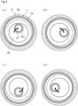
FIG. 4 is a diagram illustrating relative sliding between the sliding surface of the side seal and a sliding surface of a thrust plate in the first embodiment of the present invention. It should be noted thatFIG. 4A illustrates the start position of the relative sliding andFIGS. 4B to 4D illustrate the positional relationships between the relatively sliding surfaces of the side seal and the thrust plate at an eccentric rotary shaft rotation of 90, 180, and 270 degrees, respectively. -
FIG. 5 is a diagram illustrating where the dynamic pressure generated in a dynamic pressure generation groove is generated on the sliding surface of the side seal eccentrically rotating from the state ofFIG. 4A toward the state ofFIG. 4B . -
FIG. 6 is a diagram illustrating a sliding surface of a side seal as a sliding component according to a second embodiment of the present invention. -
FIG. 7 is a diagram illustrating a sliding surface of a side seal as a sliding component according to a third embodiment of the present invention. - Modes for implementing the sliding component according to the present invention will be described below based on embodiments.
- The sliding component according to a first embodiment of the present invention will be described with reference to
FIGS. 1 to 5 . It should be noted that in the drawings, the groove formed in the sliding surface of the sliding component or the like is dotted for convenience of description. - The sliding component according to the first embodiment of the present invention is applied to a rotating machine including an eccentric mechanism such as a scroll compressor C that suctions, compresses, and discharges a refrigerant as a fluid used in the air conditioning system of an automobile or the like. It should be noted that the refrigerant in the present embodiment is a gas mixed with a mist-like lubricating oil.
- First, the scroll compressor C will be described. As illustrated in
FIG. 1 , the scroll compressor C mainly includes ahousing 1, arotary shaft 2, aninner casing 3, ascroll compression mechanism 4, aside seal 7 as a sliding component, athrust plate 8, and a drive motor M. - The
housing 1 includes acylindrical casing 11 and acover 12 blocking an opening of thecasing 11. The drive motor M blocks the opening in thecasing 11 that is on the side axially opposite to the opening in thecasing 11 that is blocked by thecover 12. - Formed in the
casing 11 are a low-pressure chamber 20, a high-pressure chamber 30, and aback pressure chamber 50. A low-pressure refrigerant is supplied from a refrigerant circuit (not illustrated) to the low-pressure chamber 20 as the external space on the low-pressure side through asuction port 10. A high-pressure refrigerant compressed by thescroll compression mechanism 4 is discharged to the high-pressure chamber 30. A part of the refrigerant compressed by thescroll compression mechanism 4 is supplied, together with lubricating oil, to theback pressure chamber 50 as the external space on the high-pressure side. It should be noted that theback pressure chamber 50 is formed in the cylindricalinner casing 3 accommodated in thecasing 11. - A
discharge communication passage 13 is formed in thecover 12. Thedischarge communication passage 13 allows the refrigerant circuit (not illustrated) and the high-pressure chamber 30 to communicate with each other. In addition, a part of a backpressure communication passage 14 for communication between the high-pressure chamber 30 and theback pressure chamber 50 is formed in thecover 12 by branching off from thedischarge communication passage 13. It should be noted that thedischarge communication passage 13 is provided with anoil separator 6 for lubricating oil separation from a refrigerant. - The
inner casing 3 is fixed with an axial end portion of theinner casing 3 abutting against anend plate 41a of a fixedscroll 41 constituting thescroll compression mechanism 4. In addition, theinner casing 3 has a side wall where asuction communication passage 15 penetrating the wall in the radial direction is formed. In other words, the low-pressure chamber 20 is formed from the outside of theinner casing 3 to the inside of theinner casing 3 via thesuction communication passage 15. The refrigerant supplied to the inside of theinner casing 3 through thesuction communication passage 15 is suctioned into thescroll compression mechanism 4. - The
scroll compression mechanism 4 mainly includes the fixedscroll 41 and amovable scroll 42. The fixedscroll 41 is fixed to thecover 12 in a sealed shape. Themovable scroll 42 is accommodated in theinner casing 3. - The fixed
scroll 41 is made of metal and includes aspiral lap 41b. Thespiral lap 41b projects toward themovable scroll 42 from the surface of the disk-shapedend plate 41a, that is, theend plate 41a. In addition, the fixedscroll 41 has a recessedportion 41c where the inner diameter side of the back surface of theend plate 41a, that is, the end surface of theend plate 41a that abuts against thecover 12 is recessed in the direction opposite to thecover 12. The high-pressure chamber 30 is defined from the recessedportion 41c and thecover 12. - The
movable scroll 42 is made of metal and includes aspiral lap 42b. Thespiral lap 42b projects toward the fixedscroll 41 from the surface of a disk-shapedend plate 42a, that is, theend plate 42a. In addition, aboss 42c protruding from the middle of the back surface of theend plate 42a is formed on themovable scroll 42. Aneccentric portion 2a formed on therotary shaft 2 is fitted into theboss 42c so as to be relatively rotatable. It should be noted that an eccentric mechanism causing therotary shaft 2 to perform eccentric rotation is configured by theeccentric portion 2a of therotary shaft 2 and acounterweight portion 2b protruding in the outer diameter direction from therotary shaft 2 in the present embodiment. - When the
rotary shaft 2 is rotationally driven by the drive motor M, theeccentric portion 2a rotates eccentrically and themovable scroll 42 slides, in a posture-maintained state, relative to the fixedscroll 41 with the eccentric rotation. At this time, themovable scroll 42 rotates eccentrically with respect to the fixedscroll 41 and, with this rotation, the contact positions of thelaps compression chamber 40 formed between thelaps compression chamber 40 from the low-pressure chamber 20 formed on the outer diameter side of thescroll compression mechanism 4 is compressed and, finally, the high-pressure refrigerant is discharged to the high-pressure chamber 30 through adischarge hole 41d provided in the middle of the fixedscroll 41. - Next, the
side seal 7 as a sliding component in the present embodiment will be described. As illustrated inFIGS. 2 and3 , theside seal 7 is made of resin and has a rectangular cross section and an annular shape in an axial view. In addition, theside seal 7 is fixed to the back surface of theend plate 42a of the movable scroll 42 (seeFIG. 1 ). It should be noted that a slidingsurface 7a of theside seal 7 is illustrated inFIG. 2 . - The
side seal 7 has the slidingsurface 7a abutting against a slidingsurface 8a (seeFIG. 1 ) of thethrust plate 8. - As illustrated in
FIG. 2 , the slidingsurface 7a of theside seal 7 includes a dynamicpressure generation groove 70 formed in an endless ring shape along the slidingsurface 7a. - As illustrated in
FIGS. 2 and3 , the dynamicpressure generation groove 70 is partitioned by aninner side wall 70a, anouter side wall 70b, and abottom surface 70c. Theinner side wall 70a is formed as a side wall on the inner diameter side extending in the depth direction orthogonal to aflat surface 72a of aland 72 on the inner diameter side. Theouter side wall 70b is formed as a side wall on the outer diameter side extending in the depth direction orthogonal to aflat surface 73a of aland 73 on the outer diameter side. Thebottom surface 70c extends parallel to thesurfaces inner side wall 70a and theouter side wall 70b. - The
inner side wall 70a and theouter side wall 70b have a waveshape extending in the circumferential direction and having an amplitude in the radial direction when viewed from the axial direction. Theinner side wall 70a and theouter side wall 70b have a waveshape with a constant period and a constant amplitude. - It should be noted that in the present embodiment below, the radial apexes in the amplitude of the
inner side wall 70a are referred to as an inner diameter side apex 74 and an outer diameter side apex 75, and the radial apexes in the amplitude of theouter side wall 70b are referred to as an innerdiameter side apex 76 and an outer diameter side apex 77. - Further, it should be noted that the part extending in an S shape from the inner diameter side apex 74 of the
inner side wall 70a toward the outer diameter side apex 75 adjacent to the outer diameter side in the clockwise direction with respect to the middle of theside seal 7 is referred to as anintersection surface 701. In addition, the part extending in an inverted S shape from the inner diameter side apex 74 toward the outer diameter side apex 75 adjacent to the outer diameter side in the counterclockwise direction with respect to the middle of theside seal 7 is referred to as anintersection surface 702. In addition, the part extending in an S shape from the innerdiameter side apex 76 of theouter side wall 70b toward the outer diameter side apex 77 adjacent to the outer diameter side in the clockwise direction with respect to the middle of theside seal 7 is referred to as anintersection surface 703. In addition, the part extending in an inverted S shape from the innerdiameter side apex 76 toward the outer diameter side apex 77 adjacent to the outer diameter side in the counterclockwise direction with respect to the middle of theside seal 7 is referred to as anintersection surface 704. - Specifically, as illustrated in
FIG. 2 , the inner diameter side apexes 74, the outer diameter side apexes 75, the inner diameter side apexes 76, and the outer diameter side apexes 77 each are equally arranged in the circumferential direction. As for the inner diameter side apex 74 and the outer diameter side apex 75 adjacent to each other on theinner side wall 70a, a maximum amplitude L1a on the inner diameter side and a maximum amplitude L1b on the outer diameter side are equal with respect to a virtual reference line α extending on the circumference, and these maximum amplitudes L1a and L1b are equal over the circumferential direction. - Further, as for the inner
diameter side apex 76 and the outer diameter side apex 77 adjacent to each other on theouter side wall 70b, a maximum amplitude L2a on the inner diameter side and a maximum amplitude L2b on the outer diameter side are equal with respect to a virtual reference line β extending on the circumference, and these maximum amplitudes L2a and L2b are equal over the circumferential direction. It should be noted that the maximum amplitudes L1a and L1b and the maximum amplitudes L2a and L2b have the same length (i.e., L1a, L1b = L2a, L2b). - In addition, a circumferential distance L3 (that is, wavelength) between the inner diameter side apexes 74 adjacent on the
inner side wall 70a is constant over the circumferential direction, and a circumferential distance L4 (that is, wavelength) between the inner diameter side apexes 76 adjacent on theouter side wall 70b is constant over the circumferential direction. - In addition, the distance L3 is substantially equal to the distance L4. Strictly speaking, the distance L4 is slightly longer than the distance L3 in terms of length (L3 = L4). It should be noted that although not illustrated, the circumferential distance between the outer diameter side apexes 75 is the same length as the distance L3 and the circumferential distance between the outer diameter side apexes 77 is the same length as the distance L4.
- In addition, the
inner side wall 70a and theouter side wall 70b have a waveshape having a curved surface shape. Specifically, the part near the inner diameter side apex 74 and the innerdiameter side apex 76 is a curved surface convex to the inner diameter side, and the part near the outer diameter side apex 75 and the outer diameter side apex 77 is a curved surface convex to the outer diameter side. - As illustrated in
FIG. 3 , a radial width dimension L5 of the dynamic pressure generation groove 70 (that is, the separation width between theinner side wall 70a and theouter side wall 70b) is constant over the circumferential direction and formed larger than a depth dimension L6 of the dynamic pressure generation groove 70 (i.e., L5 > L6). The radial width dimension L5 is constant over the entire circumference of the dynamicpressure generation groove 70. It should be noted that the width dimension L5 is preferably 10 times or more the depth dimension L6 although the width dimension and the depth dimension of the dynamicpressure generation groove 70 can be freely changed on condition that the width dimension of the dynamicpressure generation groove 70 is formed larger than the depth dimension of the dynamicpressure generation groove 70. It should be noted that for convenience of description, the depth dimension L6 of the dynamicpressure generation groove 70 illustrated inFIG. 3 is deeper than the actual depth dimension L6. - Referring to
FIG. 1 , thethrust plate 8 is made of metal and has an annular shape. In addition, aseal ring 43 is fixed to thethrust plate 8. Theseal ring 43 abuts against the inside surface of theinner casing 3. As a result, thethrust plate 8 functions as a thrust bearing that receives an axial load of themovable scroll 42 via theside seal 7. - In addition, the
side seal 7 and theseal ring 43 partition the low-pressure chamber 20 formed on the outer diameter side of themovable scroll 42 and theback pressure chamber 50 formed on the back surface side of themovable scroll 42 in theinner casing 3. Theback pressure chamber 50 is a closed space formed between theinner casing 3 and therotary shaft 2. Aseal ring 44 is fixed to the inner periphery of a throughhole 3a provided in the middle of the other end of theinner casing 3 and is in sliding contact in a sealed shape with therotary shaft 2 inserted through the throughhole 3a. In addition, the backpressure communication passage 14 allowing the high-pressure chamber 30 and theback pressure chamber 50 to communicate with each other is formed over thecover 12, the fixedscroll 41, and theinner casing 3. In addition, the backpressure communication passage 14 is provided with an orifice (not illustrated) and, after depressurization adjustment by means of the orifice, the refrigerant in the high-pressure chamber 30 is supplied to theback pressure chamber 50 together with the lubricating oil separated by theoil separator 6. At this time, the pressure in theback pressure chamber 50 is adjusted to be higher than the pressure in the low-pressure chamber 20. It should be noted that apressure release hole 16 is formed in theinner casing 3, penetrates theinner casing 3 in the radial direction, and allows the low-pressure chamber 20 and theback pressure chamber 50 to communicate with each other. In addition, apressure adjustment valve 45 is provided in thepressure release hole 16. Thepressure adjustment valve 45 is opened by the pressure of theback pressure chamber 50 exceeding a set value. - In addition, the
boss 42c of themovable scroll 42 is inserted through a throughhole 8b in the middle of thethrust plate 8. The throughhole 8b is formed to have a diameter size at which it is possible to allow eccentric rotation by theeccentric portion 2a of therotary shaft 2 fitted into theboss 42c. In other words, the slidingsurface 7a of theside seal 7 is capable of sliding relative to the slidingsurface 8a of thethrust plate 8 with eccentric rotation by the eccentric rotation of the rotary shaft 2 (seeFIG. 4 ). - It should be noted that
FIGS. 4A to 4D inFIG. 4 illustrate the rotational trajectory of theboss 42c that is viewed from the fixedscroll 41 side and indicated by the black arrows. Respectively illustrated inFIGS. 4B to 4D are theboss 42c rotated by 90 degrees, 180 degrees, and 270 degrees withFIG. 4A serving as the clockwise reference. In addition, the sliding region between the slidingsurface 7a of theside seal 7 and the slidingsurface 8a of thethrust plate 8 is schematically illustrated by dots. In addition, regarding therotary shaft 2, thecounterweight portion 2b constituting the eccentric mechanism and so on are not illustrated and only theeccentric portion 2a fitted into theboss 42c is illustrated for convenience of description. - As described above, the
side seal 7 is a sliding component having the slidingsurface 7a sliding relative to the slidingsurface 8a of thethrust plate 8 with the eccentric rotation. - Next, dynamic pressure generation during the sliding of the
side seal 7 relative to thethrust plate 8 will be described with reference toFIG. 5 . It should be noted thatFIG. 5 illustrates an aspect when theside seal 7 moves from the state ofFIG. 4D toward the state ofFIG. 4A . In addition, inFIG. 5 , theside seal 7 in a case where the slidingsurface 7a is viewed from the axial direction is illustrated, and the circle marks illustrated in the enlarged portions indicate the points where the pressure increases in the dynamicpressure generation groove 70. In addition, a fluid containing, for example, a refrigerant and lubricating oil is stored in the dynamicpressure generation groove 70 even when the rotation is stopped. - As illustrated in
FIG. 5 , when theside seal 7 is to move in the direction of the white arrow, the fluid in the dynamicpressure generation groove 70 moves in the opposite direction relative to the white arrow. As a result, dynamic pressure is generated on theinner side wall 70a and theouter side wall 70b partitioning the dynamicpressure generation groove 70, the slidingsurfaces - Specifically, when the
thrust plate 8 is regarded as an analog clock, the position directly above the paper surface is set to the 12 o'clock position and, at the 12 o'clock position in the dynamicpressure generation groove 70, dynamic pressure is mainly generated on eachintersection surface 701 on theinner side wall 70a. In addition, at the 3 o'clock position in the dynamicpressure generation groove 70, dynamic pressure is mainly generated on eachintersection surface 704 on theouter side wall 70b. In addition, at the 6 o'clock position in the dynamicpressure generation groove 70, dynamic pressure is mainly generated on eachintersection surface 703 on theouter side wall 70b. In addition, at the 9 o'clock position in the dynamicpressure generation groove 70, dynamic pressure is mainly generated on eachintersection surface 702 on theinner side wall 70a. - As described above, the
inner side wall 70a and theouter side wall 70b of the dynamicpressure generation groove 70 extend in the circumferential direction in a waveshape and have the plurality of intersection surfaces 701 to 704 intersecting with respect to the eccentric rotation of theside seal 7. Accordingly, dynamic pressure can be generated by the intersection surfaces 701 to 704 regardless of the eccentric rotation angle of theside seal 7, the slidingsurfaces surfaces surfaces - In addition, at the 12 o'clock and 6 o'clock positions in the dynamic
pressure generation groove 70, the intersection surfaces 701 and 703 have a concave shape holding the fluid in the dynamicpressure generation groove 70 that moves toward the opposite direction relative to the white arrow. Accordingly, the fluid near the intersection surfaces 701 and 703 is unlikely to be dispersed in the circumferential direction, and dynamic pressure is generated with ease. In other words, a larger dynamic pressure is generated at the 12 o'clock and 6 o'clock positions in the dynamicpressure generation groove 70 than at the 3 o'clock and 9 o'clock positions in the dynamicpressure generation groove 70. - It should be noted that
FIG. 5 illustrates a form when theside seal 7 moves from the state ofFIG. 4D toward the state ofFIG. 4A , dynamic pressure is generated in substantially the same form when theside seal 7 moves from the state ofFIG. 4D toward the state ofFIG. 4A , when theside seal 7 moves from the state ofFIG. 4A toward the state ofFIG. 4B , when theside seal 7 moves from the state ofFIG. 4B toward the state ofFIG. 4C , and when theside seal 7 moves from the state ofFIG. 4C toward the state ofFIG. 4D , and thus description is omitted as to the forms when theside seal 7 moves from the state ofFIG. 4A toward the state ofFIG. 4B , from the state ofFIG. 4B toward the state ofFIG. 4C , and from the state ofFIG. 4C toward the state ofFIG. 4D . - In addition, in the sliding of the
side seal 7 relative to thethrust plate 8 and entailing eccentric rotation, the position where a large dynamic pressure is generated in the dynamicpressure generation groove 70 continuously moves along the circumferential direction of the dynamicpressure generation groove 70 in accordance with the movement direction of the slidingsurface 7a of theside seal 7. Accordingly, a state where the relative inclination between the slidingsurfaces - In addition, the dynamic
pressure generation groove 70 is formed in an annular shape, and thus dynamic pressure can be generated over the entire circumference of the slidingsurface 7a and the inclination of the slidingsurfaces side seal 7. - In addition, the
inner side wall 70a and theouter side wall 70b have a waveshape with a constant period, and thus dynamic pressure can be equally generated over the circumferential direction of the slidingsurface 7a. - In addition, the
inner side wall 70a and theouter side wall 70b have a waveshape having a curved surface shape, and thus the movement of the fluid in the dynamicpressure generation groove 70 becomes smooth and dynamic pressure can be stably generated. - In addition, the
back pressure chamber 50 extends to the inner diameter side of the slidingsurfaces surfaces back pressure chamber 50 is introduced from the inner diameter side of the slidingsurfaces scroll compression mechanism 4 is driven, the pressure of theback pressure chamber 50 increases, a high-pressure fluid is introduced between the slidingsurfaces back pressure chamber 50, and thus the slidingsurfaces - In addition, although the present embodiment exemplifies a form in which the radial width dimension L5 (that is, the separation width between the
inner side wall 70a and theouter side wall 70b) of the dynamicpressure generation groove 70 is constant over the entire circumference, the present invention is not limited thereto. In an alternative disposition, the radial width dimension of the dynamic pressure generation groove may be different at different positions in the circumferential direction of the dynamic pressure generation groove. For example, the inner side wall and the outer side wall may be formed in waveshapes with different amplitudes. - Next, a dynamic
pressure generation groove 170 of aside seal 107 as a sliding component according to a second embodiment of the present invention will be described with reference toFIG. 6 . It should be noted that the description of configurations identical to those of the first embodiment will be omitted for redundancy avoidance. - As for the
side seal 107 in the second embodiment illustrated inFIG. 6 , a plurality of the dynamicpressure generation grooves 170 extending in an arc shape in the circumferential direction are disposed apart from each other in the circumferential direction of a slidingsurface 107a. - According to this, dynamic pressure can be generated in both
circumferential end portions pressure generation groove 170 in addition to aninner side wall 170a and anouter side wall 170b of each dynamicpressure generation groove 170. It should be noted that in this case, it is preferable that the dynamicpressure generation grooves 170 are equally arranged in the circumferential direction. - Next, a dynamic
pressure generation groove 270 of aside seal 207 as a sliding component according to a third embodiment of the present invention will be described with reference toFIG. 7 . It should be noted that the description of configurations identical to those of the first embodiment will be omitted for redundancy avoidance. - As for the dynamic
pressure generation groove 270 of theside seal 207 in the third embodiment illustrated inFIG. 7 , an inner side wall 270a is wavy when viewed from the axial direction. In addition, an outer side wall 270b is circular when viewed from the axial direction. In this manner, the dynamic pressure generation groove may be wavy on at least one of the inner and outer side walls. - In addition, the inner side wall 270a has an outer
diameter side apex 275 that tapers with an acute angle. In addition, the inner side wall 270a has a waveshape. According to this, the circumferential width of the outerdiameter side apex 275 can be reduced, and thus it is possible to ensure alarge intersection surface 271 that has a circular arc shape, is convex to the inner diameter side, and is formed between the outer diameter side apexes 275 adjacent to each other. - Although embodiments of the present invention have been described above with reference to the drawings, the specific configurations are not limited to the embodiments and any changes or additions within the scope of the present invention are included in the present invention.
- For example, although a form in which the inner and outer side walls have a waveshape having a curved surface shape has been exemplified in the first to third embodiments, the present invention is not limited thereto and the waveshape may be, for example, rectangular or triangular when viewed from the axial direction.
- In addition, although an aspect in which the
side seal 7 as a sliding component is applied to the scroll compressor C used in the air conditioning system of an automobile or the like has been described in the first to third embodiments, the present invention is not limited thereto and theside seal 7 as a sliding component may be applied to, for example, a scroll expansion compressor provided integrally with an expander and a compressor insofar as it is a rotating machine including an eccentric mechanism. - In addition, each of the fluids in the spaces inside and outside the sliding surface of the sliding component may be any of a gas, a liquid, and a gas-liquid mixture.
- In addition, insofar as the sliding component of the present invention has a sliding surface that relatively slides with eccentric rotation, the sliding component of the present invention may be used in an environment in which the pressure inside the sliding surface and the pressure outside the sliding surface are equal to each other without being limited to an environment in which there is a pressure difference between the inside and outside of the sliding surface. In addition, the sliding component of the present invention does not have to function as a seal and may be one capable of stably reducing the frictional resistance of a sliding surface.
- In addition, although the side seal having the relatively sliding surface is made of resin and the thrust plate is made of metal in the first to third embodiments, the material of the sliding component may be freely selected in accordance with the environment of use and so on.
- In addition, although an aspect in which a dynamic pressure generation groove is formed in the sliding surface of the side seal has been described in the first to third embodiments, the present invention is not limited thereto. A dynamic pressure generation groove may be formed in the sliding region of the sliding surface of the thrust plate (see
FIG. 4 ), which is a sliding component having a sliding surface relatively sliding with eccentric rotation. In addition, dynamic pressure generation grooves may be formed in both the sliding surface of the side seal and the sliding surface of the thrust plate. - In addition, although a configuration in which the sliding surface of the side seal and the sliding surface of the thrust plate as a sliding component slide relative to each other with eccentric rotation has been described in the first to third embodiments, the present invention is not limited thereto. A dynamic pressure generation groove may be formed in the sliding surface relatively sliding with eccentric rotation with only one of the side seal and the thrust plate provided. For example, in a case where only the thrust plate is provided, dynamic pressure generation grooves may be formed in one or both of the sliding surface of the thrust plate as a sliding component and the back surface of the end plate of the movable scroll. In addition, in a case where only the side seal is provided, a dynamic pressure generation groove may be formed in the sliding surface of the side seal as a sliding component. In this case, the side seal also functions as a thrust bearing that abuts against the inner peripheral surface of the inner casing and receives the axial load of the movable scroll.
- In addition, in a case where the side seal and the thrust plate are not provided and the back surface of the end plate of the movable scroll functions as a thrust bearing that abuts against the inner peripheral surface of the inner casing and receives the axial load of the movable scroll, a dynamic pressure generation groove may be formed in the sliding surface formed on the back surface of the end plate of the movable scroll.
- In addition, the sliding surface may be provided with a conduction groove for conduction between the external space on the inner diameter side or the outer diameter side of the sliding surface and the dynamic pressure generation groove.
- In addition, although a form in which the external space on the low-pressure side is on the outer diameter side of the side seal and the high-pressure external space is on the inner diameter side of the side seal has been exemplified, the external space on the low-pressure side may be on the inner diameter side of the side seal with the high-pressure external space on the outer diameter side of the side seal.
-
- 4
- Scroll compression mechanism
- 7
- Side seal (sliding component)
- 7a
- Sliding surface
- 8
- Thrust plate
- 8a
- Sliding surface
- 20
- Low-pressure chamber (external space on outer diameter side)
- 30
- High-pressure chamber
- 40
- Compression chamber
- 41
- Fixed scroll
- 42
- Movable scroll
- 50
- Back pressure chamber (external space on inner diameter side, external space on high-pressure side)
- 70
- Dynamic pressure generation groove
- 70a
- Inner side wall (side wall on inner diameter side)
- 70b
- Outer side wall (side wall on outer diameter side)
- 107
- Side seal (sliding component)
- 107a
- Sliding surface
- 170
- Dynamic pressure generation groove
- 170a
- Inner side wall (side wall on inner diameter side)
- 170b
- Outer side wall (side wall on outer diameter side)
- 207
- Side seal (sliding component)
- 270a
- Inner side wall (side wall on inner diameter side)
- 270b
- Outer side wall (side wall on outer diameter side)
- 271
- Intersection surface
- 701 to 704
- Intersection surface
- C
- Scroll compressor
- M
- Drive motor
Claims (5)
- A sliding component having a sliding surface relatively sliding with eccentric rotation,
wherein the sliding surface is provided with a dynamic pressure generation groove defined by side walls extending in a circumferential direction, at least one of the side walls being formed in a waveshape with amplitude in a radial direction. - The sliding component according to claim 1, wherein both the side walls of the dynamic pressure generation groove are formed in the waveshape with the amplitude in the radial direction.
- The sliding component according to claim 1 or 2, wherein the dynamic pressure generation groove is formed in an annular shape.
- The sliding component according to any one of claims 1 to 3, wherein the waveshape of the side wall is periodically formed with a constant pitch.
- The sliding component according to any one of claims 1 to 4, wherein the waveshape of the side wall is formed by curved surfaces.
Applications Claiming Priority (2)
| Application Number | Priority Date | Filing Date | Title |
|---|---|---|---|
| JP2020116359 | 2020-07-06 | ||
| PCT/JP2021/024944 WO2022009770A1 (en) | 2020-07-06 | 2021-07-01 | Sliding component |
Publications (2)
| Publication Number | Publication Date |
|---|---|
| EP4177487A1 true EP4177487A1 (en) | 2023-05-10 |
| EP4177487A4 EP4177487A4 (en) | 2024-07-24 |
Family
ID=79552531
Family Applications (1)
| Application Number | Title | Priority Date | Filing Date |
|---|---|---|---|
| EP21837223.3A Withdrawn EP4177487A4 (en) | 2020-07-06 | 2021-07-01 | SLIDING COMPONENT |
Country Status (6)
| Country | Link |
|---|---|
| US (1) | US12404935B2 (en) |
| EP (1) | EP4177487A4 (en) |
| JP (1) | JP7497132B2 (en) |
| KR (1) | KR20230027188A (en) |
| CN (1) | CN115735073A (en) |
| WO (1) | WO2022009770A1 (en) |
Families Citing this family (2)
| Publication number | Priority date | Publication date | Assignee | Title |
|---|---|---|---|---|
| JP7523370B2 (en) * | 2021-01-22 | 2024-07-26 | サンデン株式会社 | Scroll Compressor |
| KR20250041053A (en) * | 2022-11-17 | 2025-03-25 | 이구루코교 가부시기가이샤 | Thrust receiving mechanism |
Family Cites Families (219)
| Publication number | Priority date | Publication date | Assignee | Title |
|---|---|---|---|---|
| US1876515A (en) * | 1932-09-06 | Shaft packing | ||
| US2244450A (en) * | 1938-04-28 | 1941-06-03 | Bbc Brown Boveri & Cie | Packing gland |
| US3380040A (en) | 1964-04-01 | 1968-04-23 | Hughes Aircraft Co | Hydrodynamic bearing support for a magnetic drum |
| US3383116A (en) | 1964-09-30 | 1968-05-14 | J C Carter Company | Face seal |
| GB1097660A (en) * | 1965-07-22 | 1968-01-03 | Stenberg Flygt Ab | A cooling device for sealing rings |
| FR1505487A (en) | 1966-10-28 | 1967-12-15 | Guinard Pompes | Improvement in leak-controlled rotary joints |
| US3695789A (en) | 1970-04-13 | 1972-10-03 | Case Co J I | Balancing mechanism for fluid translating device |
| US3704019A (en) | 1970-06-19 | 1972-11-28 | Gen Electric | Spiral groove face seals |
| US3675935A (en) | 1970-07-13 | 1972-07-11 | Nasa | Spiral groove seal |
| US3782737A (en) | 1970-07-13 | 1974-01-01 | Nasa | Spiral groove seal |
| US4056478A (en) | 1973-10-04 | 1977-11-01 | Sargent Industries, Inc. | Bearing material employing frangible microcapsules containing lubricant |
| JPS5134974A (en) | 1974-09-19 | 1976-03-25 | Kinugawa Rubber Ind | Dainamitsukushiiru no seiho |
| DE2504204C3 (en) | 1975-02-01 | 1981-11-12 | Skf Kugellagerfabriken Gmbh, 8720 Schweinfurt | Self-pressure generating axial slide bearing |
| FR2342440A1 (en) | 1976-02-27 | 1977-09-23 | Ca Atomic Energy Ltd | Face seal for rotating shaft - has collar with chain of blind holes connected by grooves to increase resistance to flow |
| DE2610045C2 (en) | 1976-03-11 | 1982-06-16 | M.A.N. Maschinenfabrik Augsburg-Nürnberg AG, 4200 Oberhausen | Gas-locked shaft seal |
| DE2622772C3 (en) | 1976-05-21 | 1980-05-08 | Hoesch Werke Ag, 4600 Dortmund | Device for transporting and changing rolls on roll processing machines |
| JPS57163770A (en) | 1981-04-01 | 1982-10-08 | Eagle Ind Co Ltd | Mechanical seal |
| DE3223703C2 (en) | 1982-06-25 | 1984-05-30 | M.A.N. Maschinenfabrik Augsburg-Nürnberg AG, 4200 Oberhausen | Gas-locked shaft seal with radial sealing gap |
| JPS59195254A (en) | 1983-04-20 | 1984-11-06 | Fujitsu Ltd | Printing device |
| JPS59195253A (en) | 1983-04-20 | 1984-11-06 | Canon Inc | Electrophotographic apparatus |
| SU1162279A1 (en) * | 1984-06-07 | 1993-06-15 | V S Chekhovich | Face seal for main circulating pump of nuclear power plants |
| JPS618402A (en) | 1984-06-20 | 1986-01-16 | Daikin Ind Ltd | Scroll type hydraulic machine |
| JPH0647991B2 (en) | 1986-05-15 | 1994-06-22 | 三菱電機株式会社 | Scroll compressor |
| CH677266A5 (en) | 1986-10-28 | 1991-04-30 | Pacific Wietz Gmbh & Co Kg | |
| JPS63134883A (en) | 1986-11-27 | 1988-06-07 | Mitsubishi Electric Corp | Scroll compressor |
| US4836561A (en) * | 1987-02-17 | 1989-06-06 | University Of New Mexico | Wavy-tilt-dam seal ring |
| US4889348A (en) | 1987-06-10 | 1989-12-26 | John Crane-Houdaille, Inc. | Spiral groove seal system for high vapor-pressure liquids |
| JP2541227B2 (en) | 1987-07-08 | 1996-10-09 | 三菱電機株式会社 | Scroll compressor |
| JPH0216381A (en) | 1988-07-01 | 1990-01-19 | Daikin Ind Ltd | Scroll type fluid device |
| JPH02136863A (en) | 1988-11-18 | 1990-05-25 | Toshiba Corp | Developer for image forming device |
| DE3839106A1 (en) | 1988-11-18 | 1990-05-23 | Burgmann Dichtungswerk Feodor | MECHANICAL SEAL |
| JPH06105105B2 (en) | 1989-03-03 | 1994-12-21 | 日本ピラー工業株式会社 | Non-contact end face mechanical seal |
| US5316455A (en) | 1989-10-25 | 1994-05-31 | Matsushita Refrigeration Company | Rotary compressor with stabilized rotor |
| JPH0660690B2 (en) | 1990-06-18 | 1994-08-10 | 日本ピラー工業株式会社 | Dynamic pressure non-contact mechanical seal |
| JPH0756345B2 (en) | 1990-07-09 | 1995-06-14 | 株式会社荏原製作所 | Non-contact end face seal |
| US5071141A (en) | 1990-07-17 | 1991-12-10 | John Crane Inc. | Spiral groove seal arrangement for high vapor-pressure liquids |
| US5224714A (en) | 1990-07-18 | 1993-07-06 | Ebara Corporation | Noncontacting face seal |
| JPH07117167B2 (en) | 1991-05-09 | 1995-12-18 | 日本ピラー工業株式会社 | Non-contact mechanical seal device |
| JP3024267B2 (en) | 1991-06-11 | 2000-03-21 | 松下電器産業株式会社 | Scroll compressor |
| JP2516301B2 (en) | 1991-06-13 | 1996-07-24 | インターナショナル・ビジネス・マシーンズ・コーポレイション | Tape drive |
| US5174584A (en) | 1991-07-15 | 1992-12-29 | General Electric Company | Fluid bearing face seal for gas turbine engines |
| JPH0560247A (en) | 1991-08-26 | 1993-03-09 | Nippon Pillar Packing Co Ltd | Noncontact type mechanical seal |
| JPH0680623B2 (en) | 1991-09-25 | 1994-10-12 | 北海道電力株式会社 | Power transformers for power supply and demand |
| US5447316A (en) | 1992-02-06 | 1995-09-05 | Eagle Industry Co., Ltd. | Gas seal |
| JPH05296248A (en) | 1992-04-21 | 1993-11-09 | Sumitomo Electric Ind Ltd | Sliding member |
| JP3517888B2 (en) | 1992-09-18 | 2004-04-12 | ブラザー工業株式会社 | Color electrophotographic image forming apparatus |
| MY108842A (en) | 1992-09-21 | 1996-11-30 | Koninklijke Philips Electronics Nv | Method of manufacturing a dynamic groove bearing, die suitable for use in such a method, and housing and bearing part manufactured by such a method; data storage unit provided with such a groove bearing, method of manufacturing a rotable scanning unit, and magnetic tape device provided with such a scanning unit |
| JPH0769020B2 (en) | 1992-10-07 | 1995-07-26 | 日本ピラー工業株式会社 | mechanical seal |
| JPH0769021B2 (en) | 1992-12-11 | 1995-07-26 | 日本ピラー工業株式会社 | Non-contact type shaft seal device |
| JPH0743038A (en) | 1993-07-30 | 1995-02-10 | Mitsubishi Heavy Ind Ltd | Absorption refrigerator |
| US5441283A (en) | 1993-08-03 | 1995-08-15 | John Crane Inc. | Non-contacting mechanical face seal |
| AU685502B2 (en) * | 1993-09-01 | 1998-01-22 | Durametallic Corporation | Face seal with angled and annular grooves |
| US5558341A (en) | 1995-01-11 | 1996-09-24 | Stein Seal Company | Seal for sealing an incompressible fluid between a relatively stationary seal and a movable member |
| US5769604A (en) | 1995-05-04 | 1998-06-23 | Eg&G Sealol, Inc. | Face seal device having high angular compliance |
| JP2903458B2 (en) | 1995-09-29 | 1999-06-07 | 日本ピラー工業株式会社 | Hot water shaft sealing device for large water circulation pump |
| JP3696683B2 (en) | 1996-02-21 | 2005-09-21 | 株式会社日立製作所 | Scroll compressor |
| JPH09292034A (en) | 1996-04-25 | 1997-11-11 | Mitsubishi Heavy Ind Ltd | Mechanical seal |
| US5833518A (en) | 1996-08-02 | 1998-11-10 | Flowserve Management Company | Method for forming a wavy face ring |
| US5834094A (en) | 1996-09-30 | 1998-11-10 | Surface Technologies Ltd. | Bearing having micropores and design method thereof |
| JPH10281299A (en) | 1997-04-11 | 1998-10-23 | Mitsubishi Heavy Ind Ltd | Mechanical seal device |
| JPH10292867A (en) | 1997-04-16 | 1998-11-04 | Mitsubishi Heavy Ind Ltd | Gas seal device |
| JP3041592B2 (en) | 1997-06-05 | 2000-05-15 | 株式会社ゼクセル | Horizontal scroll compressor |
| US6152452A (en) | 1997-10-17 | 2000-11-28 | Wang; Yuming | Face seal with spiral grooves |
| JPH11132163A (en) | 1997-10-23 | 1999-05-18 | Zexel:Kk | Transverse installation type scroll compressor |
| BR9714210A (en) | 1997-11-21 | 2000-03-28 | Nippon Pillar Packing | Static pressure non-contact gas sealing |
| CN1133834C (en) | 1997-11-21 | 2004-01-07 | 日本皮拉工业株式会社 | Static pressure non-contact air seal |
| JPH11287329A (en) | 1998-04-03 | 1999-10-19 | Eagle Ind Co Ltd | Sliding material |
| JPH11303858A (en) | 1998-04-17 | 1999-11-02 | Matsushita Electric Ind Co Ltd | Dynamic pressure porous bearing |
| JP3066367B1 (en) | 1999-03-04 | 2000-07-17 | 日本ピラー工業株式会社 | Shaft sealing device |
| US6213473B1 (en) | 1999-03-06 | 2001-04-10 | Utex Industries, Inc. | Double gas seal with coplanar pad faces |
| JP4232278B2 (en) | 1999-06-25 | 2009-03-04 | パナソニック株式会社 | Hydrodynamic bearing and spindle motor equipped with the same |
| US7044470B2 (en) | 2000-07-12 | 2006-05-16 | Perkinelmer, Inc. | Rotary face seal assembly |
| US6446976B1 (en) | 2000-09-06 | 2002-09-10 | Flowserve Management Company | Hydrodynamic face seal with grooved sealing dam for zero-leakage |
| DE10048256A1 (en) | 2000-09-29 | 2002-04-25 | Federal Mogul Wiesbaden Gmbh | Welding process to make camshaft bearing uses angled presentation to compensate for subsequent cooling |
| CN2460801Y (en) | 2001-01-18 | 2001-11-21 | 王玉明 | Sealing device for spiral flute end capable of bidirectional rotation |
| US6655693B2 (en) | 2001-04-26 | 2003-12-02 | John Crane Inc. | Non-contacting gas compressor seal |
| JP2003074449A (en) | 2001-09-05 | 2003-03-12 | Denso Corp | Starter |
| US6692006B2 (en) | 2001-10-15 | 2004-02-17 | Stein Seal Company | High-pressure film-riding seals for rotating shafts |
| JP4054608B2 (en) | 2002-05-23 | 2008-02-27 | イーグル工業株式会社 | Plate brush seal |
| CN100427816C (en) | 2002-09-20 | 2008-10-22 | 徐万福 | Helical flute and face mechanial seal composed of angular microflute group |
| JP4316956B2 (en) | 2002-10-23 | 2009-08-19 | イーグル工業株式会社 | Sliding parts |
| DE10324849B4 (en) | 2003-06-02 | 2005-12-22 | Minebea Co., Ltd. | Electric motor with a shaft seal for sealing a motor shaft of the electric motor |
| JP2005124255A (en) | 2003-10-14 | 2005-05-12 | Asmo Co Ltd | Motor rotating shaft, motor rotating shaft thrust bearing structure, motor with reduction gear, and method of manufacturing motor rotating shaft |
| CN1261698C (en) | 2003-10-15 | 2006-06-28 | 哈尔滨工业大学 | Dynamic pressure ball bearing with inclined air collection groove |
| JP4296292B2 (en) | 2003-10-31 | 2009-07-15 | 株式会社豊田中央研究所 | Fluid bearing |
| KR100548489B1 (en) | 2003-12-20 | 2006-02-02 | 엘지전자 주식회사 | Oil supply structure of scroll compressor |
| JP4719414B2 (en) | 2003-12-22 | 2011-07-06 | イーグル工業株式会社 | Sliding parts |
| JP4119398B2 (en) | 2004-04-30 | 2008-07-16 | 日本ピラー工業株式会社 | Non-contact mechanical seal |
| GB2413603A (en) | 2004-04-30 | 2005-11-02 | Corac Group Plc | A dry gas seal assembly |
| US7377518B2 (en) | 2004-05-28 | 2008-05-27 | John Crane Inc. | Mechanical seal ring assembly with hydrodynamic pumping mechanism |
| JP2006009614A (en) | 2004-06-23 | 2006-01-12 | Matsushita Electric Ind Co Ltd | Scroll compressor |
| JP4262656B2 (en) | 2004-09-10 | 2009-05-13 | 日本ピラー工業株式会社 | Non-contact type sealing device |
| JP2006090524A (en) | 2004-09-27 | 2006-04-06 | Nissei Co Ltd | Dynamic pressure fluid bearing |
| JP4820471B2 (en) | 2004-11-09 | 2011-11-24 | イーグル工業株式会社 | Mechanical seal device |
| JP2006183702A (en) | 2004-12-27 | 2006-07-13 | Hitachi Industrial Equipment Systems Co Ltd | Thrust bearing |
| JP4511412B2 (en) | 2005-05-11 | 2010-07-28 | 株式会社デンソー | Scroll compressor |
| JP2007162045A (en) | 2005-12-12 | 2007-06-28 | Japan Science & Technology Agency | Sliding material and manufacturing method thereof |
| US20070228664A1 (en) | 2006-03-31 | 2007-10-04 | Krishnamurthy Anand | Mechanical seals and methods of making |
| US7793940B2 (en) | 2006-05-16 | 2010-09-14 | Skf Usa Inc. | Mechanical end face seal with ultrahard face material |
| EP2047149B1 (en) | 2006-05-26 | 2015-08-12 | Sulzer Metco (US) Inc. | Mechanical seals and method of manufacture |
| US20080284105A1 (en) | 2006-06-21 | 2008-11-20 | Thurai Manik Vasagar | Low and reverse pressure application hydrodynamic pressurizing seals |
| WO2008013147A1 (en) | 2006-07-25 | 2008-01-31 | Eagle Industry Co., Ltd. | Mechanical seal device |
| US7878777B2 (en) | 2006-08-25 | 2011-02-01 | Denso Corporation | Scroll compressor having grooved thrust bearing |
| JP4772623B2 (en) | 2006-08-25 | 2011-09-14 | 株式会社デンソー | Scroll compressor |
| JP4709713B2 (en) * | 2006-08-25 | 2011-06-22 | 株式会社デンソー | Scroll compressor |
| JP4906438B2 (en) | 2006-08-25 | 2012-03-28 | 株式会社デンソー | Scroll compressor |
| US8162322B2 (en) | 2006-10-25 | 2012-04-24 | Rexnord Industries, Llc | Hydrodynamic seal with circumferentially varying lift force |
| EP2213915B1 (en) | 2007-11-20 | 2018-05-23 | Eagle Industry Co., Ltd. | Mechanical seal and tandem seal |
| US20090326087A1 (en) | 2008-06-27 | 2009-12-31 | Xerox Corporation | Method for treating microcapsules for use in imaging member |
| DE102008038396A1 (en) | 2008-08-19 | 2010-02-25 | Surcoatec International Ag | Sliding ring for a mechanical seal |
| JP5271679B2 (en) | 2008-12-02 | 2013-08-21 | 三菱重工業株式会社 | Scroll compressor |
| US8100405B2 (en) | 2009-01-06 | 2012-01-24 | General Electric Company | System and method for providing compliant rotating seals |
| JP5757087B2 (en) | 2009-02-10 | 2015-07-29 | Nok株式会社 | Sliding member and manufacturing method thereof |
| EP2375112B1 (en) | 2009-05-25 | 2018-07-18 | Eagle Industry Co., Ltd. | Sealing device |
| CN101793324B (en) | 2009-08-06 | 2011-12-28 | 浙江工业大学 | Hydrodynamic mechanical seal structure for three-dimensional fish scale-like texture bottom surface type groove |
| CN201496542U (en) | 2009-08-06 | 2010-06-02 | 浙江工业大学 | Three-dimensional fish scale-constructed underside-type trough fluid dynamic-pressure type liquid mechanical sealing structure |
| CN101644333B (en) | 2009-08-20 | 2011-08-31 | 浙江工业大学 | Gas end surface sealing structure with three-dimensional feather-like textured bottom shaped grooves |
| US7931277B2 (en) | 2009-08-27 | 2011-04-26 | Stein Seal Company | Hydrodynamic circumferential seal system for large translations |
| JP2011074931A (en) | 2009-09-29 | 2011-04-14 | Ihi Corp | Sealing device for combustible gas compressor |
| CN102483162A (en) | 2010-02-26 | 2012-05-30 | Nok株式会社 | sealing ring |
| JP5518527B2 (en) | 2010-03-04 | 2014-06-11 | イーグル工業株式会社 | Sliding parts |
| EP2549155B1 (en) | 2010-03-15 | 2016-08-10 | Eagle Industry Co., Ltd. | Sliding member |
| JP5122607B2 (en) | 2010-06-17 | 2013-01-16 | キヤノンマシナリー株式会社 | Flat sliding mechanism |
| DE202010011173U1 (en) | 2010-08-09 | 2011-12-22 | Eagleburgmann Germany Gmbh & Co. Kg | Sliding ring with improved inlet properties |
| JP2012062534A (en) | 2010-09-16 | 2012-03-29 | Jtekt Corp | Sliding member |
| CN103097782B (en) | 2010-10-06 | 2016-01-20 | 伊格尔工业股份有限公司 | Slide member |
| JP2012082794A (en) | 2010-10-14 | 2012-04-26 | Sanden Corp | Scroll fluid machine |
| JP2012122135A (en) | 2010-11-18 | 2012-06-28 | Furukawa Electric Co Ltd:The | Plating assistant, plating liquid, and plating material |
| CN201972927U (en) | 2010-12-22 | 2011-09-14 | 艾默生环境优化技术有限公司 | Thrust plate for horizontal vortex compressor and horizontal vortex compressor |
| CN102777606A (en) * | 2011-05-09 | 2012-11-14 | 刘讯岐 | Wavy-groove sealing ring structure |
| JP5871289B2 (en) | 2011-09-03 | 2016-03-01 | イーグル工業株式会社 | Sliding parts |
| US9447884B2 (en) * | 2011-09-03 | 2016-09-20 | Eagle Industry Co., Ltd. | Sliding parts |
| CN103732958B (en) | 2011-09-10 | 2016-09-21 | 伊格尔工业股份有限公司 | Slide unit |
| WO2013035502A1 (en) | 2011-09-10 | 2013-03-14 | イーグル工業株式会社 | Sliding component |
| DE102011116162A1 (en) | 2011-10-14 | 2013-04-18 | Eagleburgmann Germany Gmbh & Co. Kg | Sliding ring of a mechanical seal assembly with run-time-prolonging properties and process for its preparation |
| JP5767959B2 (en) | 2011-12-22 | 2015-08-26 | 大豊工業株式会社 | Sliding member |
| JP6037622B2 (en) | 2012-02-16 | 2016-12-07 | 三菱重工業株式会社 | Scroll compressor |
| JP5928106B2 (en) | 2012-04-02 | 2016-06-01 | オイレス工業株式会社 | Static pressure gas bearing and linear motion guide device using the static pressure gas bearing |
| CN104169622B (en) | 2012-05-21 | 2016-04-27 | 伊格尔工业股份有限公司 | Slide member |
| EP2881632B1 (en) | 2012-08-04 | 2018-04-04 | Eagle Industry Co., Ltd. | Sliding component |
| US9958010B2 (en) | 2012-08-04 | 2018-05-01 | Eagle Industry Co., Ltd. | Sliding component |
| WO2014042045A1 (en) | 2012-09-11 | 2014-03-20 | イーグル工業株式会社 | Slide part |
| US9347566B2 (en) | 2012-10-18 | 2016-05-24 | Eagle Industry Co., Ltd. | Sliding component |
| US9964215B2 (en) | 2012-12-25 | 2018-05-08 | Eagle Industry Co., Ltd. | Sliding component |
| WO2014116800A1 (en) | 2013-01-23 | 2014-07-31 | Flowserve Management Company | Mechanical face seal with a reverse trapezoidal face pattern |
| CN203098871U (en) | 2013-01-30 | 2013-07-31 | 浙江工业大学 | Mushroom-like groove bidirectional rotating fluid moving compression mechanical sealing structure |
| JP6219367B2 (en) | 2013-03-14 | 2017-10-25 | イーグルブルグマンジャパン株式会社 | Mechanical seal device |
| AU2014239820B2 (en) | 2013-03-17 | 2016-07-21 | Eagle Industry Co., Ltd. | Sliding component |
| EP2977655B1 (en) | 2013-03-17 | 2018-07-18 | Eagle Industry Co., Ltd. | Sliding part |
| CN104919229B (en) | 2013-04-24 | 2017-05-31 | 伊格尔工业股份有限公司 | sliding parts |
| GB2513867A (en) | 2013-05-07 | 2014-11-12 | Mahle Int Gmbh | Sliding engine component |
| CN103267132B (en) | 2013-05-28 | 2015-08-05 | 南京林业大学 | From the mechanical seal of pumping Hydrodynamic pressure type |
| CN203641506U (en) | 2013-08-20 | 2014-06-11 | 浙江工业大学 | Tilted gradually-changed porous end surface non-contact mechanical seal structure |
| JP6210814B2 (en) | 2013-09-26 | 2017-10-11 | ポリプラスチックス株式会社 | Sliding member |
| JP2015068330A (en) | 2013-10-01 | 2015-04-13 | 三菱重工業株式会社 | Sliding member |
| CN103557229A (en) | 2013-10-22 | 2014-02-05 | 申科滑动轴承股份有限公司 | Design method of water lubrication step tile dynamic pressure thrust bearing |
| CN103557334A (en) | 2013-11-14 | 2014-02-05 | 江苏大学 | Multiple-end face combined type mechanical seal for realizing zero leakage and non-contact |
| US10865883B2 (en) | 2014-01-24 | 2020-12-15 | Nok Corporation | Sealing ring |
| EP3112078B1 (en) | 2014-02-24 | 2020-04-15 | Eagle Industry Co., Ltd. | Sliding member and sliding member processing method |
| JP6329411B2 (en) | 2014-03-25 | 2018-05-23 | Ntn株式会社 | Internal gear pump |
| US20150345642A1 (en) | 2014-05-29 | 2015-12-03 | Caterpillar Inc. | Thin film coating on mechanical face seals |
| EP3190317B1 (en) | 2014-09-04 | 2022-02-09 | Eagle Industry Co., Ltd. | Mechanical seal |
| JP6548880B2 (en) | 2014-09-17 | 2019-07-24 | 三菱重工サーマルシステムズ株式会社 | Scroll compressor |
| EP3196516B1 (en) | 2014-09-20 | 2019-08-21 | Eagle Industry Co., Ltd. | Sliding component |
| JP6224568B2 (en) | 2014-10-17 | 2017-11-01 | イーグル工業株式会社 | mechanical seal |
| US10443737B2 (en) * | 2014-11-08 | 2019-10-15 | Eagle Industry Co., Ltd. | Slide component |
| EP3929455B1 (en) | 2014-12-22 | 2026-01-28 | Eagle Industry Co., Ltd. | Plain bearing and pump |
| KR101970231B1 (en) | 2015-02-14 | 2019-04-18 | 이구루코교 가부시기가이샤 | Sliding parts |
| EP3284981B1 (en) | 2015-04-15 | 2020-11-04 | Eagle Industry Co., Ltd. | Sliding parts |
| WO2016167170A1 (en) | 2015-04-16 | 2016-10-20 | イーグル工業株式会社 | Sliding part |
| WO2016186019A1 (en) | 2015-05-19 | 2016-11-24 | イーグル工業株式会社 | Sliding component |
| JP6595589B2 (en) | 2015-05-20 | 2019-10-23 | イーグル工業株式会社 | Sliding parts |
| JP6678170B2 (en) | 2015-05-21 | 2020-04-08 | イーグル工業株式会社 | Sliding parts |
| JP6776232B2 (en) | 2015-06-15 | 2020-10-28 | イーグル工業株式会社 | Sliding parts |
| WO2017002774A1 (en) | 2015-06-30 | 2017-01-05 | イーグル工業株式会社 | Seal device |
| US10274087B2 (en) | 2015-09-25 | 2019-04-30 | Flowserve Management Company | Reverse pressure capable mechanical seal |
| US10626995B2 (en) | 2015-10-05 | 2020-04-21 | Eagle Industry Co., Ltd. | Sliding component |
| CN205244387U (en) | 2015-12-10 | 2016-05-18 | 中国石油大学(华东) | Two -way rotatory petal -shaped terminal surface mechanical seal structure |
| WO2017110778A1 (en) | 2015-12-25 | 2017-06-29 | 三菱マテリアル株式会社 | Sintered oil-retaining bearing and process for producing the same |
| US11162591B2 (en) | 2016-03-10 | 2021-11-02 | General Electric Company | Seal ring assembly for a dynamoelectric machine |
| US11473626B2 (en) | 2016-05-16 | 2022-10-18 | Roller Bearing Company Of America, Inc. | Bearing system with self-lubrication features, seals, grooves and slots for maintenance-free operation |
| CN205877198U (en) | 2016-06-20 | 2017-01-11 | 昆明理工大学 | Mechanical seal ring with oval groove |
| CN205877184U (en) | 2016-06-20 | 2017-01-11 | 昆明理工大学 | Mechanical seal ring with imitative chinese sweet gum lobate shaped groove |
| CN106439023B (en) | 2016-07-28 | 2018-03-06 | 浙江工业大学 | A kind of cosine curve type mechanical seal end surface structure |
| US10954790B2 (en) | 2016-08-02 | 2021-03-23 | Eagle Industry Co., Ltd. | Stepped sealing device circumferential pumping groove |
| AU2017318903A1 (en) | 2016-09-01 | 2019-03-07 | Eagle Industry Co., Ltd. | Sliding component |
| KR102288158B1 (en) | 2016-11-14 | 2021-08-11 | 이구루코교 가부시기가이샤 | sliding parts |
| US11143232B2 (en) | 2016-11-16 | 2021-10-12 | Eagle Industry Co., Ltd. | Sliding component |
| DE102016223636B3 (en) * | 2016-11-29 | 2018-05-17 | Eagleburgmann Germany Gmbh & Co. Kg | Mechanical seal assembly with minimal leakage |
| KR102447226B1 (en) | 2016-12-07 | 2022-09-26 | 이구루코교 가부시기가이샤 | sliding parts |
| KR102276083B1 (en) | 2017-01-30 | 2021-07-13 | 이구루코교 가부시기가이샤 | sliding parts |
| CN110168240B (en) | 2017-01-30 | 2021-10-15 | 伊格尔工业股份有限公司 | sliding parts |
| WO2018212144A1 (en) * | 2017-05-19 | 2018-11-22 | イーグル工業株式会社 | Sliding component |
| US11248706B2 (en) | 2017-07-07 | 2022-02-15 | Eagle Industry Co., Ltd. | Sliding member |
| JPWO2019013233A1 (en) | 2017-07-13 | 2020-07-09 | イーグル工業株式会社 | Sliding member |
| US11035411B2 (en) * | 2017-07-14 | 2021-06-15 | Eagle Industry Co., Ltd. | Sliding parts |
| WO2019049847A1 (en) | 2017-09-05 | 2019-03-14 | イーグル工業株式会社 | Sliding parts |
| CN107489770A (en) | 2017-09-29 | 2017-12-19 | 重庆三峡学院 | A kind of two-way mechanical sealing ring |
| EP3693638A4 (en) | 2017-10-03 | 2021-06-23 | Eagle Industry Co., Ltd. | Sliding component |
| CN108131386A (en) | 2017-12-22 | 2018-06-08 | 上海理工大学 | A kind of dynamic and static pressure cone revolute pair |
| CN108223799B (en) * | 2017-12-26 | 2021-03-30 | 南昌工程学院 | Bidirectional rotary fluid dynamic pressure type mechanical sealing structure |
| EP3739242A4 (en) | 2018-01-12 | 2021-10-13 | Eagle Industry Co., Ltd. | SLIDING ELEMENT |
| JP7139077B2 (en) | 2018-02-01 | 2022-09-20 | イーグル工業株式会社 | sliding parts |
| EP3816490B1 (en) * | 2018-05-17 | 2024-11-06 | Eagle Industry Co., Ltd. | Seal ring |
| JP7214722B2 (en) | 2018-05-17 | 2023-01-30 | イーグル工業株式会社 | Seal ring |
| WO2019221226A1 (en) * | 2018-05-17 | 2019-11-21 | イーグル工業株式会社 | Seal ring |
| RU2690287C1 (en) * | 2018-06-27 | 2019-05-31 | Акционерное общество "Центральное конструкторское бюро машиностроения" (АО "ЦКБМ") | Element of mechanical seal pair |
| JP7201690B2 (en) | 2018-08-01 | 2023-01-10 | イーグル工業株式会社 | sliding parts |
| CN112789434B (en) * | 2018-10-24 | 2023-09-29 | 伊格尔工业股份有限公司 | sliding parts |
| US10731702B2 (en) | 2018-11-05 | 2020-08-04 | Energy Recovery, Inc. | System and method for hybrid hydrodynamic-hydrostatic thrust bearings |
| CN109237042A (en) | 2018-11-14 | 2019-01-18 | 北京动力机械研究所 | Self-cleaning tooth form dynamic pressure type groove end surface mechanical sealing structure |
| EP3889474A4 (en) | 2018-11-30 | 2022-08-10 | Eagle Industry Co., Ltd. | Sliding component |
| WO2020129846A1 (en) | 2018-12-21 | 2020-06-25 | Tpr株式会社 | Thrust washer |
| KR102541901B1 (en) | 2018-12-21 | 2023-06-13 | 이구루코교 가부시기가이샤 | sliding parts |
| NL2022585B1 (en) * | 2019-02-15 | 2020-08-28 | Lagersmit Sealing Solutions B V | Radial sealing system |
| EP4080090A4 (en) | 2019-12-17 | 2023-12-13 | Eagle Industry Co., Ltd. | SLIDING COMPONENT |
| CN110883612A (en) * | 2019-12-18 | 2020-03-17 | 哈尔滨电气动力装备有限公司 | Nuclear main pump spindle mechanical seal wave-shaped end face static ring and manufacturing method thereof |
| CN110925426A (en) | 2019-12-26 | 2020-03-27 | 温州市天成密封件制造有限公司 | Upstream pumping mechanical sealing ring with elliptical groove |
| KR20230022986A (en) | 2020-07-06 | 2023-02-16 | 이구루코교 가부시기가이샤 | sliding parts |
-
2021
- 2021-07-01 WO PCT/JP2021/024944 patent/WO2022009770A1/en not_active Ceased
- 2021-07-01 CN CN202180046039.5A patent/CN115735073A/en active Pending
- 2021-07-01 JP JP2022535279A patent/JP7497132B2/en active Active
- 2021-07-01 EP EP21837223.3A patent/EP4177487A4/en not_active Withdrawn
- 2021-07-01 KR KR1020237001802A patent/KR20230027188A/en active Pending
- 2021-07-01 US US18/013,520 patent/US12404935B2/en active Active
Also Published As
| Publication number | Publication date |
|---|---|
| JP7497132B2 (en) | 2024-06-10 |
| US20230296131A1 (en) | 2023-09-21 |
| EP4177487A4 (en) | 2024-07-24 |
| JPWO2022009770A1 (en) | 2022-01-13 |
| WO2022009770A1 (en) | 2022-01-13 |
| KR20230027188A (en) | 2023-02-27 |
| CN115735073A (en) | 2023-03-03 |
| US12404935B2 (en) | 2025-09-02 |
Similar Documents
| Publication | Publication Date | Title |
|---|---|---|
| US11933303B2 (en) | Sliding component | |
| US12060909B2 (en) | Sliding component | |
| US12152676B2 (en) | Sliding component | |
| US11913454B2 (en) | Sliding component | |
| US12135030B2 (en) | Sliding component | |
| US12404935B2 (en) | Sliding component | |
| EP4080092B1 (en) | Scroll compressor with sliding component | |
| WO2015198516A1 (en) | Scroll compressor | |
| US12104598B2 (en) | Eccentric sliding assembly with a plurality of dynamic pressure generation mechanisms | |
| US12110923B2 (en) | Sliding component | |
| EP4621235A1 (en) | Thrust support mechanism | |
| EP4696891A1 (en) | Sliding component | |
| EP4621233A1 (en) | Thrust receiving mechanism | |
| WO2024106230A1 (en) | Regulating component |
Legal Events
| Date | Code | Title | Description |
|---|---|---|---|
| STAA | Information on the status of an ep patent application or granted ep patent |
Free format text: STATUS: THE INTERNATIONAL PUBLICATION HAS BEEN MADE |
|
| PUAI | Public reference made under article 153(3) epc to a published international application that has entered the european phase |
Free format text: ORIGINAL CODE: 0009012 |
|
| STAA | Information on the status of an ep patent application or granted ep patent |
Free format text: STATUS: REQUEST FOR EXAMINATION WAS MADE |
|
| 17P | Request for examination filed |
Effective date: 20230109 |
|
| AK | Designated contracting states |
Kind code of ref document: A1 Designated state(s): AL AT BE BG CH CY CZ DE DK EE ES FI FR GB GR HR HU IE IS IT LI LT LU LV MC MK MT NL NO PL PT RO RS SE SI SK SM TR |
|
| DAV | Request for validation of the european patent (deleted) | ||
| DAX | Request for extension of the european patent (deleted) | ||
| A4 | Supplementary search report drawn up and despatched |
Effective date: 20240625 |
|
| RIC1 | Information provided on ipc code assigned before grant |
Ipc: F04C 29/00 20060101ALI20240619BHEP Ipc: F04C 18/02 20060101ALI20240619BHEP Ipc: F16J 15/34 20060101ALI20240619BHEP Ipc: F16J 15/16 20060101ALI20240619BHEP Ipc: F16C 17/04 20060101AFI20240619BHEP |
|
| STAA | Information on the status of an ep patent application or granted ep patent |
Free format text: STATUS: THE APPLICATION HAS BEEN WITHDRAWN |
|
| 18W | Application withdrawn |
Effective date: 20260130 |