WO2015198516A1 - Scroll compressor - Google Patents
Scroll compressor Download PDFInfo
- Publication number
- WO2015198516A1 WO2015198516A1 PCT/JP2015/002376 JP2015002376W WO2015198516A1 WO 2015198516 A1 WO2015198516 A1 WO 2015198516A1 JP 2015002376 W JP2015002376 W JP 2015002376W WO 2015198516 A1 WO2015198516 A1 WO 2015198516A1
- Authority
- WO
- WIPO (PCT)
- Prior art keywords
- scroll
- thrust plate
- orbiting scroll
- pin
- compressor
- Prior art date
Links
Images

Classifications
-
- F—MECHANICAL ENGINEERING; LIGHTING; HEATING; WEAPONS; BLASTING
- F04—POSITIVE - DISPLACEMENT MACHINES FOR LIQUIDS; PUMPS FOR LIQUIDS OR ELASTIC FLUIDS
- F04C—ROTARY-PISTON, OR OSCILLATING-PISTON, POSITIVE-DISPLACEMENT MACHINES FOR LIQUIDS; ROTARY-PISTON, OR OSCILLATING-PISTON, POSITIVE-DISPLACEMENT PUMPS
- F04C18/00—Rotary-piston pumps specially adapted for elastic fluids
- F04C18/02—Rotary-piston pumps specially adapted for elastic fluids of arcuate-engagement type, i.e. with circular translatory movement of co-operating members, each member having the same number of teeth or tooth-equivalents
- F04C18/0207—Rotary-piston pumps specially adapted for elastic fluids of arcuate-engagement type, i.e. with circular translatory movement of co-operating members, each member having the same number of teeth or tooth-equivalents both members having co-operating elements in spiral form
- F04C18/0246—Details concerning the involute wraps or their base, e.g. geometry
- F04C18/0269—Details concerning the involute wraps
-
- F—MECHANICAL ENGINEERING; LIGHTING; HEATING; WEAPONS; BLASTING
- F01—MACHINES OR ENGINES IN GENERAL; ENGINE PLANTS IN GENERAL; STEAM ENGINES
- F01C—ROTARY-PISTON OR OSCILLATING-PISTON MACHINES OR ENGINES
- F01C17/00—Arrangements for drive of co-operating members, e.g. for rotary piston and casing
- F01C17/06—Arrangements for drive of co-operating members, e.g. for rotary piston and casing using cranks, universal joints or similar elements
- F01C17/063—Arrangements for drive of co-operating members, e.g. for rotary piston and casing using cranks, universal joints or similar elements with only rolling movement
-
- F—MECHANICAL ENGINEERING; LIGHTING; HEATING; WEAPONS; BLASTING
- F04—POSITIVE - DISPLACEMENT MACHINES FOR LIQUIDS; PUMPS FOR LIQUIDS OR ELASTIC FLUIDS
- F04C—ROTARY-PISTON, OR OSCILLATING-PISTON, POSITIVE-DISPLACEMENT MACHINES FOR LIQUIDS; ROTARY-PISTON, OR OSCILLATING-PISTON, POSITIVE-DISPLACEMENT PUMPS
- F04C18/00—Rotary-piston pumps specially adapted for elastic fluids
- F04C18/02—Rotary-piston pumps specially adapted for elastic fluids of arcuate-engagement type, i.e. with circular translatory movement of co-operating members, each member having the same number of teeth or tooth-equivalents
- F04C18/0207—Rotary-piston pumps specially adapted for elastic fluids of arcuate-engagement type, i.e. with circular translatory movement of co-operating members, each member having the same number of teeth or tooth-equivalents both members having co-operating elements in spiral form
- F04C18/0215—Rotary-piston pumps specially adapted for elastic fluids of arcuate-engagement type, i.e. with circular translatory movement of co-operating members, each member having the same number of teeth or tooth-equivalents both members having co-operating elements in spiral form where only one member is moving
-
- F—MECHANICAL ENGINEERING; LIGHTING; HEATING; WEAPONS; BLASTING
- F04—POSITIVE - DISPLACEMENT MACHINES FOR LIQUIDS; PUMPS FOR LIQUIDS OR ELASTIC FLUIDS
- F04C—ROTARY-PISTON, OR OSCILLATING-PISTON, POSITIVE-DISPLACEMENT MACHINES FOR LIQUIDS; ROTARY-PISTON, OR OSCILLATING-PISTON, POSITIVE-DISPLACEMENT PUMPS
- F04C27/00—Sealing arrangements in rotary-piston pumps specially adapted for elastic fluids
- F04C27/001—Radial sealings for working fluid
-
- F—MECHANICAL ENGINEERING; LIGHTING; HEATING; WEAPONS; BLASTING
- F04—POSITIVE - DISPLACEMENT MACHINES FOR LIQUIDS; PUMPS FOR LIQUIDS OR ELASTIC FLUIDS
- F04C—ROTARY-PISTON, OR OSCILLATING-PISTON, POSITIVE-DISPLACEMENT MACHINES FOR LIQUIDS; ROTARY-PISTON, OR OSCILLATING-PISTON, POSITIVE-DISPLACEMENT PUMPS
- F04C2230/00—Manufacture
- F04C2230/60—Assembly methods
- F04C2230/602—Gap; Clearance
-
- F—MECHANICAL ENGINEERING; LIGHTING; HEATING; WEAPONS; BLASTING
- F04—POSITIVE - DISPLACEMENT MACHINES FOR LIQUIDS; PUMPS FOR LIQUIDS OR ELASTIC FLUIDS
- F04C—ROTARY-PISTON, OR OSCILLATING-PISTON, POSITIVE-DISPLACEMENT MACHINES FOR LIQUIDS; ROTARY-PISTON, OR OSCILLATING-PISTON, POSITIVE-DISPLACEMENT PUMPS
- F04C2230/00—Manufacture
- F04C2230/90—Improving properties of machine parts
- F04C2230/91—Coating
Definitions
- the present invention relates to a scroll compressor.
- a scroll-type compressor used for a vehicle air conditioner includes a fixed scroll and a revolving scroll.
- the fixed scroll and the orbiting scroll each have a spiral wrap integrally formed on one side of a disk-shaped end plate.
- the fixed scroll and the orbiting scroll are opposed to each other in a state in which the wraps are engaged with each other, and the orbiting scroll is revolved with respect to the fixed scroll, and the compression space formed between both wraps
- the refrigerant is compressed by reducing its volume while moving it.
- the mechanism related to the compression of the refrigerant including the fixed scroll and the orbiting scroll may be referred to as a scroll compression mechanism.
- the orbiting scroll and the stationary scroll move axially in response to a force from the refrigerant compressed away from each other. Then, a gap is formed between the tip surfaces (tooth tips) of the wraps of both scrolls and the opposite end plate, and the refrigerant may leak from the gap, which may degrade the performance of the compressor. Therefore, for example, as disclosed in Patent Document 1, in order to prevent the movement of the orbiting scroll at the time of operation of the compressor, the compressed refrigerant is allowed to act on the back surface of the orbiting scroll to float the orbiting scroll at all times. It has been proposed to control so that the tip end face of the wrap contacts the other end plate. In addition, this control may be called turning back pressure control.
- the tip of the lap receives the thrust load from the orbiting scroll.
- the pressure applied to the back pressure becomes excessive, the pressing force of the tip of the wrap against the end plate on the opposite side becomes excessive, and the tip of the wrap may be seized or damaged in the end plate.
- the present invention has been made on the basis of such problems, and it is an object of the present invention to provide a scroll compressor capable of avoiding generation of an excessive pressing force on the tip of a lap while adopting turning back pressure control. Do.
- the scroll compressor according to the present invention accommodates a scroll compression mechanism, a back pressure application mechanism, a flying height restriction mechanism, a scroll compression mechanism, a back pressure application mechanism, and a flying height restriction mechanism. And a housing.
- the scroll compression mechanism according to the present invention has a orbiting scroll, a fixed scroll forming a compression chamber that compresses a refrigerant gas by facing the orbiting scroll, and a thrust plate that supports a load in the thrust scroll direction of the orbiting scroll.
- the back pressure application mechanism causes the refrigerant gas compressed by the scroll compression mechanism to act on the back surface of the thrust plate as a back pressure.
- the flying height regulation mechanism regulates the flying height of the thrust plate based on the back pressure.
- the back pressure application mechanism causes the refrigerant gas compressed by the scroll compression mechanism to act on the back surface of the thrust plate as a back pressure, thereby causing the thrust plate to rise and thereby raise the orbiting scroll.
- the scroll compressor of the present invention can regulate the floating amount of the orbiting scroll through the control of the floating amount of the thrust plate by the floating amount restricting mechanism, it avoids the occurrence of an excessive pressing force on the wrap tips. it can.
- the flying height restriction mechanism penetrates the thrust plate, the shaft portion whose tip portion is fixed to the housing, and the head portion connected to the shaft portion and having a diameter larger than that of the shaft portion.
- a control pin can be provided to limit the floating amount by locking the thrust plate to the head.
- the head passes through the thrust plate and can be engaged with the step of the restriction hole into which the restriction pin is inserted.
- a pin-ring type anti-rotation mechanism for preventing rotation of the orbiting scroll can be provided, and this rotation prevention pin can be functioned as a restriction pin.
- the flying height regulating mechanism can also regulate the flying height by the peripheral edge of the thrust plate being locked to the inner circumferential wall of the housing.
- an abradable coating is provided on the tip surface of one or both of the wrap provided on the orbiting scroll and the wrap provided on the fixed scroll.
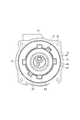
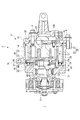
- FIG. 1 It is a longitudinal section of a scroll compressor concerning a 1st embodiment. It is the figure which looked at the front housing of a scroll compressor from the front.
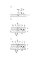
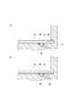
- the floating amount control mechanism which concerns on 1st Embodiment is shown, (a) is a figure which shows a control pin and the control hole formed in a thrust plate, (b) shows the state where the floating amount of a thrust plate is zero, (c) ) Shows a state where the floating amount of the thrust plate is maximum.
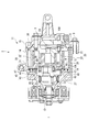
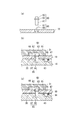
- the floating amount control mechanism which concerns on 2nd Embodiment is shown, (a) is a figure which shows a control pin and the control hole formed in a thrust plate, (b) shows the state where the floating amount of a thrust plate is zero, (c) ) Shows a state where the floating amount of the thrust plate is maximum. It is a longitudinal cross-sectional view of the scroll compressor concerning a 3rd embodiment.
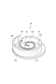
- the floating amount control mechanism which concerns on 3rd Embodiment is shown, (a) shows the state in which the floating amount of a thrust plate is zero, (b) has shown the state in which the floating amount of a thrust plate is the largest. It is a perspective view of a revolving scroll.
- the horizontal-type scroll compressor (hereinafter referred to as a compressor) 1 in the present embodiment is disposed inside the housing 11 and the housing 11 as shown in FIG. 1 and compresses the refrigerant gas taken in the housing 11
- a scroll compression mechanism (hereinafter, compression mechanism) 12 and a main shaft 13 for driving the compression mechanism 12 are provided as main components.
- the compressor 1 compresses a refrigerant and supplies it to, for example, a refrigerant circuit of an air conditioner for a vehicle.
- the compressor 1 has a configuration capable of avoiding generation of an excessive pressing force on the tip of the lap while adopting the turning back pressure control.
- the configuration of the compressor 1 will be described.
- the housing 11 includes a front housing 14 and a rear housing 15. On the circumference of the front housing 14 and the rear housing 15, flanges for clamping are formed at a plurality of locations, and are integrally clamped and fixed by a fastening member 9.
- the compression mechanism 12 described below is accommodated in an accommodation space formed by combining the front housing 14 and the rear housing 15.
- the side on which the front housing 14 is provided is defined as front
- the side on which the rear housing 15 is provided is defined as rear.
- the compression mechanism 12 includes a fixed scroll 20 fixed to the housing 11 and a orbiting scroll 30 that revolves around the fixed scroll 20. Further, the inside of the housing 11 is divided by the compression mechanism 12 into a low pressure chamber 10A and a high pressure chamber 10B.
- the fixed scroll 20 is provided such that its central axis coincides with the central axis L of the main shaft 13, and forms the orbiting scroll 30 and the compression chamber PR.
- the fixed scroll 20 includes a fixed end plate 21 supported by the rear housing 15 and a spiral wrap 22 erected from one surface of the fixed end plate 21. A discharge port 23 penetrating in the axial direction is formed at the center of the fixed end plate 21.
- the high pressure and high temperature refrigerant gas compressed in the compression chamber PR passes through the discharge port 23 and flows into the high pressure chamber 10B.
- the refrigerant gas includes the sliding surfaces of the fixed scroll 20 and the orbiting scroll 30, and lubricating oil for lubricating the bearings.
- a tip seal 28 is provided on the tip end surface of the wrap 22 in order to secure a seal between the tip end surface and the pivoting end plate 31 of the opposing orbiting scroll 30 opposed to the tip end surface.
- the tip seal 28 slides in contact with the pivoting end plate 31 of the orbiting scroll 30 via lubricating oil, thereby sealing a gap formed between the tip end face of the wrap 22 and the pivoting end plate 31. ing.
- a gap necessary to form an oil film of lubricating oil is formed between the tip end surface and the pivoting end plate 31.
- the wrap 22 can be formed with an abradable coating as a sealing material on its tip surface.
- the abradable coating wears away when it contacts the pivot end plate 31 of the orbiting scroll 30 which is the opposite side. Therefore, the gap between the tip end face of the wrap 22 and the pivoting end plate 31 can be kept to a minimum.
- the dimensional tolerance required for the member related to the floating amount restriction of the orbiting scroll 30 can be relaxed by the wear of the abradable coating.
- a regulating pin 60 described later, a thrust plate 19 provided with a regulating hole 65 into which the regulating pin 60 is inserted, and the like correspond.
- the material of the abradable coating is not limited, and can be selected from metal materials, resin materials and ceramic materials.
- An abradable coating can also be provided on the wrap 32 of the orbiting scroll 30.
- the orbiting scroll 30 includes a disc-shaped orbiting end plate 31 and a spiral wrap 32 erected from one surface of the orbiting end plate 31.
- a boss 27 is provided on the back surface of the orbiting end plate 31 of the orbiting scroll 30, and an eccentric bush 17 is assembled to the boss 27 via a bearing.
- An eccentric pin 18 is fitted inside the eccentric bush 17.
- An oldham joint (not shown) is provided between the orbiting scroll 30 and the main shaft 13 so that the orbiting scroll 30 does not rotate while revolving, and a pin-ring type anti-rotation mechanism is provided.
- the anti-rotation mechanism is provided at four places indicated by P1 shown in FIG. 2, and the configuration will be described in the second embodiment.
- a tip seal 38 is provided on the tip end face of the wrap 32 like the tip end face of the wrap 22, and an oil film of lubricating oil is formed between the tip seal 38 and the fixed end plate 21.
- the fixed scroll 20 and the orbiting scroll 30 are offset from each other by a predetermined amount so that there is a slight gap in the wrap height direction between the tip surface and the bottom surface of the wraps 22 and 32 meshed with 180 degrees out of phase.
- a pair of compression chambers PR formed by the end plates 21 and 31 and the wraps 22 and 32 are formed symmetrically with respect to the scroll center between the scrolls 20 and 30.
- the compression chamber PR is gradually moved to the inner circumferential side while reducing its volume. Then, the refrigerant gas is maximally compressed at the center of the spiral.
- the compression mechanism 12 reduces the volume of the compression space formed between the scrolls 20 and 30 also in the height direction of the wrap in the middle of the spiral, and is referred to as 3D scroll (registered trademark). Therefore, in both the fixed scroll 20 and the orbiting scroll 30, the height of the wrap is made lower on the inner peripheral side than the outer peripheral side, and the other end plate facing the step-like wrap is inner than the outer peripheral side. It is made to project on the inner side of the end plate on the circumferential side.
- a step portion 32 ⁇ / b> C is formed between the inner circumferential wrap 32 ⁇ / b> A and the outer circumferential wrap 32 ⁇ / b> B of the orbiting scroll 30.
- the outer circumferential wrap 32B rises from the inner circumferential wrap 32A, and the outer circumferential wrap 32B is taller.
- the end plate 31 includes the inner bottom 31A and the outer bottom 31B, and the step 31C is formed between the two, so that the inner bottom 31A is taller.
- the fixed scroll 20 also has the same structure as that of the orbiting scroll.
- step difference of one step was shown here, the level
- An annular thrust plate 19 is provided in front of the orbiting scroll 30 so as to approach and face the orbiting end plate 31.
- the thrust plate 19 is made of a wear resistant material, and is disposed between the pivoting end plate 31 and the front housing 14 facing the pivoting end plate 31 and supports the thrust load from the orbiting scroll 30.
- the thrust plate 19 functions as a thrust slide bearing with respect to the orbiting scroll 30, and the orbiting scroll 30 slides on the thrust plate 19 while the compressor 1 is in operation.
- the thrust plate 19 in the present embodiment has a function of applying a back pressure to the orbiting scroll 30 in addition to functioning as a thrust slide bearing as described above.
- the movement of the thrust plate 19 in the circumferential direction is restricted, but the movement in the forward direction is not restricted in order to realize the back pressure application function, and the floating relative to the front housing 14 is enabled. ing.
- the scroll compressor 1 has the following configuration in order to apply a back pressure to the orbiting scroll 30 via the thrust plate 19.
- an inner seal 46 and an outer seal 47 made of an elastic material are provided between the thrust plate 19 and the front housing 14 at intervals in the radial direction.
- An annular recess 44 is formed between the inner seal 46 and the outer seal 47 along the circumferential direction of the front housing 14 (thrust plate 19).
- a communication passage 43 communicating with the recess 44 is annularly formed in the front housing 14.
- the recess 44 and the communication passage 43 are collectively referred to as a pressure pocket 45.
- the communication passage 43 and the high pressure chamber 10B communicate with each other through the high pressure side passage 41 having an opening area A1.
- the high pressure refrigerant gas discharged into the high pressure chamber 10 B passes through the high pressure side flow passage 41 and flows into the pressure pocket 45.
- the inner sealing body 46 is provided as close to the center as possible except for P1 provided with the rotation prevention mechanism and P2 provided with the flying height restriction mechanism, and the opening area of the recess 44 is obtained. It is. Thereby, the back pressure applied to the orbiting scroll 30 can be secured.
- a low pressure side flow passage 42 having an opening area A2 is in communication with the communication passage 43, and the other end of the low pressure side flow passage 42 is in communication with the low pressure chamber 10A. Therefore, the high pressure and high temperature refrigerant gas flowing into the pressure pocket 45 from the high pressure side flow passage 41 flows into the low pressure chamber 10A through the low pressure side flow passage 42 after passing through the pressure pocket 45.
- the refrigerant gas contains lubricating oil, and the low pressure side flow passage 42 functions exclusively as a passage for returning the lubricating oil to the low pressure chamber 10A.
- the opening area A2 of the low pressure side flow passage 42 is set to be smaller than the opening area A1 of the high pressure side flow passage 41 (A2 ⁇ A1). Therefore, the amount of refrigerant gas flowing out from the pressure pocket 45 into the low pressure chamber 10A is smaller than the amount flowing into the pressure pocket 45 from the high pressure side flow passage 41.
- the compressor 1 is provided with a mechanism that regulates the floating amount of the orbiting scroll 30.
- This mechanism regulates the floating amount of the orbiting scroll 30 by restricting the floating amount of the thrust plate 19 which floats the orbiting scroll 30 under the pressure of the refrigerant gas as described below.
- this mechanism is provided with a restriction pin 60 which penetrates the thrust plate 19 and whose front end side is fixed to the front housing 14.
- the restriction pin 60 includes a shaft 61 and a head 62 connected to the shaft 61 as components.
- the head portion 62 is formed to have a diameter larger than that of the shaft portion 61.
- a cylindrical air gap 35 is provided in the pivoting end plate 31 at a position corresponding to the restriction pin 60.
- the thrust plate 19 is provided with a restriction hole 65 which penetrates the front and back of the thrust plate 19 and into which the restriction pin 60 is inserted.
- the restriction hole 65 has a small diameter portion 66 having a diameter corresponding to the shaft portion 61 of the restriction pin 60 and a large diameter portion 67 having a diameter corresponding to the head 62 of the restriction pin 60.
- FIG. 3 (b) shows a state where the thrust plate 19 is not lifted (lift amount is zero) because the thrust plate 19 is not receiving back pressure
- FIG. 3 (c) is a thrust plate.
- the application of the back pressure to the surface 19 indicates that the floating amount of the thrust plate 19 is maximized.
- the thrust plate 19 floats when receiving a back pressure, but the step is the boundary portion between the small diameter portion 66 and the large diameter portion 67 of the control pin 60.
- the thrust plate 19 is restricted from rising above the locked position.
- FIGS. 3A, 3 B, and 3 C refer to one flying height regulation mechanism consisting of a pair of regulation pins 60 and regulation holes 65, but in the present embodiment, two or more are used. It is possible to provide a flying height regulation mechanism of For example, a flying height restriction mechanism can be provided at each of the positions indicated by P2 in FIG. In FIG. 2, two P2s are provided at symmetrical positions.
- the pressure pocket 45 is sealed by the thrust plate 19, the inner and outer sealing bodies 46 and 47, and the front housing 14 except for the connection portion with the high pressure side flow passage 41 and the low pressure side flow passage 42.
- the high pressure refrigerant gas that has flowed into the pressure pocket 45 is a back pressure that pushes the orbiting scroll 30 toward the fixed scroll 20 via the thrust plate 19 in the process of flowing in the pressure pocket 45 along the circumferential direction. Grant Since the opening area A2 of the low pressure side flow passage 42 is smaller than the opening area A1 of the high pressure side flow passage 41, a predetermined pressure is loaded on the pressure pocket 45.
- the force pressing the orbiting scroll 30 depends on the pressure of the refrigerant gas discharged to the high pressure chamber 10B.
- the refrigerant gas having passed through the pressure pocket 45 is sucked into the low pressure chamber 10A from the low pressure side flow passage 42, but the lubricating oil contained in the refrigerant gas is returned to the low pressure chamber 10A.
- lubricating oil contained in refrigerant gas can also be made to flow into pressure pocket 45.
- the oil separation chamber is provided on the high pressure chamber 10B side, and the high pressure side flow passage 41 is provided on the bottom of the oil separation chamber.
- the lubricating oil separated in the oil separation chamber flows to the bottom of the oil separation chamber by its own weight, passes through the high pressure side flow passage 41, and flows into the pressure pocket 45.
- Pressure is applied to the lubricating oil from the refrigerant gas in the high pressure chamber 10B. Therefore, the pressing force of the lubricating oil on the thrust plate 19 depends on the pressure of the refrigerant gas discharged from the compression chamber PR.
- the lubricating oil is returned to the low pressure chamber 10A via the low pressure side flow passage 42.
- the compressor 1 can restrict the floating amount of the orbiting scroll 30 by the floating amount restricting mechanism by the restricting pin 60 and the restricting hole 65 during high-performance operation, so that the tip end faces of the wraps 22 and 32 are the opposite end plates It is possible to avoid being pressed by excessive force on 31 and 21. Therefore, the compressor 1 can ensure reliability against a defect such as burning of the tips of the wraps 22 and 32 while performing back pressure control.
- the compressor 1 realizes the regulation of the floating amount of the orbiting scroll 30 by regulating the floating amount of the thrust plate 19.
- the orbiting scroll 30 with the same flying height regulation mechanism as this embodiment, but since the sliding with the regulating pin 60 inevitably occurs as the orbiting motion of the orbiting scroll 30 occurs, There is a concern that problems such as galling and burn-in will occur between the two.
- the thrust plate 19 does not move except floating as in the present embodiment, when the thrust plate 19 is provided with the mechanism, it is possible to ensure the reliability against these problems.
- the rotation preventing mechanism can prevent the thrust plate 19 from tilting and can contribute to the thrust plate 19 floating stably.
- FIGS. 4 and 5A, 5B, and 5C a pin for preventing rotation of the orbiting scroll 30 originally provided in the scroll-type compressor 2 is used instead of the regulating pin 60 of the flying height regulating mechanism.
- the compressor 2 is otherwise provided with the same configuration as the compressor 1, the same components as the reference numerals used in the first embodiment are shown in FIG. 4 and FIGS. 5 (a), 5 (b) and (5).
- the same reference numerals as in FIGS. 1 to 3 (a), 3 (b) and 3 (c) are attached to c), and in the following, the compressor 2 is omitted focusing on the differences from the compressor 1.
- the compressor 2 includes an anti-rotation mechanism for preventing rotation of the orbiting scroll 30.
- This anti-rotation mechanism is provided at a position indicated by P1 in FIG. 2, and in this embodiment, a pin-ring type anti-rotation mechanism is employed.
- the anti-rotation mechanism includes a restriction pin (anti-rotation pin) 60 fixed to the front housing 14 and an anti-rotation ring 68 provided on the orbiting scroll 30.
- the restriction pin 60 is different from the first embodiment in that it includes an anti-rotation pin portion 63 in addition to the shaft portion 61 and the head 62 as shown in FIG. 5A.
- the thrust plate 19 is provided with a restriction hole 65 which penetrates the front and back and into which the restriction pin 60 is inserted.
- the restriction hole 65 is formed into the small diameter portion 66 and the large diameter portion 67 in the same manner as in the first embodiment.
- the anti-rotation ring 68 is fitted in a cylindrical air gap 35 formed in the thrust surface on the back side of the turning end plate 31 of the turning scroll 30.
- the restricting pin 60 is inserted into the restricting hole 65 of the thrust plate 19 as shown in FIGS. 5B and 5C, and the tip end side is fixed to the front housing 14.
- the anti-rotation pin portion 63 is provided to project from the surface of the thrust plate 19 into the inside of the air gap 35.
- FIG. 5 (b) shows a state where the floating amount of the thrust plate 19 is zero
- FIG. 5 (c) shows a state where the floating amount of the thrust plate 19 is maximum.
- the anti-rotation pin portion 63 of the restriction pin 60 revolves along the inner wall surface of the anti-rotation ring 68 to prevent the rotation of the orbiting scroll 30. A revolving motion is made possible.
- the compressor 2 exerts the following effects in addition to having the same operation and effect as the compressor 1 of the first embodiment. Since the floating amount of the orbiting scroll 30 is restricted utilizing the anti-rotation pins provided in the scroll compressor, it is not necessary to provide a dedicated restriction pin for restricting the floating amount. Therefore, since the compressor 2 can reduce the number of parts compared to the first embodiment, it contributes to cost reduction. In addition, since a portion where the dedicated restriction pin 60 penetrates the thrust plate 19 can not receive the back pressure, the area of the thrust plate 19 receiving the back pressure is reduced when the dedicated restriction pin 60 is provided. On the other hand, if the anti-rotation pin is used like the compressor 2, the back pressure area is not reduced by the dedicated restriction pin 60, so the back pressure area can be expanded compared to the first embodiment. it can.
- a compressor 3 according to a third embodiment will be described based on FIG. 6 and FIGS. 7 (a) and 7 (b).
- the floating amount of the orbiting scroll 30 via the thrust plate 19 is regulated by locking the thrust plate 19 to the housing.
- the compressor 3 has the configuration necessary for that, but the basic configuration as a scroll compressor is the same as the compressor 1. Therefore, the same components as those of the compressor 1 are given the same reference numerals as in FIGS. 1 to 3 (a), (b) and (c) in FIGS. 6 and 7 (a) and (b). Now, the compressor 3 will be described focusing on differences from the compressor 1.
- the compressor 3 enlarges the diameter of the thrust plate 19 to such an extent that it interferes with the inner wall surface of the front housing 14 as shown in FIGS. 6 and 7A and 7B.
- a restriction groove 69 which recedes in the thickness direction from the inner wall surface is formed.
- the restriction groove 69 is formed in a ring shape continuously in the circumferential direction of the inner wall surface.
- FIG. 7A shows a state where the floating amount of the thrust plate 19 is zero
- FIG. 7B shows a state where the floating amount of the thrust plate 19 is maximum.
- the thrust plate 19 floats when receiving a back pressure
- the thrust plate 19 is engaged with the upper wall of the restriction groove 69. Is restricted to rise above the locked position.
- the compressor 3 can regulate the floating amount of the orbiting scroll 30 by locking the thrust plate 19 and the front housing 14.
- the restriction groove 69 the dimension (depth) receding from the inner wall surface and the dimension (width) in the axial direction are arbitrary as long as the restriction of the floating amount described above can be realized. Further, here, although it is assumed that the restriction groove 69 is continuous to the whole area in the circumferential direction and the whole area of the peripheral edge of the thrust plate 19 is inserted inside the restriction groove 69, the restriction of the flying height described above is realized If possible, the restriction groove 69 may be provided intermittently in the circumferential direction, and the enlarged portion of the diameter of the thrust plate 19 inserted into the restriction groove 69 may be intermittently provided accordingly.
- the compressor 3 has the following effects in addition to the same effects as the compressor 1 of the first embodiment. Since the compressor 3 regulates the floating amount of the orbiting scroll 30 by locking the thrust plate 19 and the front housing 14, there is no need to provide a dedicated restriction pin for regulating the floating amount. Therefore, compared with the first embodiment, the compressor 3 can achieve cost reduction by reducing the number of parts. Further, since the compressor 3 does not need to have the dedicated restriction pin 60, the back pressure area can be expanded as compared with the first embodiment, as in the second embodiment. In addition, since the compressor 3 locks the peripheral edge of the thrust plate 19 over the entire circumference by the restriction groove 69, it is possible to reduce the variation in the floating amount in the circumferential direction when the thrust plate 19 reaches the maximum floating amount. .
- the thrust plate 19 is locked to the housing, it is important to precisely form the regulating groove 69 in order to strictly control the floating amount of the orbiting scroll 30. Since the restriction groove 69 shown above is located at the bottom of the front housing 14 as can be seen from FIG. 6, it is difficult to machine the restriction groove 69 with high accuracy. Therefore, as shown in FIG. 6, if the housing is divided into separate members by the boundary line CL corresponding to the restriction groove 69, the restriction groove 69 can be easily processed.
- the fixed scroll 20 is integrally configured with a portion corresponding to the front housing 14 positioned on the right side of the boundary line CL in the drawing.
- this integral configuration and a portion corresponding to the front housing 14 positioned on the left side of the boundary line CL in the drawing are butted at the boundary line CL. If the third embodiment is applied to the scroll compressor referred to as this three-piece type, the restricting groove 69 can be formed easily and precisely.
- the present invention only needs to have a portion where the orbiting scroll 30 is pressed. Therefore, although the recess 44 is provided in the front housing 14 in the present embodiment, the recess 44 may be provided in the thrust plate 19. However, since the front side of the pivoting end plate 31 may have a complicated shape in relation to the peripheral members, the recess 44 can be formed on the same plane by providing the thrust plate 19. Then, the orbiting scroll can be pressed with an equal force.
Abstract
A scroll compressor is provided with: a scroll compression mechanism having an orbiting scroll (30), a stationary scroll (20), and a thrust plate (19) for supporting the load of the orbiting scroll in the thrust direction; a back-pressure application mechanism for applying, as back pressure, a refrigerant gas compressed by the scroll compression mechanism to the rear surface of the thrust plate (19); and a lift amount restriction mechanism for restricting the amount of lift of the thrust plate (19) caused by the back pressure. The lift amount restriction mechanism comprises a restriction pin (60) provided with: a shaft (61) which passes through the thrust plate (19) and which has a front end portion affixed to a front housing (14); and a head (62) which has a larger diameter than the shaft (61), and the lift amount restriction mechanism allows the thrust plate (19) to be engaged with the head (62) to restrict the amount of lift of the thrust plate (19).
Description
本発明は、スクロール圧縮機に関する。
The present invention relates to a scroll compressor.
車両用空気調和機に用いられるスクロール型の圧縮機は、固定スクロールと旋回スクロールとを備える。固定スクロールおよび旋回スクロールは、それぞれ円板状の端板の一面側に渦巻状のラップが一体に形成されたものである。この固定スクロールと旋回スクロールを、ラップ同士を噛み合わせた状態で対向させて固定スクロールに対して旋回スクロールを公転旋回運動させ、双方のラップの間に形成される圧縮空間を外周側から内周側に移動させつつその容積を減少させることで、冷媒の圧縮を行なう。なお、固定スクロールと旋回スクロールを含む、冷媒の圧縮に係る機構をスクロール圧縮機構ということがある。
A scroll-type compressor used for a vehicle air conditioner includes a fixed scroll and a revolving scroll. The fixed scroll and the orbiting scroll each have a spiral wrap integrally formed on one side of a disk-shaped end plate. The fixed scroll and the orbiting scroll are opposed to each other in a state in which the wraps are engaged with each other, and the orbiting scroll is revolved with respect to the fixed scroll, and the compression space formed between both wraps The refrigerant is compressed by reducing its volume while moving it. The mechanism related to the compression of the refrigerant including the fixed scroll and the orbiting scroll may be referred to as a scroll compression mechanism.
スクロール圧縮機の作動時には、旋回スクロールと固定スクロールは互いに離れる向きに圧縮された冷媒から力を受けて、旋回スクロールが軸方向に移動する。そうすると、双方のスクロールのラップの先端面(歯先)と相手側の端板との間に隙間が形成され、その隙間から冷媒が漏れてしまうために圧縮機の性能が低下し得る。
そこで、例えば特許文献1に開示されるように、圧縮機の作動時に旋回スクロールの移動を防止するために、旋回スクロールの背面に圧縮された冷媒を作用させて旋回スクロールを浮上させることで、常にラップの先端面が相手側の端板に接するように制御することが提案されている。なお、この制御を、旋回背圧制御ということがある。 During operation of the scroll compressor, the orbiting scroll and the stationary scroll move axially in response to a force from the refrigerant compressed away from each other. Then, a gap is formed between the tip surfaces (tooth tips) of the wraps of both scrolls and the opposite end plate, and the refrigerant may leak from the gap, which may degrade the performance of the compressor.
Therefore, for example, as disclosed inPatent Document 1, in order to prevent the movement of the orbiting scroll at the time of operation of the compressor, the compressed refrigerant is allowed to act on the back surface of the orbiting scroll to float the orbiting scroll at all times. It has been proposed to control so that the tip end face of the wrap contacts the other end plate. In addition, this control may be called turning back pressure control.
そこで、例えば特許文献1に開示されるように、圧縮機の作動時に旋回スクロールの移動を防止するために、旋回スクロールの背面に圧縮された冷媒を作用させて旋回スクロールを浮上させることで、常にラップの先端面が相手側の端板に接するように制御することが提案されている。なお、この制御を、旋回背圧制御ということがある。 During operation of the scroll compressor, the orbiting scroll and the stationary scroll move axially in response to a force from the refrigerant compressed away from each other. Then, a gap is formed between the tip surfaces (tooth tips) of the wraps of both scrolls and the opposite end plate, and the refrigerant may leak from the gap, which may degrade the performance of the compressor.
Therefore, for example, as disclosed in
ところが、旋回スクロールを浮上させた場合には、旋回スクロールからのスラスト荷重をラップの歯先が受け持つことになる。そうすると、背圧に付与される圧力が過大になると、相手側の端板に対するラップの歯先の押し付け力が過大となり、ラップの歯先が端板に焼き付いたり、破損したりするおそれがある。
本発明は、このような課題に基づいてなされたもので、旋回背圧制御を採用しつつ、ラップの歯先に過大な押し付け力が生ずるのを回避できるスクロール圧縮機を提供することを目的とする。 However, when the orbiting scroll is lifted, the tip of the lap receives the thrust load from the orbiting scroll. In this case, if the pressure applied to the back pressure becomes excessive, the pressing force of the tip of the wrap against the end plate on the opposite side becomes excessive, and the tip of the wrap may be seized or damaged in the end plate.
The present invention has been made on the basis of such problems, and it is an object of the present invention to provide a scroll compressor capable of avoiding generation of an excessive pressing force on the tip of a lap while adopting turning back pressure control. Do.
かかる目的のもとなされた本発明のスクロール圧縮機は、スクロール圧縮機構と、背圧付与機構と、浮上量規制機構と、スクロール圧縮機構、背圧付与機構及び浮上量規制機構と、を収容するハウジングとを備える。
本発明のスクロール圧縮機構は、旋回スクロールと、旋回スクロールと対向することで冷媒ガスを圧縮する圧縮室を形成する固定スクロールと、旋回スクロールのスラスト方向の荷重を支持するスラスト板と、を有する。
背圧付与機構は、スクロール圧縮機構で圧縮された冷媒ガスを、スラスト板の背面に背圧として作用させる。
浮上量規制機構は、背圧に基づくスラスト板の浮上量を規制する。 The scroll compressor according to the present invention, which has been made for this purpose, accommodates a scroll compression mechanism, a back pressure application mechanism, a flying height restriction mechanism, a scroll compression mechanism, a back pressure application mechanism, and a flying height restriction mechanism. And a housing.
The scroll compression mechanism according to the present invention has a orbiting scroll, a fixed scroll forming a compression chamber that compresses a refrigerant gas by facing the orbiting scroll, and a thrust plate that supports a load in the thrust scroll direction of the orbiting scroll.
The back pressure application mechanism causes the refrigerant gas compressed by the scroll compression mechanism to act on the back surface of the thrust plate as a back pressure.
The flying height regulation mechanism regulates the flying height of the thrust plate based on the back pressure.
本発明のスクロール圧縮機は、背圧付与機構が、スクロール圧縮機構で圧縮された冷媒ガスをスラスト板の背面に背圧として作用させることにより、スラスト板を浮上させ、これにより旋回スクロールを浮上させる。そして、本発明のスクロール圧縮機は、浮上量規制機構によるスラスト板の浮上量の規制を介して、旋回スクロールの浮上量を規制できるので、ラップの歯先に過大な押し付け力が生ずるのを回避できる。
In the scroll compressor according to the present invention, the back pressure application mechanism causes the refrigerant gas compressed by the scroll compression mechanism to act on the back surface of the thrust plate as a back pressure, thereby causing the thrust plate to rise and thereby raise the orbiting scroll. . And since the scroll compressor of the present invention can regulate the floating amount of the orbiting scroll through the control of the floating amount of the thrust plate by the floating amount restricting mechanism, it avoids the occurrence of an excessive pressing force on the wrap tips. it can.
本発明のスクロール圧縮機において、浮上量規制機構は、スラスト板を貫通するとともに、先端部分がハウジングに固定される軸部と、軸部に連なり、軸部よりも径の大きな頭部と、を備え、スラスト板を頭部に係止させることで浮上量を規制する規制ピンを備えることができる。この頭部は、スラスト板を貫通し、規制ピンが挿入される規制孔の段差に係止させることができる。
この規制ピンとして、旋回スクロールの自転を防止するピン-リング式の自転防止機構を備え、この自転防止ピンを規制ピンとして機能させることができる。
本発明のスクロール圧縮機において、浮上量規制機構は、スラスト板の周縁が、ハウジングの内周壁に係止されることで、浮上量を規制することもできる。 In the scroll compressor according to the present invention, the flying height restriction mechanism penetrates the thrust plate, the shaft portion whose tip portion is fixed to the housing, and the head portion connected to the shaft portion and having a diameter larger than that of the shaft portion. A control pin can be provided to limit the floating amount by locking the thrust plate to the head. The head passes through the thrust plate and can be engaged with the step of the restriction hole into which the restriction pin is inserted.
As the restriction pin, a pin-ring type anti-rotation mechanism for preventing rotation of the orbiting scroll can be provided, and this rotation prevention pin can be functioned as a restriction pin.
In the scroll compressor of the present invention, the flying height regulating mechanism can also regulate the flying height by the peripheral edge of the thrust plate being locked to the inner circumferential wall of the housing.
本発明のスクロール圧縮機において、旋回スクロールが備えるラップと固定スクロールが備えるラップの一方又は双方の先端面に、アブレイダブルコーティングが設けられていることが好ましい。アブレイダブルコーティングを設けることにより、旋回スクロールの浮上量規制に関係する部材に要求される寸法公差を緩和することができる。
In the scroll compressor according to the present invention, it is preferable that an abradable coating is provided on the tip surface of one or both of the wrap provided on the orbiting scroll and the wrap provided on the fixed scroll. By providing the abradable coating, dimensional tolerances required for members related to the flying height regulation of the orbiting scroll can be relaxed.
本発明によれば、旋回背圧制御を採用しつつ、ラップの歯先に過大な押し付け力が生ずるのを回避できるスクロール圧縮機を提供できる。
According to the present invention, it is possible to provide a scroll compressor capable of avoiding generation of an excessive pressing force on the tip of a lap while adopting turning back pressure control.
以下、添付図面に示す実施の形態に基づいてこの発明を詳細に説明する。
[第1実施形態]
本実施形態における横置き型のスクロール圧縮機(以下、圧縮機)1は、図1に示すように、ハウジング11と、ハウジング11の内部に配置され、ハウジング11内に取り込まれた冷媒ガスを圧縮するスクロール圧縮機構(以下、圧縮機構)12と、圧縮機構12を駆動する主軸13とを主たる構成要素として備えている。この圧縮機1は、冷媒を圧縮して例えば車両用空気調和機の冷媒回路に供給する。
圧縮機1は、旋回背圧制御を採用しつつ、ラップの歯先に過大な押し付け力が生ずるのを回避できる構成を備えている。以下、圧縮機1の構成を説明する。 Hereinafter, the present invention will be described in detail based on the embodiment shown in the attached drawings.
First Embodiment
The horizontal-type scroll compressor (hereinafter referred to as a compressor) 1 in the present embodiment is disposed inside thehousing 11 and the housing 11 as shown in FIG. 1 and compresses the refrigerant gas taken in the housing 11 A scroll compression mechanism (hereinafter, compression mechanism) 12 and a main shaft 13 for driving the compression mechanism 12 are provided as main components. The compressor 1 compresses a refrigerant and supplies it to, for example, a refrigerant circuit of an air conditioner for a vehicle.
Thecompressor 1 has a configuration capable of avoiding generation of an excessive pressing force on the tip of the lap while adopting the turning back pressure control. Hereinafter, the configuration of the compressor 1 will be described.
[第1実施形態]
本実施形態における横置き型のスクロール圧縮機(以下、圧縮機)1は、図1に示すように、ハウジング11と、ハウジング11の内部に配置され、ハウジング11内に取り込まれた冷媒ガスを圧縮するスクロール圧縮機構(以下、圧縮機構)12と、圧縮機構12を駆動する主軸13とを主たる構成要素として備えている。この圧縮機1は、冷媒を圧縮して例えば車両用空気調和機の冷媒回路に供給する。
圧縮機1は、旋回背圧制御を採用しつつ、ラップの歯先に過大な押し付け力が生ずるのを回避できる構成を備えている。以下、圧縮機1の構成を説明する。 Hereinafter, the present invention will be described in detail based on the embodiment shown in the attached drawings.
First Embodiment
The horizontal-type scroll compressor (hereinafter referred to as a compressor) 1 in the present embodiment is disposed inside the
The
[ハウジング11]
ハウジング11は、フロントハウジング14とリアハウジング15とを備える。フロントハウジング14とリアハウジング15の円周上には、複数箇所に締め付け用のフランジが形成され、締結部材9により一体的に締め付け固定されている。
フロントハウジング14とリアハウジング15が組み合わさって形成される収容空間に、以下説明する圧縮機構12が収容される。なお、圧縮機1において、フロントハウジング14が設けられている側を前、リアハウジング15が設けられる側を後と定義する。 [Housing 11]
Thehousing 11 includes a front housing 14 and a rear housing 15. On the circumference of the front housing 14 and the rear housing 15, flanges for clamping are formed at a plurality of locations, and are integrally clamped and fixed by a fastening member 9.
Thecompression mechanism 12 described below is accommodated in an accommodation space formed by combining the front housing 14 and the rear housing 15. In the compressor 1, the side on which the front housing 14 is provided is defined as front, and the side on which the rear housing 15 is provided is defined as rear.
ハウジング11は、フロントハウジング14とリアハウジング15とを備える。フロントハウジング14とリアハウジング15の円周上には、複数箇所に締め付け用のフランジが形成され、締結部材9により一体的に締め付け固定されている。
フロントハウジング14とリアハウジング15が組み合わさって形成される収容空間に、以下説明する圧縮機構12が収容される。なお、圧縮機1において、フロントハウジング14が設けられている側を前、リアハウジング15が設けられる側を後と定義する。 [Housing 11]
The
The
[圧縮機構12]
圧縮機構12は、ハウジング11に対して固定される固定スクロール20と、固定スクロール20に対して公転旋回運動する旋回スクロール30とを備えている。また、ハウジング11の内部は、圧縮機構12により低圧室10Aと高圧室10Bに仕切られている。
固定スクロール20は、その中心軸が主軸13の中心軸Lと一致するように設けられ、旋回スクロール30と圧縮室PRを形成する。
固定スクロール20は、リアハウジング15に支持されている固定端板21と、固定端板21の一方の面から立設する渦巻状のラップ22とを備えている。
固定端板21の中心部には、軸方向に貫通する吐出ポート23が形成されている。圧縮室PRで圧縮された高圧高温の冷媒ガスは、吐出ポート23を通過して高圧室10Bに流入する。この冷媒ガスには、固定スクロール20と旋回スクロール30の摺動面、軸受の潤滑を行うための潤滑油が含まれている。
ラップ22の先端面には、先端面と対向する相手側の旋回スクロール30の旋回端板31との間のシール性を確保するためにチップシール28が設けられている。チップシール28は、潤滑油を介して旋回スクロール30の旋回端板31と接触して摺動されることで、ラップ22の先端面と旋回端板31との間に形成される隙間をシールしている。先端面と旋回端板31の間には、潤滑油の油膜を形成するために必要な隙間が形成されている。
ラップ22は、その先端面にアブレイダブルコーティング(Abradable Coating)をシ
ール材として形成することができる。
このアブレイダブルコーティングは、相手側である旋回スクロール30の旋回端板31に接触すると磨滅する。したがって、ラップ22の先端面と旋回端板31の間の隙間を最小に保持することができる。また、アブレイダブルコーティングが磨滅する分だけ、旋回スクロール30の浮上量規制に関係する部材に要求される寸法公差を緩和することができる。浮上量規制に関係する部材としては、後述する規制ピン60、規制ピン60が挿入される規制孔65を備えるスラスト板19などが該当する。
アブレイダブルコーティングの材質は限定されるものでなく、金属材料、樹脂材料及びセラミックス材料から選択することができる。アブレイダブルコーティングは、旋回スクロール30のラップ32にも設けることができる。 [Compression mechanism 12]
Thecompression mechanism 12 includes a fixed scroll 20 fixed to the housing 11 and a orbiting scroll 30 that revolves around the fixed scroll 20. Further, the inside of the housing 11 is divided by the compression mechanism 12 into a low pressure chamber 10A and a high pressure chamber 10B.
Thefixed scroll 20 is provided such that its central axis coincides with the central axis L of the main shaft 13, and forms the orbiting scroll 30 and the compression chamber PR.
Thefixed scroll 20 includes a fixed end plate 21 supported by the rear housing 15 and a spiral wrap 22 erected from one surface of the fixed end plate 21.
Adischarge port 23 penetrating in the axial direction is formed at the center of the fixed end plate 21. The high pressure and high temperature refrigerant gas compressed in the compression chamber PR passes through the discharge port 23 and flows into the high pressure chamber 10B. The refrigerant gas includes the sliding surfaces of the fixed scroll 20 and the orbiting scroll 30, and lubricating oil for lubricating the bearings.
Atip seal 28 is provided on the tip end surface of the wrap 22 in order to secure a seal between the tip end surface and the pivoting end plate 31 of the opposing orbiting scroll 30 opposed to the tip end surface. The tip seal 28 slides in contact with the pivoting end plate 31 of the orbiting scroll 30 via lubricating oil, thereby sealing a gap formed between the tip end face of the wrap 22 and the pivoting end plate 31. ing. A gap necessary to form an oil film of lubricating oil is formed between the tip end surface and the pivoting end plate 31.
Thewrap 22 can be formed with an abradable coating as a sealing material on its tip surface.
The abradable coating wears away when it contacts thepivot end plate 31 of the orbiting scroll 30 which is the opposite side. Therefore, the gap between the tip end face of the wrap 22 and the pivoting end plate 31 can be kept to a minimum. In addition, the dimensional tolerance required for the member related to the floating amount restriction of the orbiting scroll 30 can be relaxed by the wear of the abradable coating. As a member related to the flying height regulation, a regulating pin 60 described later, a thrust plate 19 provided with a regulating hole 65 into which the regulating pin 60 is inserted, and the like correspond.
The material of the abradable coating is not limited, and can be selected from metal materials, resin materials and ceramic materials. An abradable coating can also be provided on thewrap 32 of the orbiting scroll 30.
圧縮機構12は、ハウジング11に対して固定される固定スクロール20と、固定スクロール20に対して公転旋回運動する旋回スクロール30とを備えている。また、ハウジング11の内部は、圧縮機構12により低圧室10Aと高圧室10Bに仕切られている。
固定スクロール20は、その中心軸が主軸13の中心軸Lと一致するように設けられ、旋回スクロール30と圧縮室PRを形成する。
固定スクロール20は、リアハウジング15に支持されている固定端板21と、固定端板21の一方の面から立設する渦巻状のラップ22とを備えている。
固定端板21の中心部には、軸方向に貫通する吐出ポート23が形成されている。圧縮室PRで圧縮された高圧高温の冷媒ガスは、吐出ポート23を通過して高圧室10Bに流入する。この冷媒ガスには、固定スクロール20と旋回スクロール30の摺動面、軸受の潤滑を行うための潤滑油が含まれている。
ラップ22の先端面には、先端面と対向する相手側の旋回スクロール30の旋回端板31との間のシール性を確保するためにチップシール28が設けられている。チップシール28は、潤滑油を介して旋回スクロール30の旋回端板31と接触して摺動されることで、ラップ22の先端面と旋回端板31との間に形成される隙間をシールしている。先端面と旋回端板31の間には、潤滑油の油膜を形成するために必要な隙間が形成されている。
ラップ22は、その先端面にアブレイダブルコーティング(Abradable Coating)をシ
ール材として形成することができる。
このアブレイダブルコーティングは、相手側である旋回スクロール30の旋回端板31に接触すると磨滅する。したがって、ラップ22の先端面と旋回端板31の間の隙間を最小に保持することができる。また、アブレイダブルコーティングが磨滅する分だけ、旋回スクロール30の浮上量規制に関係する部材に要求される寸法公差を緩和することができる。浮上量規制に関係する部材としては、後述する規制ピン60、規制ピン60が挿入される規制孔65を備えるスラスト板19などが該当する。
アブレイダブルコーティングの材質は限定されるものでなく、金属材料、樹脂材料及びセラミックス材料から選択することができる。アブレイダブルコーティングは、旋回スクロール30のラップ32にも設けることができる。 [Compression mechanism 12]
The
The
The
A
A
The
The abradable coating wears away when it contacts the
The material of the abradable coating is not limited, and can be selected from metal materials, resin materials and ceramic materials. An abradable coating can also be provided on the
旋回スクロール30は、円板状の旋回端板31と、旋回端板31の一方の面から立設する渦巻状のラップ32とを備えている。
旋回スクロール30の旋回端板31の背面には、ボス27が設けられるとともに、そのボス27に軸受を介して偏心ブッシュ17が組みつけられている。偏心ブッシュ17の内側には偏心ピン18が嵌められている。これにより旋回スクロール30が主軸13の軸心に偏心して結合されるので、主軸13が回転すると、旋回スクロール30は、主軸13の軸心から偏心距離を旋回半径として回転(公転)する。
旋回スクロール30が公転しつつも自転しないよう、旋回スクロール30と主軸13の間には図示を省略するオルダム継手が設けられるとともに、ピン-リング式の自転防止機構が設けられている。この自転防止機構は、図2に示されるP1で示される四か所に設けられるが、その構成については第2実施形態において説明する。
ラップ32の先端面には、ラップ22の先端面と同様に、チップシール38が設けられ、チップシール38と固定端板21の間には、潤滑油の油膜が形成されている。 The orbitingscroll 30 includes a disc-shaped orbiting end plate 31 and a spiral wrap 32 erected from one surface of the orbiting end plate 31.
Aboss 27 is provided on the back surface of the orbiting end plate 31 of the orbiting scroll 30, and an eccentric bush 17 is assembled to the boss 27 via a bearing. An eccentric pin 18 is fitted inside the eccentric bush 17. As a result, the orbiting scroll 30 is eccentrically coupled to the axis of the main shaft 13, so that when the main shaft 13 rotates, the orbiting scroll 30 rotates (revolutes) from the axis of the main shaft 13 with an eccentric distance as the orbiting radius.
An oldham joint (not shown) is provided between the orbitingscroll 30 and the main shaft 13 so that the orbiting scroll 30 does not rotate while revolving, and a pin-ring type anti-rotation mechanism is provided. The anti-rotation mechanism is provided at four places indicated by P1 shown in FIG. 2, and the configuration will be described in the second embodiment.
Atip seal 38 is provided on the tip end face of the wrap 32 like the tip end face of the wrap 22, and an oil film of lubricating oil is formed between the tip seal 38 and the fixed end plate 21.
旋回スクロール30の旋回端板31の背面には、ボス27が設けられるとともに、そのボス27に軸受を介して偏心ブッシュ17が組みつけられている。偏心ブッシュ17の内側には偏心ピン18が嵌められている。これにより旋回スクロール30が主軸13の軸心に偏心して結合されるので、主軸13が回転すると、旋回スクロール30は、主軸13の軸心から偏心距離を旋回半径として回転(公転)する。
旋回スクロール30が公転しつつも自転しないよう、旋回スクロール30と主軸13の間には図示を省略するオルダム継手が設けられるとともに、ピン-リング式の自転防止機構が設けられている。この自転防止機構は、図2に示されるP1で示される四か所に設けられるが、その構成については第2実施形態において説明する。
ラップ32の先端面には、ラップ22の先端面と同様に、チップシール38が設けられ、チップシール38と固定端板21の間には、潤滑油の油膜が形成されている。 The orbiting
A
An oldham joint (not shown) is provided between the orbiting
A
固定スクロール20と旋回スクロール30は、互いに所定量だけ偏心し、180度位相をずらして噛み合わされるラップ22,32の先端面とボトム面との間に僅かなラップ高さ方向の隙間を有するように組み付けられる。これによって、図1に示すように、双方のスクロール20,30の間には、端板21,31とラップ22,32とにより形成される一対の圧縮室PRがスクロール中心に対して対称に形成されるとともに、旋回スクロール30の旋回に伴って、圧縮室PRはその容積を減少させながら、次第に内周側に移動される。そして、渦巻きの中心部で冷媒ガスが最大に圧縮される。
The fixed scroll 20 and the orbiting scroll 30 are offset from each other by a predetermined amount so that there is a slight gap in the wrap height direction between the tip surface and the bottom surface of the wraps 22 and 32 meshed with 180 degrees out of phase. Assembled to Thus, as shown in FIG. 1, a pair of compression chambers PR formed by the end plates 21 and 31 and the wraps 22 and 32 are formed symmetrically with respect to the scroll center between the scrolls 20 and 30. At the same time, as the orbiting scroll 30 pivots, the compression chamber PR is gradually moved to the inner circumferential side while reducing its volume. Then, the refrigerant gas is maximally compressed at the center of the spiral.
この圧縮機構12は、双方のスクロール20,30間に形成される圧縮空間の容積を渦巻きの途中でラップの高さ方向にも減少させており、3Dスクロール(登録商標)と称されている。そのために、固定スクロール20および旋回スクロール30の双方において、ラップの高さを外周側よりも内周側で低くするとともに、その段差状のラップに対向する相手側の端板を外周側よりも内周側で、端板内面側に突出するようにしている。
The compression mechanism 12 reduces the volume of the compression space formed between the scrolls 20 and 30 also in the height direction of the wrap in the middle of the spiral, and is referred to as 3D scroll (registered trademark). Therefore, in both the fixed scroll 20 and the orbiting scroll 30, the height of the wrap is made lower on the inner peripheral side than the outer peripheral side, and the other end plate facing the step-like wrap is inner than the outer peripheral side. It is made to project on the inner side of the end plate on the circumferential side.
図8に示すように、旋回スクロール30の内周側ラップ32Aと外周側ラップ32Bとの間には、段差部32Cが形成されている。段差部32Cでは、内周側ラップ32Aから外周側ラップ32Bが立ち上がり、外周側ラップ32Bの方が背が高くなっている。一方、端板31は、内周側底部31Aと外周側底部31Bとを備え、両者の間に段差部31Cが形成されることで、内周側底部31Aの方が背が高くなっている。
なお、固定スクロール20も旋回スクロールと同様の構造を有している。
また、ここでは一段階の段差の例を示したが、二段階以上の段差を設けることもできる。 As shown in FIG. 8, astep portion 32 </ b> C is formed between the inner circumferential wrap 32 </ b> A and the outer circumferential wrap 32 </ b> B of the orbiting scroll 30. In the step portion 32C, the outer circumferential wrap 32B rises from the inner circumferential wrap 32A, and the outer circumferential wrap 32B is taller. On the other hand, the end plate 31 includes the inner bottom 31A and the outer bottom 31B, and the step 31C is formed between the two, so that the inner bottom 31A is taller.
The fixedscroll 20 also has the same structure as that of the orbiting scroll.
Moreover, although the example of the level | step difference of one step was shown here, the level | step difference of two or more steps can also be provided.
なお、固定スクロール20も旋回スクロールと同様の構造を有している。
また、ここでは一段階の段差の例を示したが、二段階以上の段差を設けることもできる。 As shown in FIG. 8, a
The fixed
Moreover, although the example of the level | step difference of one step was shown here, the level | step difference of two or more steps can also be provided.
[スラスト板19]
旋回スクロール30の前方には、旋回端板31に近接かつ対向するように、円環状のスラスト板19が設けられている。
スラスト板19は耐摩耗性材料からなり、旋回端板31と旋回端板31に対向するフロントハウジング14の間に配置されており、旋回スクロール30からのスラスト荷重を支持する。スラスト板19は、旋回スクロール30に対してスラスト滑り軸受として機能するものであり、圧縮機1が作動中には、旋回スクロール30がスラスト板19上を摺動するようになっている。
本実施形態におけるスラスト板19は、以上のようにスラスト滑り軸受として機能するのに加えて、旋回スクロール30に背圧を付与する機能を備える。スラスト板19は、周方向への移動は拘束されているが、背圧付与機能を実現するために、前方に向けた移動は拘束されておらず、フロントハウジング14に対して浮上が可能とされている。 [Thrust plate 19]
Anannular thrust plate 19 is provided in front of the orbiting scroll 30 so as to approach and face the orbiting end plate 31.
Thethrust plate 19 is made of a wear resistant material, and is disposed between the pivoting end plate 31 and the front housing 14 facing the pivoting end plate 31 and supports the thrust load from the orbiting scroll 30. The thrust plate 19 functions as a thrust slide bearing with respect to the orbiting scroll 30, and the orbiting scroll 30 slides on the thrust plate 19 while the compressor 1 is in operation.
Thethrust plate 19 in the present embodiment has a function of applying a back pressure to the orbiting scroll 30 in addition to functioning as a thrust slide bearing as described above. The movement of the thrust plate 19 in the circumferential direction is restricted, but the movement in the forward direction is not restricted in order to realize the back pressure application function, and the floating relative to the front housing 14 is enabled. ing.
旋回スクロール30の前方には、旋回端板31に近接かつ対向するように、円環状のスラスト板19が設けられている。
スラスト板19は耐摩耗性材料からなり、旋回端板31と旋回端板31に対向するフロントハウジング14の間に配置されており、旋回スクロール30からのスラスト荷重を支持する。スラスト板19は、旋回スクロール30に対してスラスト滑り軸受として機能するものであり、圧縮機1が作動中には、旋回スクロール30がスラスト板19上を摺動するようになっている。
本実施形態におけるスラスト板19は、以上のようにスラスト滑り軸受として機能するのに加えて、旋回スクロール30に背圧を付与する機能を備える。スラスト板19は、周方向への移動は拘束されているが、背圧付与機能を実現するために、前方に向けた移動は拘束されておらず、フロントハウジング14に対して浮上が可能とされている。 [Thrust plate 19]
An
The
The
[背圧付与機構]
スクロール圧縮機1は、スラスト板19を介して旋回スクロール30に背圧を付与するために、以下の構成を備えている。
スラスト板19とフロントハウジング14の間には、図2に示すように、それぞれ弾性素材からなる内側封止体46および外側封止体47が、径方向に間隔を空けて設けられている。そして、内側封止体46と外側封止体47の間には、フロントハウジング14(スラスト板19)の周方向に沿って環状の凹部44が形成される。
また、フロントハウジング14には、図1に示すように、凹部44に連通する連通路43が環状に形成されている。凹部44と連通路43を合わせて圧力ポケット45と称する。連通路43と高圧室10Bは、開口面積A1を有する高圧側流路41で連通されている。高圧室10Bに吐出された高圧の冷媒ガスは、高圧側流路41を通過し、圧力ポケット45に流入する。
なお、本実施形態においては、自転防止機構が設けられるP1及び浮上量規制機構を設けるP2を除いて、内側封止体46をできる限り中心に寄せて設けることで、凹部44の開口面積を稼いでいる。これにより、旋回スクロール30に付与する背圧を確保することができる。 [Back pressure application mechanism]
Thescroll compressor 1 has the following configuration in order to apply a back pressure to the orbiting scroll 30 via the thrust plate 19.
As shown in FIG. 2, aninner seal 46 and an outer seal 47 made of an elastic material are provided between the thrust plate 19 and the front housing 14 at intervals in the radial direction. An annular recess 44 is formed between the inner seal 46 and the outer seal 47 along the circumferential direction of the front housing 14 (thrust plate 19).
Further, as shown in FIG. 1, acommunication passage 43 communicating with the recess 44 is annularly formed in the front housing 14. The recess 44 and the communication passage 43 are collectively referred to as a pressure pocket 45. The communication passage 43 and the high pressure chamber 10B communicate with each other through the high pressure side passage 41 having an opening area A1. The high pressure refrigerant gas discharged into the high pressure chamber 10 B passes through the high pressure side flow passage 41 and flows into the pressure pocket 45.
In the present embodiment, theinner sealing body 46 is provided as close to the center as possible except for P1 provided with the rotation prevention mechanism and P2 provided with the flying height restriction mechanism, and the opening area of the recess 44 is obtained. It is. Thereby, the back pressure applied to the orbiting scroll 30 can be secured.
スクロール圧縮機1は、スラスト板19を介して旋回スクロール30に背圧を付与するために、以下の構成を備えている。
スラスト板19とフロントハウジング14の間には、図2に示すように、それぞれ弾性素材からなる内側封止体46および外側封止体47が、径方向に間隔を空けて設けられている。そして、内側封止体46と外側封止体47の間には、フロントハウジング14(スラスト板19)の周方向に沿って環状の凹部44が形成される。
また、フロントハウジング14には、図1に示すように、凹部44に連通する連通路43が環状に形成されている。凹部44と連通路43を合わせて圧力ポケット45と称する。連通路43と高圧室10Bは、開口面積A1を有する高圧側流路41で連通されている。高圧室10Bに吐出された高圧の冷媒ガスは、高圧側流路41を通過し、圧力ポケット45に流入する。
なお、本実施形態においては、自転防止機構が設けられるP1及び浮上量規制機構を設けるP2を除いて、内側封止体46をできる限り中心に寄せて設けることで、凹部44の開口面積を稼いでいる。これにより、旋回スクロール30に付与する背圧を確保することができる。 [Back pressure application mechanism]
The
As shown in FIG. 2, an
Further, as shown in FIG. 1, a
In the present embodiment, the
連通路43には、開口面積A2を有する低圧側流路42の一端が連通され、低圧側流路42の他端は低圧室10Aに連通している。そのため、高圧側流路41から圧力ポケット45に流入した高圧高温の冷媒ガスは、圧力ポケット45を通過した後に、低圧側流路42を経て低圧室10A内に流入する。なお、この冷媒ガスには潤滑油が含まれており、低圧側流路42は専らこの潤滑油を低圧室10Aに戻す通路として機能する。
低圧側流路42の開口面積A2は、高圧側流路41の開口面積A1よりも小さくなるように設定されている(A2<A1)。そのため、圧力ポケット45から低圧室10Aに流出する冷媒ガスの量は、高圧側流路41から圧力ポケット45に流入する量よりも少なくなる。 One end of a low pressureside flow passage 42 having an opening area A2 is in communication with the communication passage 43, and the other end of the low pressure side flow passage 42 is in communication with the low pressure chamber 10A. Therefore, the high pressure and high temperature refrigerant gas flowing into the pressure pocket 45 from the high pressure side flow passage 41 flows into the low pressure chamber 10A through the low pressure side flow passage 42 after passing through the pressure pocket 45. The refrigerant gas contains lubricating oil, and the low pressure side flow passage 42 functions exclusively as a passage for returning the lubricating oil to the low pressure chamber 10A.
The opening area A2 of the low pressureside flow passage 42 is set to be smaller than the opening area A1 of the high pressure side flow passage 41 (A2 <A1). Therefore, the amount of refrigerant gas flowing out from the pressure pocket 45 into the low pressure chamber 10A is smaller than the amount flowing into the pressure pocket 45 from the high pressure side flow passage 41.
低圧側流路42の開口面積A2は、高圧側流路41の開口面積A1よりも小さくなるように設定されている(A2<A1)。そのため、圧力ポケット45から低圧室10Aに流出する冷媒ガスの量は、高圧側流路41から圧力ポケット45に流入する量よりも少なくなる。 One end of a low pressure
The opening area A2 of the low pressure
[浮上量規制機構]
圧縮機1は、旋回スクロール30の浮上量を規制する機構を備えている。この機構は、以下説明するように、冷媒ガスの圧力を受けて旋回スクロール30を浮上させるスラスト板19の浮上量を規制することにより、旋回スクロール30の浮上量を規制する。
この機構は、図1及び図3に示すように、スラスト板19を貫通し、先端側がフロントハウジング14に固定される規制ピン60を備える。規制ピン60は、図3(a)に示すように、軸部61と、軸部61に連なる頭部62と、を構成要素として備える。頭部62は軸部61よりも径が大きく形成されている。旋回端板31には、規制ピン60に対応する位置に、円筒状の空隙35が設けられている。
スラスト板19は、図3(a)に示すように、スラスト板19の表裏を貫通し、規制ピン60が挿入される規制孔65を備える。規制孔65は、規制ピン60の軸部61に対応する径を有する小径部66と、規制ピン60の頭部62に対応する径を有する大径部67と、を有する。 [Flying height regulation mechanism]
Thecompressor 1 is provided with a mechanism that regulates the floating amount of the orbiting scroll 30. This mechanism regulates the floating amount of the orbiting scroll 30 by restricting the floating amount of the thrust plate 19 which floats the orbiting scroll 30 under the pressure of the refrigerant gas as described below.
As shown in FIGS. 1 and 3, this mechanism is provided with arestriction pin 60 which penetrates the thrust plate 19 and whose front end side is fixed to the front housing 14. As shown in FIG. 3A, the restriction pin 60 includes a shaft 61 and a head 62 connected to the shaft 61 as components. The head portion 62 is formed to have a diameter larger than that of the shaft portion 61. A cylindrical air gap 35 is provided in the pivoting end plate 31 at a position corresponding to the restriction pin 60.
As shown in FIG. 3A, thethrust plate 19 is provided with a restriction hole 65 which penetrates the front and back of the thrust plate 19 and into which the restriction pin 60 is inserted. The restriction hole 65 has a small diameter portion 66 having a diameter corresponding to the shaft portion 61 of the restriction pin 60 and a large diameter portion 67 having a diameter corresponding to the head 62 of the restriction pin 60.
圧縮機1は、旋回スクロール30の浮上量を規制する機構を備えている。この機構は、以下説明するように、冷媒ガスの圧力を受けて旋回スクロール30を浮上させるスラスト板19の浮上量を規制することにより、旋回スクロール30の浮上量を規制する。
この機構は、図1及び図3に示すように、スラスト板19を貫通し、先端側がフロントハウジング14に固定される規制ピン60を備える。規制ピン60は、図3(a)に示すように、軸部61と、軸部61に連なる頭部62と、を構成要素として備える。頭部62は軸部61よりも径が大きく形成されている。旋回端板31には、規制ピン60に対応する位置に、円筒状の空隙35が設けられている。
スラスト板19は、図3(a)に示すように、スラスト板19の表裏を貫通し、規制ピン60が挿入される規制孔65を備える。規制孔65は、規制ピン60の軸部61に対応する径を有する小径部66と、規制ピン60の頭部62に対応する径を有する大径部67と、を有する。 [Flying height regulation mechanism]
The
As shown in FIGS. 1 and 3, this mechanism is provided with a
As shown in FIG. 3A, the
規制ピン60は、図3(b)及び図3(c)に示すように、スラスト板19の規制孔65に挿入され、先端部分がフロントハウジング14に固定される。ここで、図3(b)は、スラスト板19が背圧を受けていないために、スラスト板19が浮上していない(浮上量がゼロ)状態を示し、図3(c)は、スラスト板19に背圧が付与されることで、スラスト板19の浮上量が最大の状態を示している。図3(b),(c)が示すように、背圧を受けるとスラスト板19は浮上するものの、規制ピン60の頭部62が小径部66と大径部67との境界部分である段差に係止されるために、スラスト板19は係止された位置を越えて浮上するのが規制される。前述したように、旋回スクロール30の浮上はスラスト板19の浮上に追従するから、スラスト板19の浮上量を規制することにより、旋回スクロール30の浮上量を規制することができる。
The restricting pin 60 is inserted into the restricting hole 65 of the thrust plate 19 as shown in FIGS. 3B and 3C, and the tip portion is fixed to the front housing 14. Here, FIG. 3 (b) shows a state where the thrust plate 19 is not lifted (lift amount is zero) because the thrust plate 19 is not receiving back pressure, and FIG. 3 (c) is a thrust plate. The application of the back pressure to the surface 19 indicates that the floating amount of the thrust plate 19 is maximized. As shown in FIGS. 3B and 3C, the thrust plate 19 floats when receiving a back pressure, but the step is the boundary portion between the small diameter portion 66 and the large diameter portion 67 of the control pin 60. The thrust plate 19 is restricted from rising above the locked position. As described above, since the floating of the orbiting scroll 30 follows the floating of the thrust plate 19, by regulating the floating amount of the thrust plate 19, it is possible to regulate the floating amount of the orbiting scroll 30.
本実施形態は、スラスト板19の浮上量がゼロの状態において、図3(b)に示すように、スラスト板19のおもて面19Sと規制ピン60の頭部62の頂面62Sが同一平面をなすようにすることが好ましい。そうすれば、スラスト板19の浮上量を大径部67の深さdから頭部62の肉厚tを差し引いた値で特定することができるので、旋回スクロール30の浮上量の制御が容易になるからである。
また、図3(a),(b),(c)は、規制ピン60と規制孔65の対からなる一つの浮上量規制機構について言及しているが、本実施形態においては、二つ以上の浮上量規制機構を設けることができる。例えば、図2のP2で示される位置の各々に浮上量規制機構を設けることができる。なお、図2において、二つのP2は、各々が対称の位置に設けられている。 In the present embodiment, when the floating amount of thethrust plate 19 is zero, as shown in FIG. 3B, the top surface 19S of the thrust plate 19 and the top surface 62S of the head 62 of the restriction pin 60 are identical. It is preferable to make a plane. Then, since the flying height of the thrust plate 19 can be specified by the value obtained by subtracting the thickness t of the head 62 from the depth d of the large diameter portion 67, the control of the flying height of the orbiting scroll 30 is facilitated. It is because
Further, FIGS. 3A, 3 B, and 3 C refer to one flying height regulation mechanism consisting of a pair of regulation pins 60 and regulation holes 65, but in the present embodiment, two or more are used. It is possible to provide a flying height regulation mechanism of For example, a flying height restriction mechanism can be provided at each of the positions indicated by P2 in FIG. In FIG. 2, two P2s are provided at symmetrical positions.
また、図3(a),(b),(c)は、規制ピン60と規制孔65の対からなる一つの浮上量規制機構について言及しているが、本実施形態においては、二つ以上の浮上量規制機構を設けることができる。例えば、図2のP2で示される位置の各々に浮上量規制機構を設けることができる。なお、図2において、二つのP2は、各々が対称の位置に設けられている。 In the present embodiment, when the floating amount of the
Further, FIGS. 3A, 3 B, and 3 C refer to one flying height regulation mechanism consisting of a pair of regulation pins 60 and regulation holes 65, but in the present embodiment, two or more are used. It is possible to provide a flying height regulation mechanism of For example, a flying height restriction mechanism can be provided at each of the positions indicated by P2 in FIG. In FIG. 2, two P2s are provided at symmetrical positions.
[圧縮機1の動作]
次に、以上の構成を備える圧縮機1の動作を説明する。
駆動源を駆動して圧縮機1を駆動すると、主軸13が回転し、それに伴って旋回スクロール30が固定スクロール20に対して公転旋回運動する。そうすると、旋回スクロール30と固定スクロール20の間の圧縮室PRで冷媒ガスが圧縮されるとともに、図示を省略する吸入管からハウジング11内の低圧室10Aに導入された冷媒ガスが旋回スクロール30と固定スクロール20との間に吸い込まれる。そして、圧縮室PRの内部で圧縮されて高温高圧状態の冷媒ガスは、固定端板21の吐出ポート23を通過して高圧室10Bに吐出される。
そして、吐出された高圧高温の冷媒ガスは、図示を省略する吐出ポートから外部へと吐出される。こうして、冷媒の吸入、圧縮および吐出が連続して行なわれる。 [Operation of Compressor 1]
Next, the operation of thecompressor 1 having the above configuration will be described.
When the drive source is driven to drive thecompressor 1, the main shaft 13 is rotated, and the orbiting scroll 30 revolves with respect to the fixed scroll 20. Then, the refrigerant gas is compressed in the compression chamber PR between the orbiting scroll 30 and the fixed scroll 20, and the refrigerant gas introduced into the low pressure chamber 10A in the housing 11 from the suction pipe (not shown) is fixed with the orbiting scroll 30. Sucked in with the scroll 20. Then, the refrigerant gas compressed in the compression chamber PR and in the high-temperature and high-pressure state passes through the discharge port 23 of the fixed end plate 21 and is discharged to the high-pressure chamber 10B.
Then, the high pressure and high temperature refrigerant gas discharged is discharged to the outside from a discharge port (not shown). Thus, suction, compression and discharge of the refrigerant are continuously performed.
次に、以上の構成を備える圧縮機1の動作を説明する。
駆動源を駆動して圧縮機1を駆動すると、主軸13が回転し、それに伴って旋回スクロール30が固定スクロール20に対して公転旋回運動する。そうすると、旋回スクロール30と固定スクロール20の間の圧縮室PRで冷媒ガスが圧縮されるとともに、図示を省略する吸入管からハウジング11内の低圧室10Aに導入された冷媒ガスが旋回スクロール30と固定スクロール20との間に吸い込まれる。そして、圧縮室PRの内部で圧縮されて高温高圧状態の冷媒ガスは、固定端板21の吐出ポート23を通過して高圧室10Bに吐出される。
そして、吐出された高圧高温の冷媒ガスは、図示を省略する吐出ポートから外部へと吐出される。こうして、冷媒の吸入、圧縮および吐出が連続して行なわれる。 [Operation of Compressor 1]
Next, the operation of the
When the drive source is driven to drive the
Then, the high pressure and high temperature refrigerant gas discharged is discharged to the outside from a discharge port (not shown). Thus, suction, compression and discharge of the refrigerant are continuously performed.
高圧室10Bに吐出された冷媒ガスの一部は、高圧側流路41を介して、圧力ポケット45に流入する。この圧力ポケット45は、高圧側流路41及び低圧側流路42との接続部分を除いて、スラスト板19と内・外側封止体46,47およびフロントハウジング14により密閉されている。圧力ポケット45に流入した高圧の冷媒ガスは、圧力ポケット45内を周方向に沿って流れる過程で、後述するように、スラスト板19を介して旋回スクロール30に固定スクロール20に向けて押す背圧を付与する。低圧側流路42の開口面積A2が高圧側流路41の開口面積A1よりも小さいため、圧力ポケット45には所定の圧力が負荷される。旋回スクロール30を押圧する力は、高圧室10Bに吐出される冷媒ガスの圧力に依存する。
圧力ポケット45を通過した冷媒ガスは、低圧側流路42から低圧室10A内に吸入されるが、この冷媒ガスに含まれる潤滑油は低圧室10Aに戻されることになる。 Part of the refrigerant gas discharged into thehigh pressure chamber 10B flows into the pressure pocket 45 via the high pressure side flow passage 41. The pressure pocket 45 is sealed by the thrust plate 19, the inner and outer sealing bodies 46 and 47, and the front housing 14 except for the connection portion with the high pressure side flow passage 41 and the low pressure side flow passage 42. The high pressure refrigerant gas that has flowed into the pressure pocket 45 is a back pressure that pushes the orbiting scroll 30 toward the fixed scroll 20 via the thrust plate 19 in the process of flowing in the pressure pocket 45 along the circumferential direction. Grant Since the opening area A2 of the low pressure side flow passage 42 is smaller than the opening area A1 of the high pressure side flow passage 41, a predetermined pressure is loaded on the pressure pocket 45. The force pressing the orbiting scroll 30 depends on the pressure of the refrigerant gas discharged to the high pressure chamber 10B.
The refrigerant gas having passed through thepressure pocket 45 is sucked into the low pressure chamber 10A from the low pressure side flow passage 42, but the lubricating oil contained in the refrigerant gas is returned to the low pressure chamber 10A.
圧力ポケット45を通過した冷媒ガスは、低圧側流路42から低圧室10A内に吸入されるが、この冷媒ガスに含まれる潤滑油は低圧室10Aに戻されることになる。 Part of the refrigerant gas discharged into the
The refrigerant gas having passed through the
以上、圧力ポケット45に冷媒ガスが流入する場合について述べたが、冷媒ガスに含まれる潤滑油を圧力ポケット45に流入させることもできる。
この場合、高圧室10B側に油分離室を設け、油分離室の底部に高圧側流路41を設ける。
油分離室で分離された潤滑油は、自重により油分離室の底部に流れ、高圧側流路41を通過して、圧力ポケット45に流入する。潤滑油には高圧室10Bの冷媒ガスから圧力が加わる。そのため、スラスト板19に対する潤滑油の押圧力は、圧縮室PRから吐出した冷媒ガスの圧力に依存する。この潤滑油は、低圧側流路42を介して低圧室10Aに戻される。 As mentioned above, although the case where refrigerant gas flows in intopressure pocket 45 was described, lubricating oil contained in refrigerant gas can also be made to flow into pressure pocket 45.
In this case, the oil separation chamber is provided on thehigh pressure chamber 10B side, and the high pressure side flow passage 41 is provided on the bottom of the oil separation chamber.
The lubricating oil separated in the oil separation chamber flows to the bottom of the oil separation chamber by its own weight, passes through the high pressureside flow passage 41, and flows into the pressure pocket 45. Pressure is applied to the lubricating oil from the refrigerant gas in the high pressure chamber 10B. Therefore, the pressing force of the lubricating oil on the thrust plate 19 depends on the pressure of the refrigerant gas discharged from the compression chamber PR. The lubricating oil is returned to the low pressure chamber 10A via the low pressure side flow passage 42.
この場合、高圧室10B側に油分離室を設け、油分離室の底部に高圧側流路41を設ける。
油分離室で分離された潤滑油は、自重により油分離室の底部に流れ、高圧側流路41を通過して、圧力ポケット45に流入する。潤滑油には高圧室10Bの冷媒ガスから圧力が加わる。そのため、スラスト板19に対する潤滑油の押圧力は、圧縮室PRから吐出した冷媒ガスの圧力に依存する。この潤滑油は、低圧側流路42を介して低圧室10Aに戻される。 As mentioned above, although the case where refrigerant gas flows in into
In this case, the oil separation chamber is provided on the
The lubricating oil separated in the oil separation chamber flows to the bottom of the oil separation chamber by its own weight, passes through the high pressure
[効果]
次に、上記のように構成された圧縮機1の作用・効果について説明する。 [effect]
Next, the operation and effects of thecompressor 1 configured as described above will be described.
次に、上記のように構成された圧縮機1の作用・効果について説明する。 [effect]
Next, the operation and effects of the
圧縮機1は、高能力運転時において、旋回スクロール30の浮上量を規制ピン60と規制孔65による浮上量規制機構により規制することができるので、ラップ22,32の先端面が相手側端板31,21に過剰な力で押し付けられるのを避けることができる。したがって、圧縮機1は、背圧制御を行いながら、ラップ22,32の歯先が焼き付くなどの不具合に対する信頼性を確保することができる。
The compressor 1 can restrict the floating amount of the orbiting scroll 30 by the floating amount restricting mechanism by the restricting pin 60 and the restricting hole 65 during high-performance operation, so that the tip end faces of the wraps 22 and 32 are the opposite end plates It is possible to avoid being pressed by excessive force on 31 and 21. Therefore, the compressor 1 can ensure reliability against a defect such as burning of the tips of the wraps 22 and 32 while performing back pressure control.
また、圧縮機1は、旋回スクロール30の浮上量の規制を、スラスト板19の浮上量を規制することにより実現している。例えば、本実施形態と同様の浮上量規制機構を旋回スクロール30に設けることも可能であるが、旋回スクロール30の旋回運動に伴って規制ピン60との間に摺動が不可避的に生じるので、両者間にかじり、焼き付き等の不具合が生じる懸念がある。これに対して、本実施形態のように、スラスト板19は浮上以外の運動をしないので、スラスト板19に当該機構を設ける場合には、これらの不具合に対する信頼性を確保することができる。
Further, the compressor 1 realizes the regulation of the floating amount of the orbiting scroll 30 by regulating the floating amount of the thrust plate 19. For example, it is possible to provide the orbiting scroll 30 with the same flying height regulation mechanism as this embodiment, but since the sliding with the regulating pin 60 inevitably occurs as the orbiting motion of the orbiting scroll 30 occurs, There is a concern that problems such as galling and burn-in will occur between the two. On the other hand, since the thrust plate 19 does not move except floating as in the present embodiment, when the thrust plate 19 is provided with the mechanism, it is possible to ensure the reliability against these problems.
また、圧縮機1において、スラスト板19が浮上する際に、自転防止機構はスラスト板19が傾斜するのを防ぎ、スラスト板19が安定して浮上するのに寄与することができる。
Further, in the compressor 1, when the thrust plate 19 floats up, the rotation preventing mechanism can prevent the thrust plate 19 from tilting and can contribute to the thrust plate 19 floating stably.
[第2実施形態]
次に、第2実施形態に係る圧縮機2について、図4及び図5(a),(b),(c)に基づいて説明する。
第2実施形態は、スクロール型の圧縮機2が元々備えている旋回スクロール30の自転を防止するためのピンを、浮上量規制機構の規制ピン60に替えて用いる。その他については、圧縮機2は圧縮機1と同様の構成を備えているので、第1実施形態で用いた符号と同じ構成要素については、図4及び図5(a),(b),(c)に図1~図3(a),(b),(c)と同じ符号を付するとともに、以下では圧縮機1との相違点を中心に圧縮機2を省略する。 Second Embodiment
Next, acompressor 2 according to a second embodiment will be described based on FIGS. 4 and 5A, 5B, and 5C.
In the second embodiment, a pin for preventing rotation of the orbitingscroll 30 originally provided in the scroll-type compressor 2 is used instead of the regulating pin 60 of the flying height regulating mechanism. Since the compressor 2 is otherwise provided with the same configuration as the compressor 1, the same components as the reference numerals used in the first embodiment are shown in FIG. 4 and FIGS. 5 (a), 5 (b) and (5). The same reference numerals as in FIGS. 1 to 3 (a), 3 (b) and 3 (c) are attached to c), and in the following, the compressor 2 is omitted focusing on the differences from the compressor 1.
次に、第2実施形態に係る圧縮機2について、図4及び図5(a),(b),(c)に基づいて説明する。
第2実施形態は、スクロール型の圧縮機2が元々備えている旋回スクロール30の自転を防止するためのピンを、浮上量規制機構の規制ピン60に替えて用いる。その他については、圧縮機2は圧縮機1と同様の構成を備えているので、第1実施形態で用いた符号と同じ構成要素については、図4及び図5(a),(b),(c)に図1~図3(a),(b),(c)と同じ符号を付するとともに、以下では圧縮機1との相違点を中心に圧縮機2を省略する。 Second Embodiment
Next, a
In the second embodiment, a pin for preventing rotation of the orbiting
圧縮機2は、旋回スクロール30の自転を防止するための自転防止機構を備えている。この自転防止機構は、図2のP1で示される位置に設けられるものであり、本実施形態ではピン-リング式の自転防止機構を採用している。
自転防止機構は、図4に示すように、フロントハウジング14に固定される規制ピン(自転防止ピン)60と、旋回スクロール30に設けられる自転防止リング68と、を備えている。
規制ピン60は、図5(a)に示すように、軸部61及び頭部62に加えて、自転防止ピン部63を備える点では第1実施形態と相違する。
スラスト板19は、図5(b)に示すように、その表裏を貫通し、規制ピン60が挿入される規制孔65を備える。規制孔65が小径部66と大径部67となることは、第1実施形態と同様である。
自転防止リング68は、旋回スクロール30の旋回端板31の背面側のスラスト面に形成される円筒状の空隙35に嵌合されている。 Thecompressor 2 includes an anti-rotation mechanism for preventing rotation of the orbiting scroll 30. This anti-rotation mechanism is provided at a position indicated by P1 in FIG. 2, and in this embodiment, a pin-ring type anti-rotation mechanism is employed.
As shown in FIG. 4, the anti-rotation mechanism includes a restriction pin (anti-rotation pin) 60 fixed to thefront housing 14 and an anti-rotation ring 68 provided on the orbiting scroll 30.
Therestriction pin 60 is different from the first embodiment in that it includes an anti-rotation pin portion 63 in addition to the shaft portion 61 and the head 62 as shown in FIG. 5A.
As shown in FIG. 5B, thethrust plate 19 is provided with a restriction hole 65 which penetrates the front and back and into which the restriction pin 60 is inserted. The restriction hole 65 is formed into the small diameter portion 66 and the large diameter portion 67 in the same manner as in the first embodiment.
Theanti-rotation ring 68 is fitted in a cylindrical air gap 35 formed in the thrust surface on the back side of the turning end plate 31 of the turning scroll 30.
自転防止機構は、図4に示すように、フロントハウジング14に固定される規制ピン(自転防止ピン)60と、旋回スクロール30に設けられる自転防止リング68と、を備えている。
規制ピン60は、図5(a)に示すように、軸部61及び頭部62に加えて、自転防止ピン部63を備える点では第1実施形態と相違する。
スラスト板19は、図5(b)に示すように、その表裏を貫通し、規制ピン60が挿入される規制孔65を備える。規制孔65が小径部66と大径部67となることは、第1実施形態と同様である。
自転防止リング68は、旋回スクロール30の旋回端板31の背面側のスラスト面に形成される円筒状の空隙35に嵌合されている。 The
As shown in FIG. 4, the anti-rotation mechanism includes a restriction pin (anti-rotation pin) 60 fixed to the
The
As shown in FIG. 5B, the
The
規制ピン60は、図5(b)及び図5(c)に示すように、スラスト板19の規制孔65に挿入され、先端側がフロントハウジング14に固定される。自転防止ピン部63は、スラスト板19の表面から空隙35の内部に突出して設けられる。
第1実施形態と同様に、図5(b)は、スラスト板19の浮上量がゼロの状態を示し、図5(c)は、スラスト板19の浮上量が最大の状態を示している。図5(b),(c)が示すように、規制ピン60の頭部62が小径部66と大径部67との境界部分である段差に係止されるために、旋回スクロール30の浮上量が規制される。この過程で、規制ピン60の自転防止ピン部63は、自転防止リング68の内壁面に沿って公転することにより、旋回スクロール30の自転を防止するので、旋回スクロール30は固定スクロール20に対して公転旋回運動が可能とされる。 The restrictingpin 60 is inserted into the restricting hole 65 of the thrust plate 19 as shown in FIGS. 5B and 5C, and the tip end side is fixed to the front housing 14. The anti-rotation pin portion 63 is provided to project from the surface of the thrust plate 19 into the inside of the air gap 35.
Similarly to the first embodiment, FIG. 5 (b) shows a state where the floating amount of thethrust plate 19 is zero, and FIG. 5 (c) shows a state where the floating amount of the thrust plate 19 is maximum. As shown in FIGS. 5B and 5C, since the head portion 62 of the restriction pin 60 is engaged with the step which is the boundary between the small diameter portion 66 and the large diameter portion 67, the floating scroll 30 is floated. The amount is regulated. In this process, the anti-rotation pin portion 63 of the restriction pin 60 revolves along the inner wall surface of the anti-rotation ring 68 to prevent the rotation of the orbiting scroll 30. A revolving motion is made possible.
第1実施形態と同様に、図5(b)は、スラスト板19の浮上量がゼロの状態を示し、図5(c)は、スラスト板19の浮上量が最大の状態を示している。図5(b),(c)が示すように、規制ピン60の頭部62が小径部66と大径部67との境界部分である段差に係止されるために、旋回スクロール30の浮上量が規制される。この過程で、規制ピン60の自転防止ピン部63は、自転防止リング68の内壁面に沿って公転することにより、旋回スクロール30の自転を防止するので、旋回スクロール30は固定スクロール20に対して公転旋回運動が可能とされる。 The restricting
Similarly to the first embodiment, FIG. 5 (b) shows a state where the floating amount of the
[効果]
圧縮機2は、第1実施形態の圧縮機1と同様の作用及び効果を有するのに加えて以下の効果を奏する。
スクロール型の圧縮機が備える自転防止ピンを活用して旋回スクロール30の浮上量を規制するので、浮上量を規制するための専用の規制ピンを設ける必要がない。したがって、圧縮機2は、第1実施形態に比べて、部品点数を削減できるので、コスト低減に寄与する。
また、専用の規制ピン60がスラスト板19を貫通する部位は背圧を受けることができなくなるので、専用の規制ピン60を設けるとスラスト板19が背圧を受ける面積が減少してしまう。これに対して、圧縮機2のように、自転防止ピンを活用すれば、専用の規制ピン60による背圧面積の減少はないので、第1実施形態に比べて背圧面積を拡大することができる。 [effect]
Thecompressor 2 exerts the following effects in addition to having the same operation and effect as the compressor 1 of the first embodiment.
Since the floating amount of the orbitingscroll 30 is restricted utilizing the anti-rotation pins provided in the scroll compressor, it is not necessary to provide a dedicated restriction pin for restricting the floating amount. Therefore, since the compressor 2 can reduce the number of parts compared to the first embodiment, it contributes to cost reduction.
In addition, since a portion where thededicated restriction pin 60 penetrates the thrust plate 19 can not receive the back pressure, the area of the thrust plate 19 receiving the back pressure is reduced when the dedicated restriction pin 60 is provided. On the other hand, if the anti-rotation pin is used like the compressor 2, the back pressure area is not reduced by the dedicated restriction pin 60, so the back pressure area can be expanded compared to the first embodiment. it can.
圧縮機2は、第1実施形態の圧縮機1と同様の作用及び効果を有するのに加えて以下の効果を奏する。
スクロール型の圧縮機が備える自転防止ピンを活用して旋回スクロール30の浮上量を規制するので、浮上量を規制するための専用の規制ピンを設ける必要がない。したがって、圧縮機2は、第1実施形態に比べて、部品点数を削減できるので、コスト低減に寄与する。
また、専用の規制ピン60がスラスト板19を貫通する部位は背圧を受けることができなくなるので、専用の規制ピン60を設けるとスラスト板19が背圧を受ける面積が減少してしまう。これに対して、圧縮機2のように、自転防止ピンを活用すれば、専用の規制ピン60による背圧面積の減少はないので、第1実施形態に比べて背圧面積を拡大することができる。 [effect]
The
Since the floating amount of the orbiting
In addition, since a portion where the
[第3実施形態]
次に、第3実施形態に係る圧縮機3について、図6及び図7(a),(b)に基づいて説明する。
第3実施形態は、スラスト板19をハウジングに係止させることにより、スラスト板19を介した旋回スクロール30の浮上量を規制する。圧縮機3は、そのために必要な構成を備えるが、スクロール圧縮機としての基本的な構成は、圧縮機1と同様である。そこで、圧縮機1と同じ構成要素については、図6及び図7(a),(b)に図1~図3(a),(b),(c)と同じ符号を付するとともに、以下では圧縮機1との相違点を中心に圧縮機3を説明する。 Third Embodiment
Next, acompressor 3 according to a third embodiment will be described based on FIG. 6 and FIGS. 7 (a) and 7 (b).
In the third embodiment, the floating amount of the orbitingscroll 30 via the thrust plate 19 is regulated by locking the thrust plate 19 to the housing. The compressor 3 has the configuration necessary for that, but the basic configuration as a scroll compressor is the same as the compressor 1. Therefore, the same components as those of the compressor 1 are given the same reference numerals as in FIGS. 1 to 3 (a), (b) and (c) in FIGS. 6 and 7 (a) and (b). Now, the compressor 3 will be described focusing on differences from the compressor 1.
次に、第3実施形態に係る圧縮機3について、図6及び図7(a),(b)に基づいて説明する。
第3実施形態は、スラスト板19をハウジングに係止させることにより、スラスト板19を介した旋回スクロール30の浮上量を規制する。圧縮機3は、そのために必要な構成を備えるが、スクロール圧縮機としての基本的な構成は、圧縮機1と同様である。そこで、圧縮機1と同じ構成要素については、図6及び図7(a),(b)に図1~図3(a),(b),(c)と同じ符号を付するとともに、以下では圧縮機1との相違点を中心に圧縮機3を説明する。 Third Embodiment
Next, a
In the third embodiment, the floating amount of the orbiting
圧縮機3は、図6及び図7(a),(b)に示すように、スラスト板19の径をフロントハウジング14の内壁面に干渉する程度まで拡大する。一方で、フロントハウジング14には、スラスト板19の浮上範囲に対応する領域に、内壁面から肉厚方向に後退する規制溝69を形成する。規制溝69は、内壁面の周方向に連なってリング状に形成される。この規制溝69の内部にスラスト板19の周縁部分が挿入されることで、スラスト板19の浮上量が規制される。
The compressor 3 enlarges the diameter of the thrust plate 19 to such an extent that it interferes with the inner wall surface of the front housing 14 as shown in FIGS. 6 and 7A and 7B. On the other hand, in the front housing 14, in the area corresponding to the floating range of the thrust plate 19, a restriction groove 69 which recedes in the thickness direction from the inner wall surface is formed. The restriction groove 69 is formed in a ring shape continuously in the circumferential direction of the inner wall surface. By inserting the peripheral portion of the thrust plate 19 into the inside of the restriction groove 69, the floating amount of the thrust plate 19 is restricted.
さて、図7(a)は、スラスト板19の浮上量がゼロの状態を示し、図7(b)は、スラスト板19の浮上量が最大の状態を示している。
図7(a),(b)が示すように、背圧を受けるとスラスト板19は浮上するものの、スラスト板19の周縁が規制溝69の上壁に係止されるために、スラスト板19は係止された位置を越えて浮上するのが規制される。このように、圧縮機3は、スラスト板19とフロントハウジング14を係止させることにより、旋回スクロール30の浮上量を規制することができる。 FIG. 7A shows a state where the floating amount of thethrust plate 19 is zero, and FIG. 7B shows a state where the floating amount of the thrust plate 19 is maximum.
As shown in FIGS. 7 (a) and 7 (b), although thethrust plate 19 floats when receiving a back pressure, the thrust plate 19 is engaged with the upper wall of the restriction groove 69. Is restricted to rise above the locked position. Thus, the compressor 3 can regulate the floating amount of the orbiting scroll 30 by locking the thrust plate 19 and the front housing 14.
図7(a),(b)が示すように、背圧を受けるとスラスト板19は浮上するものの、スラスト板19の周縁が規制溝69の上壁に係止されるために、スラスト板19は係止された位置を越えて浮上するのが規制される。このように、圧縮機3は、スラスト板19とフロントハウジング14を係止させることにより、旋回スクロール30の浮上量を規制することができる。 FIG. 7A shows a state where the floating amount of the
As shown in FIGS. 7 (a) and 7 (b), although the
ここで、規制溝69において、内壁面から後退する寸法(深さ)及び軸方向の寸法(幅)は、以上説明した浮上量の規制を実現できるのであれば、任意である。
また、ここでは、規制溝69は周方向の全域に連なり、スラスト板19の周縁の全域が規制溝69の内部に挿入されることを想定しているが、以上説明した浮上量の規制を実現できるのであれば、規制溝69を周方向に間欠的に設け、規制溝69に挿入されるスラスト板19の径の拡大部もそれに合わせて間欠的に設ける等、任意である。 Here, in therestriction groove 69, the dimension (depth) receding from the inner wall surface and the dimension (width) in the axial direction are arbitrary as long as the restriction of the floating amount described above can be realized.
Further, here, although it is assumed that therestriction groove 69 is continuous to the whole area in the circumferential direction and the whole area of the peripheral edge of the thrust plate 19 is inserted inside the restriction groove 69, the restriction of the flying height described above is realized If possible, the restriction groove 69 may be provided intermittently in the circumferential direction, and the enlarged portion of the diameter of the thrust plate 19 inserted into the restriction groove 69 may be intermittently provided accordingly.
また、ここでは、規制溝69は周方向の全域に連なり、スラスト板19の周縁の全域が規制溝69の内部に挿入されることを想定しているが、以上説明した浮上量の規制を実現できるのであれば、規制溝69を周方向に間欠的に設け、規制溝69に挿入されるスラスト板19の径の拡大部もそれに合わせて間欠的に設ける等、任意である。 Here, in the
Further, here, although it is assumed that the
[効果]
圧縮機3は、第1実施形態の圧縮機1と同様の効果を有するのに加えて以下の効果を奏する。
圧縮機3は、スラスト板19とフロントハウジング14を係止させることにより旋回スクロール30の浮上量を規制するので、浮上量を規制するための専用の規制ピンを設ける必要がない。したがって、圧縮機3は、第1実施形態に比べて、部品点数の削減によるコスト低減を図ることができる。
また、圧縮機3は、専用の規制ピン60を設ける必要がないので、第2実施形態と同様に、第1実施形態に比べて背圧面積を拡大することができる。
また、圧縮機3は、スラスト板19の周縁を全周に亘って規制溝69により係止するので、スラスト板19が最大の浮上量に達した時に、周方向における浮上量のばらつきを低減できる。これにより、スラスト板19を介して旋回スクロール30が浮上する際に、軸方向に傾くのを防止し、安定した浮上を確保できる。また、スラスト板19の周縁が規制溝69に係止されることにより、スラスト板19が周方向へ回転するのを防止するまわり止め機能が発揮される。 [effect]
Thecompressor 3 has the following effects in addition to the same effects as the compressor 1 of the first embodiment.
Since thecompressor 3 regulates the floating amount of the orbiting scroll 30 by locking the thrust plate 19 and the front housing 14, there is no need to provide a dedicated restriction pin for regulating the floating amount. Therefore, compared with the first embodiment, the compressor 3 can achieve cost reduction by reducing the number of parts.
Further, since thecompressor 3 does not need to have the dedicated restriction pin 60, the back pressure area can be expanded as compared with the first embodiment, as in the second embodiment.
In addition, since thecompressor 3 locks the peripheral edge of the thrust plate 19 over the entire circumference by the restriction groove 69, it is possible to reduce the variation in the floating amount in the circumferential direction when the thrust plate 19 reaches the maximum floating amount. . As a result, when the orbiting scroll 30 floats up via the thrust plate 19, it is possible to prevent tilting in the axial direction and to ensure stable floating. In addition, the peripheral edge of the thrust plate 19 is locked in the restriction groove 69, so that the rotation stopping function of preventing the thrust plate 19 from rotating in the circumferential direction is exhibited.
圧縮機3は、第1実施形態の圧縮機1と同様の効果を有するのに加えて以下の効果を奏する。
圧縮機3は、スラスト板19とフロントハウジング14を係止させることにより旋回スクロール30の浮上量を規制するので、浮上量を規制するための専用の規制ピンを設ける必要がない。したがって、圧縮機3は、第1実施形態に比べて、部品点数の削減によるコスト低減を図ることができる。
また、圧縮機3は、専用の規制ピン60を設ける必要がないので、第2実施形態と同様に、第1実施形態に比べて背圧面積を拡大することができる。
また、圧縮機3は、スラスト板19の周縁を全周に亘って規制溝69により係止するので、スラスト板19が最大の浮上量に達した時に、周方向における浮上量のばらつきを低減できる。これにより、スラスト板19を介して旋回スクロール30が浮上する際に、軸方向に傾くのを防止し、安定した浮上を確保できる。また、スラスト板19の周縁が規制溝69に係止されることにより、スラスト板19が周方向へ回転するのを防止するまわり止め機能が発揮される。 [effect]
The
Since the
Further, since the
In addition, since the
スラスト板19をハウジングに係止させる第3実施形態において、規制溝69を精度よく形成することが、旋回スクロール30の浮上量を厳密に制御する上で重要となる。以上で示した規制溝69は、図6から判るように、フロントハウジング14の底に位置しているので、規制溝69を精度よく機械加工するのに困難を伴う。そこで、図6に示されるように、規制溝69に対応する境界線CLでハウジングを別部材に区分すれば、規制溝69の加工が容易にできる。この場合、境界線CLよりも図中の右側に位置するフロントハウジング14に相当する部分と、固定スクロール20と、を一体的に構成する。そして、この一体的な構成と、境界線CLよりも図中の左側に位置するフロントハウジング14に相当する部分とを、境界線CLにおいて突き合せる。この3ピース型と称されるスクロール圧縮機に、第3実施形態を適用すれば、規制溝69を容易に精度よく形成することができる。
In the third embodiment in which the thrust plate 19 is locked to the housing, it is important to precisely form the regulating groove 69 in order to strictly control the floating amount of the orbiting scroll 30. Since the restriction groove 69 shown above is located at the bottom of the front housing 14 as can be seen from FIG. 6, it is difficult to machine the restriction groove 69 with high accuracy. Therefore, as shown in FIG. 6, if the housing is divided into separate members by the boundary line CL corresponding to the restriction groove 69, the restriction groove 69 can be easily processed. In this case, the fixed scroll 20 is integrally configured with a portion corresponding to the front housing 14 positioned on the right side of the boundary line CL in the drawing. Then, this integral configuration and a portion corresponding to the front housing 14 positioned on the left side of the boundary line CL in the drawing are butted at the boundary line CL. If the third embodiment is applied to the scroll compressor referred to as this three-piece type, the restricting groove 69 can be formed easily and precisely.
以上、本発明の好ましい実施形態を説明したが、これ以外にも本発明の主旨を逸脱しない限り、上記実施の形態で挙げた構成を取捨選択したり、他の構成に適宜変更したりすることが可能である。
本発明は、旋回スクロール30が押圧される部分があればよい。そのため、本実施形態ではフロントハウジング14に凹部44を設けたが、スラスト板19に凹部44を設けてもよい。
ただし、旋回端板31の前面側は周辺部材との関係で、複雑な形状を有していることがあるため、スラスト板19を設けることで、同一平面上に凹部44を形成できる。そうすると、均等な力で旋回スクロールを押圧することができる。 The preferred embodiments of the present invention have been described above, but other than the above, the configurations described in the above embodiments may be selected or changed to other configurations as appropriate without departing from the spirit of the present invention. Is possible.
The present invention only needs to have a portion where the orbitingscroll 30 is pressed. Therefore, although the recess 44 is provided in the front housing 14 in the present embodiment, the recess 44 may be provided in the thrust plate 19.
However, since the front side of the pivotingend plate 31 may have a complicated shape in relation to the peripheral members, the recess 44 can be formed on the same plane by providing the thrust plate 19. Then, the orbiting scroll can be pressed with an equal force.
本発明は、旋回スクロール30が押圧される部分があればよい。そのため、本実施形態ではフロントハウジング14に凹部44を設けたが、スラスト板19に凹部44を設けてもよい。
ただし、旋回端板31の前面側は周辺部材との関係で、複雑な形状を有していることがあるため、スラスト板19を設けることで、同一平面上に凹部44を形成できる。そうすると、均等な力で旋回スクロールを押圧することができる。 The preferred embodiments of the present invention have been described above, but other than the above, the configurations described in the above embodiments may be selected or changed to other configurations as appropriate without departing from the spirit of the present invention. Is possible.
The present invention only needs to have a portion where the orbiting
However, since the front side of the pivoting
1,2,3 スクロール圧縮機(圧縮機)
9 締結部材
10A 低圧室
10B 高圧室
11 ハウジング
12 圧縮機構
13 主軸
14 フロントハウジング
15 リアハウジング
17 偏心ブッシュ
18 偏心ピン
19 スラスト板
19S おもて面
20 固定スクロール
21 固定端板
22 ラップ
23 吐出ポート
27 ボス
28 チップシール
30 旋回スクロール
31 旋回端板
31A 内周側底部
31B 外周側底部
31C 段差部
32 ラップ
32A 内周側ラップ
32B 外周側ラップ
32C 段差部
35 空隙
38 チップシール
41 高圧側流路
42 低圧側流路
43 連通路
44 凹部
45 圧力ポケット
46 内側封止体
47 外側封止体
60 規制ピン
61 軸部
62 頭部
62S 頂面
63 自転防止ピン部
65 規制孔
66 小径部
67 大径部
68 自転防止リング
69 規制溝 1, 2, 3 scroll compressor (compressor)
9 Fasteningmember 10A Low pressure chamber 10B High pressure chamber 11 Housing 12 Compression mechanism 13 Main shaft 14 Front housing 15 Rear housing 17 Eccentric bush 18 Eccentric pin 19 Thrust plate 19S Thrust plate 19S Front surface 20 Fixed scroll 21 Fixed end plate 22 Lap 23 Discharge port 27 Boss 28 tip seal 30 orbiting scroll 31 revolution end plate 31A inner bottom 31B outer bottom 31C step 32 lap 32A inner wrap 32B outer wrap 32C step 35 gap 38 tip seal 41 high pressure side flow 42 low pressure side flow Path 43 Communication passage 44 Recess 45 Pressure pocket 46 Inner seal 47 Outer seal 60 Regulating pin 61 Shaft 62 Head 62S Top surface 63 Rotation preventing pin 65 Regulation hole 66 Small diameter 67 Large diameter 68 Ring for preventing rotation 69 Regulating groove
9 締結部材
10A 低圧室
10B 高圧室
11 ハウジング
12 圧縮機構
13 主軸
14 フロントハウジング
15 リアハウジング
17 偏心ブッシュ
18 偏心ピン
19 スラスト板
19S おもて面
20 固定スクロール
21 固定端板
22 ラップ
23 吐出ポート
27 ボス
28 チップシール
30 旋回スクロール
31 旋回端板
31A 内周側底部
31B 外周側底部
31C 段差部
32 ラップ
32A 内周側ラップ
32B 外周側ラップ
32C 段差部
35 空隙
38 チップシール
41 高圧側流路
42 低圧側流路
43 連通路
44 凹部
45 圧力ポケット
46 内側封止体
47 外側封止体
60 規制ピン
61 軸部
62 頭部
62S 頂面
63 自転防止ピン部
65 規制孔
66 小径部
67 大径部
68 自転防止リング
69 規制溝 1, 2, 3 scroll compressor (compressor)
9 Fastening
Claims (6)
- 旋回スクロールと、前記旋回スクロールと対向することで冷媒ガスを圧縮する圧縮室を形成する固定スクロールと、前記旋回スクロールのスラスト方向の荷重を支持するスラスト板と、を有するスクロール圧縮機構と、
前記スクロール圧縮機構で圧縮された前記冷媒ガスを、前記スラスト板の背面に背圧として作用させる背圧付与機構と、
前記背圧に基づく前記スラスト板の浮上量を規制する浮上量規制機構と、
前記スクロール圧縮機構と、前記背圧付与機構と、前記浮上量規制機構と、を収容するハウジングと、
を備えることを特徴とするスクロール圧縮機。 A scroll compression mechanism having a orbiting scroll, a fixed scroll forming a compression chamber for compressing a refrigerant gas by facing the orbiting scroll, and a thrust plate supporting a load in the thrust direction of the orbiting scroll;
A back pressure application mechanism that causes the refrigerant gas compressed by the scroll compression mechanism to act as a back pressure on the back surface of the thrust plate;
A flying height regulation mechanism that regulates the floating height of the thrust plate based on the back pressure;
A housing for accommodating the scroll compression mechanism, the back pressure application mechanism, and the flying height regulation mechanism;
A scroll compressor comprising: - 前記浮上量規制機構は、
前記スラスト板を貫通するとともに、先端部分が前記ハウジングに固定される軸部と、
前記軸部に連なり、前記軸部よりも径の大きな頭部と、を備え、
前記スラスト板を前記頭部に係止させることで前記浮上量を規制する規制ピンを備える、
請求項1に記載のスクロール圧縮機。 The flying height regulation mechanism
A shaft portion which penetrates the thrust plate and whose tip portion is fixed to the housing;
A head connected to the shaft and having a larger diameter than the shaft;
A control pin is provided which restricts the floating amount by locking the thrust plate to the head.
The scroll compressor according to claim 1. - 前記頭部は、
前記スラスト板を貫通し、前記規制ピンが挿入される規制孔の段差に係止される、
請求項2に記載のスクロール圧縮機。 The head is
The thrust plate is penetrated, and it is locked by the level difference of the regulation hole where the regulation pin is inserted,
The scroll compressor according to claim 2. - 前記旋回スクロールの自転を防止するピン-リング式の自転防止機構を備え、
前記自転防止機構の前記ピンが、前記規制ピンとして機能する、
請求項2に記載のスクロール圧縮機。 A pin-ring type anti-rotation mechanism for preventing rotation of the orbiting scroll;
The pin of the anti-rotation mechanism functions as the restricting pin,
The scroll compressor according to claim 2. - 前記浮上量規制機構は、
前記スラスト板の周縁が、前記ハウジングの内周壁に係止されることで、前記浮上量が規制される、
請求項1に記載のスクロール圧縮機。 The flying height regulation mechanism
The floating amount is restricted by the peripheral edge of the thrust plate being locked to the inner peripheral wall of the housing.
The scroll compressor according to claim 1. - 前記旋回スクロールが備えるラップと前記固定スクロールが備えるラップの一方又は双方の先端面に、アブレイダブルコーティングが設けられている、
請求項1~請求項5のいずれか一項に記載のスクロール圧縮機。 An abradable coating is provided on the tip surface of one or both of the wrap provided on the orbiting scroll and the wrap provided on the fixed scroll.
The scroll compressor according to any one of claims 1 to 5.
Priority Applications (3)
| Application Number | Priority Date | Filing Date | Title |
|---|---|---|---|
| DE112015003023.9T DE112015003023T5 (en) | 2014-06-27 | 2015-05-11 | Scroll or scroll compressor |
| CN201580034793.1A CN106574617B (en) | 2014-06-27 | 2015-05-11 | Screw compressor |
| US15/321,626 US10330098B2 (en) | 2014-06-27 | 2015-05-11 | Scroll compressor with controlled pressing force |
Applications Claiming Priority (2)
| Application Number | Priority Date | Filing Date | Title |
|---|---|---|---|
| JP2014132559A JP6442171B2 (en) | 2014-06-27 | 2014-06-27 | Scroll compressor |
| JP2014-132559 | 2014-06-27 |
Publications (1)
| Publication Number | Publication Date |
|---|---|
| WO2015198516A1 true WO2015198516A1 (en) | 2015-12-30 |
Family
ID=54937630
Family Applications (1)
| Application Number | Title | Priority Date | Filing Date |
|---|---|---|---|
| PCT/JP2015/002376 WO2015198516A1 (en) | 2014-06-27 | 2015-05-11 | Scroll compressor |
Country Status (5)
| Country | Link |
|---|---|
| US (1) | US10330098B2 (en) |
| JP (1) | JP6442171B2 (en) |
| CN (1) | CN106574617B (en) |
| DE (1) | DE112015003023T5 (en) |
| WO (1) | WO2015198516A1 (en) |
Cited By (3)
| Publication number | Priority date | Publication date | Assignee | Title |
|---|---|---|---|---|
| EP3480467A4 (en) * | 2016-12-02 | 2019-06-05 | Mitsubishi Heavy Industries Thermal Systems, Ltd. | Scroll compressor |
| EP3521625A4 (en) * | 2016-09-29 | 2020-05-20 | Hanon Systems | Gaseous fluid compression device |
| US10920775B2 (en) | 2017-06-14 | 2021-02-16 | Daikin Industries, Ltd. | Scroll compressor with different sized gaps formed between inner and outer peripheral surfaces of scroll laps |
Families Citing this family (1)
| Publication number | Priority date | Publication date | Assignee | Title |
|---|---|---|---|---|
| JP6689640B2 (en) * | 2016-03-24 | 2020-04-28 | サンデンホールディングス株式会社 | Scroll compressor |
Citations (5)
| Publication number | Priority date | Publication date | Assignee | Title |
|---|---|---|---|---|
| JPH0932752A (en) * | 1995-07-17 | 1997-02-04 | Toshiba Corp | Scroll type compressor |
| JP3241575B2 (en) * | 1995-11-08 | 2001-12-25 | 株式会社日立製作所 | Scroll compressor |
| JP2012229650A (en) * | 2011-04-26 | 2012-11-22 | Sanden Corp | Scroll type fluid machine |
| JP2013241862A (en) * | 2012-05-18 | 2013-12-05 | Mitsubishi Heavy Ind Ltd | Scroll compressor and design method of the same |
| US20140093413A1 (en) * | 2012-10-02 | 2014-04-03 | Delphi Technologies, Inc. | Compressor assembly having oil separation feature |
Family Cites Families (10)
| Publication number | Priority date | Publication date | Assignee | Title |
|---|---|---|---|---|
| JP3364016B2 (en) * | 1994-08-19 | 2003-01-08 | 三菱重工業株式会社 | Scroll compressor for refrigerator |
| JP3881081B2 (en) * | 1997-04-15 | 2007-02-14 | 株式会社デンソー | Plate interposition method for scroll compressor |
| JP3893487B2 (en) | 1997-10-01 | 2007-03-14 | 三菱電機株式会社 | Scroll compressor |
| JP2000346062A (en) * | 1999-06-08 | 2000-12-12 | Mitsubishi Heavy Ind Ltd | Thrust ball bearing and open type scroll compressor |
| JP2003035283A (en) * | 2001-07-25 | 2003-02-07 | Nippon Soken Inc | Scroll type pump |
| JP2006329174A (en) * | 2004-05-31 | 2006-12-07 | Hitachi Ltd | Scroll type fluid machine |
| EP1908957B1 (en) * | 2005-06-29 | 2013-08-21 | Keihin Corporation | Scroll compressor |
| JP2007291879A (en) * | 2006-04-21 | 2007-11-08 | Sanden Corp | Scroll type fluid machine |
| KR20110027419A (en) * | 2009-09-10 | 2011-03-16 | 삼성전자주식회사 | Fluid receiving chamber, microfluidic device with fluid receiving chamber, and fluid mixing method |
| JP6171601B2 (en) * | 2013-06-12 | 2017-08-02 | 株式会社豊田自動織機 | Rotation prevention mechanism of scroll compressor |
-
2014
- 2014-06-27 JP JP2014132559A patent/JP6442171B2/en not_active Expired - Fee Related
-
2015
- 2015-05-11 CN CN201580034793.1A patent/CN106574617B/en not_active Expired - Fee Related
- 2015-05-11 US US15/321,626 patent/US10330098B2/en active Active
- 2015-05-11 WO PCT/JP2015/002376 patent/WO2015198516A1/en active Application Filing
- 2015-05-11 DE DE112015003023.9T patent/DE112015003023T5/en not_active Withdrawn
Patent Citations (5)
| Publication number | Priority date | Publication date | Assignee | Title |
|---|---|---|---|---|
| JPH0932752A (en) * | 1995-07-17 | 1997-02-04 | Toshiba Corp | Scroll type compressor |
| JP3241575B2 (en) * | 1995-11-08 | 2001-12-25 | 株式会社日立製作所 | Scroll compressor |
| JP2012229650A (en) * | 2011-04-26 | 2012-11-22 | Sanden Corp | Scroll type fluid machine |
| JP2013241862A (en) * | 2012-05-18 | 2013-12-05 | Mitsubishi Heavy Ind Ltd | Scroll compressor and design method of the same |
| US20140093413A1 (en) * | 2012-10-02 | 2014-04-03 | Delphi Technologies, Inc. | Compressor assembly having oil separation feature |
Cited By (4)
| Publication number | Priority date | Publication date | Assignee | Title |
|---|---|---|---|---|
| EP3521625A4 (en) * | 2016-09-29 | 2020-05-20 | Hanon Systems | Gaseous fluid compression device |
| US11002272B2 (en) | 2016-09-29 | 2021-05-11 | Hanon Systems | Gaseous fluid compression device |
| EP3480467A4 (en) * | 2016-12-02 | 2019-06-05 | Mitsubishi Heavy Industries Thermal Systems, Ltd. | Scroll compressor |
| US10920775B2 (en) | 2017-06-14 | 2021-02-16 | Daikin Industries, Ltd. | Scroll compressor with different sized gaps formed between inner and outer peripheral surfaces of scroll laps |
Also Published As
| Publication number | Publication date |
|---|---|
| US10330098B2 (en) | 2019-06-25 |
| JP2016011604A (en) | 2016-01-21 |
| CN106574617B (en) | 2019-02-15 |
| CN106574617A (en) | 2017-04-19 |
| DE112015003023T5 (en) | 2017-03-09 |
| JP6442171B2 (en) | 2018-12-19 |
| US20170159658A1 (en) | 2017-06-08 |
Similar Documents
| Publication | Publication Date | Title |
|---|---|---|
| JP6352011B2 (en) | Scroll compressor having back pressure discharge means | |
| JP5954453B1 (en) | Scroll compressor | |
| CN112088250B (en) | Scroll compressor having a discharge port | |
| JP5083401B2 (en) | Scroll compressor | |
| US8186981B2 (en) | Scroll compressor having a spring member pressing an eccentric shaft onto a slide face of a slide bush | |
| WO2015198516A1 (en) | Scroll compressor | |
| WO2012096056A1 (en) | Scroll fluid machine | |
| JP2015209767A (en) | Scroll compressor | |
| WO2022009767A1 (en) | Sliding component | |
| WO2016056172A1 (en) | Scroll compressor | |
| WO2015194119A1 (en) | Scroll compressor | |
| US10578104B2 (en) | Rotary compressor arrangement with orbiting guide | |
| JP4727468B2 (en) | Scroll compressor | |
| JP6757898B2 (en) | Scroll compressor | |
| JP4706599B2 (en) | Scroll compressor | |
| JP2019190468A (en) | Scroll compressor | |
| WO2021125200A1 (en) | Sliding component | |
| WO2021125199A1 (en) | Sliding component | |
| WO2014167708A1 (en) | Vane compressor | |
| KR101821708B1 (en) | Scroll compressor with split type orbitting scroll | |
| JP3935872B2 (en) | Rotary scroll compressor | |
| JPH029976A (en) | Scroll type fluid device | |
| JP2020139431A (en) | Compressor | |
| JP2015183585A (en) | Scroll type compressor | |
| JPWO2018021058A1 (en) | Scroll compressor |
Legal Events
| Date | Code | Title | Description |
|---|---|---|---|
| 121 | Ep: the epo has been informed by wipo that ep was designated in this application |
Ref document number: 15811878 Country of ref document: EP Kind code of ref document: A1 |
|
| WWE | Wipo information: entry into national phase |
Ref document number: 15321626 Country of ref document: US |
|
| WWE | Wipo information: entry into national phase |
Ref document number: 112015003023 Country of ref document: DE |
|
| 122 | Ep: pct application non-entry in european phase |
Ref document number: 15811878 Country of ref document: EP Kind code of ref document: A1 |