EP4174882A1 - Bandierer - Google Patents
Bandierer Download PDFInfo
- Publication number
- EP4174882A1 EP4174882A1 EP21205051.2A EP21205051A EP4174882A1 EP 4174882 A1 EP4174882 A1 EP 4174882A1 EP 21205051 A EP21205051 A EP 21205051A EP 4174882 A1 EP4174882 A1 EP 4174882A1
- Authority
- EP
- European Patent Office
- Prior art keywords
- taping head
- tape
- head according
- wire harness
- taping
- Prior art date
- Legal status (The legal status is an assumption and is not a legal conclusion. Google has not performed a legal analysis and makes no representation as to the accuracy of the status listed.)
- Pending
Links
- 238000000034 method Methods 0.000 description 5
- 230000000977 initiatory effect Effects 0.000 description 2
- 239000002390 adhesive tape Substances 0.000 description 1
- 230000015572 biosynthetic process Effects 0.000 description 1
- 230000001681 protective effect Effects 0.000 description 1
Images


Classifications
-
- H—ELECTRICITY
- H01—ELECTRIC ELEMENTS
- H01B—CABLES; CONDUCTORS; INSULATORS; SELECTION OF MATERIALS FOR THEIR CONDUCTIVE, INSULATING OR DIELECTRIC PROPERTIES
- H01B13/00—Apparatus or processes specially adapted for manufacturing conductors or cables
- H01B13/012—Apparatus or processes specially adapted for manufacturing conductors or cables for manufacturing wire harnesses
- H01B13/01263—Tying, wrapping, binding, lacing, strapping or sheathing harnesses
- H01B13/01281—Harness wrapping apparatus
-
- B—PERFORMING OPERATIONS; TRANSPORTING
- B65—CONVEYING; PACKING; STORING; HANDLING THIN OR FILAMENTARY MATERIAL
- B65H—HANDLING THIN OR FILAMENTARY MATERIAL, e.g. SHEETS, WEBS, CABLES
- B65H35/00—Delivering articles from cutting or line-perforating machines; Article or web delivery apparatus incorporating cutting or line-perforating devices, e.g. adhesive tape dispensers
- B65H35/0006—Article or web delivery apparatus incorporating cutting or line-perforating devices
- B65H35/0073—Details
- B65H35/008—Arrangements or adaptations of cutting devices
-
- B—PERFORMING OPERATIONS; TRANSPORTING
- B65—CONVEYING; PACKING; STORING; HANDLING THIN OR FILAMENTARY MATERIAL
- B65H—HANDLING THIN OR FILAMENTARY MATERIAL, e.g. SHEETS, WEBS, CABLES
- B65H2701/00—Handled material; Storage means
- B65H2701/30—Handled filamentary material
- B65H2701/37—Tapes
- B65H2701/377—Adhesive tape
Definitions
- the present disclosure relates to taping head for taping a wire harness.
- Taping heads for taping a wire harness with a protective and/or adhesive tape are generally known. Such taping heads are used to manually or automatically wrap a tape around a bundle of wires. In industrial applications there is a need to automatically apply the tape to different wire harnesses or to different sections of a wire harness which requires that a tape which is supplied from a tape roll is cut and repositioned.
- the present disclosure provides a taping head for taping a wire harness, said taping head comprising a base plate with a mouth for receiving the wire harness and a rotatable tape dispenser with a mouth adapted to rotate a tape roll about a centre of the mouths.
- a clamping unit is provided for clamping a free end of the tape wherein the clamping unit comprises an anvil rigidly mounted to the rotatable tape dispenser and a clamping element movably mounted to the base plate.
- the movable clamping element and the anvil it is possible to clamp the free end of the tape between the anvil and the clamping element for positioning the free end at a desired location when initiating the taping process. Since the clamping unit is mounted to the base plate and the tape dispenser, respectively, the taping head can be designed to be very compact and light weight.
- the clamping element comprises a cutting blade. This provides the advantage that the free end of the tape can be cut and clamped with the clamping unit.
- the anvil comprises a slot for receiving the cutting blade which improves the cutting and clamping of the free end of the tape.
- the clamping element comprises a rotatable lever.
- the lever may be rotated to abut against the anvil for clamping and optionally also cutting the tape end.
- the lever is rotatable about at least 180°. This allows to rotate the lever from one side of the base plate to the opposing side where the tape dispenser is rotatably mounted.
- the clamping unit comprises a gear rod and a gear wheel for rotating the clamping element. This also promotes a compact design since the gear rod can be actuated by means of a linear actuator without the necessity of a further electric motor for rotating the clamping element.
- the tape dispenser comprises a spring-loaded receptacle for accommodating the wire harness.
- the wire harness may be received in the receptacle and the taping head can be further fed against the wire harness without significantly deforming the wire harness. This allows a good positioning of the wire harness in the centre of the mouths.
- the receptacle forms a gap for the tape. Thereby it is possible to feed the tape through the receptacle such that the tape can be positioned at the outer circumference of the wire harness when initiating the taping process.
- a guide roll is located adjacent to the gap in order to feed the tape into the gap on a substantially linear path.
- the receptacle has at least one wall that is concavely curved. Such contour corresponds to the outer contour of the wire harness and allows a safe positioning of the taping head above the wire harness.
- a contact surface of the anvil is located adjacent an inlet of the mouth of the tape dispenser.
- anvil and the clamping element comprise a slot and a blade for clamping the tape therebetween.
- the anvil may comprise the slot and the clamping element may comprise the blade or vice versa. Both variants improve the clamping of the tape between the anvil and the clamping element.
- At least one rotatable support lever is provided for supporting the wire harness received in the mouths. Since the wire harness which is to be taped is not always fully stretched the support of the wire harness can be improved by a support lever such as to approach a substantially linear formation of the wire harness in the region to be taped.
- two support levers are provided which can be rotated independently, e.g. by means of an actuator.
- the support lever may comprise a support role for reducing friction between the support lever and the wire harness when moving the taping head along the wire harness.
- two support levers are provided adjacent to opposing sides of the base plate.
- Such support levers do not need any additional clamping devices for tensioning the wire harness which reduces weight and improves the compactness of the taping head.
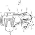
- Figs. 1 to 4 depict a taping head 10 for taping a wire harness W ( Fig. 3 ) wherein the taping head 10 comprises a base plate 12 with a mouth 14 for receiving the wire harness W.
- the mouth 14 has the shape of a broad slit which extends to an outer edge of the base plate 12 with a dead end of the slit having a semi-circular shape.
- a tape dispenser 16 is adapted to rotate a tape roll 17 around a centre C ( Fig. 3 ) of the mouth 14.
- the tape dispenser 16, which also comprises a mouth 15 having the shape of the mouth 14 of the base plate 12, is rotated around the centre C by means of a motor M ( Fig.
- the free end of the tape 17 is unwound from a tape roll which is rotatably supported on the tape dispenser 16 and the tape end is guided by means of a guide roll 34 which is loosely supported on a roll holder 35 mounted on the tape dispenser 16.
- a spring-loaded receptacle comprising two members 30, 32 is provided. Due to the two members 30, 32 the receptacle forms a gap 43 ( Fig. 3 ) for feeding the tape therethrough.
- the members 30 and 32 of the receptacle can be linearly shifted along a respective rod 31 and 33.
- the rods 31 and 33 are arranged in parallel to each other and each member 30, 32 of the receptacle is spring-loaded by means of a spring S1 and S2.
- the members 30, 32 of the receptacle will be pushed against the force of the springs S1 and S2 until the wire harness is located at the centre C of the mouths 14 and 15.
- the members 30 and 32 of the receptacle each comprise an inner wall 36, 38 which is concavely curved such that the shape of the walls corresponds to the outer shape of the wire harness. Furthermore, in the region of the gap 43 both members 30 and 32 comprise a rounded edge for slidingly guiding the tape.
- the free end of the tape can be clamped between an anvil 20 and a clamping element 22 as shown in Figs. 2 and 3 .
- the anvil 20 is a block-like element rigidly mounted to the rotatable tape dispenser 16 and the clamping element 22 comprises a rotatable lever mounted to the base plate 12.
- the rotatable lever can be rotated about an axis A1 which extends in parallel to the extension of the base plate 12 and the clamping element 22 can be rotated about at least 180° from the position shown in Fig. 1 (open position) to the position shown in Figs. 2 , 3 and 4 (closed or clamping position).
- a gear rod 26 ( Fig. 1 ) is provided which can be linearly shifted by means of an actuator 27.
- the linear movement of the gear rod 26 is converted into a rotational movement by means of a gearwheel 28 provided on the clamping element 22 such that the clamping element 22 rotates about the axis A1 if the actuator 27 is actuated to shift the gear rod 26.
- the clamping element 22 comprises a substantially triangular cutting blade 24 and a slit 42 whereas the anvil 20 comprises a slot (not shown) for receiving the cutting blade 24 and a protrusion 40 for clamping the tape.
- the protrusion 40 is received in the slit 42 of the clamping element 22 when the clamping element 22 has received the closed position.
- the tape will be held and clamped between the protrusion 40 and the anvil 20.
- the tape is not cut by the protrusion 40.
- the cutting is achieved by the cutting blade 24 received in the slot of the anvil 20.
- a contact surface of the anvil 20 is located adjacent an inlet of the mouth 15 of the tape dispenser 16 such that the outermost end of the tape is fixed at a location remote from the mouth 15 to avoid interference with the wire harness W.
- Fig. 4 shows a perspective view of a further embodiment.
- This embodiment corresponds to the embodiment of Figs. 1 to 3 but comprises two optional support levers 44 and 46 which are rotatable about an axis A2 running in parallel to the axis of the tape roll of the tape 17. Both support levers 44 and 46 can be independently swiveled about the axis A2 by means of a respective actuator.
- Each support lever comprises a support roll 48 ( Fig. 4 ) which can be located at the bottom side of the wire harness W after the wire harness has been placed in the mouths 14 and 15. When the taping head is moved along the length of the wire harness, the wire harness may slide on the support rolls 48.
- the taping head 10 When a taping process is initiated, the taping head 10 is located above the wire harness W and moved towards the wire harness such that the wire harness gets in touch with the walls 36, 38 of the members 30, 32 of the receptacle. If the taping head 10 is moved further downwards the members 30 and 32 are pushed upwards against the forces of the springs S1 and S2 such that the tape gets in contact with the wire harness. After the wire harness W is fully received in the mouths 14 and 15, the actuator 27 is actuated to rotate the clamping element 22 from the closed position shown in Fig. 2 to the open position shown in Fig. 1 . Thereafter, the free end of the tape is released and the tape dispenser 16 can be rotated around the centre C whereby the wire harness W is wrapped with the tape. Simultaneously, the taping head 10 is moved along the length of the wire harness.
- the taping head 10 is moved away from the wire harness W and into a position such that the tape is guided over the support surface of the anvil 20. Thereafter, the clamping element 22 is rotated about the axis A1 by means of the actuator 27 and the tape is cut and simultaneously clamped between the clamping element 21 and the anvil 20.
- the positioning of the taping head 10 can be done by means of a robot in an effective manner. Further, it is possible to move the taping head 10 along the length of the wire harness during the taping process such that a length of the wire harness is wrapped with the tape.
- the taping head described above is very compact and of light weight.
- the taping head can be used with standard taping rolls and the taping process can be done automatically by means of a robot.
- the clamping and the cutting of the tape is done automatically.
Priority Applications (4)
| Application Number | Priority Date | Filing Date | Title |
|---|---|---|---|
| EP21205051.2A EP4174882A1 (de) | 2021-10-27 | 2021-10-27 | Bandierer |
| EP22203260.9A EP4174883A3 (de) | 2021-10-27 | 2022-10-24 | Zapfkopf |
| US17/973,709 US20230129360A1 (en) | 2021-10-27 | 2022-10-26 | Taping head |
| CN202211323216.2A CN116022465A (zh) | 2021-10-27 | 2022-10-27 | 绑扎头 |
Applications Claiming Priority (1)
| Application Number | Priority Date | Filing Date | Title |
|---|---|---|---|
| EP21205051.2A EP4174882A1 (de) | 2021-10-27 | 2021-10-27 | Bandierer |
Publications (1)
| Publication Number | Publication Date |
|---|---|
| EP4174882A1 true EP4174882A1 (de) | 2023-05-03 |
Family
ID=78621675
Family Applications (2)
| Application Number | Title | Priority Date | Filing Date |
|---|---|---|---|
| EP21205051.2A Pending EP4174882A1 (de) | 2021-10-27 | 2021-10-27 | Bandierer |
| EP22203260.9A Pending EP4174883A3 (de) | 2021-10-27 | 2022-10-24 | Zapfkopf |
Family Applications After (1)
| Application Number | Title | Priority Date | Filing Date |
|---|---|---|---|
| EP22203260.9A Pending EP4174883A3 (de) | 2021-10-27 | 2022-10-24 | Zapfkopf |
Country Status (3)
| Country | Link |
|---|---|
| US (1) | US20230129360A1 (de) |
| EP (2) | EP4174882A1 (de) |
| CN (1) | CN116022465A (de) |
Citations (6)
| Publication number | Priority date | Publication date | Assignee | Title |
|---|---|---|---|---|
| WO2003013958A1 (en) * | 2001-07-26 | 2003-02-20 | Spirula Aktiebolag | Taping machine for wire harness |
| KR100802502B1 (ko) * | 2007-02-09 | 2008-02-13 | 신재학 | 휴대용 전선 테이핑 장치 |
| US20110017392A1 (en) * | 2009-03-03 | 2011-01-27 | Dania Nevarez Erives | Mechatronic gun for taping a harness |
| DE202015001990U1 (de) * | 2015-03-17 | 2015-04-17 | Kabatec GmbH & Co. KG | Vorrichtung zum Umwickeln eines länglichen Bündelgutes mit einem Klebeband |
| DE202017102503U1 (de) * | 2017-04-27 | 2017-05-17 | Lisa Dräxlmaier GmbH | Vorrichtung zum Umwickeln eines Leitungssatzes mit einem Band |
| CN108455356A (zh) * | 2018-01-18 | 2018-08-28 | 伯朝平 | 便携式胶带自动缠绕器 |
-
2021
- 2021-10-27 EP EP21205051.2A patent/EP4174882A1/de active Pending
-
2022
- 2022-10-24 EP EP22203260.9A patent/EP4174883A3/de active Pending
- 2022-10-26 US US17/973,709 patent/US20230129360A1/en active Pending
- 2022-10-27 CN CN202211323216.2A patent/CN116022465A/zh active Pending
Patent Citations (6)
| Publication number | Priority date | Publication date | Assignee | Title |
|---|---|---|---|---|
| WO2003013958A1 (en) * | 2001-07-26 | 2003-02-20 | Spirula Aktiebolag | Taping machine for wire harness |
| KR100802502B1 (ko) * | 2007-02-09 | 2008-02-13 | 신재학 | 휴대용 전선 테이핑 장치 |
| US20110017392A1 (en) * | 2009-03-03 | 2011-01-27 | Dania Nevarez Erives | Mechatronic gun for taping a harness |
| DE202015001990U1 (de) * | 2015-03-17 | 2015-04-17 | Kabatec GmbH & Co. KG | Vorrichtung zum Umwickeln eines länglichen Bündelgutes mit einem Klebeband |
| DE202017102503U1 (de) * | 2017-04-27 | 2017-05-17 | Lisa Dräxlmaier GmbH | Vorrichtung zum Umwickeln eines Leitungssatzes mit einem Band |
| CN108455356A (zh) * | 2018-01-18 | 2018-08-28 | 伯朝平 | 便携式胶带自动缠绕器 |
Also Published As
| Publication number | Publication date |
|---|---|
| US20230129360A1 (en) | 2023-04-27 |
| EP4174883A2 (de) | 2023-05-03 |
| EP4174883A3 (de) | 2023-08-16 |
| CN116022465A (zh) | 2023-04-28 |
Similar Documents
| Publication | Publication Date | Title |
|---|---|---|
| US7325764B2 (en) | Method and apparatus for winding field coils for dynamo-electric machines | |
| US4375229A (en) | Method and apparatus of automatically positioning wire ends for multi-mode end processing | |
| CA2602915A1 (en) | Rectangular wire coiling machine | |
| US4980958A (en) | Electrical cable-making apparatus | |
| EP0050910B1 (de) | Einrichtung zur Bearbeitung von Drahtenden | |
| CN111822925B (zh) | 一种线束及其自动化生产方法 | |
| US6279215B1 (en) | Automatic wire cutting and terminating apparatus | |
| EP4174882A1 (de) | Bandierer | |
| CN111822924B (zh) | 一种线束自动生产设备 | |
| CN214524553U (zh) | 覆盖机 | |
| JPS59132756A (ja) | コイル巻成法とコイルワインダ | |
| US5954918A (en) | Tape wrapping machine | |
| JP3703503B2 (ja) | ケーブル処理機械のためのケーブルを束ねる装置 | |
| US20090039194A1 (en) | Coiler and method for manufacturing a coil | |
| CN111790858B (zh) | 一种用于线束的转料机构 | |
| FR2602160A1 (fr) | Procede et machine modulaire de cambrage de fils metalliques | |
| JPH07211427A (ja) | 電線加工機における電線矯正装置 | |
| JP7347906B2 (ja) | ワイヤハーネスの自動ラッピングのための装着ヘッド及び方法 | |
| JP7347905B2 (ja) | ワイヤハーネスの所定の装着位置にクリップを位置決めするためのクリップモジュール、及びそのようなクリップモジュールを備えた装着ヘッド | |
| CN112499371B (zh) | 一种全自动盘线机 | |
| EP4362049A1 (de) | Zapfkopf | |
| US7419116B2 (en) | Method and apparatus for winding field coils for dynamo-electric machines | |
| CN112660529A (zh) | 一种金属丝圈自动捆扎生产线 | |
| US4571803A (en) | Fabrication apparatus for cushioned line support | |
| JPH0927222A (ja) | 電線案内ユニットおよび電線調尺切断装置 |
Legal Events
| Date | Code | Title | Description |
|---|---|---|---|
| PUAI | Public reference made under article 153(3) epc to a published international application that has entered the european phase |
Free format text: ORIGINAL CODE: 0009012 |
|
| STAA | Information on the status of an ep patent application or granted ep patent |
Free format text: STATUS: THE APPLICATION HAS BEEN PUBLISHED |
|
| AK | Designated contracting states |
Kind code of ref document: A1 Designated state(s): AL AT BE BG CH CY CZ DE DK EE ES FI FR GB GR HR HU IE IS IT LI LT LU LV MC MK MT NL NO PL PT RO RS SE SI SK SM TR |
|
| STAA | Information on the status of an ep patent application or granted ep patent |
Free format text: STATUS: REQUEST FOR EXAMINATION WAS MADE |
|
| 17P | Request for examination filed |
Effective date: 20231030 |
|
| RAV | Requested validation state of the european patent: fee paid |
Extension state: TN Effective date: 20231030 Extension state: MA Effective date: 20231030 |
|
| RBV | Designated contracting states (corrected) |
Designated state(s): AL AT BE BG CH CY CZ DE DK EE ES FI FR GB GR HR HU IE IS IT LI LT LU LV MC MK MT NL NO PL PT RO RS SE SI SK SM TR |
|
| RAP1 | Party data changed (applicant data changed or rights of an application transferred) |
Owner name: APTIV TECHNOLOGIES AG |