EP4173760B1 - Stützvorrichtung zur montage/demontage des getriebes von fahrzeugen mit erhöhter betriebsflexibilität - Google Patents
Stützvorrichtung zur montage/demontage des getriebes von fahrzeugen mit erhöhter betriebsflexibilität Download PDFInfo
- Publication number
- EP4173760B1 EP4173760B1 EP22202284.0A EP22202284A EP4173760B1 EP 4173760 B1 EP4173760 B1 EP 4173760B1 EP 22202284 A EP22202284 A EP 22202284A EP 4173760 B1 EP4173760 B1 EP 4173760B1
- Authority
- EP
- European Patent Office
- Prior art keywords
- fixture
- gearbox
- crossmember
- supporting
- tilting
- Prior art date
- Legal status (The legal status is an assumption and is not a legal conclusion. Google has not performed a legal analysis and makes no representation as to the accuracy of the status listed.)
- Active
Links
Images


Classifications
-
- B—PERFORMING OPERATIONS; TRANSPORTING
- B25—HAND TOOLS; PORTABLE POWER-DRIVEN TOOLS; MANIPULATORS
- B25H—WORKSHOP EQUIPMENT, e.g. FOR MARKING-OUT WORK; STORAGE MEANS FOR WORKSHOPS
- B25H1/00—Work benches; Portable stands or supports for positioning portable tools or work to be operated on thereby
- B25H1/0007—Work benches; Portable stands or supports for positioning portable tools or work to be operated on thereby for engines, motor-vehicles or bicycles
Definitions
- the present invention relates to a supporting fixture for assembling/disassembling the gearbox of vehicles with increased operating flexibility.
- gearbox supports which are used to support the gearbox during the execution of operations that require it to be dismounted and removed from its seat under the vehicle, in order to then remount it once the required maintenance is complete.
- Such supporting fixtures are typically mounted on the shank of a hydraulic handler provided inside the inspection pit where the operator works, or underneath the vehicle lift on which the vehicle undergoing maintenance is loaded.
- adjustable fixtures In order to limit the number of fixtures to keep in the workshop, so as to reduce the investment required to purchase them and the space necessary to store them when not in use, adjustable fixtures have been developed for supporting the gearbox of vehicles. Examples of support devices are known from US1556882A , US2006/231696A1 , US4809963A , US2004/169167A1 , US3218056A , EP3081342A1 , EP2719505A1 or US4787600A .
- the preamble of claim 1 is known from WO2011/095283A1 .
- Italian Patent Application no. MN2002A00033 describes an adjustable fixture that comprises, substantially, a longitudinal bar that can be associated with the shank of the hydraulic handler, on which a pair of crossmembers are slideably mounted which have respective pins for supporting the gearbox at a settable height, which are adapted to contact the housing of the gearbox from below, at its resting points.
- the pins of one of the crossmembers are arranged in a fixed position with respect to the longitudinal bar, while the pins of the other crossmember are mounted slideably thereupon.
- the longitudinal bar is associated so that it can oscillate with a mounting assembly on the shank of the hydraulic handler, so as to be able to modify its arrangement within a certain angle, together with that of the crossmembers and of the respective supporting pins.
- such fixture features a safety band connected to the longitudinal bar, which is adapted to be secured around the gearbox in order to prevent accidental shifts thereof.
- the aim of the present invention is to eliminate the above mentioned drawbacks in the prior art by providing a supporting fixture for assembling/disassembling the gearbox of vehicles with increased operating flexibility that is versatile in use and more or less universal irrespective of the model of vehicle undergoing maintenance.
- an object of the present invention is to provide a supporting fixture for assembling/disassembling the gearbox of vehicles that can be easily and rapidly used, thus simplifying the activities required to adapt the configuration of use of the fixture itself depending on the type of gearbox being worked on.
- Another object of the present invention is to provide a stable and reliable support of the gearbox, so as to prevent unwanted shifts in position thereof or even falls, with consequent risk of damage as well as of injury to the operators.
- another object of the present invention is to provide a supporting fixture for assembling/disassembling the gearbox of vehicles that has a simple structure and that is easy and practical to implement, safe in use and effective in operation, and of low cost.
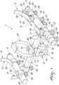
- the reference numeral 1 generally designates a supporting fixture for assembling/disassembling the gearbox of vehicles with increased operating flexibility.
- the fixture 1 comprises a load-bearing element 2 which extends along a longitudinal axis A and a pair of crossmembers 3 and 4 which are associated with the load-bearing element, each one of which is associated with respective supporting means 5 and 6 for supporting from below the gearbox of a vehicle undergoing maintenance (not shown).
- Each crossmember 3 and 4 is arranged substantially perpendicular to the load-bearing element 2.
- the load-bearing element 2 is arranged below the crossmembers 3 and 4 at their midpoint.
- the fixture 1 is intended to be coupled to the movable shank of a conventional lifting device positioned inside an inspection pit or under a vehicle lift, so that it can be placed below the gearbox of the vehicle undergoing maintenance that needs to be dismounted from its seat and then remounted once work is complete.
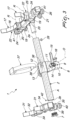
- the load-bearing element 2 is constituted by a tubular bar that is substantially quadrangular in cross-section, with a first end 2a open and a second end 2b closed by a plug 7.
- the load-bearing element 2 is associated with connecting means 8 which are intended to be mounted on the movable shank of the lifting device and which are associated with that load-bearing element by virtue of means for hinged coupling 9 about an oscillation axis O that is substantially perpendicular to the longitudinal axis A and substantially horizontal in use.
- the connecting means 8 comprise a beaker-like element 10 which is open downward and protrudes below the load-bearing element 2 which will be fitted over the tip of the movable shank of the handler, on which there is a bracket 11 which carries a first collar 12 through which the load-bearing element 2 is inserted so that it can slide along the longitudinal axis A.
- a first locking screw 13 to lock the relative sliding between the load-bearing element 2 and the first collar 12.
- the first locking screw 13 has a shank that passes through the first collar 12 and bites into the load-bearing element 2, and a tightening head that can be turned by the operator.
- the fixture 1 can be fitted with one or more reduction bushings, which are adapted to be accommodated inside the beaker-like element 10 in order to permit coupling with lifting devices with different diameters of the movable shank.
- the fixture 1 can also be coupled, again by way of the beaker-like element 10, to lifting platforms for mechanical elements such as movable vehicle lifts.
- the means for hinged coupling 9 comprise a pivot 14 that lies along the oscillation axis O for articulating the bracket 11 with respect to the beaker-like element 10, and a handle 15 for locking the relative rotation.
- the handle for locking 15 has a shank that passes through a curved slot defined on the bracket 11 and bites into the beaker-like element 10, and a clamping lever on the bracket itself.
- the crossmembers 3 and 4 are also constituted by respective tubular bars that are substantially quadrangular in cross-section, and are closed at the mutually opposite ends by corresponding plugs.
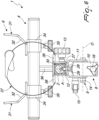
- the supporting means 5 of at least one of the crossmembers 3 are provided with at least one tilting support 17 which is associated with that crossmember so that it can rotate about a respective angular position adjustment axis R.
- the at least one tilting support 17 is adapted to assume different angular positions around the corresponding adjustment axis R as a function of the type of gearbox to be supported.
- the at least one tilting support 17 spontaneously adapts its angular position about the adjustment axis R under the action of the weight of the gearbox to be supported, without needing to perform preliminary adjustments of the configuration of the fixture 1.
- the at least one tilting support 17 is shaped so as to define a substantially concave contact surface 18 with the gearbox of the vehicle undergoing maintenance.
- the concave shape of such contact surface 18 makes it possible to ensure a hold and a stable support of the gearbox undergoing maintenance.
- the at least one tilting support 17 can have its contact surface 18 covered with a heat-shrunk protective sheath, for example made of crosslinked polyolefin.
- the adjustment axis R of the at least one tilting support 17 is substantially parallel to the longitudinal axis A.
- the at least one tilting support 17 is slideably associated along the corresponding crossmember 3 in order to be able to adapt its position as a function of the shape structure of the gearbox undergoing maintenance.
- a second collar 19 which is slideably coupled along the crossmember 3, to which the at least one tilting support 17 is pivoted about the corresponding adjustment axis R, and there is a second screw 21 for locking the sliding thereof.
- the at least one tilting support 17 is constituted by a substantially C-shaped element of substantially uniform thickness.
- the intrados of such tilting support 17 defines the contact surface 18.
- the at least one tilting support 17 is adapted to support gearboxes that have different geometries and dimensions of their outer housings.
- adjustable stroke-limiting means 22 which are adapted to limit the rotation angle of the at least one tilting support 17 about the corresponding adjustment axis R in at least one direction of rotation, and are associated with the crossmember 3.
- Such adjustable stroke-limiting means 22 comprise a threaded shank 23 that protrudes from a third collar 24 which can move along the crossmember 3, a movable head 25, on which to rest the tilting support 17, coupled along the shank itself and a third screw 26 for locking the sliding of the third collar 24 along the crossmember 3.
- the adjustable stroke-limiting means 22 can be positioned along the crossmember 3 as a function of the longitudinal position of the tilting support 17.
- the adjustable stroke-limiting means 22 are arranged along the crossmember 3 externally to the tilting support 17 in order to prevent accidental rotations thereof that could cause unexpected shifts in position or even falls of the gearbox resting upon it.
- adjustable stroke-limiting means 22 make it possible to block the tilting of the tilting support 17 once the gearbox undergoing maintenance is resting upon it, so as to prevent accidental shifts in position thereof or falls.
- the supporting means 5 of the crossmember 3 have two tilting supports 17 which tilt about respective adjustment axes R of the type described above.
- the two tilting supports 17 are arranged with the respective contact surfaces 18 facing so as to define a cradle for the containment of the gearbox of the vehicle undergoing maintenance.
- adjustment axes R of the two tilting supports 17 are arranged substantially parallel to the longitudinal axis A.
- the tilting supports 17 perform a counter-rotation about the respective adjustment axes R, thus clamping the gearbox in order to ensure a stable hold thereof.
- each one of the tilting supports 17 has respective adjustable stroke-limiting means 22 arranged externally along the crossmember 3, so as to prevent the accidental release of the gearbox of the vehicle undergoing maintenance.
- the crossmember 3 is associated with the load-bearing element 2 so as to be able to oscillate about the longitudinal axis A.
- the crossmember 3 is associated with a pivot 27 which is inserted so that it can rotate into the open end 2a of the load-bearing element 2.
- the crossmember 3 spontaneously adapts its angular position about the longitudinal axis A under the action of the weight of the gearbox to be supported, without needing to perform preliminary adjustments of the configuration of the fixture 1.
- an element 28 for locking the rotation of the crossmember 3 with respect to the structural element 2 is provided, which passes through an elongated slot 29 that extends on a plane that is perpendicular to the longitudinal axis A and is defined underneath the structural element 2 and is engaged in a dead hole 30 provided on the pivot 27.
- the supporting means 6 of the other crossmember 4 could also have one or, more preferably, two tilting supports 17 as described above, with optional adjustable stroke-limiting means 22.
- the crossmember 4 could also be associated with the load-bearing element 2 so that it can rotate about the longitudinal axis A.
- the supporting means 6 of the other crossmember 4 comprise at least two supporting elements 31 with fixed orientation, which are associated so that they can slide along that crossmember and are shaped so as to define respective substantially concave and mutually facing contact surfaces 32 with the gearbox of the vehicle undergoing maintenance.
- the supporting elements 31 can also have their contact surfaces 32 covered with a heat-shrunk protective sheath, for example made of crosslinked polyolefin.
- Each supporting element 31 is connected to a corresponding fourth collar 34, which is associated so that it can slide along the crossmember 4 and is coupled to a fourth screw 35 for locking the relative sliding.
- the crossmember 4 is mounted so that it can slide along the load-bearing element 2.
- a fifth collar 39 which can slide along the load-bearing element 2 and is connected to the crossmember 4, and a fifth screw 40 for locking the relative sliding.
- a spacer 36 can be advantageously provided between the fifth collar 39 and the crossmember 4 so as to position the latter at a different working height with respect to the crossmember 3.
- the spacer 36 makes it possible to adapt the geometry of the fixture 1 to that of the gearbox being worked on, which typically is larger at the point of attachment to the engine and is narrower at the other end, where it is attached to the transmission shaft.
- the fixture 1 can comprise a flexible safety element 37, such as a band, a strap or the like, which is adapted to be secured around the gearbox of the vehicle undergoing maintenance.
- a flexible safety element 37 such as a band, a strap or the like, which is adapted to be secured around the gearbox of the vehicle undergoing maintenance.
- Such flexible element 37 is associated with the load-bearing element 2 and passes through a pair of loops 38 which are integral with the first collar 12.
- crossmembers 3 and 4 are arranged substantially perpendicular to the load-bearing element 2 and above it. Furthermore, the associated supporting elements 17 and 31 protrude above the crossmembers 3 and 4 to receive the gearbox of the vehicle undergoing maintenance.
- the crossmember 4 generally has a shorter extension than the crossmember 3.
- the operation of the present invention is the following.
- the supporting elements 17 and 31 are positioned along the respective crossmembers 3 and 4 as a function of the type of gearbox being worked on, and the fixture 1 is positioned underneath and in contact with the gearbox so that it can support it.
- the gearbox is repositioned under the vehicle to be remounted in its seat.
- the shank of the lifting device is retracted so as to lower the fixture 1, after having disengaged the flexible element 37 from the gearbox.
- the movable heads 25 can be lowered in order to allow the tilting supports 17 to be opened and facilitate the disconnection of the fixture 1 from the gearbox being worked on.
- the fixture according to the invention is practical and rapid in use and makes it possible to work in complete safety.
Landscapes
- Engineering & Computer Science (AREA)
- Mechanical Engineering (AREA)
- Vehicle Cleaning, Maintenance, Repair, Refitting, And Outriggers (AREA)
- Automobile Manufacture Line, Endless Track Vehicle, Trailer (AREA)
- Gear-Shifting Mechanisms (AREA)
- General Details Of Gearings (AREA)
Claims (11)
- Eine Stützvorrichtung (1) zur Montage/Demontage des Getriebes von Fahrzeugen mit erhöhter Betriebsflexibilität, die ein Last tragendes Element (2) umfasst, welches sich entlang einer Längsachse (A) erstreckt, und ein Paar von Querträgern (3, 4), die mit dem Last tragenden Element (2) verbunden sind und von denen jeder mit entsprechenden Lagerungsmitteln (5, 6) zur Lagerung des Getriebes eines Fahrzeugs, das gewartet wird, von unten verbunden ist; wobei die Lagerungsmittel (5) mindestens eines der Querträger (3) mindestens eine Kipphalterung (17) umfassen, die mit dem Querträger so verbunden ist, dass er sich um eine entsprechende Winkelpositions-Einstellachse (R) drehen kann, ausgebildet, um so verschiedene Winkelpositionen um die entsprechende Einstellachse (R) in Abhängigkeit von der Art des zu lagernden Getriebes einzunehmen; dadurch gekennzeichnet, dass der mindestens eine Querträger (3) so mit dem Last tragenden Element (2) verbunden ist, dass er um die Längsachse (A) oszillieren kann.
- Die Vorrichtung (1) gemäß Anspruch 1, dadurch gekennzeichnet, dass die mindestens eine Kipphalterung (17) geformt ist, um eine im Wesentlichen konkave Kontaktfläche (18) mit dem Getriebe des zu wartenden Fahrzeugs zu bestimmen.
- Die Vorrichtung (1) gemäß Anspruch 1 und 2, dadurch gekennzeichnet, dass die Einstellachse (R) der mindestens einen Kipphalterung im Wesentlichen parallel zu der Längsachse (A) ist.
- Die Vorrichtung (1) gemäß mindestens einem der Ansprüche 1-3, dadurch gekennzeichnet, dass die mindestens eine Kipphalterung (17) entlang dem Querträger (3) verschiebbar angeschlossen ist.
- Die Vorrichtung (1) gemäß mindestens einem der Ansprüche 1-4, dadurch gekennzeichnet, dass sie verstellbare Hubbegrenzungsmittel (22) umfasst, die ausgebildet sind, um den Rotationswinkel der mindestens einen Kipphalterung (17) um die entsprechende Einstellachse (R) in mindestens einer Richtung zu begrenzen, und mit dem mindestens einen Querträger (3) verbunden sind.
- Die Vorrichtung (1) gemäß mindestens einem der Ansprüche 1-5, dadurch gekennzeichnet, dass die Lagerungsmittel (5) des Querträgers (3) zwei der Kipphalterungen (17) umfassen, die um jeweilige Einstellachsen (R) herum kippen.
- Die Vorrichtung (1) gemäß Anspruch 6, dadurch gekennzeichnet, dass die zwei Kipphalterungen (17) des mindestens einen Querträgers (3) so angeordnet sind, dass die jeweiligen Kontaktflächen (18) einander zugewandt sind, um einen Schlitten zur Aufnahme des Getriebes des zu wartenden Fahrzeugs zu bestimmen.
- Die Vorrichtung (1) gemäß Anspruch 6, dadurch gekennzeichnet, dass die Einstellachsen (R) der zwei Kipphalterungen (17) im Wesentlichen parallel zu der Längsachse (A) angeordnet sind.
- Die Vorrichtung (1) gemäß Anspruch 1, dadurch gekennzeichnet, dass die Lagerungsmittel (6) des anderen der Querträger (4) mindestens zwei Halterungselemente (31) umfassen, die verschiebbar entlang dem Querträger angebracht und geformt sind, um entsprechende im Wesentlichen konkave und einander zugewandte Kontaktflächen (32) mit dem Getriebe des zu wartenden Fahrzeugs zu bestimmen.
- Die Vorrichtung (1) gemäß Anspruch 1, dadurch gekennzeichnet, dass sie ein biegsames Sicherheitselement (37) umfasst, das ausgebildet ist, um um das Getriebe des zu wartenden Fahrzeugs herum gesichert zu werden, und mit dem Last tragenden Element (2) verbunden ist.
- Die Vorrichtung gemäß Anspruch 1, dadurch gekennzeichnet, dass sie Verbindungsmittel (8) umfasst, die mit dem beweglichen Schaft einer Hubvorrichtung verbunden werden können und mit dem Last tragenden Element (2) über Mittel zur schwenkbaren Kopplung (9) um eine Oszillationsachse (O) verbunden sind, die im Wesentlichen senkrecht zu der Längsachse (A) ist.
Applications Claiming Priority (1)
| Application Number | Priority Date | Filing Date | Title |
|---|---|---|---|
| IT102021000026750A IT202100026750A1 (it) | 2021-10-19 | 2021-10-19 | Attrezzatura di supporto per montare/smontare il cambio di veicoli ad incrementata flessibilità di impiego |
Publications (3)
| Publication Number | Publication Date |
|---|---|
| EP4173760A1 EP4173760A1 (de) | 2023-05-03 |
| EP4173760B1 true EP4173760B1 (de) | 2025-04-30 |
| EP4173760C0 EP4173760C0 (de) | 2025-04-30 |
Family
ID=79164960
Family Applications (1)
| Application Number | Title | Priority Date | Filing Date |
|---|---|---|---|
| EP22202284.0A Active EP4173760B1 (de) | 2021-10-19 | 2022-10-18 | Stützvorrichtung zur montage/demontage des getriebes von fahrzeugen mit erhöhter betriebsflexibilität |
Country Status (4)
| Country | Link |
|---|---|
| EP (1) | EP4173760B1 (de) |
| ES (1) | ES3034457T3 (de) |
| IT (1) | IT202100026750A1 (de) |
| PL (1) | PL4173760T3 (de) |
Family Cites Families (10)
| Publication number | Priority date | Publication date | Assignee | Title |
|---|---|---|---|---|
| US1556882A (en) * | 1925-05-16 | 1925-10-13 | Weaver Mfg Co | Axle stand |
| US3218056A (en) * | 1963-10-04 | 1965-11-16 | Owatonna Tool Co | Engine positioning stand |
| US4809963A (en) * | 1987-06-23 | 1989-03-07 | Kelly Thomas J | Adjustable engine stand |
| US4787600A (en) * | 1987-08-12 | 1988-11-29 | American Industrials Group | Transmission jack attachment |
| ITMN20020033A1 (it) | 2002-09-26 | 2004-03-27 | Alberto Frignani | Dispositivo di supporto per stacco e riattacco cambi di veicoli |
| CA2418797A1 (en) * | 2003-02-13 | 2004-08-13 | Hal Joseph Reinelt | Mobile engine lift apparatus |
| US7296787B2 (en) * | 2005-03-29 | 2007-11-20 | Spx Corporation | Retractable support apparatus and method |
| DE102010001519A1 (de) * | 2010-02-02 | 2011-09-22 | Maha Maschinenbau Haldenwang Gmbh & Co. Kg | Aufnahmevorrichtung für Kraftfahrzeugbaugruppen |
| ITPD20120294A1 (it) * | 2012-10-10 | 2014-04-11 | Carraro Drive Tech S P A | Banco specializzato per la manutenzione di assali e/o trasmissioni e/o differenziali |
| ITMO20150081A1 (it) * | 2015-04-16 | 2016-10-16 | Govoni S R L | Attrezzo per il sostegno del motore di un veicolo a flessibilita' incrementata. |
-
2021
- 2021-10-19 IT IT102021000026750A patent/IT202100026750A1/it unknown
-
2022
- 2022-10-18 ES ES22202284T patent/ES3034457T3/es active Active
- 2022-10-18 PL PL22202284.0T patent/PL4173760T3/pl unknown
- 2022-10-18 EP EP22202284.0A patent/EP4173760B1/de active Active
Also Published As
| Publication number | Publication date |
|---|---|
| ES3034457T3 (en) | 2025-08-18 |
| PL4173760T3 (pl) | 2025-09-01 |
| EP4173760A1 (de) | 2023-05-03 |
| EP4173760C0 (de) | 2025-04-30 |
| IT202100026750A1 (it) | 2023-04-19 |
Similar Documents
| Publication | Publication Date | Title |
|---|---|---|
| US9663304B2 (en) | Rotary chuck | |
| US9821987B2 (en) | Adjustable universal adaptor for a lifting jack | |
| US20160122168A1 (en) | Lifting apparatus for lifting and lowering vehicles, loads or the like | |
| CA2998723C (en) | Improved jack device and system | |
| US5680686A (en) | Strut spring compressor having floating compression head | |
| EP3254802A1 (de) | Halteeinrichtung zum einbau/ausbau einer in einen zugehörigen sitz gezwängte komponente | |
| WO2008137039A2 (en) | Vehicle jack assembly | |
| US5253407A (en) | Control rod drive endcap tool | |
| CN208840846U (zh) | 一种螺栓拆装工具 | |
| EP4173760B1 (de) | Stützvorrichtung zur montage/demontage des getriebes von fahrzeugen mit erhöhter betriebsflexibilität | |
| US3155373A (en) | Truck camper body jack | |
| EP3860802A1 (de) | Handhabungsvorrichtung zur wartung eines kolbens mit einem an dem kolben über einen kolbenbolzen befestigten pleuelkopf | |
| US3948484A (en) | Transfer case assembly removal tool | |
| US9186762B2 (en) | Turbine extension nut support tool | |
| EP0052586A2 (de) | Vorrichtung zum Erleichtern des Aufsetzens und Abnehmens schwerer Kraftfahrzeugräder | |
| US4155542A (en) | Device for holding workpieces | |
| EP1214176B1 (de) | Vorrichtung zum zerlegen oder wiederzusammenbau von feder/stossdämpfer-einheiten für fahrzeugaufhängungen | |
| US3040908A (en) | Equipment handling device | |
| CN214518710U (zh) | 一种快速拧螺丝装置 | |
| EP3738715B1 (de) | Vorrichtung zur abstützung von federdämpferanordnungen für maschinen zur montage/demontage von fahrzeugaufhängungen | |
| US5358227A (en) | Marine engine repair stand | |
| CN115898041B (zh) | 一种小单元构件拼装胎架 | |
| AU701357B2 (en) | Engine removal and mounting apparatus | |
| CN219074242U (zh) | 一种钢筋笼主筋间距控制装置 | |
| CN114183659A (zh) | 一种调节支架 |
Legal Events
| Date | Code | Title | Description |
|---|---|---|---|
| PUAI | Public reference made under article 153(3) epc to a published international application that has entered the european phase |
Free format text: ORIGINAL CODE: 0009012 |
|
| STAA | Information on the status of an ep patent application or granted ep patent |
Free format text: STATUS: THE APPLICATION HAS BEEN PUBLISHED |
|
| AK | Designated contracting states |
Kind code of ref document: A1 Designated state(s): AL AT BE BG CH CY CZ DE DK EE ES FI FR GB GR HR HU IE IS IT LI LT LU LV MC ME MK MT NL NO PL PT RO RS SE SI SK SM TR |
|
| P01 | Opt-out of the competence of the unified patent court (upc) registered |
Effective date: 20230528 |
|
| STAA | Information on the status of an ep patent application or granted ep patent |
Free format text: STATUS: REQUEST FOR EXAMINATION WAS MADE |
|
| 17P | Request for examination filed |
Effective date: 20231026 |
|
| RBV | Designated contracting states (corrected) |
Designated state(s): AL AT BE BG CH CY CZ DE DK EE ES FI FR GB GR HR HU IE IS IT LI LT LU LV MC ME MK MT NL NO PL PT RO RS SE SI SK SM TR |
|
| RIC1 | Information provided on ipc code assigned before grant |
Ipc: B25H 1/00 20060101AFI20241017BHEP |
|
| GRAP | Despatch of communication of intention to grant a patent |
Free format text: ORIGINAL CODE: EPIDOSNIGR1 |
|
| STAA | Information on the status of an ep patent application or granted ep patent |
Free format text: STATUS: GRANT OF PATENT IS INTENDED |
|
| INTG | Intention to grant announced |
Effective date: 20241128 |
|
| GRAS | Grant fee paid |
Free format text: ORIGINAL CODE: EPIDOSNIGR3 |
|
| GRAA | (expected) grant |
Free format text: ORIGINAL CODE: 0009210 |
|
| STAA | Information on the status of an ep patent application or granted ep patent |
Free format text: STATUS: THE PATENT HAS BEEN GRANTED |
|
| AK | Designated contracting states |
Kind code of ref document: B1 Designated state(s): AL AT BE BG CH CY CZ DE DK EE ES FI FR GB GR HR HU IE IS IT LI LT LU LV MC ME MK MT NL NO PL PT RO RS SE SI SK SM TR |
|
| REG | Reference to a national code |
Ref country code: CH Ref legal event code: EP Ref country code: GB Ref legal event code: FG4D |
|
| REG | Reference to a national code |
Ref country code: DE Ref legal event code: R096 Ref document number: 602022013843 Country of ref document: DE |
|
| REG | Reference to a national code |
Ref country code: IE Ref legal event code: FG4D |
|
| U01 | Request for unitary effect filed |
Effective date: 20250527 |
|
| P04 | Withdrawal of opt-out of the competence of the unified patent court (upc) registered |
Free format text: CASE NUMBER: APP_25913/2025 Effective date: 20250531 |
|
| U07 | Unitary effect registered |
Designated state(s): AT BE BG DE DK EE FI FR IT LT LU LV MT NL PT RO SE SI Effective date: 20250604 |
|
| REG | Reference to a national code |
Ref country code: ES Ref legal event code: FG2A Ref document number: 3034457 Country of ref document: ES Kind code of ref document: T3 Effective date: 20250818 |
|
| PG25 | Lapsed in a contracting state [announced via postgrant information from national office to epo] |
Ref country code: NO Free format text: LAPSE BECAUSE OF FAILURE TO SUBMIT A TRANSLATION OF THE DESCRIPTION OR TO PAY THE FEE WITHIN THE PRESCRIBED TIME-LIMIT Effective date: 20250730 Ref country code: GR Free format text: LAPSE BECAUSE OF FAILURE TO SUBMIT A TRANSLATION OF THE DESCRIPTION OR TO PAY THE FEE WITHIN THE PRESCRIBED TIME-LIMIT Effective date: 20250731 |
|
| PG25 | Lapsed in a contracting state [announced via postgrant information from national office to epo] |
Ref country code: HR Free format text: LAPSE BECAUSE OF FAILURE TO SUBMIT A TRANSLATION OF THE DESCRIPTION OR TO PAY THE FEE WITHIN THE PRESCRIBED TIME-LIMIT Effective date: 20250430 |
|
| PG25 | Lapsed in a contracting state [announced via postgrant information from national office to epo] |
Ref country code: RS Free format text: LAPSE BECAUSE OF FAILURE TO SUBMIT A TRANSLATION OF THE DESCRIPTION OR TO PAY THE FEE WITHIN THE PRESCRIBED TIME-LIMIT Effective date: 20250731 |
|
| PG25 | Lapsed in a contracting state [announced via postgrant information from national office to epo] |
Ref country code: IS Free format text: LAPSE BECAUSE OF FAILURE TO SUBMIT A TRANSLATION OF THE DESCRIPTION OR TO PAY THE FEE WITHIN THE PRESCRIBED TIME-LIMIT Effective date: 20250830 |
|
| U20 | Renewal fee for the european patent with unitary effect paid |
Year of fee payment: 4 Effective date: 20251020 |
|
| PG25 | Lapsed in a contracting state [announced via postgrant information from national office to epo] |
Ref country code: SM Free format text: LAPSE BECAUSE OF FAILURE TO SUBMIT A TRANSLATION OF THE DESCRIPTION OR TO PAY THE FEE WITHIN THE PRESCRIBED TIME-LIMIT Effective date: 20250430 |
|
| PG25 | Lapsed in a contracting state [announced via postgrant information from national office to epo] |
Ref country code: CZ Free format text: LAPSE BECAUSE OF FAILURE TO SUBMIT A TRANSLATION OF THE DESCRIPTION OR TO PAY THE FEE WITHIN THE PRESCRIBED TIME-LIMIT Effective date: 20250430 |
|
| PGFP | Annual fee paid to national office [announced via postgrant information from national office to epo] |
Ref country code: PL Payment date: 20251009 Year of fee payment: 4 |
|
| PG25 | Lapsed in a contracting state [announced via postgrant information from national office to epo] |
Ref country code: SK Free format text: LAPSE BECAUSE OF FAILURE TO SUBMIT A TRANSLATION OF THE DESCRIPTION OR TO PAY THE FEE WITHIN THE PRESCRIBED TIME-LIMIT Effective date: 20250430 |
|
| PGFP | Annual fee paid to national office [announced via postgrant information from national office to epo] |
Ref country code: ES Payment date: 20251103 Year of fee payment: 4 |
|
| PLBE | No opposition filed within time limit |
Free format text: ORIGINAL CODE: 0009261 |
|
| STAA | Information on the status of an ep patent application or granted ep patent |
Free format text: STATUS: NO OPPOSITION FILED WITHIN TIME LIMIT |
|
| REG | Reference to a national code |
Ref country code: CH Ref legal event code: L10 Free format text: ST27 STATUS EVENT CODE: U-0-0-L10-L00 (AS PROVIDED BY THE NATIONAL OFFICE) Effective date: 20260311 |
|
| 26N | No opposition filed |
Effective date: 20260202 |