EP4171971B1 - Reifen mit einer lauffläche, die für die griffigkeit auf nassboden im abgenutzen zustand optimiert ist - Google Patents
Reifen mit einer lauffläche, die für die griffigkeit auf nassboden im abgenutzen zustand optimiert ist Download PDFInfo
- Publication number
- EP4171971B1 EP4171971B1 EP21745362.0A EP21745362A EP4171971B1 EP 4171971 B1 EP4171971 B1 EP 4171971B1 EP 21745362 A EP21745362 A EP 21745362A EP 4171971 B1 EP4171971 B1 EP 4171971B1
- Authority
- EP
- European Patent Office
- Prior art keywords
- layer
- tread
- tgδ
- radially
- tyre
- Prior art date
- Legal status (The legal status is an assumption and is not a legal conclusion. Google has not performed a legal analysis and makes no representation as to the accuracy of the status listed.)
- Active
Links
Images
Classifications
-
- B—PERFORMING OPERATIONS; TRANSPORTING
- B60—VEHICLES IN GENERAL
- B60C—VEHICLE TYRES; TYRE INFLATION; TYRE CHANGING; CONNECTING VALVES TO INFLATABLE ELASTIC BODIES IN GENERAL; DEVICES OR ARRANGEMENTS RELATED TO TYRES
- B60C11/00—Tyre tread bands; Tread patterns; Anti-skid inserts
- B60C11/0041—Tyre tread bands; Tread patterns; Anti-skid inserts comprising different tread rubber layers
- B60C11/005—Tyre tread bands; Tread patterns; Anti-skid inserts comprising different tread rubber layers with cap and base layers
-
- B—PERFORMING OPERATIONS; TRANSPORTING
- B60—VEHICLES IN GENERAL
- B60C—VEHICLE TYRES; TYRE INFLATION; TYRE CHANGING; CONNECTING VALVES TO INFLATABLE ELASTIC BODIES IN GENERAL; DEVICES OR ARRANGEMENTS RELATED TO TYRES
- B60C11/00—Tyre tread bands; Tread patterns; Anti-skid inserts
- B60C11/0008—Tyre tread bands; Tread patterns; Anti-skid inserts characterised by the tread rubber
-
- B—PERFORMING OPERATIONS; TRANSPORTING
- B60—VEHICLES IN GENERAL
- B60C—VEHICLE TYRES; TYRE INFLATION; TYRE CHANGING; CONNECTING VALVES TO INFLATABLE ELASTIC BODIES IN GENERAL; DEVICES OR ARRANGEMENTS RELATED TO TYRES
- B60C1/00—Tyres characterised by the chemical composition or the physical arrangement or mixture of the composition
- B60C2001/0083—Compositions of the cap ply layers
-
- B—PERFORMING OPERATIONS; TRANSPORTING
- B60—VEHICLES IN GENERAL
- B60C—VEHICLE TYRES; TYRE INFLATION; TYRE CHANGING; CONNECTING VALVES TO INFLATABLE ELASTIC BODIES IN GENERAL; DEVICES OR ARRANGEMENTS RELATED TO TYRES
- B60C11/00—Tyre tread bands; Tread patterns; Anti-skid inserts
- B60C11/0008—Tyre tread bands; Tread patterns; Anti-skid inserts characterised by the tread rubber
- B60C2011/0016—Physical properties or dimensions
- B60C2011/0025—Modulus or tan delta
-
- B—PERFORMING OPERATIONS; TRANSPORTING
- B60—VEHICLES IN GENERAL
- B60C—VEHICLE TYRES; TYRE INFLATION; TYRE CHANGING; CONNECTING VALVES TO INFLATABLE ELASTIC BODIES IN GENERAL; DEVICES OR ARRANGEMENTS RELATED TO TYRES
- B60C11/00—Tyre tread bands; Tread patterns; Anti-skid inserts
- B60C11/0008—Tyre tread bands; Tread patterns; Anti-skid inserts characterised by the tread rubber
- B60C2011/0016—Physical properties or dimensions
- B60C2011/0033—Thickness of the tread
-
- Y—GENERAL TAGGING OF NEW TECHNOLOGICAL DEVELOPMENTS; GENERAL TAGGING OF CROSS-SECTIONAL TECHNOLOGIES SPANNING OVER SEVERAL SECTIONS OF THE IPC; TECHNICAL SUBJECTS COVERED BY FORMER USPC CROSS-REFERENCE ART COLLECTIONS [XRACs] AND DIGESTS
- Y02—TECHNOLOGIES OR APPLICATIONS FOR MITIGATION OR ADAPTATION AGAINST CLIMATE CHANGE
- Y02T—CLIMATE CHANGE MITIGATION TECHNOLOGIES RELATED TO TRANSPORTATION
- Y02T10/00—Road transport of goods or passengers
- Y02T10/80—Technologies aiming to reduce greenhouse gasses emissions common to all road transportation technologies
- Y02T10/86—Optimisation of rolling resistance, e.g. weight reduction
Definitions
- the present invention relates to a tire for a motor vehicle whose longitudinal grip performance on wet ground, in the worn state, is improved.
- the invention is more particularly suitable for a radial tire intended to equip a passenger vehicle or a van.
- a worn tyre is a tyre that has had a normal service life, reaching the legal limit of the wear indicators positioned on the sidewalls of the tyres.
- the legality in question here relates to the safety regulations for tires R30 and R54 of the UNECE (United Nations Economic Commission for Europe).
- This organization includes most European countries, in particular those of the European Union, but also countries outside Europe such as Japan, Thailand or Australia. These countries have validated an agreement for the mutual recognition of regulatory approvals of tires. In other words, a tire approved by regulation in one of the UNECE countries is also validated in all other countries of the organization where these regulations are in force.
- a passenger car or van tyre Before being marketed in UNECE countries, a passenger car or van tyre must comply with the regulatory requirements on safety according to regulations R30, R54 and the requirements on performance thresholds according to regulation R117.
- the wear indicators in the grooves or in the transverse notches of the tread, as well as their identification on the sidewalls of the tyres are requirements of these regulations.
- the regulation on performance thresholds R117 requires that tyres have a level of performance higher than the thresholds set by the regulation with regard to rolling resistance, grip on wet and snowy surfaces, and rolling noise.
- a passenger car tyre to be marketed in UNCE countries must have a rolling resistance value less than or equal to 6kg/t, as required by regulation R117.
- This same tyre must have wet braking at least 10% higher than the control tyre set by regulation R117. The methods and parameters of these tests are also defined by this regulation.
- the R117 performance threshold regulation applies to new tyres for their marketing on the UNECE market, but the question arises as to the effectiveness of these requirements depending on the wear of the tyres.
- the invention here relates to the durability of wet grip performance, i.e. the ability of the tire to still comply with regulatory thresholds even for a tire close to legal wear, according to an appropriate test method.
- a reference O, XX', YY', ZZ'
- the circumferential XX', axial YY', and radial ZZ' directions respectively designate a direction tangent to the rolling surface of the tire in the direction of rotation, a direction parallel to the axis of rotation of the tire, and a direction orthogonal to the axis of rotation of the tire.
- radially inner respectively radially outer, we mean closer, respectively further from the axis of rotation of the tire.
- axially inner is meant closer, respectively further from the equatorial plane of the tire, the equatorial plane of the tire being the plane passing through the middle of the tire tread and perpendicular to the axis of rotation of the tire.
- a tire comprises a crown, intended to come into contact with the ground via a tread, the two axial ends of which are connected via two sidewalls with two beads ensuring the mechanical connection between the tire and the rim on which it is intended to be mounted.
- the person skilled in the art defines the tread of a tire primarily using the following design features: the tread surface defining the overall width of the tread, and the sculpture characterized by a volumetric notch ratio.
- the “rolling surface” of the tread means the surface that groups together all the points of the tire that will come into contact with the ground under normal driving conditions. These points that will come into contact with the ground belong to the contact faces of the blocks.
- the "usual driving conditions” are the conditions of use defined by the ETRTO standard (European Tyre and Rim Technical Organization). These conditions of use specify the reference inflation pressure corresponding to the load capacity of the tire indicated by its load index and its speed code. These conditions of use can also be called “nominal conditions” or "conditions of use”.
- the total tread width is the axial distance between the axial ends of the tread surface, symmetrical with respect to the equatorial plane of the tire. In practical terms, an axial end of the tread surface does not necessarily correspond to a clearly defined point. Knowing that the tread is delimited externally, on the one hand, by the tread surface and, on the other hand, by two connecting surfaces with two sidewalls connecting said tread to two beads intended to ensure the connection with a mounting rim, an axial end can then be defined mathematically as the orthogonal projection, on the tread, of a theoretical point of intersection between the tangent to the tread surface, in the axial end zone of the tread surface, and the tangent to the connecting surface, in the radially outer end zone of the connecting surface.
- the total tread width corresponds substantially to the axial width of the contact surface when the tire is subjected to the recommended load and pressure conditions.
- elastomeric mixture an elastomeric material obtained by mixing its various constituents.
- An elastomeric mixture conventionally comprises an elastomeric matrix with at least one diene elastomer of natural or synthetic rubber type, at least one reinforcing filler of carbon black type and/or silica type, a crosslinking system most often based on sulfur, and protective agents.
- composition means a composition comprising the mixture and/or the reaction product of the different constituents used, some of these basic constituents being capable of, or intended to, react with each other, at least in part, during the different phases of manufacture of the composition, in particular during its crosslinking or vulcanization.
- part by weight per hundred parts by weight of elastomer (or pce), it is meant, for the purposes of the present invention, the part, by mass per hundred parts of elastomer present in the mixture composition considered.
- the choice of the material constituting the tread is an essential step in the design of a tire.
- it is an elastomeric mixture characterized by its dynamic properties, such as its viscoelastic loss Tg ⁇ (tangent delta) and/or its complex dynamic shear modulus G*.
- the viscoelastic loss, Tg ⁇ , and the complex shear modulus G* are generally determined when measuring the dynamic properties of the elastomeric mixture, on a viscoanalyzer (Metravib VA4000), according to the ASTM D 5992-96 standard.
- the measurement of the dynamic properties is carried out on a sample of vulcanized elastomeric mixture, i.e. cured to a conversion rate of at least 90%, the sample having the shape of a cylindrical test piece with a thickness equal to 2 mm and a section equal to 78.5 mm 2 .
- a temperature sweep is carried out at a constant temperature rise rate of +1.5°C/min.
- the results used are generally the complex dynamic shear modulus G*, comprising an elastic part G' and a viscous part G'', and the dynamic loss Tg ⁇ , equal to the ratio G''/G'.
- the glass transition temperature Tg is the temperature at which the dynamic loss Tg ⁇ reaches a maximum during the temperature scan.
- the value of G* measured at 23°C is representative of the rigidity of the rubber material, i.e. its resistance to elastic deformation.
- the tread of a tire is provided with a sculpture comprising in particular sculpture elements or elementary blocks delimited by various main grooves, longitudinal, transverse or oblique, the elementary blocks being able to comprise various incisions or finer sipes.
- the grooves constitute channels intended to evacuate water when driving on wet ground and define the edges of the sculpture elements.
- the volume of the tread decreases due to the loss of material due to friction with the road surface.
- the tread is at its maximum thickness.
- the height of the elementary blocks of the tread pattern decreases, and the stiffness of these blocks increases.
- the increase in the stiffness of the elementary blocks of the tread pattern results in a decrease in certain tire performances, such as wet grip, even when the height of the tread blocks is at the legal wear indicator.
- the patent EP2163403B1 offers a tread comprising two layers of materials superimposed radially, and placed externally on the crown of a tire. The interface between the two layers making up the tread is undulating. The tread pattern adapts according to the wear of the tire to reveal other cutouts.
- a pneumatic tire with a multi-layer tread and a manufacturing method thereof are disclosed.
- the tread comprises a first inner layer, radially inner to an outer layer intended to be in contact with a ground.
- the elastic modulus of extension-compression of the inner layer is greater than that of the outer layer, and on the other hand the radially inner layer of the tread has a profile with radially oriented protuberances outwardly spread over the entire width of the tread.
- a multi-layer tread of at least two superimposed layers is disclosed, such that their common interface is above the minimum profile depth, so that the lower part of these layers, in a later phase of the life of the tire comes into contact with the ground.
- the patent FR3059421 discloses a planing method for preparing tires for worn-state testing.
- the inventors set themselves the goal of creating a tire that maintains wet grip performance throughout its life without compromising other performance such as rolling resistance.
- the principle of the invention is to achieve a gain in wet grip in return for an increase in rolling resistance in controlled proportions, because the tire of the invention must comply with the regulations on performance thresholds including rolling resistance.
- the addition of the intermediate layer M2 optimized for grip in place of part of the volume of the most radially outer layer M3, optimized for rolling resistance creates a new balance of performance. After wear of the M3 layer of the tread, the tire still has a high wet grip potential with the intermediate layer M2. In fact, the tire of the invention, throughout its period of use, potentially maintains wet grip performance that complies with the regulations.
- the multilayer tread comprises an intermediate layer M2 arranged radially external to the first layer M1 in contact with it, and radially internally with the most radially external layer M3, extending axially at least in sections along the first layer M1.
- the intermediate layer M2 is optimized for wet grip with a relatively high viscoelastic dissipation compared to that of the mixture of the radially outermost layer M3.
- the viscoelastic loss of the mixture of the intermediate layer M2 is 0.25, then for the radially outermost layer M3, the viscoelastic loss will be of the order of 0.17.
- the intermediate layer M2 is flexible in the sense that its shear stiffness is relatively low compared to the stiffnesses of the adjacent materials. The high hysteresis combined with the low stiffness of the mixture of the intermediate layer M2 tend to improve wet grip.
- the shear modulus of the mixture of the first layer M1 could be of the order of 25 Mpa, and that of the mixture of the intermediate layer M2 of the order of 1.7 Mpa. With such values, the mixture of the layer M1 is said to be rigid compared to that of the intermediate layer M2.
- the phenomenon of tire adhesion on wet ground occurs in three stages.
- the first stage consists of drying the ground by evacuating water thanks to the tread pattern, then a phase of contact with the ground by adhesion and indentation. And it is precisely in the indentation phase that the asperities of the ground cling to the layer of mixture to oppose the movement.
- the first relation (a) means that the first layer M1 must be very rigid with respect to the intermediate layer M2.
- the layer M1 is never in contact with the ground, on the one hand it participates in the stiffening of the tread, useful for generating sufficient drift thrusts, and on the other hand due to its high rigidity, during manufacturing it is the support for laying the intermediate layer M2 which is relatively "soft".
- Laying the intermediate layer M2 under these conditions makes it possible to have its radially outer contour parallel to the axial profile of the mold.
- the axial profile of the mold is defined so as to obtain a uniform distribution of vertical pressures in the contact area. The uniformity of the contact pressures is necessary to obtain regular wear of the tread in the axial direction.
- the intermediate layer M2 after wear of the most radially outer layer M3 is intended to be in contact with the ground, and its radially outer profile parallel to the axial profile of the mold therefore guarantees the obtaining of regular wear. Furthermore, the penetrations between the layers are limited with the first layer M1 as a support for laying.
- the ratio G'_M1/G'_M2 is in the range [7; 25], which means that the shear stiffness of the first layer M1 is at least seven times higher than that of the intermediate layer M2 to begin to perceive the effects of the invention.
- G'_M1/G'_M2 greater than 25 the effect asymptotically decreases.
- the second relation (b) on the viscoelastic loss indicates the hysteresis gap necessary to perceive the gain in the adhesion potential of the mixture of the intermediate layer M2 which is intended to come into contact with the ground, with respect to the most radially outer layer M3.
- a relative gap of at least 20% between the viscoelastic losses of the elastomeric mixtures of the two layers is necessary to begin to perceive the effects of the invention.
- the ratio of the radial thickness of the radially outermost layer M3 divided by the radial thickness of the intermediate layer M2, Thickness_M3/ThicknessM2, is included in the interval [3; 10], said thicknesses being measured on the axis of symmetry of a meridian plane of the tire.
- the volume of a layer is directly proportional to its radial thickness in a meridian plane.
- the distribution of the volumes of the tread layers M1, M2, and M3 is the second lever to be combined with the mechanical and hysteretic properties of the layers to achieve the invention.
- the hysteresis-optimized tread layer M3 represents the largest volume. The invention works if the intermediate layer M2 has a volume greater than or equal to one tenth of the volume of the radially outermost layer M3, and less than or equal to one third of this volume.
- the volume of the intermediate layer M2 is less than one tenth of the volume of the layer M3, then the gain in wet grip is not significant in this case. Conversely, if the intermediate layer M2 is greater than one third of the volume of the radially outermost layer M3, then the degradation of rolling resistance becomes prohibitive.
- the ratio of the shear stiffness modulus of the elastomeric mixture of the first layer M1, divided by the shear stiffness modulus of the elastomeric mixture of the radially outermost layer M3, G'_M1/G'_M3 is within the range [7; 25].
- the layer M3 of the tread is intended to be in contact with the ground when the tire is new and has the largest volume among the three layers.
- the performance compromise advocates a radially outermost layer M3 with low hysteresis and a shear stiffness of the same order of magnitude as for the second intermediate layer M2.
- the ratio G'_M1/G'_M3 is included in the interval [6; 22], similarly the ratio G'_M1/G'_M2 is included in the interval [6; 22].
- the difference in mechanical properties between the layers M2 and M3 is mainly at the level of hysteresis, but in terms of rigidities, the shear moduli are of the same order of magnitude compared to the mixture of the first layer M1.
- the shear stiffness modulus of the elastomeric mixture of the sub-layer is less than or equal to 1.5 MPa.
- the multi-layer tread is connected to a so-called "soft" sub-layer, with respect to the shear stiffness of the elastomeric mixture of the first layer M1.
- the viscoelastic loss Tg ⁇ _M2 of the elastomeric mixture of the intermediate layer M2 is greater than or equal to 0.2, and even more advantageously, the viscoelastic loss Tg ⁇ _M2 of the elastomeric mixture of the intermediate layer M2, and the viscoelastic loss Tg ⁇ _M3 of the elastomeric mixture of the radially outermost layer M3, are connected by the relation: (Tg ⁇ _M2 - Tg ⁇ _M3)/Tg ⁇ _M2 ⁇ 30%.
- the relative difference of the viscoelastic losses of the elastomeric mixtures of the layers M2 and M3 are in a ratio greater than 30%.
- the shear stiffness modulus G'_M1 of the elastomeric mixture of the first layer M1 is greater than 7 MPa, and even more preferably, the shear stiffness modulus G'_M1 of the elastomeric mixture of the first layer M1 is greater than or equal to 12 MPa.
- the rigidities of the layers of the tread are correlated.
- the first layer M1 has the greatest rigidity, with a value of at least 7 Mpa, and preferably greater than or equal to 12 Mpa.
- the planed profile of the tread being by convention, defined such that the residual sculpture height after planing is 2 mm over the entire axial width of the tread, the maximum deviation Emax being the radial distance between the planed profile of the tread, and the radially outer profile of the first layer M1 characterized in that the maximum deviation Emax is constant at ⁇ 5 mm over at least a central portion of the tread.
- the grooves of the tread being the deepest grooves of the sculpture, the material appearing at the bottom of the groove is the same as the material constituting the most radially outer layer M3 of the tread.
- the tread comprising tread blocks separated by grooves oriented essentially circumferentially
- the first layer M1 is, axially facing certain tread blocks, extended radially outwards by at least one reinforcing element extending radially from the radially outer surface of the first layer M1 towards the outside of the tread up to a radial height greater than 75% of the radial thickness of the tread, said reinforcing element being of variable axial width, from a maximum value less than 50% of the axial width of said tread block, said axial width decreasing when moving radially upwards.
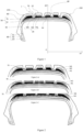
- the three layers of compounds M1, M2, and M3 of the tread 20 are radially superimposed on the sub-layer 30, and oriented radially outwards.
- the first layer of elastomeric compound M1 is shown in the figure 1 by a black background, and is placed most radially internally on the sub-layer 30.
- the second intermediate layer M2 is radially externally placed on the first layer M1.
- the intermediate layer M2 is represented by a wave-shaped pattern.
- the third, most radially outer layer M3 laid radially outwardly on the intermediate layer M2 is represented by a light-background pattern with black dots.
- This layer, the most radially outer M3, comprises the tread surface 10 and is intended to be in contact with a ground when the tire is new.
- the tread 20 also comprises grooves 80 oriented mainly circumferentially and determining successive tread blocks in the axial direction from the shoulder 15G to the shoulder 15D.
- Each groove 80 is delimited radially inwards by a groove bottom.
- the radially outermost layer M3 extends continuously over the entire axial width of the tread passing through the bottom of the grooves, while the layers M2 and M3 are discontinuous.
- there is an indicator 70 of the state of wear of the tread is an indicator 70 of the state of wear of the tread. This indicator extends radially outwards from the bottom of the groove over a height of 1.6 mm.
- FIG 2 represents successive states of wear of the tire, 2-A, 2-B and 2-C.
- the Figure 2-A shows the new tire with the tread made up of the three layers of elastomeric compound M1, M2, M3.
- the radially outermost layer M3 is completely worn, and the intermediate layer M2 comes directly into contact with the ground.
- the tire still has potential for use, the wear indicators 70 having a radial height lower than that of the intermediate layer M2.
- the tire is worn.
- the tread height is at the wear indicator level 70.
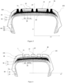
- FIG 3 represents the diagram of a tire of a second embodiment of the invention in a meridian plane where the first layer M1 of the tread extends radially outwardly in the form of a trapezium 27 on the tread surface 10 so as to axially border the grooves 80 on either side.
- each tread block delimited by the grooves 80 are bordered by the extensions of the first layer M1 in the form of a trapezium 27 on either side.
- the blocks located at the ends 15G and 15D are bordered only on the side oriented towards the center of the tread.
- FIG 4 shows the third embodiment of the invention, which is characterized by the use of three layers M1, M2 and M3 continuous over the entire width of the top.
- the tire may contain a hoop reinforcement comprising one or two hoop layers, radially externally superimposed on the crown reinforcement 50.
- Each hoop layer is formed of reinforcements parallel to each other, making angles at most equal to 2.5° with the circumferential direction.
- the invention has been more particularly studied for a passenger car tire of standardized designation, according to the ETRTO (European Technical Organization for Rims and Tires), 245/45 R18 100W.
- ETRTO European Technical Organization for Rims and Tires
- 245/45 R18 100W 245/45 R18 100W.
- a version conforming to the first embodiment of the invention has been produced, compared to a conventional state-of-the-art tire with a single-layer tread.
- the M1, M2, and M3 layers of the tread are characterized by their dynamic and geometric properties grouped in the following table: [Table 1] Radial thickness (mm) G' in Mpa Tg ⁇ Volume in cm3 Undercoat 1.6 0.2 0.06 785 Mix layer M1 1.3 25 0.27 342 Mix layer M2 1.3 1.7 0.25 330 M3 layer mix 4.5 1.4 0.17 1331
- the underlayer laid radially externally to the crown reinforcement has a radial thickness of 1.6 mm, measured on the axis of symmetry of a meridian plane of the tire. This thickness corresponds to a volume per wheel turn of 785 cm3.
- Undercoat Component Pce NR (a) 100 Carbon black 4 6-PPD (b) 2.2 DPG (c) 2.1 ZnO (d) 1.5 Stearic acid 3 Resin 29.3 HTO (e) 38 CBS (f) 1.4 Sulfur 1.6 With : a. NR: Natural Rubber b. 6-PPD: N-1,3-dimethylbutyl-N'-phenyl-p-phenylenediamine (“Santoflex 6-PPD" from Flexsys) - antioxidant c. DPG: Diphenylguanidine (“Perkacit” DPG from Flexsys company) - vulcanization activator d.
- ZnO Zinc Oxide, Vulcanization e.
- HTO Sunflower oil with 85% oleic acid by weight, “Lubrirob Tod 1880” from Novance - plasticizer f.
- CBS N-cyclohexyl-2-benzothiazyl-sulfenamide (Santocure CBS from Flexsys) - vulcanization accelerator
- the underlayer has a shear stiffness modulus of 0.45 Mpa, and a viscoelastic loss of 0.06.
- the underlayer is optimized in hysteresis to contribute to achieving the rolling resistance performance target.
- the first layer M1 of the tread laid radially externally on the sub-layer has a thickness of 1.3 mm, measured on the axis of symmetry of a meridian plane of the tire, which represents a volume of 342 cm3.
- composition for the first layer M1 is in the following table: [Table 3]
- M1 layer Component Pce NR (a) 100 Carbon black 70 Formophenolic resin 12 6-PPD (b) 2.5 Sulfur 3 ZnO (c) 3 Stearic acid 2 CBS (d) 2 HTMT (e) 4 Sulfur 3 With : a.
- NR Natural Rubber
- 6-PPD N-1,3-dimethylbutyl-N'-phenyl-p-phenylenediamine ("Santoflex 6-PPD" from Flexsys) - antioxidant
- ZnO Zinc Oxide, Vulcanization
- CBS N-cyclohexyl-2-benzothiazyl-sulfenamide (Santocure CBS from Flexsys) - vulcanization accelerator e.
- HTMT Resin
- the shear stiffness modulus of the elastomeric mixture of the first layer M1 is 25 Mpa, for a viscoelastic loss measured by a Tg ⁇ value of 0.27.
- the intermediate layer M2 of the tread laid radially outwardly to the first layer M1 has a radial thickness of 1.3 mm, measured on the axis of symmetry of a meridian plane.
- the volume of the intermediate layer M2 is 330 mm3.
- composition for this layer is: [Table 4] M2 layer Component pce SBR (a) 100 Silica (b) 110 Coupling agent (c) 9 Liquid plasticizer (d) 20 Resin plasticizer (e) 50 Black 5 Zinc oxide 3 Stearic acid 2 Antioxidant (f) 2 Accelerator (g) 2 DPG 2 Sulfur 1 With : (a) SBR with 27% styrene, butadiene -1,2:5%, cis-1,4:15%, trans -1,4: 80% Tg - 48°C (b) Silica “Zeosil1165MP” from Solvay with a BET surface area of 160m2 / g (c) Silane TESPT “SI69” from Evonik company (d) TDAE “Flexon 630” oil from Shell (e) “Escorez 2173” resin from Exxon (f) Antioxidant “Santoflex 6PPD” from the company Solutia (g) “S2 layer Com
- the shear stiffness modulus is 1.7 Mpa
- the viscoelastic loss is Tg ⁇ of 0.25.
- the shear modulus of the first layer M1 is about 15 times that of the intermediate layer M2, and the viscoelastic losses are of the same order of magnitude.
- the intermediate layer M2 is intended to come into contact with the ground, a relatively soft mixture, and a high hysteresis are expected for good wet grip performance.
- the radially outermost layer M3 of the tread of the tire of the invention is radially externally placed on the intermediate layer M2 has a radial thickness of 4.5 mm, measured on the axis of symmetry of a meridian plane. Its volume at the wheel turn of 131 cm3. Its shear rigidity modulus is 1.4 Mpa, and the viscoelastic loss Tg ⁇ _M3 is 17%.
- composition for this layer is: [Table 5] M3 layer Component Pce SBR (a) 100 Silica (b) 70 Coupling agent (c) 6 Liquid plasticizer (d) 30 Plasticizer resin (e) 0 Carbon black 5 With : (a) SBR with 27% styrene, butadiene -1,2:5%, cis-1,4:15%, trans -1,4: 80% Tg - 48°C (b) Silica “Zeosil1165MP” from Solvay with a BET surface area of 160m2 / g (c) Silane TESPT “SI69” from Evonik company (d) TDAE “Flexon 630” oil from Shell (e) “Escorez 2173” resin from Exxon
- the tread with the three layers M1, M2, and M3 was obtained by a volume coextrusion process which allows the three layers to be extruded simultaneously. Such a process is described in the patent WO2018087467A1 .
- the inventors observed a gain in wet grip at the end of the tire's life improved by 5% against a loss in resistance of 0.06 kg/t.
- the simulation of the wear of the control tires and of the invention was carried out by planing the tread of the test and control tires as described in the patent FR3059421A1 .
Landscapes
- Engineering & Computer Science (AREA)
- Mechanical Engineering (AREA)
- Tires In General (AREA)
Claims (11)
- Reifen (1), umfassend eine Gürtelverstärkung (50), eine Unterschicht (30) und einen mehrschichtigen Laufstreifen (20), der aus drei Schichten aus Elastomermischungen (M1, M2, M3) gebildet wird, von denen die radial äußerste Schicht (M3) dazu bestimmt ist, über eine Lauffläche (10) mit einem Boden in Kontakt zu gelangen:- wobei die Gürtelverstärkung (50) radial innerhalb des mehrschichtigen Laufstreifens (20) angeordnet ist;- wobei die Unterschicht (30) radial außerhalb der Gürtelverstärkung (50) und radial innerhalb des mehrschichtigen Laufstreifens (20) angeordnet ist und sich über die gesamte axiale Breite der Gürtelverstärkung (50) erstreckt;- wobei der mehrschichtige Laufstreifen (20) eine erste Schicht (M1) beinhaltet, die radial außerhalb der Unterschicht (30) angeordnet ist und sich zumindest abschnittsweise axial über die gesamte oder einen Teil der axialen Breite der Unterschicht (30) erstreckt;- wobei der Laufstreifen auch eine radial äußerste Schicht (M3) beinhaltet, die mit einer Lauffläche (10) versehen ist;- wobei der mehrschichtige Laufstreifen (20) eine Zwischenschicht (M2) umfasst, die radial außerhalb der ersten Schicht (M1) in Kontakt mit ihr und radial innerhalb der Schicht (M3) angeordnet ist und sich zumindest abschnittsweise entlang der Schicht (M1) erstreckt;- wobei die Elastomermischungen der ersten Schicht (M1), der Zwischenschicht (M2), der radial äußersten Schicht (M3), die dazu bestimmt ist, mit einem Boden in Kontakt zu gelangen, einen Scherfestigkeitsmodul G'_M1, G'_M2 bzw. G'_M3 aufweisen und einen viskoelastischen Verlust Tgδ_M1, Tgδ_M2 bzw. Tgδ_M3 aufweisen, die bei 23 °C bei 10 Hz und unter einer Scherwechselverformung von 10 % des Materials jeder Schicht gemessen werden,dadurch gekennzeichnet, dassdas Verhältnis G'_M1/G'_M2 in dem Intervall [7; 25] enthalten ist;der viskoelastische Verlust Tgδ_M2 der Elastomermischung der Zwischenschicht (M2) und der viskoelastische Verlust Tgδ_M3 der Elastomermischung der radial äußersten Schicht (M3) durch die folgende Gleichung verbunden sind: (Tgδ _M2-Tgδ_M3)/Tgδ_M2 ≥ 20 %;das Verhältnis der radialen Dicke der radial äußersten Schicht (M3), dividiert durch die radiale Dicke der Zwischenschicht (M2), Dicke_M3/Dicke_M2, in dem Intervall [3; 10] enthalten ist, wobei die Dicken auf der Symmetrieachse einer Meridianebene des Reifens gemessen werden.
- Reifen (1) nach Anspruch 1, dadurch gekennzeichnet, dass das Verhältnis des Scherfestigkeitsmoduls der Elastomermischung der ersten Schicht (M1), dividiert durch den Scherfestigkeitsmodul der Elastomermischung der radial äußersten Schicht (M3), G'_M1/G'_M3, in dem Intervall [7; 25] enthalten ist.
- Reifen (1) nach dem vorhergehenden Anspruch, wobei der Scherfestigkeitsmodul der Elastomermischung der Unterschicht (30) kleiner als oder gleich 1,5 MPa ist.
- Reifen (1) nach einem der vorhergehenden Ansprüche, dadurch gekennzeichnet, dass der viskoelastische Verlust Tgδ_M2 der Elastomermischung der Zwischenschicht (M2) größer als oder gleich 0,2 ist.
- Reifen (1) nach einem der vorhergehenden Ansprüche, dadurch gekennzeichnet, dass der viskoelastische Verlust Tgδ_M2 der Elastomermischung der Zwischenschicht (M2) und der viskoelastische Verlust Tgδ_M3 der Elastomermischung der radial äußersten Schicht M3 durch die folgende Gleichung verbunden sind: (Tgδ_M2 - Tgδ_M3)/Tgδ_M2 ≥ 30 %.
- Reifen (1) nach Anspruch 1, dadurch gekennzeichnet, dass der Scherfestigkeitsmodul G'_M1 der Elastomermischung der ersten Schicht (M1) größer als 7 MPa ist.
- Reifen (1) nach dem vorhergehenden Anspruch, dadurch gekennzeichnet, dass der Scherfestigkeitsmodul G'_M1 der Elastomermischung der ersten Schicht (M1) größer als oder gleich 12 MPa ist.
- Reifen (1) nach einem der vorhergehenden Ansprüche, wobei das abgehobelte Profil des Laufstreifens konventionshalber so definiert ist, dass die Restprofilhöhe nach dem Abhobeln über die gesamte axiale Breite des Laufstreifens 2 mm beträgt, wobei die maximale Abweichung Emax der radiale Abstand zwischen dem abgehobelten Profil des Laufstreifens und dem radial äußeren Profil der ersten Schicht (M1) ist, dadurch gekennzeichnet, dass die maximale Abweichung Emax über mindestens einen zentralen Abschnitt des Laufstreifens auf ± 5 mm konstant ist.
- Reifen (1) nach einem der vorhergehenden Ansprüche, wobei die Rillen (80) des Laufstreifens die tiefsten Nuten des Profilblocks sind, wobei das am Rillenboden erscheinende Material das gleiche Material ist wie das Material, aus dem die radial äußerste Schicht (M3) des Laufstreifens besteht.
- Reifen (1) nach einem der vorhergehenden Ansprüche, dadurch gekennzeichnet, dass die Zwischenschicht (M2), die radial außerhalb der ersten Schicht (M1) angeordnet ist und radial innerhalb mit der radial äußersten Schicht (M3) in Kontakt ist, sich axial durchgehend entlang der ersten Schicht (M1) erstreckt.
- Reifen (1) nach einem der vorhergehenden Ansprüche, wobei der Laufstreifen (10) Profilblöcke (25) umfasst, die durch im Wesentlichen umfänglich ausgerichtete Rillen (80) getrennt sind, dadurch gekennzeichnet, dass die erste Schicht (M1), axial gegenüber einigen Profilblöcken (25), radial nach außen durch mindestens ein verstärkendes Element (27) verlängert wird, das sich radial von der radial äußeren Fläche der ersten Schicht (M1) nach außerhalb des Laufstreifens (10) bis zu einer radialen Höhe von mehr als 75 % der radialen Dicke des Laufstreifens erstreckt, wobei das verstärkende Element (27) eine variable axiale Breite ausgehend von einem Höchstwert von weniger als 50 % der axialen Breite des Profilblocks (25) hat, wobei die axiale Breite radial nach oben hin abnimmt.
Applications Claiming Priority (2)
| Application Number | Priority Date | Filing Date | Title |
|---|---|---|---|
| FR2006739A FR3111845B1 (fr) | 2020-06-26 | 2020-06-26 | Pneumatique comportant une bande de roulement optimisée en adhérence sur sol mouillé à l’état usé |
| PCT/FR2021/051169 WO2021260335A1 (fr) | 2020-06-26 | 2021-06-24 | Pneumatique comportant une bande de roulement optimisée en adhérence sur sol mouillé a l'état usé |
Publications (2)
| Publication Number | Publication Date |
|---|---|
| EP4171971A1 EP4171971A1 (de) | 2023-05-03 |
| EP4171971B1 true EP4171971B1 (de) | 2025-02-19 |
Family
ID=72644434
Family Applications (1)
| Application Number | Title | Priority Date | Filing Date |
|---|---|---|---|
| EP21745362.0A Active EP4171971B1 (de) | 2020-06-26 | 2021-06-24 | Reifen mit einer lauffläche, die für die griffigkeit auf nassboden im abgenutzen zustand optimiert ist |
Country Status (5)
| Country | Link |
|---|---|
| US (1) | US12115817B2 (de) |
| EP (1) | EP4171971B1 (de) |
| JP (1) | JP2023533213A (de) |
| FR (1) | FR3111845B1 (de) |
| WO (1) | WO2021260335A1 (de) |
Families Citing this family (3)
| Publication number | Priority date | Publication date | Assignee | Title |
|---|---|---|---|---|
| FR3153025B1 (fr) * | 2023-09-14 | 2025-08-15 | Michelin & Cie | Pneumatique optimisé en comportement routier et en résistance au roulement |
| FR3153026B1 (fr) * | 2023-09-14 | 2025-09-19 | Michelin & Cie | Pneumatique optimisé en comportement routier et en résistance au roulement |
| WO2025132979A1 (fr) * | 2023-12-21 | 2025-06-26 | Compagnie Generale Des Etablissements Michelin | Pneumatique optimisé en résistance au roulement |
Family Cites Families (17)
| Publication number | Priority date | Publication date | Assignee | Title |
|---|---|---|---|---|
| JPH0771884B2 (ja) * | 1990-10-18 | 1995-08-02 | 住友ゴム工業株式会社 | 空気入りタイヤ |
| DE19731525A1 (de) * | 1997-07-23 | 1998-07-09 | Continental Ag | Fahrzeugreifen mit einem mehrschichtigen Laufstreifen |
| US20080105353A1 (en) | 2003-04-28 | 2008-05-08 | Piero Losi | Pneumatic Tire Provided With A Multi-Layered Tread And Process For Its Manufacture |
| JP4523815B2 (ja) * | 2004-08-26 | 2010-08-11 | 住友ゴム工業株式会社 | 重荷重用空気入りタイヤ及びその製造方法 |
| JP2007196864A (ja) * | 2006-01-26 | 2007-08-09 | Bridgestone Corp | 空気入りタイヤ |
| DE102008018341A1 (de) * | 2008-04-11 | 2009-10-15 | Continental Aktiengesellschaft | Fahrzeugluftreifen |
| BRPI0903293B1 (pt) | 2008-09-11 | 2020-10-13 | The Goodyear Tire & Rubber Company | pneumático tendo uma banda de rodagem de pneu |
| US20130048169A1 (en) | 2011-08-30 | 2013-02-28 | Boris Erceg | Pneumatic tire with dual tread cap |
| JP6076715B2 (ja) * | 2012-12-03 | 2017-02-08 | 東洋ゴム工業株式会社 | 空気入りタイヤ |
| US9352615B2 (en) | 2013-10-22 | 2016-05-31 | The Goodyear Tire & Rubber Company | Pneumatic tire with multi-tread cap |
| EP3235662B1 (de) * | 2016-02-17 | 2020-04-08 | Nexen Tire Corporation | Reifenlauffläche und luftreifen |
| EP3478518B1 (de) * | 2016-06-30 | 2020-08-05 | Compagnie Générale des Etablissements Michelin | Reifen mit einer lauffläche mit verstärkungselementen |
| FR3058352A1 (fr) | 2016-11-08 | 2018-05-11 | Compagnie Generale Des Etablissements Michelin | Ensemble d'extrusion volumetrique pour melanges d'elastomeres |
| FR3059421A1 (fr) | 2016-11-29 | 2018-06-01 | Compagnie Generale Des Etablissements Michelin | Procede de preparation d'un pneumatique pour des tests a l'etat use |
| FR3068916A1 (fr) * | 2017-07-17 | 2019-01-18 | Compagnie Generale Des Etablissements Michelin | Pneumatique a sous-couche de bande de roulement affleurante en fond de sillon et elements de renforcement en caoutchouc de haut module integres a la bande de roulement |
| EP3508354B1 (de) * | 2018-01-09 | 2021-04-07 | Nexen Tire Europe s.r.o. | Reifenlauffläche und luftreifen |
| WO2019145621A1 (fr) * | 2018-01-25 | 2019-08-01 | Compagnie Generale Des Etablissements Michelin | Pneumatique a sous-couche de bande de roulement contenant des materiaux multiples |
-
2020
- 2020-06-26 FR FR2006739A patent/FR3111845B1/fr active Active
-
2021
- 2021-06-24 WO PCT/FR2021/051169 patent/WO2021260335A1/fr not_active Ceased
- 2021-06-24 US US18/011,503 patent/US12115817B2/en active Active
- 2021-06-24 EP EP21745362.0A patent/EP4171971B1/de active Active
- 2021-06-24 JP JP2022580150A patent/JP2023533213A/ja active Pending
Also Published As
| Publication number | Publication date |
|---|---|
| FR3111845B1 (fr) | 2022-06-03 |
| US20230278369A1 (en) | 2023-09-07 |
| JP2023533213A (ja) | 2023-08-02 |
| EP4171971A1 (de) | 2023-05-03 |
| FR3111845A1 (fr) | 2021-12-31 |
| US12115817B2 (en) | 2024-10-15 |
| WO2021260335A1 (fr) | 2021-12-30 |
Similar Documents
| Publication | Publication Date | Title |
|---|---|---|
| EP2928705B1 (de) | Reifen mit einer lauffläche aus mehreren elastomerverbindungen | |
| EP3707013B1 (de) | Reifen mit einer lauffläche, die geneigte lamellen mit einem spezifischen material kombiniert | |
| EP4171971B1 (de) | Reifen mit einer lauffläche, die für die griffigkeit auf nassboden im abgenutzen zustand optimiert ist | |
| EP2708575B1 (de) | Kautschukzusammensetzung für Laufflächenrillenverstärkung | |
| EP3548309B1 (de) | Reifen mit einer lauffläche mit umlaufenden verstärkungselementen in der unterschicht | |
| WO2018002487A1 (fr) | Pneumatique avec une bande de roulement comportant des elements de renforcement | |
| EP3554852A1 (de) | Reifen mit einer lauffläche mit verstärkungselementen | |
| EP4003761A1 (de) | Reifen mit lauffläche | |
| WO2021089960A1 (fr) | Pneumatique comportant une bande de roulement | |
| EP3554853B1 (de) | Reifen mit einer lauffläche mit verstärkungselementen | |
| EP4237261B1 (de) | Reifen mit einer lauffläche mit verstärkten umfangsrillen | |
| EP4003757A1 (de) | Reifen mit lauffläche | |
| EP3390100A1 (de) | Reifen mit verbesserten eigenschaften der abnutzung und des rollwiderstands | |
| EP3390095B1 (de) | Reifen mit verbesserten abnutzungs- und rollwiderstandseigenschaften | |
| EP4228905B1 (de) | Reifen mit einer lauffläche aus mehreren elastomerverbindungen | |
| EP3898270B1 (de) | Optimierter reifen für transporter | |
| EP3368340B1 (de) | Reifen mit einer lauffläche mit verstärkten sektoren und einem lamellenlaufflächenmuster | |
| EP3390098A1 (de) | Reifen mit verbesserten eigenschaften der abnutzung und des rollwiderstands | |
| WO2017103446A1 (fr) | Pneumatique présentant des propriétés d'usure améliorées | |
| FR3045467A1 (fr) | Pneumatique presentant des proprietes d'usure et de resistance au roulement ameliorees | |
| FR3161387A1 (fr) | Pneumatique comprenant un sous-creux réduit et une bande de roulement silencieuse | |
| EP3390087A1 (de) | Reifen mit verbesserten eigenschaften der abnutzung und des rollwiderstands |
Legal Events
| Date | Code | Title | Description |
|---|---|---|---|
| STAA | Information on the status of an ep patent application or granted ep patent |
Free format text: STATUS: UNKNOWN |
|
| STAA | Information on the status of an ep patent application or granted ep patent |
Free format text: STATUS: THE INTERNATIONAL PUBLICATION HAS BEEN MADE |
|
| PUAI | Public reference made under article 153(3) epc to a published international application that has entered the european phase |
Free format text: ORIGINAL CODE: 0009012 |
|
| STAA | Information on the status of an ep patent application or granted ep patent |
Free format text: STATUS: REQUEST FOR EXAMINATION WAS MADE |
|
| 17P | Request for examination filed |
Effective date: 20230126 |
|
| AK | Designated contracting states |
Kind code of ref document: A1 Designated state(s): AL AT BE BG CH CY CZ DE DK EE ES FI FR GB GR HR HU IE IS IT LI LT LU LV MC MK MT NL NO PL PT RO RS SE SI SK SM TR |
|
| DAV | Request for validation of the european patent (deleted) | ||
| DAX | Request for extension of the european patent (deleted) | ||
| GRAP | Despatch of communication of intention to grant a patent |
Free format text: ORIGINAL CODE: EPIDOSNIGR1 |
|
| STAA | Information on the status of an ep patent application or granted ep patent |
Free format text: STATUS: GRANT OF PATENT IS INTENDED |
|
| INTG | Intention to grant announced |
Effective date: 20240919 |
|
| RIN1 | Information on inventor provided before grant (corrected) |
Inventor name: CAREME, CHRISTOPHER |
|
| GRAS | Grant fee paid |
Free format text: ORIGINAL CODE: EPIDOSNIGR3 |
|
| GRAA | (expected) grant |
Free format text: ORIGINAL CODE: 0009210 |
|
| STAA | Information on the status of an ep patent application or granted ep patent |
Free format text: STATUS: THE PATENT HAS BEEN GRANTED |
|
| AK | Designated contracting states |
Kind code of ref document: B1 Designated state(s): AL AT BE BG CH CY CZ DE DK EE ES FI FR GB GR HR HU IE IS IT LI LT LU LV MC MK MT NL NO PL PT RO RS SE SI SK SM TR |
|
| REG | Reference to a national code |
Ref country code: GB Ref legal event code: FG4D Free format text: NOT ENGLISH |
|
| REG | Reference to a national code |
Ref country code: CH Ref legal event code: EP |
|
| REG | Reference to a national code |
Ref country code: DE Ref legal event code: R096 Ref document number: 602021026400 Country of ref document: DE |
|
| REG | Reference to a national code |
Ref country code: IE Ref legal event code: FG4D Free format text: LANGUAGE OF EP DOCUMENT: FRENCH |
|
| REG | Reference to a national code |
Ref country code: NL Ref legal event code: MP Effective date: 20250219 |
|
| PG25 | Lapsed in a contracting state [announced via postgrant information from national office to epo] |
Ref country code: RS Free format text: LAPSE BECAUSE OF FAILURE TO SUBMIT A TRANSLATION OF THE DESCRIPTION OR TO PAY THE FEE WITHIN THE PRESCRIBED TIME-LIMIT Effective date: 20250519 |
|
| PG25 | Lapsed in a contracting state [announced via postgrant information from national office to epo] |
Ref country code: FI Free format text: LAPSE BECAUSE OF FAILURE TO SUBMIT A TRANSLATION OF THE DESCRIPTION OR TO PAY THE FEE WITHIN THE PRESCRIBED TIME-LIMIT Effective date: 20250219 |
|
| PG25 | Lapsed in a contracting state [announced via postgrant information from national office to epo] |
Ref country code: PL Free format text: LAPSE BECAUSE OF FAILURE TO SUBMIT A TRANSLATION OF THE DESCRIPTION OR TO PAY THE FEE WITHIN THE PRESCRIBED TIME-LIMIT Effective date: 20250219 |
|
| PGFP | Annual fee paid to national office [announced via postgrant information from national office to epo] |
Ref country code: DE Payment date: 20250618 Year of fee payment: 5 |
|
| PG25 | Lapsed in a contracting state [announced via postgrant information from national office to epo] |
Ref country code: ES Free format text: LAPSE BECAUSE OF FAILURE TO SUBMIT A TRANSLATION OF THE DESCRIPTION OR TO PAY THE FEE WITHIN THE PRESCRIBED TIME-LIMIT Effective date: 20250219 |
|
| REG | Reference to a national code |
Ref country code: LT Ref legal event code: MG9D |
|
| PG25 | Lapsed in a contracting state [announced via postgrant information from national office to epo] |
Ref country code: NO Free format text: LAPSE BECAUSE OF FAILURE TO SUBMIT A TRANSLATION OF THE DESCRIPTION OR TO PAY THE FEE WITHIN THE PRESCRIBED TIME-LIMIT Effective date: 20250519 Ref country code: IS Free format text: LAPSE BECAUSE OF FAILURE TO SUBMIT A TRANSLATION OF THE DESCRIPTION OR TO PAY THE FEE WITHIN THE PRESCRIBED TIME-LIMIT Effective date: 20250619 |
|
| PG25 | Lapsed in a contracting state [announced via postgrant information from national office to epo] |
Ref country code: NL Free format text: LAPSE BECAUSE OF FAILURE TO SUBMIT A TRANSLATION OF THE DESCRIPTION OR TO PAY THE FEE WITHIN THE PRESCRIBED TIME-LIMIT Effective date: 20250219 |
|
| PG25 | Lapsed in a contracting state [announced via postgrant information from national office to epo] |
Ref country code: HR Free format text: LAPSE BECAUSE OF FAILURE TO SUBMIT A TRANSLATION OF THE DESCRIPTION OR TO PAY THE FEE WITHIN THE PRESCRIBED TIME-LIMIT Effective date: 20250219 |
|
| PG25 | Lapsed in a contracting state [announced via postgrant information from national office to epo] |
Ref country code: LV Free format text: LAPSE BECAUSE OF FAILURE TO SUBMIT A TRANSLATION OF THE DESCRIPTION OR TO PAY THE FEE WITHIN THE PRESCRIBED TIME-LIMIT Effective date: 20250219 Ref country code: PT Free format text: LAPSE BECAUSE OF FAILURE TO SUBMIT A TRANSLATION OF THE DESCRIPTION OR TO PAY THE FEE WITHIN THE PRESCRIBED TIME-LIMIT Effective date: 20250620 |
|
| PGFP | Annual fee paid to national office [announced via postgrant information from national office to epo] |
Ref country code: FR Payment date: 20250627 Year of fee payment: 5 |
|
| PG25 | Lapsed in a contracting state [announced via postgrant information from national office to epo] |
Ref country code: BG Free format text: LAPSE BECAUSE OF FAILURE TO SUBMIT A TRANSLATION OF THE DESCRIPTION OR TO PAY THE FEE WITHIN THE PRESCRIBED TIME-LIMIT Effective date: 20250219 Ref country code: GR Free format text: LAPSE BECAUSE OF FAILURE TO SUBMIT A TRANSLATION OF THE DESCRIPTION OR TO PAY THE FEE WITHIN THE PRESCRIBED TIME-LIMIT Effective date: 20250520 |
|
| REG | Reference to a national code |
Ref country code: AT Ref legal event code: MK05 Ref document number: 1767973 Country of ref document: AT Kind code of ref document: T Effective date: 20250219 |
|
| PG25 | Lapsed in a contracting state [announced via postgrant information from national office to epo] |
Ref country code: SE Free format text: LAPSE BECAUSE OF FAILURE TO SUBMIT A TRANSLATION OF THE DESCRIPTION OR TO PAY THE FEE WITHIN THE PRESCRIBED TIME-LIMIT Effective date: 20250219 |
|
| PG25 | Lapsed in a contracting state [announced via postgrant information from national office to epo] |
Ref country code: SM Free format text: LAPSE BECAUSE OF FAILURE TO SUBMIT A TRANSLATION OF THE DESCRIPTION OR TO PAY THE FEE WITHIN THE PRESCRIBED TIME-LIMIT Effective date: 20250219 |
|
| PG25 | Lapsed in a contracting state [announced via postgrant information from national office to epo] |
Ref country code: DK Free format text: LAPSE BECAUSE OF FAILURE TO SUBMIT A TRANSLATION OF THE DESCRIPTION OR TO PAY THE FEE WITHIN THE PRESCRIBED TIME-LIMIT Effective date: 20250219 |
|
| PG25 | Lapsed in a contracting state [announced via postgrant information from national office to epo] |
Ref country code: IT Free format text: LAPSE BECAUSE OF FAILURE TO SUBMIT A TRANSLATION OF THE DESCRIPTION OR TO PAY THE FEE WITHIN THE PRESCRIBED TIME-LIMIT Effective date: 20250219 |
|
| PG25 | Lapsed in a contracting state [announced via postgrant information from national office to epo] |
Ref country code: AT Free format text: LAPSE BECAUSE OF FAILURE TO SUBMIT A TRANSLATION OF THE DESCRIPTION OR TO PAY THE FEE WITHIN THE PRESCRIBED TIME-LIMIT Effective date: 20250219 |
|
| PG25 | Lapsed in a contracting state [announced via postgrant information from national office to epo] |
Ref country code: EE Free format text: LAPSE BECAUSE OF FAILURE TO SUBMIT A TRANSLATION OF THE DESCRIPTION OR TO PAY THE FEE WITHIN THE PRESCRIBED TIME-LIMIT Effective date: 20250219 Ref country code: CZ Free format text: LAPSE BECAUSE OF FAILURE TO SUBMIT A TRANSLATION OF THE DESCRIPTION OR TO PAY THE FEE WITHIN THE PRESCRIBED TIME-LIMIT Effective date: 20250219 |
|
| PG25 | Lapsed in a contracting state [announced via postgrant information from national office to epo] |
Ref country code: RO Free format text: LAPSE BECAUSE OF FAILURE TO SUBMIT A TRANSLATION OF THE DESCRIPTION OR TO PAY THE FEE WITHIN THE PRESCRIBED TIME-LIMIT Effective date: 20250219 |
|
| PG25 | Lapsed in a contracting state [announced via postgrant information from national office to epo] |
Ref country code: SK Free format text: LAPSE BECAUSE OF FAILURE TO SUBMIT A TRANSLATION OF THE DESCRIPTION OR TO PAY THE FEE WITHIN THE PRESCRIBED TIME-LIMIT Effective date: 20250219 |