EP4237261B1 - Reifen mit einer lauffläche mit verstärkten umfangsrillen - Google Patents
Reifen mit einer lauffläche mit verstärkten umfangsrillen Download PDFInfo
- Publication number
- EP4237261B1 EP4237261B1 EP21810404.0A EP21810404A EP4237261B1 EP 4237261 B1 EP4237261 B1 EP 4237261B1 EP 21810404 A EP21810404 A EP 21810404A EP 4237261 B1 EP4237261 B1 EP 4237261B1
- Authority
- EP
- European Patent Office
- Prior art keywords
- tire
- axial
- recess
- axial portion
- tread
- Prior art date
- Legal status (The legal status is an assumption and is not a legal conclusion. Google has not performed a legal analysis and makes no representation as to the accuracy of the status listed.)
- Active
Links
Images

Classifications
-
- B—PERFORMING OPERATIONS; TRANSPORTING
- B60—VEHICLES IN GENERAL
- B60C—VEHICLE TYRES; TYRE INFLATION; TYRE CHANGING; CONNECTING VALVES TO INFLATABLE ELASTIC BODIES IN GENERAL; DEVICES OR ARRANGEMENTS RELATED TO TYRES
- B60C11/00—Tyre tread bands; Tread patterns; Anti-skid inserts
- B60C11/03—Tread patterns
- B60C11/04—Tread patterns in which the raised area of the pattern consists only of continuous circumferential ribs, e.g. zig-zag
- B60C11/042—Tread patterns in which the raised area of the pattern consists only of continuous circumferential ribs, e.g. zig-zag further characterised by the groove cross-section
-
- B—PERFORMING OPERATIONS; TRANSPORTING
- B60—VEHICLES IN GENERAL
- B60C—VEHICLE TYRES; TYRE INFLATION; TYRE CHANGING; CONNECTING VALVES TO INFLATABLE ELASTIC BODIES IN GENERAL; DEVICES OR ARRANGEMENTS RELATED TO TYRES
- B60C11/00—Tyre tread bands; Tread patterns; Anti-skid inserts
- B60C11/0041—Tyre tread bands; Tread patterns; Anti-skid inserts comprising different tread rubber layers
- B60C11/005—Tyre tread bands; Tread patterns; Anti-skid inserts comprising different tread rubber layers with cap and base layers
- B60C11/0058—Tyre tread bands; Tread patterns; Anti-skid inserts comprising different tread rubber layers with cap and base layers with different cap rubber layers in the axial direction
-
- B—PERFORMING OPERATIONS; TRANSPORTING
- B60—VEHICLES IN GENERAL
- B60C—VEHICLE TYRES; TYRE INFLATION; TYRE CHANGING; CONNECTING VALVES TO INFLATABLE ELASTIC BODIES IN GENERAL; DEVICES OR ARRANGEMENTS RELATED TO TYRES
- B60C11/00—Tyre tread bands; Tread patterns; Anti-skid inserts
- B60C11/03—Tread patterns
- B60C11/13—Tread patterns characterised by the groove cross-section, e.g. for buttressing or preventing stone-trapping
-
- B—PERFORMING OPERATIONS; TRANSPORTING
- B60—VEHICLES IN GENERAL
- B60C—VEHICLE TYRES; TYRE INFLATION; TYRE CHANGING; CONNECTING VALVES TO INFLATABLE ELASTIC BODIES IN GENERAL; DEVICES OR ARRANGEMENTS RELATED TO TYRES
- B60C11/00—Tyre tread bands; Tread patterns; Anti-skid inserts
- B60C11/03—Tread patterns
- B60C2011/0337—Tread patterns characterised by particular design features of the pattern
- B60C2011/0386—Continuous ribs
- B60C2011/0397—Sacrificial ribs, i.e. ribs recessed from outer tread contour
Definitions
- the present invention relates to a tire for a motor vehicle whose longitudinal grip performance on dry ground is improved.
- the invention is more particularly suitable for a radial tire intended to equip a passenger vehicle or a van.
- a tire is an object having a geometry of revolution relative to an axis of rotation.
- a tire comprises two beads intended to be mounted on a rim; it also comprises two sidewalls connected to the beads, a crown comprising a tread intended to come into contact with the ground, the crown having a first side connected to the radially outer end of one of the two sidewalls and having a second side connected to the radially outer end of the other of the two sidewalls.
- radially inner respectively radially outer, we mean closer, respectively further from the axis of rotation of the tire.
- Axially inner, respectively axially outer, means closer, respectively further from the equatorial plane of the tire, the equatorial plane of the tire being the plane passing through the middle of the tire tread and perpendicular to the axis of rotation of the tire.
- the constitution of the tire is usually described by a representation of its constituents in a meridian plane, that is to say a plane containing the axis of rotation of the tire.
- An elastomeric mixture is understood to mean an elastomeric material obtained by mixing its various constituents.
- An elastomeric mixture typically includes an elastomeric matrix with at least one diene elastomer of natural or synthetic rubber type, at least one reinforcing filler of carbon black type and/or silica type, a crosslinking system most often based on sulfur, and protective agents.
- composition means a composition comprising the mixture and/or the reaction product of the different constituents used, some of these basic constituents being capable of, or intended to, react with each other, at least in part, during the different phases of manufacture of the composition, in particular during its crosslinking or vulcanization.
- a temperature sweep is carried out at a constant temperature rise rate of +1.5°C/min.
- the results used are generally the complex dynamic shear modulus G*, comprising an elastic part G' and a viscous part G'', and the dynamic loss Tg ⁇ , equal to the ratio G''/G'.
- the glass transition temperature Tg is the temperature at which the dynamic loss Tg ⁇ reaches a maximum during the temperature scan.
- the value of G* measured at 23°C is representative of the rigidity of the rubber material, i.e. its resistance to elastic deformation.
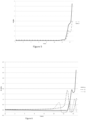
- the principle of the invention is based on the observation that the width of the groove arranged at the edge of a circumferential groove has a strong impact on the grip of the tire. Indeed, the excess pressures created in the contact area decrease, or even disappear, when the width of the groove increases.
- This invention is interpreted as an improvement of the patent FR3042441 where the positioning of a groove at the edge of a circumferential groove is repeated, but with a width adapted to minimize the overpressures created in the contact area.
- the ratio of the dynamic shear stiffness modulus of the material of the second portion of the sculpture block divided by the dynamic shear stiffness modulus of the material of the first axial portion of the sculpture block is within the interval [5;30], the shear stiffness moduli being measured at 23°C, at 10 Hz, and under an alternating shear deformation of 10% of the material of each portion.
- the grip of a tire when rolling on a ground obeys at least a double physical phenomenon of adhesion and indentation in the contact patch.
- the flexibility of the material allows it to follow the roughness of the ground to oppose the movement of the tire in the contact patch. This phenomenon is all the more amplified when the material is hysteretic.
- the reinforcement of the circumferential grooves by the material of the second portion of the tread block aims to avoid deformation and therefore too rapid wear of the grooves useful for maintaining effective drainage of water from the contact patch.
- the drying of the contact surface is a preliminary step to the adhesion/indentation phenomena described above, and therefore the presence of a water drainage network is necessary throughout the service life of the tire.
- the dynamic shear stiffness modulus of the reinforcement material must be significantly higher than that of the material of the first axial portion of the tread block. At a minimum, the ratio of the dynamic stiffness modulus of the material of the first axial portion divided by the dynamic stiffness modulus of the material of the second portion is greater than or equal to 5. This stiffness ratio of 5 between the two portions is sufficient to limit the deformations of the circumferential groove and groove. Beyond a ratio of 30, the sliding of the reinforcing material in the contact area can cause the second portion to wear too quickly.
- the materials of the two portions of a tread block are chosen to achieve a performance compromise between wet and dry grip and groove endurance.
- the soft material of the first axial portion which represents the majority of the total tread volume, is optimized for grip.
- the rigid material of the second portion of a tread block represents a very small proportion of the tread. The principle is to limit the volume of the material in the second portion of each tread block to just enough to avoid too great an impact on the tire's behavior.
- the invention can be implemented in various ways.
- the variants are linked on the one hand to the choice of “flexible” and “rigid” materials, and on the other hand to the geometry of the grooves and grooves as well as their positioning in the tread.
- the grooves have different depths P between the two adjacent portions of a sculpture block.
- the groove is arranged in the second rigid portion of a sculpture block, its width is defined in such a way that the groove extends over both portions. It follows that a part of the groove is found in the first axial portion which is made of a more flexible material.
- the radial depth of the groove is adapted from one portion to another taking into account the difference in rigidity.
- the groove could have an increasing depth P going axially from a first axial portion towards the second portion.
- the groove has a profile inclined relative to the tire's axis of rotation.
- the groove could also have a curved profile, or even a stepped profile.
- the groove has a depth P increasing axially from the second portion towards the first axial portion of a sculpture block.
- the material of the first axial portion of a sculpture block is an elastomeric mixture having a dynamic shear modulus G* less than or equal to 5 MPa, measured at 60°C and under alternating stress at 10 Hz.
- the geometry of the second portion(s) of a tread block may be wedge-shaped: this is the example chosen to explain the invention.
- the reinforced mixture may be arranged in the groove wall or in the thickness of the tread blocks.
- the second reinforcement portions may be independent or connected by a common base made of the same reinforcement material over all or part of the width of the tread.
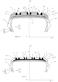
- the circumferential groove 6 is delimited axially by the walls (61, 62).
- the contact face of the groove 7 is delimited axially by the axial end 61 of the circumferential groove 6 merged with the axial end of the sculpture block 511, and a radial shoulder between the first axial portion 51 and the second axial portion 52.
- the groove 7 is delimited radially by a groove bottom, and has a depth P less than 2 mm, measured in a radial direction between the groove bottom 7 and the most radially outer contact face of the first axial portion 51.
- the contact face 9 comprises a part in the first axial portion 51, another part in the groove 7 and finally a last part in the rigid portion 52.
- the circumferential groove 6 has a depth P which goes from the contact surface 9 with the ground to the bottom of the circumferential groove 6.
- the groove 7 has a width L7, measured in the axial direction between the walls (71, 72) of the groove 7, one of the walls 72 of the groove 7 being merged with one of the walls of the sculpture block 511.
- FIG. 3 represents an embodiment of the invention where the second portion 52 takes the form of walls of the grooves 6. These walls are not connected to each other and are placed radially externally on the material of the first axial portion 51.
- the first axial portion 51 is made of a flexible elastomeric mixture, i.e. with a dynamic shear stiffness modulus of the order of 1.4 MPa, while the second portion 52 is much more rigid with a mixture having a dynamic shear stiffness modulus of the order of 25 MPa.
- the viscoelastic loss of the mixture of the first axial portion 51, Tg ⁇ is 0.17.
- the blocks located at the axial ends of the tread each have an axial width of 55 mm.
- the block in the center of the tread and the intermediate blocks between the axial ends and the center of the tread have an axial width of 28.7 mm.
Landscapes
- Engineering & Computer Science (AREA)
- Mechanical Engineering (AREA)
- Tires In General (AREA)
Claims (7)
- Reifen (1) mit einer Rotationsachse, beinhaltend zwei Wülste (2), zwei Flanken (3), die mit den Wülsten verbunden sind, einen Scheitel (4), der eine erste Seite aufweist, die mit dem radial äußeren Ende einer der zwei Flanken (3) verbunden ist, und eine zweite Seite aufweist, die mit dem radial äußeren Ende der anderen der zwei Flanken (3) verbunden ist, wobei der Scheitel (4) radial außenliegend zu einer Unterschicht (11) eine Lauffläche (5) umfasst, die Folgendes beinhaltet:o mindestens einen Profilblock (511), der eine Kontaktfläche (9) trägt, die dazu bestimmt ist, während des Rollens des Reifens mit der Fahrbahn in Kontakt zu kommen, wobei die Kontaktfläche (9) axial durch zwei axiale Enden des Profilblocks (511) begrenzt wird, wobei der Profilblock (511) Folgendes beinhaltet: einen ersten axialen Abschnitt (51), der sich axial über einen Teil der Gesamtbreite des Profilblocks (511) erstreckt und sich in Umfangsrichtung über mindestens 75 % des Umfangs des Reifens erstreckt, wobei der erste axiale Abschnitt (51) einen ersten axialen Abschnitt der Kontaktfläche trägt, wobei der erste axiale Abschnitt (51) ein Basismaterial beinhaltet; einen zweiten axialen Abschnitt (52), der sich axial über einen Teil der Gesamtbreite des Profilblocks (511) erstreckt und sich in Umfangsrichtung über mindestens 75 % des Umfangs des Reifens erstreckt, wobei der zweite axiale Abschnitt (52) einen zweiten axialen Abschnitt der Kontaktfläche (9) trägt, wobei der zweite axiale Abschnitt ein steifes Verstärkungsmaterial beinhaltet, dessen dynamisches Scherfestigkeitsmodul mindestens dreimal so groß wie der des Basismaterials ist;o mindestens eine Umfangsrille (6), die axial durch zwei axiale Enden (61, 62) begrenzt wird, wobei eines der axialen Enden (61, 62) der Umfangsrille (6) mit einem der axialen Enden des Profilblocks (511) zusammenfällt;o mindestens eine Nut (7), die in dem Profilblock (511) eingerichtet ist und eine Kontaktfläche der Nut (7) trägt, die dazu bestimmt ist, während des Rollens des Reifens mit der Fahrbahn in Kontakt zu kommen, wobei die Kontaktfläche der Nut (7) axial durch Folgendes begrenzt wird: das axiale Ende der Umfangsrille (6), das mit dem axialen Ende des Profilblocks (511) zusammenfällt, und eine radiale Schulter zwischen dem ersten axialen Abschnitt (51) und dem zweiten axialen Abschnitt (52), wobei die Nut (7) radial durch einen Nutboden begrenzt wird, wobei die Nut (7), gemessen entlang einer radialen Richtung zwischen dem Nutboden (7) und der radial äußersten Kontaktfläche des ersten axialen Abschnitts (51), eine Tiefe P kleiner als 2 mm aufweist,dadurch gekennzeichnet, dass die axiale Breite L7 der Nut (7) in dem Intervall [3 x L52, 1,01xL52] enthalten ist, wobei L7 die axiale Breite der Kontaktfläche der Nut (7) ist und L52 die axiale Breite der Kontaktfläche des zweiten axialen Abschnitts ist, und dass das Verhältnis des dynamischen Scherfestigkeitsmoduls des Materials des zweiten Abschnitts (52) des Profilblocks (511) zu dem dynamischen Scherfestigkeitsmodul des Materials des ersten axialen Abschnitts (51) des Profilsblocks (511) in dem Intervall [5;30] enthalten ist, wobei die Scherfestigkeitsmodule bei 23 °C, bei 10 Hz und unter einer Scherwechselverformung von 10 % des Materials jedes Abschnitts gemessen werden.
- Reifen (1) nach Anspruch 1, wobei die Nuten (7) von einem Abschnitt zum nächsten unterschiedliche Tiefen P aufweisen.
- Reifen (1) nach einem der Ansprüche 1 bis 2, wobei die Nut (7) ein in Bezug auf die Rotationsachse des Reifens geneigtes Profil aufweist.
- Reifen (1) nach einem der Ansprüche 1 bis 2, wobei die Nut (7) ein gebogenes Profil aufweist.
- Reifen nach einem der Ansprüche 1 bis 2, wobei die Nut (7) ein Stufenprofil aufweist.
- Reifen nach einem der Ansprüche 1 bis 5, wobei die Nut (7) von den ersten Abschnitten (51) axial hin zu den zweiten Abschnitten (52) eine zunehmende Tiefe P aufweist.
- Reifen nach einem der Ansprüche 1 bis 6, wobei das Material des ersten axialen Abschnitts (51) eine Elastomermischung ist, die, gemessen bei 60 °C und unter einer Wechselbeanspruchung bei 10 Hz, ein dynamisches Schermodul G* kleiner als oder gleich 5 MPa aufweist.
Applications Claiming Priority (2)
| Application Number | Priority Date | Filing Date | Title |
|---|---|---|---|
| FR2011019A FR3115498B1 (fr) | 2020-10-28 | 2020-10-28 | Pneumatique avec une bande de roulement comportant des rainures circonférentielles renforcées |
| PCT/FR2021/051857 WO2022090652A1 (fr) | 2020-10-28 | 2021-10-22 | Pneumatique avec une bande de roulement comportant des rainures circonférentielles renforcées |
Publications (2)
| Publication Number | Publication Date |
|---|---|
| EP4237261A1 EP4237261A1 (de) | 2023-09-06 |
| EP4237261B1 true EP4237261B1 (de) | 2025-04-16 |
Family
ID=74125447
Family Applications (1)
| Application Number | Title | Priority Date | Filing Date |
|---|---|---|---|
| EP21810404.0A Active EP4237261B1 (de) | 2020-10-28 | 2021-10-22 | Reifen mit einer lauffläche mit verstärkten umfangsrillen |
Country Status (3)
| Country | Link |
|---|---|
| EP (1) | EP4237261B1 (de) |
| FR (1) | FR3115498B1 (de) |
| WO (1) | WO2022090652A1 (de) |
Families Citing this family (1)
| Publication number | Priority date | Publication date | Assignee | Title |
|---|---|---|---|---|
| WO2025132979A1 (fr) | 2023-12-21 | 2025-06-26 | Compagnie Generale Des Etablissements Michelin | Pneumatique optimisé en résistance au roulement |
Family Cites Families (6)
| Publication number | Priority date | Publication date | Assignee | Title |
|---|---|---|---|---|
| WO2005063509A1 (en) | 2003-12-30 | 2005-07-14 | Pirelli Pneumatici S.P.A. | Pneumatic tire and process for its manufacture |
| BRPI0722345C8 (pt) * | 2007-12-24 | 2020-12-22 | Pirelli | pneu |
| EP3288782B1 (de) * | 2015-04-28 | 2019-08-07 | Compagnie Générale des Etablissements Michelin | Reifen mit einer lauffläche mit verstärkungselementen |
| FR3042441A1 (fr) | 2015-10-20 | 2017-04-21 | Michelin & Cie | Pneumatique avec bande de roulement comportant des secteurs renforces et des gorges auto-entretenues |
| JP2019094024A (ja) * | 2017-11-27 | 2019-06-20 | Toyo Tire株式会社 | 空気入りタイヤ |
| JP7030509B2 (ja) * | 2017-12-27 | 2022-03-07 | Toyo Tire株式会社 | 空気入りタイヤ |
-
2020
- 2020-10-28 FR FR2011019A patent/FR3115498B1/fr active Active
-
2021
- 2021-10-22 EP EP21810404.0A patent/EP4237261B1/de active Active
- 2021-10-22 WO PCT/FR2021/051857 patent/WO2022090652A1/fr not_active Ceased
Also Published As
| Publication number | Publication date |
|---|---|
| FR3115498B1 (fr) | 2022-10-14 |
| FR3115498A1 (fr) | 2022-04-29 |
| WO2022090652A1 (fr) | 2022-05-05 |
| EP4237261A1 (de) | 2023-09-06 |
Similar Documents
| Publication | Publication Date | Title |
|---|---|---|
| EP3707013B1 (de) | Reifen mit einer lauffläche, die geneigte lamellen mit einem spezifischen material kombiniert | |
| EP3713776B1 (de) | Reifen für personenkraftwagen | |
| EP3707012B1 (de) | Reifen mit einer lauffläche, die geneigte lamellen mit einem spezifischen material kombiniert | |
| EP3310591B1 (de) | Luftreifen mit einem deckenbereich mit einem verstärkungselement und einer lauffläche mit hoher bodenhaftung | |
| WO2018002487A1 (fr) | Pneumatique avec une bande de roulement comportant des elements de renforcement | |
| EP4171971B1 (de) | Reifen mit einer lauffläche, die für die griffigkeit auf nassboden im abgenutzen zustand optimiert ist | |
| EP4237261B1 (de) | Reifen mit einer lauffläche mit verstärkten umfangsrillen | |
| EP3554853B1 (de) | Reifen mit einer lauffläche mit verstärkungselementen | |
| EP3390099B1 (de) | Reifen mit verbesserten eigenschaften der abriebfestigkeit und des rollwiderstands | |
| EP3390100A1 (de) | Reifen mit verbesserten eigenschaften der abnutzung und des rollwiderstands | |
| EP4228905B1 (de) | Reifen mit einer lauffläche aus mehreren elastomerverbindungen | |
| EP3390095B1 (de) | Reifen mit verbesserten abnutzungs- und rollwiderstandseigenschaften | |
| EP3390098B1 (de) | Reifen mit verbesserten eigenschaften der abnutzung und des rollwiderstands | |
| EP3898270B1 (de) | Optimierter reifen für transporter | |
| EP3898271B1 (de) | Optimierter reifen für transporter | |
| EP3898269B1 (de) | Optimierter reifen für transporter | |
| EP3390103A1 (de) | Reifen mit verbesserten abnutzungseigenschaften und verbessertem rollwiderstand | |
| EP3368340B1 (de) | Reifen mit einer lauffläche mit verstärkten sektoren und einem lamellenlaufflächenmuster | |
| EP3390104A1 (de) | Reifen mit verbesserten abnutzungs- und rollwiderstandseigenschaften | |
| FR3161387A1 (fr) | Pneumatique comprenant un sous-creux réduit et une bande de roulement silencieuse | |
| WO2020128209A1 (fr) | Pneumatique pour camionnette optimise | |
| FR3157270A1 (fr) | Pneumatique optimisé en comportement routier sans dégrader la résistance au roulement | |
| FR3037530A1 (fr) | Pneumatique avec un sommet comportant une nappe de renforcement et une bande de roulement a forte adherence | |
| WO2020128208A1 (fr) | Pneumatique pour camionnette optimise | |
| WO2020128207A1 (fr) | Pneumatique pour camionnette optimise |
Legal Events
| Date | Code | Title | Description |
|---|---|---|---|
| STAA | Information on the status of an ep patent application or granted ep patent |
Free format text: STATUS: UNKNOWN |
|
| STAA | Information on the status of an ep patent application or granted ep patent |
Free format text: STATUS: THE INTERNATIONAL PUBLICATION HAS BEEN MADE |
|
| PUAI | Public reference made under article 153(3) epc to a published international application that has entered the european phase |
Free format text: ORIGINAL CODE: 0009012 |
|
| STAA | Information on the status of an ep patent application or granted ep patent |
Free format text: STATUS: REQUEST FOR EXAMINATION WAS MADE |
|
| 17P | Request for examination filed |
Effective date: 20230530 |
|
| AK | Designated contracting states |
Kind code of ref document: A1 Designated state(s): AL AT BE BG CH CY CZ DE DK EE ES FI FR GB GR HR HU IE IS IT LI LT LU LV MC MK MT NL NO PL PT RO RS SE SI SK SM TR |
|
| DAV | Request for validation of the european patent (deleted) | ||
| DAX | Request for extension of the european patent (deleted) | ||
| GRAP | Despatch of communication of intention to grant a patent |
Free format text: ORIGINAL CODE: EPIDOSNIGR1 |
|
| STAA | Information on the status of an ep patent application or granted ep patent |
Free format text: STATUS: GRANT OF PATENT IS INTENDED |
|
| INTG | Intention to grant announced |
Effective date: 20240610 |
|
| GRAS | Grant fee paid |
Free format text: ORIGINAL CODE: EPIDOSNIGR3 |
|
| GRAJ | Information related to disapproval of communication of intention to grant by the applicant or resumption of examination proceedings by the epo deleted |
Free format text: ORIGINAL CODE: EPIDOSDIGR1 |
|
| GRAL | Information related to payment of fee for publishing/printing deleted |
Free format text: ORIGINAL CODE: EPIDOSDIGR3 |
|
| STAA | Information on the status of an ep patent application or granted ep patent |
Free format text: STATUS: REQUEST FOR EXAMINATION WAS MADE |
|
| GRAP | Despatch of communication of intention to grant a patent |
Free format text: ORIGINAL CODE: EPIDOSNIGR1 |
|
| STAA | Information on the status of an ep patent application or granted ep patent |
Free format text: STATUS: GRANT OF PATENT IS INTENDED |
|
| INTC | Intention to grant announced (deleted) | ||
| INTG | Intention to grant announced |
Effective date: 20241204 |
|
| GRAA | (expected) grant |
Free format text: ORIGINAL CODE: 0009210 |
|
| STAA | Information on the status of an ep patent application or granted ep patent |
Free format text: STATUS: THE PATENT HAS BEEN GRANTED |
|
| AK | Designated contracting states |
Kind code of ref document: B1 Designated state(s): AL AT BE BG CH CY CZ DE DK EE ES FI FR GB GR HR HU IE IS IT LI LT LU LV MC MK MT NL NO PL PT RO RS SE SI SK SM TR |
|
| REG | Reference to a national code |
Ref country code: GB Ref legal event code: FG4D Free format text: NOT ENGLISH |
|
| REG | Reference to a national code |
Ref country code: CH Ref legal event code: EP |
|
| REG | Reference to a national code |
Ref country code: IE Ref legal event code: FG4D Free format text: LANGUAGE OF EP DOCUMENT: FRENCH |
|
| REG | Reference to a national code |
Ref country code: DE Ref legal event code: R096 Ref document number: 602021029323 Country of ref document: DE |
|
| REG | Reference to a national code |
Ref country code: NL Ref legal event code: MP Effective date: 20250416 |
|
| PG25 | Lapsed in a contracting state [announced via postgrant information from national office to epo] |
Ref country code: NL Free format text: LAPSE BECAUSE OF FAILURE TO SUBMIT A TRANSLATION OF THE DESCRIPTION OR TO PAY THE FEE WITHIN THE PRESCRIBED TIME-LIMIT Effective date: 20250416 |
|
| REG | Reference to a national code |
Ref country code: AT Ref legal event code: MK05 Ref document number: 1785361 Country of ref document: AT Kind code of ref document: T Effective date: 20250416 |
|
| PG25 | Lapsed in a contracting state [announced via postgrant information from national office to epo] |
Ref country code: FI Free format text: LAPSE BECAUSE OF FAILURE TO SUBMIT A TRANSLATION OF THE DESCRIPTION OR TO PAY THE FEE WITHIN THE PRESCRIBED TIME-LIMIT Effective date: 20250416 Ref country code: PT Free format text: LAPSE BECAUSE OF FAILURE TO SUBMIT A TRANSLATION OF THE DESCRIPTION OR TO PAY THE FEE WITHIN THE PRESCRIBED TIME-LIMIT Effective date: 20250818 Ref country code: ES Free format text: LAPSE BECAUSE OF FAILURE TO SUBMIT A TRANSLATION OF THE DESCRIPTION OR TO PAY THE FEE WITHIN THE PRESCRIBED TIME-LIMIT Effective date: 20250416 |
|
| REG | Reference to a national code |
Ref country code: LT Ref legal event code: MG9D |
|
| PG25 | Lapsed in a contracting state [announced via postgrant information from national office to epo] |
Ref country code: NO Free format text: LAPSE BECAUSE OF FAILURE TO SUBMIT A TRANSLATION OF THE DESCRIPTION OR TO PAY THE FEE WITHIN THE PRESCRIBED TIME-LIMIT Effective date: 20250716 Ref country code: GR Free format text: LAPSE BECAUSE OF FAILURE TO SUBMIT A TRANSLATION OF THE DESCRIPTION OR TO PAY THE FEE WITHIN THE PRESCRIBED TIME-LIMIT Effective date: 20250717 |
|
| PG25 | Lapsed in a contracting state [announced via postgrant information from national office to epo] |
Ref country code: PL Free format text: LAPSE BECAUSE OF FAILURE TO SUBMIT A TRANSLATION OF THE DESCRIPTION OR TO PAY THE FEE WITHIN THE PRESCRIBED TIME-LIMIT Effective date: 20250416 |
|
| PG25 | Lapsed in a contracting state [announced via postgrant information from national office to epo] |
Ref country code: BG Free format text: LAPSE BECAUSE OF FAILURE TO SUBMIT A TRANSLATION OF THE DESCRIPTION OR TO PAY THE FEE WITHIN THE PRESCRIBED TIME-LIMIT Effective date: 20250416 |
|
| PG25 | Lapsed in a contracting state [announced via postgrant information from national office to epo] |
Ref country code: HR Free format text: LAPSE BECAUSE OF FAILURE TO SUBMIT A TRANSLATION OF THE DESCRIPTION OR TO PAY THE FEE WITHIN THE PRESCRIBED TIME-LIMIT Effective date: 20250416 |
|
| PG25 | Lapsed in a contracting state [announced via postgrant information from national office to epo] |
Ref country code: AT Free format text: LAPSE BECAUSE OF FAILURE TO SUBMIT A TRANSLATION OF THE DESCRIPTION OR TO PAY THE FEE WITHIN THE PRESCRIBED TIME-LIMIT Effective date: 20250416 |
|
| PG25 | Lapsed in a contracting state [announced via postgrant information from national office to epo] |
Ref country code: RS Free format text: LAPSE BECAUSE OF FAILURE TO SUBMIT A TRANSLATION OF THE DESCRIPTION OR TO PAY THE FEE WITHIN THE PRESCRIBED TIME-LIMIT Effective date: 20250716 |
|
| PG25 | Lapsed in a contracting state [announced via postgrant information from national office to epo] |
Ref country code: IS Free format text: LAPSE BECAUSE OF FAILURE TO SUBMIT A TRANSLATION OF THE DESCRIPTION OR TO PAY THE FEE WITHIN THE PRESCRIBED TIME-LIMIT Effective date: 20250816 |
|
| PG25 | Lapsed in a contracting state [announced via postgrant information from national office to epo] |
Ref country code: LV Free format text: LAPSE BECAUSE OF FAILURE TO SUBMIT A TRANSLATION OF THE DESCRIPTION OR TO PAY THE FEE WITHIN THE PRESCRIBED TIME-LIMIT Effective date: 20250416 |