EP4168282B1 - Hydraulikaggregat, insbesondere zur steuerung und regelung eines bremsdrucks in einem bremskreis einer elektronisch schlupfregelbaren bremsanlage eines kraftfahrzeugs und verfahren zur montage eines hydraulikaggregats - Google Patents
Hydraulikaggregat, insbesondere zur steuerung und regelung eines bremsdrucks in einem bremskreis einer elektronisch schlupfregelbaren bremsanlage eines kraftfahrzeugs und verfahren zur montage eines hydraulikaggregats Download PDFInfo
- Publication number
- EP4168282B1 EP4168282B1 EP21715128.1A EP21715128A EP4168282B1 EP 4168282 B1 EP4168282 B1 EP 4168282B1 EP 21715128 A EP21715128 A EP 21715128A EP 4168282 B1 EP4168282 B1 EP 4168282B1
- Authority
- EP
- European Patent Office
- Prior art keywords
- pump housing
- electronic control
- hydraulic assembly
- motor
- assembly according
- Prior art date
- Legal status (The legal status is an assumption and is not a legal conclusion. Google has not performed a legal analysis and makes no representation as to the accuracy of the status listed.)
- Active
Links
Images
Classifications
-
- B—PERFORMING OPERATIONS; TRANSPORTING
- B60—VEHICLES IN GENERAL
- B60T—VEHICLE BRAKE CONTROL SYSTEMS OR PARTS THEREOF; BRAKE CONTROL SYSTEMS OR PARTS THEREOF, IN GENERAL; ARRANGEMENT OF BRAKING ELEMENTS ON VEHICLES IN GENERAL; PORTABLE DEVICES FOR PREVENTING UNWANTED MOVEMENT OF VEHICLES; VEHICLE MODIFICATIONS TO FACILITATE COOLING OF BRAKES
- B60T13/00—Transmitting braking action from initiating means to ultimate brake actuator with power assistance or drive; Brake systems incorporating such transmitting means, e.g. air-pressure brake systems
- B60T13/10—Transmitting braking action from initiating means to ultimate brake actuator with power assistance or drive; Brake systems incorporating such transmitting means, e.g. air-pressure brake systems with fluid assistance, drive, or release
- B60T13/66—Electrical control in fluid-pressure brake systems
- B60T13/662—Electrical control in fluid-pressure brake systems characterised by specified functions of the control system components
-
- B—PERFORMING OPERATIONS; TRANSPORTING
- B60—VEHICLES IN GENERAL
- B60T—VEHICLE BRAKE CONTROL SYSTEMS OR PARTS THEREOF; BRAKE CONTROL SYSTEMS OR PARTS THEREOF, IN GENERAL; ARRANGEMENT OF BRAKING ELEMENTS ON VEHICLES IN GENERAL; PORTABLE DEVICES FOR PREVENTING UNWANTED MOVEMENT OF VEHICLES; VEHICLE MODIFICATIONS TO FACILITATE COOLING OF BRAKES
- B60T8/00—Arrangements for adjusting wheel-braking force to meet varying vehicular or ground-surface conditions, e.g. limiting or varying distribution of braking force
- B60T8/32—Arrangements for adjusting wheel-braking force to meet varying vehicular or ground-surface conditions, e.g. limiting or varying distribution of braking force responsive to a speed condition, e.g. acceleration or deceleration
- B60T8/34—Arrangements for adjusting wheel-braking force to meet varying vehicular or ground-surface conditions, e.g. limiting or varying distribution of braking force responsive to a speed condition, e.g. acceleration or deceleration having a fluid pressure regulator responsive to a speed condition
- B60T8/36—Arrangements for adjusting wheel-braking force to meet varying vehicular or ground-surface conditions, e.g. limiting or varying distribution of braking force responsive to a speed condition, e.g. acceleration or deceleration having a fluid pressure regulator responsive to a speed condition including a pilot valve responding to an electromagnetic force
- B60T8/3615—Electromagnetic valves specially adapted for anti-lock brake and traction control systems
- B60T8/3675—Electromagnetic valves specially adapted for anti-lock brake and traction control systems integrated in modulator units
- B60T8/368—Electromagnetic valves specially adapted for anti-lock brake and traction control systems integrated in modulator units combined with other mechanical components, e.g. pump units, master cylinders
-
- B—PERFORMING OPERATIONS; TRANSPORTING
- B60—VEHICLES IN GENERAL
- B60T—VEHICLE BRAKE CONTROL SYSTEMS OR PARTS THEREOF; BRAKE CONTROL SYSTEMS OR PARTS THEREOF, IN GENERAL; ARRANGEMENT OF BRAKING ELEMENTS ON VEHICLES IN GENERAL; PORTABLE DEVICES FOR PREVENTING UNWANTED MOVEMENT OF VEHICLES; VEHICLE MODIFICATIONS TO FACILITATE COOLING OF BRAKES
- B60T11/00—Transmitting braking action from initiating means to ultimate brake actuator without power assistance or drive or where such assistance or drive is irrelevant
- B60T11/10—Transmitting braking action from initiating means to ultimate brake actuator without power assistance or drive or where such assistance or drive is irrelevant transmitting by fluid means, e.g. hydraulic
- B60T11/16—Master control, e.g. master cylinders
- B60T11/236—Piston sealing arrangements
-
- B—PERFORMING OPERATIONS; TRANSPORTING
- B60—VEHICLES IN GENERAL
- B60T—VEHICLE BRAKE CONTROL SYSTEMS OR PARTS THEREOF; BRAKE CONTROL SYSTEMS OR PARTS THEREOF, IN GENERAL; ARRANGEMENT OF BRAKING ELEMENTS ON VEHICLES IN GENERAL; PORTABLE DEVICES FOR PREVENTING UNWANTED MOVEMENT OF VEHICLES; VEHICLE MODIFICATIONS TO FACILITATE COOLING OF BRAKES
- B60T17/00—Component parts, details, or accessories of power brake systems not covered by groups B60T8/00, B60T13/00 or B60T15/00, or presenting other characteristic features
-
- B—PERFORMING OPERATIONS; TRANSPORTING
- B60—VEHICLES IN GENERAL
- B60T—VEHICLE BRAKE CONTROL SYSTEMS OR PARTS THEREOF; BRAKE CONTROL SYSTEMS OR PARTS THEREOF, IN GENERAL; ARRANGEMENT OF BRAKING ELEMENTS ON VEHICLES IN GENERAL; PORTABLE DEVICES FOR PREVENTING UNWANTED MOVEMENT OF VEHICLES; VEHICLE MODIFICATIONS TO FACILITATE COOLING OF BRAKES
- B60T8/00—Arrangements for adjusting wheel-braking force to meet varying vehicular or ground-surface conditions, e.g. limiting or varying distribution of braking force
- B60T8/17—Using electrical or electronic regulation means to control braking
- B60T8/176—Brake regulation specially adapted to prevent excessive wheel slip during vehicle deceleration, e.g. ABS
-
- B—PERFORMING OPERATIONS; TRANSPORTING
- B60—VEHICLES IN GENERAL
- B60T—VEHICLE BRAKE CONTROL SYSTEMS OR PARTS THEREOF; BRAKE CONTROL SYSTEMS OR PARTS THEREOF, IN GENERAL; ARRANGEMENT OF BRAKING ELEMENTS ON VEHICLES IN GENERAL; PORTABLE DEVICES FOR PREVENTING UNWANTED MOVEMENT OF VEHICLES; VEHICLE MODIFICATIONS TO FACILITATE COOLING OF BRAKES
- B60T2270/00—Further aspects of brake control systems not otherwise provided for
- B60T2270/10—ABS control systems
-
- B—PERFORMING OPERATIONS; TRANSPORTING
- B60—VEHICLES IN GENERAL
- B60Y—INDEXING SCHEME RELATING TO ASPECTS CROSS-CUTTING VEHICLE TECHNOLOGY
- B60Y2400/00—Special features of vehicle units
- B60Y2400/81—Braking systems
-
- B—PERFORMING OPERATIONS; TRANSPORTING
- B60—VEHICLES IN GENERAL
- B60Y—INDEXING SCHEME RELATING TO ASPECTS CROSS-CUTTING VEHICLE TECHNOLOGY
- B60Y2410/00—Constructional features of vehicle sub-units
- B60Y2410/10—Housings
Definitions
- the invention relates to a hydraulic unit, in particular for controlling and regulating a brake pressure in a brake circuit of an electronically slip-controllable brake system of a motor vehicle according to the features of the preamble of claim 1 and further to a method for assembling a hydraulic unit according to the features of the preamble of claim 14.
- the brake pressures in the wheel brakes of a vehicle can be electronically controlled in such a way that any wheel slip that occurs on the vehicle's associated wheels only occurs for a short period of time. In this way, the vehicle remains steerable during braking, does not become unstable and can still be braked within a short braking distance.
- Electronically controlled slip brake systems are also able to initiate and control braking processes independently, i.e. without driver involvement, depending on a traffic situation that is likely to cause an accident or a critical driving condition.
- Electronically controlled slip brake systems are also important in the technical implementation of piloted or automated driving.
- the mentioned brake pressure control within an electronically controlled brake system is carried out by a so-called hydraulic unit, as is known for example from the DE 10 2017 218 648 A1 is already known.
- This well-known hydraulic unit comprises a pump housing which is equipped with, among other things, a drivable brake pressure generator. The latter is operated by a motor via a rotating motor shaft. In this context, the electrical control of the motor is carried out as required by an electronic control unit.
- the motor and the electronic control unit are arranged on opposite sides of the pump housing.
- the motor shaft is rotatably mounted inside a shaft bore which penetrates the pump housing from the side on which the motor is arranged to the opposite side on which the electronic control unit is arranged.
- the angle of rotation of the motor shaft is recorded by a sensor device consisting of a signal transmitter rotating with the motor shaft and a signal receiver fixed in the electronic control unit.
- the shaft bore is sealed from the interior of the electronic control unit by a sealing device so that a potential pressure medium leak in the pump housing cannot penetrate through the shaft bore into the interior of the electronic control unit and cause malfunctions there.
- the present invention differs from this prior art, among other things, through the use of an insert seal to seal the shaft bore to the electronic control unit.
- This insert seal is arranged in a seal receptacle formed on the pump housing and is subjected to a preloading force by a preloading device when the electronic control unit is attached to the pump housing.
- Insert seals are available in a wide range of designs at low cost on the market, are easy to handle in the production process and the production quality can be easily checked during assembly, for example visually, using cameras or mechanically, using measuring probes.
- an insert seal can easily compensate for an assembly-related offset of the electronic control unit relative to the pump housing.
- a mechanically pre-stressed insert seal absorbs thermally induced expansion tolerances and dimensional tolerances between the housing of the electronic control unit, which is usually made of plastic, and the pump housing, which is usually made of an aluminum alloy.
- the sealing properties of an insert seal can be predetermined under known installation conditions and can therefore be adapted to the specific application as required. For example, by designing the material, shape and dimensions of the insert seal, the pre-tensioning device and the seal holder, axial and radial forces can be determined with which the insert seal is pressed against the boundaries of the associated seal holder in the pre-tensioned state.
- insert seals have the advantage that complex dosing devices and process time for curing an introduced sealing compound are saved and that the assemblies sealed against each other can be more easily separated from each other and, if necessary, exchanged.
- the insert seal is subjected to an axial force directed in the direction of a longitudinal axis of the motor shaft by the mechanical pre-tensioning device. This axial force ensures a reliable sealing effect of the insert seal under changing ambient conditions.
- a device housing of the electronic control unit comprises an intermediate floor facing the pump housing, from which the pre-tensioning device protrudes in the direction of a longitudinal axis of the motor shaft.
- An intermediate floor allows the interior of an electronic control unit to be divided into an installation space facing the pump housing for coil assemblies of solenoid valves and a circuit board space facing away from the pump housing for accommodating the electronic control.
- a pre-tensioning device which is preferably designed in one piece with the housing base of the device housing, has the advantage that it can be mounted on the pump housing together with the electronic control unit and therefore does not require any additional parts or assembly.
- the effective axial force with which the pre-tensioning device presses on the insert seal can be set within narrow tolerance limits and maintained in large-scale production.
- the pretensioning device is designed in the form of a hollow body closed on one side, the closed end of which is located inside the electronic control unit and into the open end of which an end of the motor shaft remote from the motor projects in sections.
- This design allows the motor shaft mounted in the pump housing to be extended beyond the pump housing into the interior of the electronic control unit and to arrange a signal transmitter at the end of the motor shaft that is necessary for detecting the angle of rotation of the motor shaft.
- the associated signal receiver can be placed directly opposite it on the circuit board of the electronic control unit, so that separate contact means for electrically contacting this signal receiver with the circuit board are eliminated.
- the seal receptacle is a recess that surrounds the shaft bore on the circumference and is open towards the outside of the pump housing.
- One base of this recess forms a shoulder on which the insert seal is supported in the axial direction.
- a seal made of elastic plastic material or an elastic plastic composite material can be used as an insert seal. Together with differently designed seal cross-sections, this allows the greatest possible freedom in designing the seal properties to suit the respective application.
- the proposed sealing concept is particularly suitable for hydraulic units of vehicle braking systems that are equipped with an electronically commutated motor.
- Such motors offer advantages in terms of service life, dynamics and size, but their electrical control must be carried out depending on the angle of rotation of the motor shaft or the rotor. The latter is detected by means of a signal transmitter on the motor shaft and a cooperating signal receiver in the electronic control unit.
- This electronic control unit is reliably sealed against the pump housing pressurized with a pressure medium by the sealing device designed according to the invention, without affecting the signal transmission between the signal transmitter and the signal receiver.
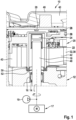
- This drawing comprises a single figure in which a region of a hydraulic unit essential to the invention is shown in longitudinal section.
- the area of a hydraulic unit (10) shown in the single figure includes, among other things, a section of the pump housing (12) in which a section of a shaft bore (14) is located.
- a rolling bearing (16) is arranged, which supports a motor shaft (18) so that it can rotate inside the shaft bore (14).
- Other bearings required for this cannot be seen in the figure due to the limited section.
- a motor (17) by which the motor shaft (18) can be driven to rotate is only indicated schematically in the figure.
- a brake pressure generator (19) actuated by the rotating motor shaft (18), for example a radial piston pump driven by an eccentric attached to the motor shaft (18).
- the end of the motor shaft (18) which is remote from the motor extends beyond the edge of the pump housing (12) into the hollow interior of an electronic control unit (20) arranged on this side of the pump housing (12).
- a cup-shaped holding element (22) which is closed on one side is attached to the protruding end of the motor shaft (18).
- a signal transmitter (24) is accommodated therein at a distance from an end face of the motor shaft (18). The latter is connected to the holding element (22) in a rotationally fixed manner, e.g. by means of an adhesive connection.
- the signal transmitter (24) is a magnet whose magnetic field can be evaluated by a signal receiver (26) for the purpose of detecting the angle of rotation of the motor shaft (18).
- this signal receiver (26) is arranged opposite the signal transmitter (24) on a circuit board (28) of the electronic control unit (20) and is contacted with an electrical circuit attached thereto.
- the holding element (22) equipped with the signal generator (24) is coupled in a rotationally fixed manner to the motor shaft (18) and thus follows the rotational movement of this motor shaft (18).
- the electronic control unit (20) has a device housing (32) preferably made of plastic. This is attached to the pump housing (12) and comprises an interior of the device housing (32) enclosing peripheral wall. This interior space is divided by an intermediate floor (36) running transversely to the peripheral wall into a coil space (38) facing the pump housing (12) and an electronics space (40) facing away from it, which accommodates the circuit board (28) of the control electronics.
- the intermediate floor (36) forms a frame component which is provided with openings which connect the two spaces to one another.
- Coil assemblies (42) of solenoid valves for pressure medium control are housed in the coil space (38) of the device housing (32). These coil assemblies (42) consist of a magnetic coil arranged under a valve cap. The pressure medium controlling part of the hydraulic valves is anchored in associated recesses on the pump housing (12) in a way that cannot be seen and protrudes into the interior of these magnetic coils with a valve dome that protrudes beyond the edge of the pump housing (12). A valve element that can be actuated by the magnetic field of the coils is housed in the valve dome (not shown). Electrical contact elements are attached to the intermediate floor (28), via which the electrical contact between the coil assemblies (42) and the circuit board (28) of the electronic control unit (20) is made.
- This circuit board (28) is preferably aligned at a distance plane-parallel to the intermediate floor (36) in the electronics compartment (40) of the electronic control unit (20) and is equipped with electronic components. Conductor tracks on the circuit board (28) connect the components to form an electrical circuit, by means of which a brake pressure can be regulated in accordance with requirements.
- the electronics compartment (40) is open to the environment on its side facing away from the pump housing (12) and is closed there by a housing cover (46).
- This housing cover (46) protects the interior of the electronic control unit (20) from contamination or moisture penetrating from the environment of the hydraulic unit (10).
- it is made of metal and is shaped in three dimensions.
- a pre-tensioning device (48) in the form of a cup or hollow body closed on one side is preferably formed in one piece with the intermediate base (36). Its closed end is located in the electronics compartment (40) of the device housing (32), and the motor shaft (18) with the attached holding element (22) and the signal transmitter (24) accommodated therein protrudes in sections into its open end.
- the pre-tensioning device (48) is perpendicular and thus in the direction of a longitudinal axis L of the motor shaft (18) from the intermediate base (36) and penetrates the coil compartment (38) when the control device (20) is installed.
- the pre-tensioning device (48) presses in the area of its open end onto an insert seal (50) which is arranged in a stepped seal receptacle (52) of the pump housing (12).
- This seal holder (52) encloses the shaft bore (14) and, in the embodiment, is open to the surroundings of the pump housing and to the shaft bore (14).
- a base of the seal holder (52) forms a shoulder on which the insert seal (50) rests axially.
- the insert seal (50) mentioned is ring-shaped and can be made from an elastic plastic composite material or an elastic plastic, for example EPDM or silicone foam. Depending on the application, it can be solid or hollow in cross-section and have a circular, oval, polygonal or, for example, Z-shaped contour. In the embodiment shown, the insert seal (50) is solid and has a double-T profile.
- the axial extent and the radial extension of the pre-tensioning device (48) is structurally matched to the dimensions of the pump housing (12) and the device housing (32) in such a way that the end face of the pre-tensioning device (48) applies a predetermined axial force to the insert seal (50) when the control device (20) is attached to the pump housing (12).
- the insert seal (50) can be arranged separately from the electronic control unit (20) in the seal holder (52) before this electronic control unit (20) is mounted on the pump housing (12) or that the insert seal (50) is first pre-mounted on the pre-tensioning device (48) of the electronic control unit (12) and then mounted together with the electronic control unit (20) on the pump housing (12). Both variants are conceivable as alternatives.
Landscapes
- Engineering & Computer Science (AREA)
- Transportation (AREA)
- Mechanical Engineering (AREA)
- Physics & Mathematics (AREA)
- Electromagnetism (AREA)
- Fluid Mechanics (AREA)
- Regulating Braking Force (AREA)
- Gasket Seals (AREA)
- Braking Systems And Boosters (AREA)
- Braking Arrangements (AREA)
- Details Of Reciprocating Pumps (AREA)
Description
- Die Erfindung betrifft ein Hydraulikaggregat, insbesondere zur Steuerung und Regelung eines Bremsdrucks in einem Bremskreis einer elektronisch schlupfregelbaren Bremsanlage eines Kraftfahrzeugs nach den Merkmalen des Oberbegriffs des Anspruchs 1 und weiterhin ein Verfahren zur Montage eines Hydraulikaggregats nach den Merkmalen des Oberbegriffs des Anspruchs 14.
- Elektronisch schlupfregelbare Bremsanlagen in Kraftfahrzeugen sind hinlänglich bekannt. Sie tragen erwiesenermaßen zur Erhöhung der Sicherheit im Straßenverkehr bei und sind deshalb inzwischen in vielen Ländern gesetzlich vorgeschrieben.
- Mit elektronisch schlupfregelbaren Bremsanlagen sind die Bremsdrücke in den Radbremsen eines Fahrzeugs elektronisch derart regelbar, dass ein an den zugeordneten Rädern des Fahrzeugs auftretender Radschlupf nur für einen kurzen Zeitraum auftritt. Auf diese Weise bleibt das Fahrzeug während Bremsvorgängen lenkbar, gerät in keinen instabilen Fahrzustand und lässt sich dennoch auf kurzem Bremsweg abbremsen. Elektronisch schlupfregelbare Fahrzeugbremsanlagen sind zudem dazu imstande Bremsvorgänge in Abhängigkeit einer unfallträchtigen Verkehrssituation oder eines kritischen Fahrzustands selbstständig, d.h. ohne Fahrerbeteiligung einzuleiten und zu regeln. Weiterhin kommt elektronisch schlupfregelbaren Bremsanlagen bei der technischen Umsetzung eines pilotierten bzw. automatisierten Fahrbetriebs Bedeutung zu.
- Die erwähnte Bremsdruckregelung innerhalb einer elektronisch schlupfregelbaren Bremsanlage erfolgt durch ein sogenanntes Hydraulikaggregat, wie es beispielsweise aus der
DE 10 2017 218 648 A1 bereits bekannt ist. - Dieses bekannte Hydraulikaggregat umfasst ein Pumpengehäuse, das u.a. mit einem antreibbaren Bremsdruckerzeuger bestückt ist. Letzterer wird von einem Motor über eine rotierend angetriebene Motorwelle betätigt. Die elektrische Ansteuerung des Motors wird in diesem Zusammenhang bedarfsgerecht von einem elektronischen Steuergerät vorgenommen.
- Bei dem bekannten Hydraulikaggregat sind der Motor sowie das elektronische Steuergerät auf einander gegenüberliegenden Seiten des Pumpengehäuses angeordnet. Die Motorwelle ist drehbar im Inneren einer Wellenbohrung gelagert, welche das Pumpengehäuse von der Seite, an welcher der Motor angeordnet ist, bis zu der dazu gegenüberliegenden Seite, an welcher das elektronische Steuergerät angeordnet ist, durchdringt. Mit einer Sensoreinrichtung aus einem mit der Motorwelle umlaufenden Signalgeber und einem im elektronischen Steuergerät ortsfest aufgenommenen Signalempfänger wird der Drehwinkel der Motorwelle erfasst. Über eine Dichtungsvorrichtung ist die Wellenbohrung gegenüber dem Inneren des elektronischen Steuergeräts abgedichtet, so dass eine potenzielle Druckmittelleckage im Pumpengehäuse über die Wellenbohrung nicht in das Innere des elektronischen Steuergeräts vordringen und dort Störungen verursachen kann.
- Die vorliegende Erfindung unterscheidet sich von diesem Stand der Technik u.a. durch die Verwendung einer Einlegedichtung zur Abdichtung der Wellenbohrung zum elektronischen Steuergerät. Diese Einlegedichtung ist in einer am Pumpengehäuse ausgebildeten Dichtungsaufnahme angeordnet und wird von einer Vorspanneinrichtung mit einer Vorspannkraft beaufschlagt, wenn das elektronische Steuergerät am Pumpengehäuse befestigt ist.
- Weiterhin bekannt ist aus der
US 2004/144 248 A1 ein Verfahren zur Montage eines Hydraulikaggregats, bei dem eine Dichtungsvorrichtung von einem Abstützelement, gegen axiales Verschieben gesichert, in einer Dichtungsaufnahme angeordnet ist. - Einlegedichtungen sind in vielfältiger Ausführung kostengünstig am Markt verfügbar, sind im Fertigungsprozess einfach handhabbar und die Fertigungsqualität ist montagebegleitend problemlos zu prüfen, beispielsweise optisch, anhand von Kameras oder mechanisch, durch Messtaster. Zudem ist mit einer Einlegedichtung ein montagebedingter Versatz des elektronischen Steuergeräts relativ zum Pumpengehäuse leicht auszugleichen. Eine mechanisch vorgespannte Einlegdichtung nimmt thermisch bedingte Ausdehnungstoleranzen sowie Maßtoleranzen zwischen dem Gehäuse des elektronischen Steuergeräts, das üblicherweise aus Kunststoff hergestellt ist und dem Pumpengehäuse, welches üblicherweise aus einer Aluminiumlegierung besteht, auf.
- Weiterhin sind die Dichtungseigenschaften einer Einlegdichtung unter bekannten Einbaubedingungen vorherbestimmbar und lassen sich somit an einen jeweiligen Anwendungsfall bedarfsgerecht anpassen. Beispielsweise sind durch eine konstruktive Abstimmung von Material, Gestalt und Abmessungen der Einlegedichtung, der Vorspanneinrichtung und der Dichtungsaufnahme Axial- und Radialkräfte festlegbar mit welchen die Einlegedichtung im vorgespannten Zustand gegen die Begrenzungen der zugeordneten Dichtungsaufnahme gedrückt wird.
- Insbesondere gegenüber Flüssigdichtungen haben Einlegedichtungen den Vorteil, dass aufwändige Dosiereinrichtungen sowie Prozesszeit zur Aushärtung einer eingebrachten Dichtungsmasse eingespart und dass die gegeneinander abgedichteten Baugruppen einfacher voneinander gelöst und ggf. gegenseitig ausgetauscht werden können.
- Weitere Vorteile oder vorteilhafte Weiterbildungen der Erfindung ergeben sich aus den Unteransprüchen oder aus der nachfolgenden Beschreibung.
- In einer vorteilhaften Weiterbildung der Erfindung ist die Einlegedichtung von der mechanischen Vorspanneinrichtung mit einer in Richtung einer Längsachse der Motorwelle gerichteten Axialkraft beaufschlagt. Diese Axialkraft gewährleistet eine zuverlässige Dichtungswirkung der Einlegedichtung unter wechselnden Umgebungsbedingungen.
- Weiterhin vorteilhaft ist es, wenn ein Gerätegehäuse des elektronischen Steuergeräts einen dem Pumpengehäuse zugewandten Zwischenboden umfasst, von dem die Vorspanneinrichtung in Richtung einer Längsachse der Motorwelle absteht. Durch einen Zwischenboden lässt sich der Innenraum eines elektronischen Steuergeräts in einen dem Pumpengehäuse zugewandten Einbauraum für Spulenbaugruppen von Magnetventilen und in einen vom Pumpengehäuse abgewandten Platinenraum zur Aufnahme der elektronischen Steuerung unterteilen.
- Eine Vorspanneinrichtung, die bevorzugt in einem Stück mit dem Gehäuseboden des Gerätegehäuses ausgebildet ist, hat den Vorteil, dass sie zusammen mit dem elektronischen Steuergerät an das Pumpengehäuse montiert werden kann und somit keinen zusätzlichen Teile- bzw. Montagebedarf erfordert. Zudem kann dadurch die wirksame Axialkraft, mit welcher die Vorspanneinrichtung auf die Einlegedichtung drückt, konstruktiv in engen Toleranzgrenzen eingestellt und in der Großserie eingehalten werden.
- Bevorzugt ist die Vorspanneinrichtung in Gestalt eines einseitig geschlossenen Hohlkörpers ausgebildet, dessen geschlossenes Ende sich im Inneren des elektronischen Steuergeräts befindet und in dessen offenes Ende ein motorfernes Ende der Motorwelle abschnittsweise hineinragt.
- Diese Ausgestaltung gestattet es die im Pumpengehäuse gelagerte Motorwelle über das Pumpengehäuse hinaus bis in das Innere des elektronischen Steuergeräts hinein zu verlängern und am Ende der Motorwelle einen zur Erfassung des Drehwinkels der Motorwelle notwendigen Signalgeber anzuordnen. Der zugeordnete Signalempfänger lässt sich unmittelbar gegenüberliegend dazu direkt auf der Leiterplatte des elektronischen Steuergeräts platzieren, so dass separate Kontaktmittel zur elektrischen Kontaktierung dieses Signalempfängers mit der Leiterplatte eingespart werden.
- In einer weiteren vorteilhaften Weiterbildung der Erfindung ist die Dichtungsaufnahme eine die Wellenbohrung umfangseitig umschließende, zur Umgebung des Pumpengehäuses hin außen offene Ausnehmung. Ein Grund dieser Ausnehmung bildet eine Schulter aus, an welcher die Einlegedichtung in axialer Richtung abgestützt ist. Durch die Befestigung des elektronischen Steuergeräts am Pumpengehäuse ist sichergestellt, dass die daran ausgebildete Vorspanneinrichtung mit der Dichtungsaufnahme des Pumpengehäuses fluchtet.
- Als Einlegedichtung kann eine Dichtung aus elastischem Kunststoffmaterial oder aus einem elastischem Kunststoffverbundmaterial eingesetzt werden. Zusammen mit unterschiedlich gestalteten Dichtungsquerschnitten ermöglicht dies eine größtmögliche Freiheit bei der konstruktiven Abstimmung der Dichtungseigenschaften auf den jeweiligen Anwendungsfall.
- Das vorgeschlagene Dichtungskonzept ist insbesondere geeignet für Hydraulikaggregate von Fahrzeugbremsanlagen, die mit einem elektronisch kommutierten Motor ausgestattet sind. Derartige Motoren bieten Vorteile hinsichtlich Lebensdauer, Dynamik und Baugröße, allerdings muss deren elektrische Ansteuerung in Abhängigkeit des Drehwinkels der Motorwelle bzw. des Rotors vorgenommen werden. Letzterer wird mittels eines Signalgebers auf der Motorwelle sowie eines damit zusammenwirkenden Signalempfängers im elektronischen Steuergerät erfasst.
- Dieses elektronische Steuergerät ist durch die erfindungsgemäß ausgeführte Dichtungsvorrichtung gegenüber dem mit einem Druckmittel beaufschlagten Pumpengehäuse zuverlässig abgedichtet, ohne dass dabei die Signalübertragung zwischen dem Signalgeber und dem Signalempfänger beeinträchtigt wird.
- Hinsichtlich eines potenziell möglichen Störungsfalls ist schließlich noch die durch die Erfindung geschaffene Möglichkeit zu einer zerstörungsfreien Zerlegung des Hydraulikaggregats in seine Komponenten sowie zu einem Austausch des elektronischen Steuergeräts oder des Pumpengehäuses von Bedeutung.
- Die Erfindung ist in der Zeichnung dargestellt und wird in nachfolgender Beschreibung detailliert erläutert.
- Diese Zeichnung umfasst eine einzige Figur, in welcher ein für die Erfindung wesentlicher Bereich eines Hydraulikaggregats im Längsschnitt gezeigt ist.
- Der in der einzigen Figur dargestellte Bereich eines Hydraulikaggregats (10) umfasst u.a. einen Ausschnitt des Pumpengehäuses (12) in dem sich ein Abschnitt einer Wellenbohrung (14) befindet. In diesem Abschnitt der Wellenbohrung (14) ist ein Wälzlager (16) angeordnet, welches eine Motorwelle (18) drehbar im Inneren der Wellenbohrung (14) lagert. Weitere hierfür notwendige Lager sind aufgrund des begrenzten Ausschnitts in der Figur nicht zu erkennen. Lediglich schematisch in der Figur angedeutet ist ein Motor (17), durch welchen die Motorwelle (18) zu einer Rotationsbewegung antreibbar ist. Ebenfalls nur schematisch eingezeichnet ist ein von der rotierenden Motorwelle (18) betätigter Bremsdruckerzeuger (19), beispielsweise eine von einem auf der Motorwelle (18) angebrachten Exzenter getriebene Radialkolbenpumpe.
- Die Motorwelle (18) ragt mit ihrem motorfernen Wellenende, über die Begrenzung des Pumpengehäuses (12) hinaus in das hohle Innere eines auf dieser Seite des Pumpengehäuses (12) angeordneten elektronischen Steuergeräts (20) hinein. Auf dem vorstehenden Ende der Motorwelle (18) ist ein einseitig geschlossenes, becherförmiges Halteelement (22) angebracht. Darin ist mit Abstand zu einer Stirnfläche der Motorwelle (18) ein Signalgeber (24) aufgenommen. Letzterer ist drehfest mit dem Haltelement (22) verbunden, bspw. mittels einer Klebeverbindung. Beim Signalgeber (24) handelt es sich um einen Magneten, dessen Magnetfeld von einem Signalempfänger (26) zum Zweck einer Erfassung des Drehwinkels der Motorwelle (18) auswertbar ist. Dieser Signalempfänger (26) ist hierfür, gegenüberliegend zum Signalgeber (24), auf einer Leiterplatte (28) des elektronischen Steuergeräts (20) angeordnet und mit einer darauf angebrachten elektrischen Schaltung kontaktiert.
- Das mit dem Signalgeber (24) bestückte Halteelement (22) ist drehfest mit der Motorwelle (18) gekoppelt und folgt damit der Rotationsbewegung dieser Motorwelle (18).
- Das elektronische Steuergerät (20) weist ein vorzugsweise aus Kunststoff bestehende Gerätegehäuse (32) auf. Dieses ist am Pumpengehäuse (12) festgelegt und umfasst eine, einen Innenraum des Gerätegehäuses (32) umschließende Umfangswand. Dieser Innenraum wird von einem quer zur Umfangswand verlaufenden Zwischenboden (36) in einen dem Pumpengehäuse (12) zugewandten Spulenraum (38) und in einen davon abgewandt liegenden, die Leiterplatte (28) der Steuerelektronik aufnehmenden, Elektronikraum (40) unterteilt. In bevorzugter Ausführungsform bildet der Zwischenboden (36) ein Rahmenbauteil, das mit Durchbrüchen versehen ist, welche die beiden Räume miteinander verbinden.
- Im Spulenraum (38) des Gerätegehäuses (32) sind Spulenbaugruppen (42) von Magnetventilen zur Druckmittelsteuerung untergebracht. Diese Spulenbaugruppen (42) bestehen aus einer unter einer Ventilkappe angeordneten Magnetspule. Der druckmittelsteuernde Teil der Hydraulikventile ist nicht erkennbar in zugeordneten Ausnehmungen am Pumpengehäuse (12) verankert und ragt mit jeweils einem über die Begrenzung des Pumpengehäuses (12) vorstehenden Ventildom in das Innere dieser Magnetspulen hinein. Im Ventildom ist ein vom magnetischen Feld der Spulen betätigbares Ventilglied untergebracht (nicht dargestellt). Am Zwischenboden (28) sind elektrische Kontaktelemente angebracht, über welche die elektrische Kontaktierung der Spulenbaugruppen (42) mit der Leiterplatte (28) des elektronischen Steuergeräts (20) erfolgt.
- Diese Leiterplatte (28) ist im Elektronikraum (40) des elektronischen Steuergeräts (20) bevorzugt mit Abstand planparallel zum Zwischenboden (36) ausgerichtet und mit elektronischen Bauelementen bestückt. Auf der Leiterplatte (28) vorhandene Leiterbahnen verbinden die Bauelemente zu einer elektrischen Schaltung, durch welche eine an den Bedarf angepassten Regelung eines Bremsdrucks möglich ist.
- Der Elektronikraum (40) ist auf seiner vom Pumpengehäuse (12) abgewandten Seite zur Umgebung hin offen und wird dort von einem Gehäusedeckel (46) verschlossen. Von diesem Gehäusedeckel (46) wird das Innere des elektronischen Steuergeräts (20) vor Verunreinigungen bzw. eindringender Feuchtigkeit aus der Umgebung des Hydraulikaggregats (10) geschützt. Er besteht beim Ausführungsbeispiel aus Metall und ist beispielhaft 3-dimensionial geformt.
- Bevorzugt einteilig mit dem Zwischenboden (36) ausgebildet ist eine Vorspanneinrichtung (48) in Gestalt eines einseitig verschlossenen Bechers bzw. Hohlkörpers. Dessen geschlossenes Ende befindet sich im Elektronikraum (40) des Gerätegehäuses (32), in sein offenes Ende ragt die Motorwelle (18) mit dem angebauten Haltelement (22) und dem darin aufgenommenen Signalgeber (24) abschnittsweise hinein. Die Vorspanneinrichtung (48) steht senkrecht und damit in Richtung einer Längsachse L der Motorwelle (18) vom Zwischenboden (36) ab und durchdringt im angebauten Zustand des Steuergeräts (20) den Spulenraum (38). Mit der Stirnfläche eines gegenüber dem Spulenraum (38) vorstehenden Abschnitts drückt die Vorspanneinrichtung (48) im Bereich ihres offenen Endes auf eine Einlegedichtung (50), welche in einer gestuft ausgeführten Dichtungsaufnahme (52) des Pumpengehäuses (12) angeordnet ist. Diese Dichtungsaufnahme (52) umschließt die Wellenbohrung (14) und ist beim Ausführungsbeispiel zur Umgebung des Pumpengehäuses sowie zur Wellenbohrung (14) hin offen. Darüber hinaus bildet ein Grund der Dichtungsaufnahme (52) eine Schulter aus, auf welcher die Einlegedichtung (50) axial aufliegt.
- Die erwähnte Einlegedichtung (50) an sich ist ringförmig gestaltet und kann aus einem elastischen Kunststoffverbundmaterial oder einem elastischen Kunststoff hergestellt sein, beispielsweise aus EPDM oder Silikonschaum. Sie kann je nach Anwendungsfall im Querschnitt massiv oder hohl ausgeführt werden und eine kreisrunde, ovale, mehreckige oder bspw. z-förmige Kontur haben. Beim dargestellten Ausführungsbeispiel ist die Einlegedichtung (50) beispielhaft massiv ausgeführt und hat ein Doppel-T-Profil.
- Die axiale Erstreckung und die radiale Ausdehnung der Vorspanneinrichtung (48) ist konstruktiv derart auf die Abmessungen des Pumpengehäuses (12) und des Gerätegehäuses (32) abgestimmt, dass die Stirnfläche der Vorspanneinrichtung (48) die Einlegedichtung (50) mit einer vorbestimmten Axialkraft beaufschlagt, wenn das Steuergerät (20) an das Pumpengehäuse (12) angebaut ist.
- Von dieser Axialkraft wird die Einlegedichtung (50) elastisch derart verformt, dass Letztere sich zuverlässig an die Begrenzungen der Dichtungsaufnahme (52) am Pumpengehäuse (12) anlegt. Die Einlegedichtung (50) verhindert damit zusammen mit der Vorspanneinrichtung (48), dass eine Druckmittelleckage aus dem Pumpengehäuse (12) über die Wellenbohrung (14) in das Innere des Steuergeräts (20) vordringen und dort Störungen verursachen kann.
- Es ist an dieser Stelle anzumerken, dass die Einlegedichtung (50) getrennt vom elektronischen Steuergerät (20) in der Dichtungsaufnahme (52) angeordnet werden kann bevor dieses elektronische Steuergerät (20) an das Pumpengehäuse (12) montiert wird oder dass die Einlegedichtung (50) zunächst an der Vorspanneinrichtung (48) des elektronischen Steuergeräts (12) vormontiert und anschließend zusammen mit dem elektronischen Steuergerät (20) an das Pumpengehäuse (12) montiert wird. Beide Varianten sind alternativ vorstellbar.
Claims (14)
- Hydraulikaggregat (10), insbesondere zur Steuerung und Regelung eines Bremsdrucks in einem Bremskreis einer elektronisch schlupfregelbaren Bremsanlage eines Kraftfahrzeugs,mit einem Pumpengehäuse (12), das mit einem betätigbaren Bremsdruckerzeuger (19) bestückt ist,mit einem Motor (17) zum Antrieb des Bremsdruckerzeugers (19) undmit einem elektronischen Steuergerät (20) zu einer bedarfsgerechten elektrischen Ansteuerung des Motors (17),wobei der Motor (17) und das Steuergerät (20) auf einander gegenüberliegenden Seiten des Pumpengehäuses (12) angeordnet sind, wobei am Pumpengehäuse (12) eine Wellenbohrung (14) ausgebildet ist, die von einer ersten Seite des Pumpengehäuses (12) an welcher der Motor (17) angeordnet ist zu einer zweiten Seite des Pumpengehäuses (12) an welcher das elektronische Steuergerät (20) befestigt ist durchgeht,wobei im Inneren der Wellenbohrung (14) eine vom Motor (17) zu einer Rotationsbewegung antreibbare Motorwelle (18) drehbar angeordnet ist und wobei zu einer Abdichtung der Wellenbohrung (14) gegenüber einem Innenraum des elektronischen Steuergeräts (20) eine Dichtungsvorrichtung vorgesehen ist, dadurch gekennzeichnet,dass die Dichtungsvorrichtung eine in einer Dichtungsaufnahme (52) des Pumpengehäuses (12) angeordnete Einlegedichtung (50) umfasst, welche von einer Vorspanneinrichtung (48) mit einer mechanischen Vorspannkraft beaufschlagt ist, wenn das elektronische Steuergerät (20) am Pumpengehäuse (12) fest verankert ist.
- Hydraulikaggregat nach Anspruch 1, dadurch gekennzeichnet,
dass die Einlegedichtung (50) von der mechanischen Vorspanneinrichtung (48) mit einer in Richtung einer Längsachse L der Motorwelle (18) wirkenden Axialkraft beaufschlagt ist. - Hydraulikaggregat nach Anspruch 1 oder 2, dadurch gekennzeichnet, dass ein Gerätegehäuse (32) des Steuergeräts (20) einen Zwischenboden (36) umfasst von dem die Vorspanneinrichtung (48), vorzugsweise in Richtung einer Längsachse L der Motorwelle (18), absteht.
- Hydraulikaggregat nach Anspruch 3, dadurch gekennzeichnet,
dass die Vorspanneinrichtung (48) in einem Stück mit dem Zwischenboden (36) des Gerätegehäuses (32) ausgebildet ist. - Hydraulikaggregat nach einem der Ansprüche 1 bis 4,
dadurch gekennzeichnet,
dass die Vorspanneinrichtung (48) in Gestalt eines einseitig geschlossenen Hohlkörpers ausgebildet ist, dessen geschlossenes Ende sich im Inneren des elektronischen Steuergeräts (20) befindet und in dessen offenes Ende ein motorfernes Ende der Motorwelle (18) abschnittsweise hineinragt. - Hydraulikaggregat nach einem der Ansprüche 1 bis 5,
dadurch gekennzeichnet,
dass die Vorspanneinrichtung (48) mit einer Stirnfläche ihres offenen Endes auf die Einlegedichtung (50) drückt. - Hydraulikaggregat nach einem der Ansprüche 1 bis 6,
dadurch gekennzeichnet,
dass die Einlegedichtung (50) aus einem formelastischem Kunststoffmaterial oder aus einem formelastischen Kunststoffverbundmaterial besteht. - Hydraulikaggregat nach einem der Ansprüche 1 bis 7,
dadurch gekennzeichnet,
dass die Einlegedichtung (50) mit einem massiven Querschnitt oder mit einem Hohlquerschnitt ausgeführt ist und eine kreisrunde, ovale, mehreckige oder eine z-förmige Außenkontur aufweist. - Hydraulikaggregat nach einem der Ansprüche 1 bis 8,
dadurch gekennzeichnet,
dass die Dichtungsaufnahme (52) eine die Wellenbohrung (14) umfangseitig umschließende, zur Umgebung des Pumpengehäuses (12) hin offene Ausnehmung ist, welche eine Schulter aufweist, an welcher die Einlegedichtung (50) in Richtung einer Längsachse L der Motorwelle (18) abgestützt ist. - Hydraulikaggregat nach Anspruch 9, dadurch gekennzeichnet,
dass die Dichtungsaufnahme (52) zur Wellenbohrung (14) hin offen ist. - Hydraulikaggregat nach Anspruch 9 oder 10, dadurch gekennzeichnet, dass die Einlegedichtung (50) im vorgespannten Zustand an einer Begrenzung der Dichtungsaufnahme (52) mit radialer und/oder mit axialer Vorspannung anliegt.
- Hydraulikaggregat nach einem der Ansprüche 1 bis 11,wobei zu einer Erfassung und elektronischen Auswertung des Drehwinkels der Motorwelle (18) durch das elektronische Steuergerät (20) ein mit der Motorwelle (18) rotierender Signalgeber (24) sowie ein zugeordneter ortsfest angeordneter Signalempfänger (26) vorgesehen sind,dadurch gekennzeichnet,dass der Signalempfänger (26) unmittelbar auf einer Leiterplatte (28) des elektronischen Steuergeräts (20) angeordnet und elektrisch kontaktiert ist.
- Hydraulikaggregat nach einem der Ansprüche 1 bis 12,
dadurch gekennzeichnet,
dass der Motor (17) elektrisch kommutiert ist. - Verfahren zur Montage eines Hydraulikaggregats (10) nach den Merkmalen eines der Ansprüche 1 bis 13, dadurch gekennzeichnet,dass die Einlegedichtung (50) in die am Pumpengehäuse (12) angeordnete Dichtungsaufnahme (52) eingelegt wird, bevor das elektronische Steuergerät (20) am Pumpengehäuse (12) verankert wird oderdass die Einlegdichtung (50) an der Vorspanneinrichtung (48) des elektronischen Steuergeräts (12) vormontiert und anschließend zusammen mit dem elektronischen Steuergerät (20) an das Pumpengehäuse (12) montiert wird.
Applications Claiming Priority (2)
| Application Number | Priority Date | Filing Date | Title |
|---|---|---|---|
| DE102020207505.0A DE102020207505A1 (de) | 2020-06-17 | 2020-06-17 | Hydraulikaggregat, insbesondere zur Steuerung und Regelung eines Bremsdrucks in einem Bremskreis einer elektronisch schlupfregelbaren Bremsanlage eines Kraftfahrzeugs und Verfahren zur Montage eines Hydraulikaggregats |
| PCT/DE2021/100190 WO2021254552A1 (de) | 2020-06-17 | 2021-02-25 | Hydraulikaggregat, insbesondere zur steuerung und regelung eines bremsdrucks in einem bremskreis einer elektronisch schlupfregelbaren bremsanlage eines kraftfahrzeugs und verfahren zur montage eines hydraulikaggregats |
Publications (2)
| Publication Number | Publication Date |
|---|---|
| EP4168282A1 EP4168282A1 (de) | 2023-04-26 |
| EP4168282B1 true EP4168282B1 (de) | 2024-04-24 |
Family
ID=75277771
Family Applications (1)
| Application Number | Title | Priority Date | Filing Date |
|---|---|---|---|
| EP21715128.1A Active EP4168282B1 (de) | 2020-06-17 | 2021-02-25 | Hydraulikaggregat, insbesondere zur steuerung und regelung eines bremsdrucks in einem bremskreis einer elektronisch schlupfregelbaren bremsanlage eines kraftfahrzeugs und verfahren zur montage eines hydraulikaggregats |
Country Status (8)
| Country | Link |
|---|---|
| US (1) | US12391229B2 (de) |
| EP (1) | EP4168282B1 (de) |
| JP (1) | JP7490092B2 (de) |
| KR (1) | KR102860766B1 (de) |
| CN (1) | CN115003574B (de) |
| DE (2) | DE102020207505A1 (de) |
| MX (1) | MX2022016541A (de) |
| WO (1) | WO2021254552A1 (de) |
Families Citing this family (1)
| Publication number | Priority date | Publication date | Assignee | Title |
|---|---|---|---|---|
| KR20220159552A (ko) * | 2021-05-25 | 2022-12-05 | 현대모비스 주식회사 | 브레이크 시스템의 펌프하우징 레이아웃 |
Family Cites Families (10)
| Publication number | Priority date | Publication date | Assignee | Title |
|---|---|---|---|---|
| GB2266752A (en) | 1992-05-08 | 1993-11-10 | Lucas Ind Plc | Master cylinder |
| DE19747850A1 (de) * | 1997-07-30 | 1999-02-04 | Bosch Gmbh Robert | Kolbenpumpe |
| WO2003016116A1 (de) | 2001-08-13 | 2003-02-27 | Continental Teves Ag & Co. Ohg | Elektrohydraulische druckregelvorrichtung |
| JP4292813B2 (ja) * | 2003-01-29 | 2009-07-08 | 株式会社アドヴィックス | マスタシリンダ、該マスタシリンダ用シールリテーナ、及び該シールリテーナの装着方法 |
| CN101121405A (zh) * | 2006-08-11 | 2008-02-13 | 株式会社爱德克斯 | 用于车辆制动系统的制动压力控制单元 |
| JP5598222B2 (ja) * | 2010-09-30 | 2014-10-01 | 株式会社アドヴィックス | 軸シール装置とそれを用いたポンプ装置及びブレーキ液圧制御装置 |
| US9174620B2 (en) * | 2013-01-21 | 2015-11-03 | Kelsey-Hayes Company | Slip control braking pump having a high pressure sealing structure |
| DE102016105232A1 (de) * | 2016-03-21 | 2017-09-21 | Ipgate Ag | Betätigungsvorrichtung für ein hydraulisches Betätigungssystem, insbesondere eine Kraftfahrzeugbremse oder einen elektrifizierten Kupplungs- und Gangsteller |
| DE102017218648A1 (de) | 2017-10-19 | 2019-04-25 | Robert Bosch Gmbh | Antriebsaggregat, insbesondere Hydraulikaggregat einer elektronisch schlupfregelbaren Fahrzeugbremsanlage |
| JP2019119270A (ja) | 2017-12-28 | 2019-07-22 | 株式会社アドヴィックス | 液圧制御装置 |
-
2020
- 2020-06-17 DE DE102020207505.0A patent/DE102020207505A1/de not_active Withdrawn
-
2021
- 2021-02-25 MX MX2022016541A patent/MX2022016541A/es unknown
- 2021-02-25 US US18/009,824 patent/US12391229B2/en active Active
- 2021-02-25 DE DE112021003284.4T patent/DE112021003284A5/de active Pending
- 2021-02-25 CN CN202180009479.3A patent/CN115003574B/zh active Active
- 2021-02-25 EP EP21715128.1A patent/EP4168282B1/de active Active
- 2021-02-25 WO PCT/DE2021/100190 patent/WO2021254552A1/de not_active Ceased
- 2021-02-25 KR KR1020237001193A patent/KR102860766B1/ko active Active
- 2021-02-25 JP JP2022576192A patent/JP7490092B2/ja active Active
Also Published As
| Publication number | Publication date |
|---|---|
| US12391229B2 (en) | 2025-08-19 |
| CN115003574B (zh) | 2024-04-26 |
| JP7490092B2 (ja) | 2024-05-24 |
| KR102860766B1 (ko) | 2025-09-18 |
| KR20230028372A (ko) | 2023-02-28 |
| DE102020207505A1 (de) | 2021-12-23 |
| JP2023530649A (ja) | 2023-07-19 |
| US20230242086A1 (en) | 2023-08-03 |
| EP4168282A1 (de) | 2023-04-26 |
| CN115003574A (zh) | 2022-09-02 |
| WO2021254552A1 (de) | 2021-12-23 |
| DE112021003284A5 (de) | 2023-04-20 |
| MX2022016541A (es) | 2023-02-01 |
Similar Documents
| Publication | Publication Date | Title |
|---|---|---|
| EP3350044B1 (de) | Baugruppe mit einem bremszylinder und einem elektromechanischen bremskraftverstärker mit einer derartigen baugruppe | |
| DE102015222286A1 (de) | Hydraulikblock und Hydraulikaggregat | |
| WO2014086517A1 (de) | Hydropumpenaggregat für eine hydraulische fahrzeugbremsanlage, hydraulische fahrzeugbremsanlage mit einem derartigen hydropumpenaggregat und verfahren zur herstellung des hydropumpenaggregates | |
| EP0995036B1 (de) | Pumpeneinheit | |
| DE4445362A1 (de) | Kolbenpumpe | |
| EP3399187A1 (de) | Verfahren zur montage einer kolbenbaugruppe für eine druckerzeugungsvorrichtung eines bremssystems | |
| EP0914561B1 (de) | Kolbenpumpe mit rohrstück als laufbuchse | |
| EP2093127B1 (de) | Lenkgetriebe mit Sensor | |
| DE102011106626A1 (de) | Hochdynamischer Kurzbauantrieb | |
| WO2018104072A1 (de) | Hauptbremszylinderanordnung mit positionsgeberelement und dichtungsanordnung | |
| EP1901040A2 (de) | Berührungsloser Drehwinkelsensor | |
| DE19918124A1 (de) | Kolbenpumpe | |
| WO2021254552A1 (de) | Hydraulikaggregat, insbesondere zur steuerung und regelung eines bremsdrucks in einem bremskreis einer elektronisch schlupfregelbaren bremsanlage eines kraftfahrzeugs und verfahren zur montage eines hydraulikaggregats | |
| DE102020204831A1 (de) | Elektronisch kommutierte Maschine, elektronisch schlupfregelbare Bremsanlage und Verfahren zur Herstellung einer elektronisch kommutierten Maschine | |
| EP2655881A1 (de) | Kolbenpumpe mit einer laufbuchse | |
| DE19732810A1 (de) | Rückschlagventil, insbesondere für eine Kolbenpumpe | |
| DE10140918A1 (de) | Motor-Pumpen-Aggregat, insbesondere für ein Kraftfahrzeugbremssystem | |
| DE19752346B4 (de) | Hydraulisch unterstützte Lenkvorrichtung für ein Kraftfahrzeug | |
| DE102015226054A1 (de) | Elektromotor mit einer mit der Motorwelle umlaufenden Magnetanordnung | |
| EP1390249A1 (de) | Lenkung für kraftfahrzeuge | |
| DE102008039280A1 (de) | Achsschenkelbolzenlagerung und Verfahren zur Montage einer solchen | |
| DE102022207362A1 (de) | Druckvorrichtung mit einem Planetengetriebe | |
| DE102013211647A1 (de) | Innenzahnradpumpe | |
| DE102024205165A1 (de) | Sensoreinrichtung zur Erfassung und Auswertung der Drehbewegung einer Aggregatwelle und Verfahren zur Herstellung einer Sensoreinrichtung | |
| DE102022209188A1 (de) | Druckvorrichtung mit einem Plungerkolben |
Legal Events
| Date | Code | Title | Description |
|---|---|---|---|
| STAA | Information on the status of an ep patent application or granted ep patent |
Free format text: STATUS: UNKNOWN |
|
| STAA | Information on the status of an ep patent application or granted ep patent |
Free format text: STATUS: THE INTERNATIONAL PUBLICATION HAS BEEN MADE |
|
| PUAI | Public reference made under article 153(3) epc to a published international application that has entered the european phase |
Free format text: ORIGINAL CODE: 0009012 |
|
| STAA | Information on the status of an ep patent application or granted ep patent |
Free format text: STATUS: REQUEST FOR EXAMINATION WAS MADE |
|
| 17P | Request for examination filed |
Effective date: 20230117 |
|
| AK | Designated contracting states |
Kind code of ref document: A1 Designated state(s): AL AT BE BG CH CY CZ DE DK EE ES FI FR GB GR HR HU IE IS IT LI LT LU LV MC MK MT NL NO PL PT RO RS SE SI SK SM TR |
|
| DAV | Request for validation of the european patent (deleted) | ||
| DAX | Request for extension of the european patent (deleted) | ||
| GRAP | Despatch of communication of intention to grant a patent |
Free format text: ORIGINAL CODE: EPIDOSNIGR1 |
|
| STAA | Information on the status of an ep patent application or granted ep patent |
Free format text: STATUS: GRANT OF PATENT IS INTENDED |
|
| INTG | Intention to grant announced |
Effective date: 20231215 |
|
| GRAS | Grant fee paid |
Free format text: ORIGINAL CODE: EPIDOSNIGR3 |
|
| GRAA | (expected) grant |
Free format text: ORIGINAL CODE: 0009210 |
|
| STAA | Information on the status of an ep patent application or granted ep patent |
Free format text: STATUS: THE PATENT HAS BEEN GRANTED |
|
| AK | Designated contracting states |
Kind code of ref document: B1 Designated state(s): AL AT BE BG CH CY CZ DE DK EE ES FI FR GB GR HR HU IE IS IT LI LT LU LV MC MK MT NL NO PL PT RO RS SE SI SK SM TR |
|
| REG | Reference to a national code |
Ref country code: GB Ref legal event code: FG4D Free format text: NOT ENGLISH |
|
| REG | Reference to a national code |
Ref country code: CH Ref legal event code: EP |
|
| REG | Reference to a national code |
Ref country code: DE Ref legal event code: R096 Ref document number: 502021003471 Country of ref document: DE |
|
| REG | Reference to a national code |
Ref country code: IE Ref legal event code: FG4D Free format text: LANGUAGE OF EP DOCUMENT: GERMAN |
|
| REG | Reference to a national code |
Ref country code: LT Ref legal event code: MG9D |
|
| REG | Reference to a national code |
Ref country code: NL Ref legal event code: MP Effective date: 20240424 |
|
| PG25 | Lapsed in a contracting state [announced via postgrant information from national office to epo] |
Ref country code: NL Free format text: LAPSE BECAUSE OF FAILURE TO SUBMIT A TRANSLATION OF THE DESCRIPTION OR TO PAY THE FEE WITHIN THE PRESCRIBED TIME-LIMIT Effective date: 20240424 |
|
| PG25 | Lapsed in a contracting state [announced via postgrant information from national office to epo] |
Ref country code: NL Free format text: LAPSE BECAUSE OF FAILURE TO SUBMIT A TRANSLATION OF THE DESCRIPTION OR TO PAY THE FEE WITHIN THE PRESCRIBED TIME-LIMIT Effective date: 20240424 |
|
| PG25 | Lapsed in a contracting state [announced via postgrant information from national office to epo] |
Ref country code: IS Free format text: LAPSE BECAUSE OF FAILURE TO SUBMIT A TRANSLATION OF THE DESCRIPTION OR TO PAY THE FEE WITHIN THE PRESCRIBED TIME-LIMIT Effective date: 20240824 |
|
| PG25 | Lapsed in a contracting state [announced via postgrant information from national office to epo] |
Ref country code: BG Free format text: LAPSE BECAUSE OF FAILURE TO SUBMIT A TRANSLATION OF THE DESCRIPTION OR TO PAY THE FEE WITHIN THE PRESCRIBED TIME-LIMIT Effective date: 20240424 |
|
| PG25 | Lapsed in a contracting state [announced via postgrant information from national office to epo] |
Ref country code: FI Free format text: LAPSE BECAUSE OF FAILURE TO SUBMIT A TRANSLATION OF THE DESCRIPTION OR TO PAY THE FEE WITHIN THE PRESCRIBED TIME-LIMIT Effective date: 20240424 Ref country code: HR Free format text: LAPSE BECAUSE OF FAILURE TO SUBMIT A TRANSLATION OF THE DESCRIPTION OR TO PAY THE FEE WITHIN THE PRESCRIBED TIME-LIMIT Effective date: 20240424 |
|
| PG25 | Lapsed in a contracting state [announced via postgrant information from national office to epo] |
Ref country code: GR Free format text: LAPSE BECAUSE OF FAILURE TO SUBMIT A TRANSLATION OF THE DESCRIPTION OR TO PAY THE FEE WITHIN THE PRESCRIBED TIME-LIMIT Effective date: 20240725 |
|
| PG25 | Lapsed in a contracting state [announced via postgrant information from national office to epo] |
Ref country code: PT Free format text: LAPSE BECAUSE OF FAILURE TO SUBMIT A TRANSLATION OF THE DESCRIPTION OR TO PAY THE FEE WITHIN THE PRESCRIBED TIME-LIMIT Effective date: 20240826 |
|
| PG25 | Lapsed in a contracting state [announced via postgrant information from national office to epo] |
Ref country code: ES Free format text: LAPSE BECAUSE OF FAILURE TO SUBMIT A TRANSLATION OF THE DESCRIPTION OR TO PAY THE FEE WITHIN THE PRESCRIBED TIME-LIMIT Effective date: 20240424 |
|
| PG25 | Lapsed in a contracting state [announced via postgrant information from national office to epo] |
Ref country code: PL Free format text: LAPSE BECAUSE OF FAILURE TO SUBMIT A TRANSLATION OF THE DESCRIPTION OR TO PAY THE FEE WITHIN THE PRESCRIBED TIME-LIMIT Effective date: 20240424 |
|
| PG25 | Lapsed in a contracting state [announced via postgrant information from national office to epo] |
Ref country code: LV Free format text: LAPSE BECAUSE OF FAILURE TO SUBMIT A TRANSLATION OF THE DESCRIPTION OR TO PAY THE FEE WITHIN THE PRESCRIBED TIME-LIMIT Effective date: 20240424 |
|
| PG25 | Lapsed in a contracting state [announced via postgrant information from national office to epo] |
Ref country code: PT Free format text: LAPSE BECAUSE OF FAILURE TO SUBMIT A TRANSLATION OF THE DESCRIPTION OR TO PAY THE FEE WITHIN THE PRESCRIBED TIME-LIMIT Effective date: 20240826 Ref country code: PL Free format text: LAPSE BECAUSE OF FAILURE TO SUBMIT A TRANSLATION OF THE DESCRIPTION OR TO PAY THE FEE WITHIN THE PRESCRIBED TIME-LIMIT Effective date: 20240424 Ref country code: NO Free format text: LAPSE BECAUSE OF FAILURE TO SUBMIT A TRANSLATION OF THE DESCRIPTION OR TO PAY THE FEE WITHIN THE PRESCRIBED TIME-LIMIT Effective date: 20240724 Ref country code: LV Free format text: LAPSE BECAUSE OF FAILURE TO SUBMIT A TRANSLATION OF THE DESCRIPTION OR TO PAY THE FEE WITHIN THE PRESCRIBED TIME-LIMIT Effective date: 20240424 Ref country code: IS Free format text: LAPSE BECAUSE OF FAILURE TO SUBMIT A TRANSLATION OF THE DESCRIPTION OR TO PAY THE FEE WITHIN THE PRESCRIBED TIME-LIMIT Effective date: 20240824 Ref country code: HR Free format text: LAPSE BECAUSE OF FAILURE TO SUBMIT A TRANSLATION OF THE DESCRIPTION OR TO PAY THE FEE WITHIN THE PRESCRIBED TIME-LIMIT Effective date: 20240424 Ref country code: GR Free format text: LAPSE BECAUSE OF FAILURE TO SUBMIT A TRANSLATION OF THE DESCRIPTION OR TO PAY THE FEE WITHIN THE PRESCRIBED TIME-LIMIT Effective date: 20240725 Ref country code: FI Free format text: LAPSE BECAUSE OF FAILURE TO SUBMIT A TRANSLATION OF THE DESCRIPTION OR TO PAY THE FEE WITHIN THE PRESCRIBED TIME-LIMIT Effective date: 20240424 Ref country code: ES Free format text: LAPSE BECAUSE OF FAILURE TO SUBMIT A TRANSLATION OF THE DESCRIPTION OR TO PAY THE FEE WITHIN THE PRESCRIBED TIME-LIMIT Effective date: 20240424 Ref country code: BG Free format text: LAPSE BECAUSE OF FAILURE TO SUBMIT A TRANSLATION OF THE DESCRIPTION OR TO PAY THE FEE WITHIN THE PRESCRIBED TIME-LIMIT Effective date: 20240424 Ref country code: RS Free format text: LAPSE BECAUSE OF FAILURE TO SUBMIT A TRANSLATION OF THE DESCRIPTION OR TO PAY THE FEE WITHIN THE PRESCRIBED TIME-LIMIT Effective date: 20240724 |
|
| PG25 | Lapsed in a contracting state [announced via postgrant information from national office to epo] |
Ref country code: DK Free format text: LAPSE BECAUSE OF FAILURE TO SUBMIT A TRANSLATION OF THE DESCRIPTION OR TO PAY THE FEE WITHIN THE PRESCRIBED TIME-LIMIT Effective date: 20240424 |
|
| PG25 | Lapsed in a contracting state [announced via postgrant information from national office to epo] |
Ref country code: EE Free format text: LAPSE BECAUSE OF FAILURE TO SUBMIT A TRANSLATION OF THE DESCRIPTION OR TO PAY THE FEE WITHIN THE PRESCRIBED TIME-LIMIT Effective date: 20240424 |
|
| PG25 | Lapsed in a contracting state [announced via postgrant information from national office to epo] |
Ref country code: CZ Free format text: LAPSE BECAUSE OF FAILURE TO SUBMIT A TRANSLATION OF THE DESCRIPTION OR TO PAY THE FEE WITHIN THE PRESCRIBED TIME-LIMIT Effective date: 20240424 |
|
| PG25 | Lapsed in a contracting state [announced via postgrant information from national office to epo] |
Ref country code: SK Free format text: LAPSE BECAUSE OF FAILURE TO SUBMIT A TRANSLATION OF THE DESCRIPTION OR TO PAY THE FEE WITHIN THE PRESCRIBED TIME-LIMIT Effective date: 20240424 Ref country code: RO Free format text: LAPSE BECAUSE OF FAILURE TO SUBMIT A TRANSLATION OF THE DESCRIPTION OR TO PAY THE FEE WITHIN THE PRESCRIBED TIME-LIMIT Effective date: 20240424 |
|
| REG | Reference to a national code |
Ref country code: DE Ref legal event code: R097 Ref document number: 502021003471 Country of ref document: DE |
|
| PG25 | Lapsed in a contracting state [announced via postgrant information from national office to epo] |
Ref country code: SM Free format text: LAPSE BECAUSE OF FAILURE TO SUBMIT A TRANSLATION OF THE DESCRIPTION OR TO PAY THE FEE WITHIN THE PRESCRIBED TIME-LIMIT Effective date: 20240424 |
|
| PG25 | Lapsed in a contracting state [announced via postgrant information from national office to epo] |
Ref country code: SM Free format text: LAPSE BECAUSE OF FAILURE TO SUBMIT A TRANSLATION OF THE DESCRIPTION OR TO PAY THE FEE WITHIN THE PRESCRIBED TIME-LIMIT Effective date: 20240424 Ref country code: SK Free format text: LAPSE BECAUSE OF FAILURE TO SUBMIT A TRANSLATION OF THE DESCRIPTION OR TO PAY THE FEE WITHIN THE PRESCRIBED TIME-LIMIT Effective date: 20240424 Ref country code: RO Free format text: LAPSE BECAUSE OF FAILURE TO SUBMIT A TRANSLATION OF THE DESCRIPTION OR TO PAY THE FEE WITHIN THE PRESCRIBED TIME-LIMIT Effective date: 20240424 Ref country code: EE Free format text: LAPSE BECAUSE OF FAILURE TO SUBMIT A TRANSLATION OF THE DESCRIPTION OR TO PAY THE FEE WITHIN THE PRESCRIBED TIME-LIMIT Effective date: 20240424 Ref country code: DK Free format text: LAPSE BECAUSE OF FAILURE TO SUBMIT A TRANSLATION OF THE DESCRIPTION OR TO PAY THE FEE WITHIN THE PRESCRIBED TIME-LIMIT Effective date: 20240424 Ref country code: CZ Free format text: LAPSE BECAUSE OF FAILURE TO SUBMIT A TRANSLATION OF THE DESCRIPTION OR TO PAY THE FEE WITHIN THE PRESCRIBED TIME-LIMIT Effective date: 20240424 |
|
| PLBE | No opposition filed within time limit |
Free format text: ORIGINAL CODE: 0009261 |
|
| STAA | Information on the status of an ep patent application or granted ep patent |
Free format text: STATUS: NO OPPOSITION FILED WITHIN TIME LIMIT |
|
| 26N | No opposition filed |
Effective date: 20250127 |
|
| PG25 | Lapsed in a contracting state [announced via postgrant information from national office to epo] |
Ref country code: SI Free format text: LAPSE BECAUSE OF FAILURE TO SUBMIT A TRANSLATION OF THE DESCRIPTION OR TO PAY THE FEE WITHIN THE PRESCRIBED TIME-LIMIT Effective date: 20240424 |
|
| PGFP | Annual fee paid to national office [announced via postgrant information from national office to epo] |
Ref country code: AT Payment date: 20250417 Year of fee payment: 5 |
|
| PGFP | Annual fee paid to national office [announced via postgrant information from national office to epo] |
Ref country code: DE Payment date: 20250422 Year of fee payment: 5 |
|
| PG25 | Lapsed in a contracting state [announced via postgrant information from national office to epo] |
Ref country code: SE Free format text: LAPSE BECAUSE OF FAILURE TO SUBMIT A TRANSLATION OF THE DESCRIPTION OR TO PAY THE FEE WITHIN THE PRESCRIBED TIME-LIMIT Effective date: 20240424 |
|
| PG25 | Lapsed in a contracting state [announced via postgrant information from national office to epo] |
Ref country code: MC Free format text: LAPSE BECAUSE OF FAILURE TO SUBMIT A TRANSLATION OF THE DESCRIPTION OR TO PAY THE FEE WITHIN THE PRESCRIBED TIME-LIMIT Effective date: 20240424 |
|
| REG | Reference to a national code |
Ref country code: CH Ref legal event code: PL |
|
| PG25 | Lapsed in a contracting state [announced via postgrant information from national office to epo] |
Ref country code: LU Free format text: LAPSE BECAUSE OF NON-PAYMENT OF DUE FEES Effective date: 20250225 |
|
| PG25 | Lapsed in a contracting state [announced via postgrant information from national office to epo] |
Ref country code: CH Free format text: LAPSE BECAUSE OF NON-PAYMENT OF DUE FEES Effective date: 20250228 |
|
| GBPC | Gb: european patent ceased through non-payment of renewal fee |
Effective date: 20250225 |
|
| REG | Reference to a national code |
Ref country code: BE Ref legal event code: MM Effective date: 20250228 |
|
| PG25 | Lapsed in a contracting state [announced via postgrant information from national office to epo] |
Ref country code: GB Free format text: LAPSE BECAUSE OF NON-PAYMENT OF DUE FEES Effective date: 20250225 |
|
| PG25 | Lapsed in a contracting state [announced via postgrant information from national office to epo] |
Ref country code: BE Free format text: LAPSE BECAUSE OF NON-PAYMENT OF DUE FEES Effective date: 20250228 |
|
| PG25 | Lapsed in a contracting state [announced via postgrant information from national office to epo] |
Ref country code: IE Free format text: LAPSE BECAUSE OF NON-PAYMENT OF DUE FEES Effective date: 20250225 |
|
| PG25 | Lapsed in a contracting state [announced via postgrant information from national office to epo] |
Ref country code: IT Free format text: LAPSE BECAUSE OF FAILURE TO SUBMIT A TRANSLATION OF THE DESCRIPTION OR TO PAY THE FEE WITHIN THE PRESCRIBED TIME-LIMIT Effective date: 20240424 |
|
| PGFP | Annual fee paid to national office [announced via postgrant information from national office to epo] |
Ref country code: FR Payment date: 20260219 Year of fee payment: 6 |