EP4164543B1 - Tordierinstrument - Google Patents
Tordierinstrument Download PDFInfo
- Publication number
- EP4164543B1 EP4164543B1 EP21746632.5A EP21746632A EP4164543B1 EP 4164543 B1 EP4164543 B1 EP 4164543B1 EP 21746632 A EP21746632 A EP 21746632A EP 4164543 B1 EP4164543 B1 EP 4164543B1
- Authority
- EP
- European Patent Office
- Prior art keywords
- neck
- zone
- working part
- twisting instrument
- cone
- Prior art date
- Legal status (The legal status is an assumption and is not a legal conclusion. Google has not performed a legal analysis and makes no representation as to the accuracy of the status listed.)
- Active
Links
Images



Classifications
-
- A—HUMAN NECESSITIES
- A61—MEDICAL OR VETERINARY SCIENCE; HYGIENE
- A61C—DENTISTRY; APPARATUS OR METHODS FOR ORAL OR DENTAL HYGIENE
- A61C8/00—Means to be fixed to the jaw-bone for consolidating natural teeth or for fixing dental prostheses thereon; Dental implants; Implanting tools
- A61C8/0089—Implanting tools or instruments
-
- A—HUMAN NECESSITIES
- A61—MEDICAL OR VETERINARY SCIENCE; HYGIENE
- A61B—DIAGNOSIS; SURGERY; IDENTIFICATION
- A61B17/00—Surgical instruments, devices or methods
- A61B17/56—Surgical instruments or methods for treatment of bones or joints; Devices specially adapted therefor
- A61B17/58—Surgical instruments or methods for treatment of bones or joints; Devices specially adapted therefor for osteosynthesis, e.g. bone plates, screws or setting implements
- A61B17/88—Osteosynthesis instruments; Methods or means for implanting or extracting internal or external fixation devices
- A61B17/8875—Screwdrivers, spanners or wrenches
-
- B—PERFORMING OPERATIONS; TRANSPORTING
- B25—HAND TOOLS; PORTABLE POWER-DRIVEN TOOLS; MANIPULATORS
- B25B—TOOLS OR BENCH DEVICES NOT OTHERWISE PROVIDED FOR, FOR FASTENING, CONNECTING, DISENGAGING, OR HOLDING
- B25B13/00—Spanners; Wrenches
- B25B13/48—Spanners; Wrenches for special purposes
- B25B13/481—Spanners; Wrenches for special purposes for operating in areas having limited access
-
- B—PERFORMING OPERATIONS; TRANSPORTING
- B25—HAND TOOLS; PORTABLE POWER-DRIVEN TOOLS; MANIPULATORS
- B25B—TOOLS OR BENCH DEVICES NOT OTHERWISE PROVIDED FOR, FOR FASTENING, CONNECTING, DISENGAGING, OR HOLDING
- B25B15/00—Screwdrivers
- B25B15/001—Screwdrivers characterised by material or shape of the tool bit
- B25B15/004—Screwdrivers characterised by material or shape of the tool bit characterised by cross-section
- B25B15/005—Screwdrivers characterised by material or shape of the tool bit characterised by cross-section with cross- or star-shaped cross-section
-
- B—PERFORMING OPERATIONS; TRANSPORTING
- B25—HAND TOOLS; PORTABLE POWER-DRIVEN TOOLS; MANIPULATORS
- B25B—TOOLS OR BENCH DEVICES NOT OTHERWISE PROVIDED FOR, FOR FASTENING, CONNECTING, DISENGAGING, OR HOLDING
- B25B23/00—Details of, or accessories for, spanners, wrenches, screwdrivers
- B25B23/14—Arrangement of torque limiters or torque indicators in wrenches or screwdrivers
- B25B23/1415—Break members; Arrangements specially adapted for break-bolts
-
- A—HUMAN NECESSITIES
- A61—MEDICAL OR VETERINARY SCIENCE; HYGIENE
- A61C—DENTISTRY; APPARATUS OR METHODS FOR ORAL OR DENTAL HYGIENE
- A61C8/00—Means to be fixed to the jaw-bone for consolidating natural teeth or for fixing dental prostheses thereon; Dental implants; Implanting tools
- A61C8/0048—Connecting the upper structure to the implant, e.g. bridging bars
- A61C8/005—Connecting devices for joining an upper structure with an implant member, e.g. spacers
- A61C8/0068—Connecting devices for joining an upper structure with an implant member, e.g. spacers with an additional screw
-
- B—PERFORMING OPERATIONS; TRANSPORTING
- B25—HAND TOOLS; PORTABLE POWER-DRIVEN TOOLS; MANIPULATORS
- B25B—TOOLS OR BENCH DEVICES NOT OTHERWISE PROVIDED FOR, FOR FASTENING, CONNECTING, DISENGAGING, OR HOLDING
- B25B15/00—Screwdrivers
Definitions
- an endosseous implant body is often used to support the prosthesis, for example, in the context of the fabrication of a single tooth replacement.
- the implant body a type of screw anchor
- the screwed-in implant body accommodates an implant post in the finished prosthesis.
- the latter is secured against rotation in the implant body with a special A clamping device, e.g., a screw or a special threaded bolt, is used.
- a twisting instrument is used to attach or remove the clamping device.
- a superstructure forming the visible tooth crown is placed directly or indirectly on the implant post thus fixed, e.g. by bonding.
- a screwing tool for screwing in screws to attach abutments to an implant body.
- the screwing tool has a drive part, a shaft, and a working part.
- the working part has a plurality of rounded teeth with concave surfaces between them.
- the DE 93 03 828 3 U1 discloses a screwdriver whose working head is spherical and has a hexagonal cross-section. The working head merges into the driver shaft with a cross-sectional taper. To minimize the stress on this vulnerable cross-section, one design, for example, provides a predetermined breaking point between the driver shaft and the driver handle. An alternative design provides a torsional breaking point at the connection between the driver shaft and the driver handle.
- the ES 2 677 998 A1 discloses a screwdriver with a ball head.
- the screwdriver has a fusible zone spaced apart from the ball head.
- the US 2015/0289953 A1 shows a screwdriver with an ellipsoidal working head mounted on the neck.
- the recesses for the tooth gaps extend deep into the neck. This has two truncated conical sections and one cylindrical section.
- the present invention is based on the problem of improving a twisting instrument for a screw-in component such that the working part of the twisting instrument engages reliably and in a manner that is safe from overload into the tool recess of the screw-in component, wherein the center lines of the twisting instrument and the screw-in component enclose a bending angle of zero or more degrees.
- the working part as a spherical head with six teeth—has a spherical envelope surface that is contacted at least by both the free end and by portions of the working part's own tooth tips. There are six tooth gaps between the teeth.
- the neck or drive shaft has a predetermined breaking zone.
- the neck consists of a neck transition zone, a neck main cylinder zone, a neck cone zone, and a neck secondary cylinder zone.
- the spherical head has a rear grip at the transition between the spherical head and the neck secondary cylinder zone, the radius contour of which transitions tangentially into the neck secondary cylinder zone.
- the invention provides a twisting instrument with which individual components of a denture can be screwed together during the assembly and maintenance of a denture.
- the screws, threaded bolts, or the like required for screwing have a tool recess that forms a mechanical interface with the working part in the form of an angularly movable coupling.
- the spherical head-shaped, toothed working part which has, for example, three to eight teeth, is integrally connected to a torsionally rigid drive shaft via a neck that is at least torsionally elastic.
- a generally manual actuating element is attached to the drive shaft. In the mechanical interface located between the drive shaft and the actuating element, in addition to pressure and tension, a torque is also transmitted for both screwing and unscrewing movements.
- a two-stage torque monitor is integrated directly into the twisting instrument.
- the neck is designed to be slim and elastic in terms of its geometric shape, in conjunction with an appropriate material selection.
- the user perceives a torsion of more than 10 degrees via the actuating element, which twists the neck elastically but does not cause any further screwing in of the screw or bolt.
- the neck is designed as a torsion bar. It can be a smooth cylindrical or truncated cone-shaped bar. If necessary, the neck can also be at least partially a body of rotation, the contour of which is also curved at least in sections. All transitions of individual Neck areas are rounded to minimize any notch stresses that may occur.
- a ratchet mechanism can also be integrated into the handpiece (80). This mechanism allows, for example, in a confined working space, to introduce a rotational movement in a specific direction into the screw-in component (90) through repeated, sector-by-sector pivoting movements of the handpiece (80). Furthermore, the ratchet mechanism can be combined with a torque limiter.
- the predetermined breaking zone (40) In the rear area of the neck main cylinder zone (31) there is a predetermined breaking zone (40).
- the center of the predetermined breaking zone (40) is located, for example, 2.25 mm in front of the shaft section (11).
- the predetermined breaking zone (40) has, for example, three to six flattened portions (41) distributed equidistantly around the circumference of the neck main cylinder zone (31).
- Figures 1 and 6 In the exemplary embodiment, four flattened areas are selected. Each flattened area is flat and has the shape of a rectangle.
- the rectangular edge length that is aligned parallel to the center line (3) has a length of, for example, 0.5 mm.
- the rectangular edge length that is perpendicular to the center line (3) measures, for example, 0.75 mm.
- the flattened areas (41) of the predetermined breaking zone (40) that are adjacent along the circumference contact each other. not, although their centroids lie on a plane intersected perpendicularly by the center line (3).
- the flattened areas thus form a square profile with rounded corners.
- the cross-section of the predetermined breaking zone (40) is at least 18% smaller than the regular cross-section of the neck main cylinder zone (31).
- the neck cone zone (35) which adjoins the main neck cylinder zone (31) at the front, reduces its diameter to, for example, 1.1 mm towards the working part (60).
- the neck cone zone (35) encloses a cone angle of 2.86 degrees.
- the neck cone zone (35) has a length of, for example, 4 mm. It is followed by a secondary neck cylinder zone (36), which is, for example, 1 mm long and extends to the working part (60).
- the Figures 12-27 show twisting instruments that are used in the area of the Figures 26 and 27 in the handpiece (80) have different predetermined breaking zones (40).
- a second, 0.9 mm wide drive flat (45) In front of the respective predetermined breaking zone (40) is a second, 0.9 mm wide drive flat (45), the distance of which from the center line (3) corresponds to the center line distance of the first drive flat (15).
- the second drive flat (45) serves the purpose of serving as an auxiliary drive surface for introducing torque after the predetermined breaking zone (40) has burst.
- the second drive flat (45) terminates at the front—like the first drive flat (15)—in a flat, for example, front stop surface (46). Both front stop surfaces (16, 46) are spaced apart by 4.8 mm, for example.
- annular groove (51) Immediately behind the second drive flat (45) there is an annular groove (51) that is 0.725 mm deep and 0.9 mm wide.
- the annular groove (51) has a rectangular cross-section.
- the Figures 14 and 15 instead of the annular groove (51), they feature a groove (52) of equal width, the base contour of which is a semicircle.
- the groove (52) is also 0.725 mm deep.
- the predetermined breaking zone of the Figures 16 and 17 consists of a short cylindrical section (54) and a notch (53), the notch flanks of which form an angle of 45 degrees with the center line (3).
- the cylindrical section (54) located in front of the sharp notch (53) has a diameter of 1.35 mm and a length of 0.53 mm.
- the minimum diameter of the predetermined breaking zone in the area of the 90° notch is 0.9 mm. This minimum diameter applies to all variants of the Figures 12-27 .
- Each predetermined breaking zone of the Figures 22-25 is a circumferential groove with a Mattheck double contour (57).
- the simple Mattheck contour (29) is connected to the neck transition zone (21) of the Figure 6 described.
- two Mattheck contours (29) are arranged next to each other or mirrored in such a way that the narrowest tensile triangles of both contours contact each other at their acute-angled corners.
- the predetermined breaking zone of the Figures 24-25 is surrounded by a protective sleeve (59) that fills the circumferential groove (57).
- the cylindrical outer wall of the protective sleeve (59) has a diameter that is, for example, 0.15 mm smaller than the diameter of the drive shaft (10).
- a small holding recess (58) in the second drive flat (45) e.g. in the form of a short bore, into which the material of the protective sleeve (59) engages in a form-fitting manner.
- the protective sleeve (59) remains attached to the front part of the twisting instrument (1), so that there is no risk of injury to the patient if the handpiece (80) slips out.
- the Figures 26 and 27 show a handpiece (80) into which the Figure 20 The twisting instrument shown is inserted securely and cannot be twisted.
- the predetermined breaking zone is located in the central area of the receiving bore (81) of the handpiece (80). This ensures that if the predetermined breaking zone breaks, there is no risk of injury to the user of the twisting instrument (1).
- the working part (60) is a hexalobular ball head (61).
- the latter is suitable for torque-transmitting engagement in a tool recess (92) of a screw-in component (90) with a hexalobular socket according to DIN EN ISO 10664.
- the hexalobular ball head (61) has six teeth (63) on its circumference, between which there are six tooth gaps (66), see also Figure 2
- the tooth tips (64) of the teeth (63) have tip roundings that directly transition into the tooth root roundings in the area of the tooth gaps (66).
- the working part (60) transmits the torque to the hexalobular socket (92) of the screw-in component (90) via the flanks (65) of its teeth (63).
- the working part (60) consists of a ball formed on the front end of the neck (20) or the neck secondary cylinder zone (36) - located on the center line (3), cf.
- Figure 3 The surface of this sphere represents the surface of the finished product Figures 3-5 dashed envelope surface (62). It has a diameter of e.g. 1.38 mm
- a rear grip (67) is created, which allows the center line (3) of the twisting instrument (1) to be tilted by a bending angle (7) of up to 22 degrees relative to the center line (99) of the screw-in component (90).
- the rear grip (67) has a radius contour, the radius of which measures 0.55 mm, for example.
- the radius contour extends tangentially into the neck secondary cylinder zone (36).
- the center of the radius contour is located, for example, 0.4 mm behind the center point of the envelope surface (62) located on the center line (3).
- the ball of the semi-finished working part is toothed using the forming tool (100), see. Figure 4 .
- the toothing is machined by grinding or milling or formed in a rolling process using the forming tool (100).
- the forming tool (100) has a profile disc (102) formed on a tool shaft (101), cf. Figure 7 .
- the profile disc (102), which has a diameter of 4 mm, for example, has a central tooth gap profile (105) and two edge-side tooth tip profiles (107).
- the tooth gap profile (105) is part of a torus surface, the diameter of the gap circle (106) of which is 0.74 mm, for example.
- the edge-side tooth tip profiles (107) are each also part of a torus surface, the diameter of the tooth tip circle (108) of which is 0.22 mm, for example.
- the centers of the tooth tip circles (108) are each spaced from the center of the gap circle (106) by 0.29 mm, parallel to the center line (3).
- both circles (106, 108) have identical tangents.
- tooth gap base contour (71) consists of a front, straight gap base area (72), a middle, curved gap base area (73) and a posterior, also arched, gap base area (74). All three gap base areas (72-74) merge tangentially into one another.
- the middle gap base area (73) is a circular arc that covers an angle of 40 degrees and 26 minutes.
- the circular arc has a radius of, for example, 0.515 mm.
- the center of the central gap base area (73) corresponds to the center of the spherical envelope (62).
- the foremost point of the central gap base area (73) lies on a fictitious radius ray (75) that forms an angle of 50 degrees with the center line (3).
- the straight front gap base area (72) adjoins the frontmost point of the middle gap base area (73). The latter ends at the free end (76) of the working part (60).
- the straight front gap base area (72) forms an angle of 40 degrees with the center line (3).
- the rear gap base area (74) begins at the rear end of the middle gap base area (73). It has a radius of, for example, 2.175 mm.
- the rear gap base area (74) ends in the rear grip (67) of the working part (60).
- the semi-finished working part is pivoted by 60 degrees for the next forming process.
- the tip (76) of the working part (60) is a star-shaped head (77), the smallest diameter of which measures, for example, 0.18 mm.
- the curvature of the star-shaped head (77) corresponds to the curvature of the enveloping surface (62).
- the screw-in component (90) is a screw, a threaded bolt, or the like.
- the head of the screw or at least one of the ends of the threaded bolt has a tool recess (92) that represents a hexalobular socket according to DIN EN ISO 10664, see.
- Figures 8-11 According to these figures, the tool recess (92) has a 30° chamfer (94) in the area of its opening (93), the width of which is less than half the depth (98) of the usable area of the tool recess (92).
- the width of the 30° chamfer (94) is Figures 9 and 11 e.g. 0.36 mm.
- the tool recess (92) has a base (95) in the shape of a right cone, with a cone angle of, for example, 118 degrees, and a tip (76) located further away from the opening (93) of the tool recess (92) than the cone baseline.
- the twisting instrument (1) rests on this base (95) during each screwing or unscrewing process of the screw-in component (90) to ensure secure engagement of the working part (60) in the tool recess (92).
- a base (96) can be provided in the tool recess (92), the base surface of which is spherically curved, see the dashed arc in the Figures 9 and 10
- the curvature of the base (96) has a radius of, for example, 0.7 mm.
- the center of the curvature is, for example, 0.265 mm below the flat end face of the screw-in component (90) surrounding the tool recess (92).
- the floor can also be a differently curved surface of revolution or even a lowered flat surface.
- the twisting instrument (1) is inserted with its working part (60) into the tool recess (92) of the screw-in component (90).
- the teeth (63) of the working part (60) engage in the tooth gaps of the tool recess (92) with minimal play.
- the tip (76) or the head star (77) of the working part (60) rests against the base (96) of the screw-in component (90), see. Figures 8-11 .
- the working part (60) of the twisting instrument (1) is cut in the area of the tooth heads (64) of the external hexalobular teeth (63), while in the Figures 9 and 11
- the screw-in component (90) is shown pivoted, ideally, by 30 degrees around its center line (99). Accordingly, the twisting instrument (1) has also been pivoted, ideally, by 30 degrees around its center line (3).
- the tightening torque increases abruptly.
- the neck (20) of the twisting instrument (1) twists Figure 1 at 10-12 degrees without any measurable plastic deformation occurring in the predetermined breaking zone (40).
Landscapes
- Health & Medical Sciences (AREA)
- Orthopedic Medicine & Surgery (AREA)
- Engineering & Computer Science (AREA)
- Life Sciences & Earth Sciences (AREA)
- Animal Behavior & Ethology (AREA)
- Veterinary Medicine (AREA)
- Public Health (AREA)
- General Health & Medical Sciences (AREA)
- Mechanical Engineering (AREA)
- Oral & Maxillofacial Surgery (AREA)
- Epidemiology (AREA)
- Dentistry (AREA)
- Surgery (AREA)
- Nuclear Medicine, Radiotherapy & Molecular Imaging (AREA)
- Biomedical Technology (AREA)
- Heart & Thoracic Surgery (AREA)
- Medical Informatics (AREA)
- Molecular Biology (AREA)
- Dental Tools And Instruments Or Auxiliary Dental Instruments (AREA)
Description
- Die Erfindung betrifft ein Tordierinstrument für ein Einschraubbauteil mit einer Werkzeugausnehmung, das einen Antriebsschaft, einen Hals und ein Arbeitsteil umfasst.
- In der zahnärztlichen Implantologie wird u.a. im Rahmen der Herstellung eines prothetischen Einzelzahnersatzes häufig ein enossaler Implantatkörper verwendet, der die Prothese trägt. In diesem Fall wird der Implantatkörper, eine Art Schraubdübel, in eine künstlich im Patientenkiefer erzeugte Bohrung eingeschraubt. Der eingeschraubte Implantatkörper nimmt bei der fertigen Prothese einen Implantatpfosten auf. Letzterer wird verdrehsicher im Implantatkörper mit einem speziellen Spannmittel, z.B. einer Schraube oder einem speziellen Gewindebolzen, befestigt. Zur Befestigung oder zum Entfernen des Spannmittels wird ein Tordierinstrument verwendet.
- Auf den so befestigten Implantatpfosten wird direkt oder indirekt eine, die sichtbare Zahnkrone bildende Suprastruktur, z.B. durch Verkleben, aufgesetzt.
- Aus der
WO 2017/070 335 A1 ist ein Schraubwerkzeug bekannt, mit dem Schrauben zum Befestigen von Abutments an einem Implantatkörper eingeschraubt werden. Das Schraubwerkzeug hat einen Antriebsteil, eine Welle und einen Arbeitsteil. Das Arbeitsteil hat eine Vielzahl von abgerundeten Zähnen zwischen denen sich konkave Oberflächen befinden. - Die
DE 93 03 828 3 U1 offenbart einen Schraubendreher, dessen Arbeitskopf kugelförmig ausgebildet ist und im Querschnitt ein Sechskantprofil aufweist. Der Arbeitskopf geht mit einer Querschnittsverjüngung in den Dreherschaft über. Um diesen gefährdeten Querschnitt nicht allzusehr zu belasten, ist beispielsweise bei einer Ausführung eine Sollbruchstelle zwischen Dreherschaft und Drehergriff vorgesehen. In einer alternativen Ausführung ist eine Torsionsbruchstelle an der Verbindung zwischen Dreherschaft und Drehergriff vorgesehen. - Auch die
ES 2 677 998 A1 - Die
US 2015/0289953 A1 zeigt einen Schraubendreher mit einem ellipsoidförmigen, auf den Hals aufgesetzten Arbeitskopf. Die Ausnehmungen der Zahnlücken sind weit in den Hals hineingezogen. Dieser hat zwei kegelstumpfförmige und einen zylindrischen Abschnitt. - Der vorliegenden Erfindung liegt die Problemstellung zugrunde, ein Tordierinstrument für ein Einschraubbauteil so zu verbessern, dass das Arbeitsteil des Tordierinstruments überlastsicher und zuverlässig in die Werkzeugausnehmung des Einschraubteils eingreift, wobei die Mittellinien des Tordierinstruments und des Einschraubbauteils einen Beugewinkel von null oder mehr Winkelgraden einschließen.
- Diese Problemstellung wird mit den Merkmalen des Patentanspruchs 1 gelöst. Dabei hat das Arbeitsteil - als ein sechs Zähne aufweisender Kugelkopf - eine kugelförmige Hüllfläche, die mindestens sowohl vom freien Ende als auch von Teilbereichen der zähneeigenen Zahnköpfe des Arbeitsteils kontaktiert wird. Zwischen den Zähnen liegen sechs Zahnlücken. Der Hals oder der Antriebsschaft weist eine Sollbruchzone auf. Der Hals besteht aus einer Halsübergangszone, einer Halshauptzylinderzone, einer Halskonuszone und einer Halsnebenzylinderzone. Außerdem hat der Kugelkopf am Übergang des Kugelkopfs zur Halsnebenzylinderzone einen Hintergriff hat, dessen Radiuskontur tangential in die Halsnebenzylinderzone übergeht.
- Mit der Erfindung wird ein Tordierinstrument geschaffen, mit dem bei der Montage und Wartung eines prothetischen Zahnersatzes Einzelteile des Zahnersatzes untereinander verschraubt werden können. Die für die Verschraubung erforderlichen Schrauben, Gewindebolzen oder dergleichen haben eine Werkzeugausnehmung, die mit dem Arbeitsteil eine mechanische Schnittstelle in Form einer winkelbeweglichen Kupplung bildet. Das kugelkopfförmige, verzahnte Arbeitsteil, das z.B. drei bis acht Zähne aufweist, ist über einen zumindest drehelastischen Hals mit einem drehsteifen Antriebsschaft einteilig verbunden. Zur Benutzung des Tordierinstruments wird auf den Antriebsschaft ein i.d.R. manuelles Betätigungselement aufgesteckt. In der zwischen dem Antriebsschaft und dem Betätigungselement gelegenen mechanischen Schnittstelle wird neben Druck und Zug auch ein Drehmoment sowohl für eine Einschraub- als auch für eine Ausschraubbewegung übertragen.
- Im primären Ausführungsbeispiel wird direkt in das Tordierinstrument eine zweistufige Drehmomentüberwachung integriert. Für die erste Stufe wird der Hals bezüglich seiner geometrischen Gestalt in Verbindung mit einer entsprechenden Werkstoffauswahl schlank und elastisch ausgebildet. So nimmt der Nutzer in der Endphase der Verschraubungsbewegung über das Betätigungselement eine Torsion von mehr als 10 Winkelgraden wahr, die den Hals zwar elastisch verdrillt, aber keine weitere Einschraubbewegung der Schraube oder des Bolzens bewirkt. Für diese Funktion ist der Hals als Torsionsstab ausgebildet. Er kann dazu ein glatter zylindrischer oder auch kegelstumpfförmiger Stab sein. Ggf. kann der Hals auch zumindest partiell ein Rotationskörper sein, dessen Kontur zumindest abschnittweise auch bogenförmig gestaltet ist. Alle Übergänge einzelner Halsbereiche sind zur Minimierung eventuell auftretender Kerbspannungen ausgerundet.
- Die zweite Stufe der Drehmomentüberwachung bildet eine Sollbruchzone. Sie stellt die schwächste Stelle zwischen dem Arbeitsteil und dem Antriebsschaft dar. Bei einem Überschreiten des für die Verschraubung vorgesehenen Drehmoments trennt sich in der Sollbruchstelle der Hals vom Antriebsschaft. Die Bruchstelle liegt hierbei weit außerhalb des schon montierten prothetischen Zahnersatzes, so dass der Hals, zusammen mit dem Arbeitsteil, mit Hilfe einer Pinzette - ohne Kraftauswand - z.B. aus dem Implantatpfosten herausgezogen werden kann.
- Weitere Einzelheiten der Erfindung ergeben sich aus den Unteransprüchen und der nachfolgenden Beschreibung schematisch dargestellter Ausführungsformen.
- Figur 1:
- Perspektivische Ansicht eines Tordierinstruments;
- Figur 2:
- vergrößerte Ansicht des Arbeitsteils nach
Figur 1 ; - Figur 3:
- Längsschnitt des Arbeitsteilhalbzeugs nach der Drehbearbeitung, 20-fach vergrößert;
- Figur 4:
- Längsschnitt des Arbeitsteils nach der Nuterzeugung zur Fertigung der Zahnlücken, 20-fach vergrößert;
- Figur 5:
- Querschnitt des Arbeitsteils an der Stelle des größten Durchmessers, 20-fach vergrößert;
- Figur 6:
- Teilansicht des Instrumentenhalses mit Teilschnitt, 30-fach vergrößert;
- Figur 7:
- Seitenansicht eines Formwerkzeugs, 20-fach vergrößert;
- Figur 8:
- Eingriff des Arbeitsteils in das Einschraubbauteil im Schnitt durch die Außensechsrundzähne, 20-fach vergrößert;
- Figur 9:
- Eingriff des Arbeitsteils in das Einschraubbauteil im Schnitt durch die Außensechsrundzahnlücken, 20-fach vergrößert;
- Figur 10:
- wie
Figur 8 , jedoch schließt die Mittellinie des Arbeitsteils mit der Mittellinie des Einschraubteils einen Beugewinkel von 22 Winkelgraden ein; - Figur 11:
- wie
Figur 9 , jedoch schließt die Mittellinie des Arbeitsteils mit der Mittellinie des Einschraubteils einen Beugewinkel von 22 Winkelgraden ein; - Figur 12:
- perspektivische Ansicht eines Tordierinstruments mit einer Sollbruchzone in Form einer Ringnut im Antriebsschaft;
- Figur 13:
- Längsschnitt zu
Figur 12 - Figur 14:
- perspektivische Ansicht eines Tordierinstruments mit einer Sollbruchzone in Form einer Rille;
- Figur 15:
- Längsschnitt zu
Figur 14 ; - Figur 16:
- perspektivische Ansicht eines Tordierinstruments mit einer Sollbruchzone in Form einer Kerbe;
- Figur 17:
- Längsschnitt zu
Figur 16 ; - Figur 18:
- perspektivische Ansicht eines Tordierinstruments mit einer Sollbruchzone in Form eines Konus;
- Figur 19:
- Längsschnitt zu
Figur 18 ; - Figur 20:
- perspektivische Ansicht eines Tordierinstruments mit einer Sollbruchzone in Form einer Umlaufnut mit einem kreisabschnittförmigen Querschnitt;
- Figur 21:
- Längsschnitt zu
Figur 20 ; - Figur 22:
- perspektivische Ansicht eines Tordierinstruments mit einer Sollbruchzone in Form einer Mattheck-Doppel-Kontur;
- Figur 23:
- Längsschnitt zu
Figur 22 ; - Figur 24:
- perspektivische Ansicht wie
Figur 22 , jedoch mit einer die Mattheck-Doppel-Kontur umgebende Schutzhülse; - Figur 25:
- Längsschnitt zu
Figur 24 ; - Figur 26:
- perspektivische Ansicht wie
Figur 20 , jedoch mit Handgriff; - Figur 27:
- Längsschnitt zu
Figur 26 . - Die
Figur 1 zeigt ein zahntechnisches Tordierinstrument (1), das aus einem zumindest bereichsweise genormten Antriebsschaft (10), einem schlanken Instrumentenhals (20) und einem Außensechsrundkugelkopf (61) als Arbeitsteil (60) besteht. Mit dem Tordierinstrument (1) lässt sich im Rahmen einer zahnärztlichen Implantologie zur Herstellung eines prothetischen Zahnersatzes eine Prothese mit einem Implantatkörper verschrauben. - Das einteilige Tordierinstrument (1) ist z.B. aus einer austenitischen Legierung auf Kobaltbasis mit der Werkstoffbezeichnung COCr20Ni15Mo7 hergestellt. Dieser biokompatible unmagnetische Werkstoff hat eine hohe Streckgrenze und ist beständig gegen Korrosion und Wasserstoffversprödung. Er ist alterungsbeständig und besitzt eine große Ermüdungsfestigkeit.
- Das Tordierinstrument (1) wird bei 530°C für z.B. drei Stunden in Argon oder Hochvakuum gehärtet und im Nachgang poliert. Je nach Länge des Härteprozesses liegt der werkstoffbedingte Schubmodul zwischen 75 und 82 GPa.
- Ein alternativer Werkstoff ist der Schnellarbeitsstahl HS2-9-1-8. Seine wesentlichen Legierungsbestandteile sind im Mittel neben 1 % Kohlenstoff, 2 % Wolfram, 9 % Molybdän, 1 % Vanadium und 8 % Kobalt.
- Der Antriebsschaft (10) des Tordierinstruments (1) ist ein Werkzeugabschnitt, der für eine rotierende oder oszillierende Bewegung ausgelegt ist. Er besitzt einen geraden zylindrischen Schaftabschnitt (11), der an seinem freien Ende eine Abflachung (41) und eine Rille (17) aufweist. Der Durchmesser des Schaftabschnitts misst 2,35 mm. Er hat im Ausführungsbeispiel eine Länge von 12,5 mm. Auf den Schaftabschnitt (11) wird zur Verwendung des Tordierinstruments (1) ein Handstück (80) in Form eines austauschbaren Griffes gesteckt, vgl.
Figuren 26 und27 . Die Abflachung (41) dient dabei der Übertragung des in das Handstück (80) manuell eingeleiteten Drehmoments auf das Tordierinstrument (1). In die als Hintergriff dienende Rille (17) des Schaftabschnitts (11) greift ein im Handstück (80) federnd gelagerter Stift, der das Tordierinstrument (1) verliersicher im Handstück (80) hält. Dieser Schaftabschnitt (11) ist in der DIN EN ISO 1779 als Typ 1 beschrieben. - Selbstverständlich kann im Handstück (80) auch ein Ratschenmechanismus integriert sein. Dieser Mechanismus ermöglicht es, z.B. in einem begrenzten Arbeitsraum, durch wiederholte, sektorweise Schwenkbewegungen des Handstücks (80) eine Drehbewegung in einem bestimmten Drehsinn in das Einschraubbauteil (90) einzuleiten. Zudem kann der Ratschenmechanismus mit einer Drehmomentbegrenzung kombiniert werden.
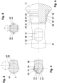
- An den Schaftabschnitt (11) schließt sich ein z.B. 16,4 mm langer Instrumentenhals an, der im Weiteren Hals (20) genannt wird. Der Hals (20) besteht aus einer Halsübergangszone (21), einer Halshauptzylinderzone (31), einer Halskonuszone (35) und einer Halsnebenzylinderzone (36). In der Halsübergangszone (21) wird der Schaftabschnitt (11) zur Halshauptzylinderzone (31) hin verjüngt. Es findet eine Durchmesserreduzierung von z.B. 2,35 mm auf z.B. 1,3 mm statt. Um die durch den Durchmessersprung entstehende Kerbspannung so klein wie möglich zu halten, wird die Halsübergangszone (21) mithilfe der Mattheck'schen Zugdreieckmethode gestaltet, vgl.
Figur 6 . - Die
Figur 6 zeigt die zwischen dem Schaftabschnitt (11) und der Sollbruchzone (40) gelegene Halsübergangszone (21). In der oberen, nicht geschnittenen Hälfte derFigur 6 ist zu erkennen, dass die Halsübergangszone (21) aus einem ersten (23), zweiten (24) und dritten Übergangszonenbereich (25) besteht. Dabei hat der erste, sich an den Schaftabschnitt (11) anschließende Übergangszonenbereich (23), einen sich verjüngenden geraden Konus mit einem Kegelwinkel von 90 Winkelgraden. Der zweite, sich an den ersten Übergangszonenbereich (23) anschließende Übergangszonenbereich (24) hat einen sich verjüngenden geraden weiteren Konus mit einem Kegelwinkel von 45 Winkelgraden. Auch der dritte, sich an den zweiten Übergangszonenbereich (24) anschließende Übergangszonenbereich (25) weist einen sich wiederum verjüngenden geraden Konus mit einem Kegelwinkel von 22,5 Winkelgraden auf. Zwischen den einzelnen Koni ist jeweils ein Übergangsradius von z.B. 0,5 mm vorgesehen. - Die Länge der einzelnen Übergangszonenbereiche (23-25) ergibt sich aus der Konstruktion mittels der - in der Schnittfläche nach
Figur 6 unterschiedlich schraffierten - drei gestrichelt dargestellten Zugdreiecke (26-28). Alle drei Zugdreiecke bilden jeweils ein gleichschenkliges Dreieck. Das erste Zugdreieck (26), es ist rechtwinklig, hat eine Hypotenuse, die sich wie die Kontur einer 45°-Fase von der Kante des Schaftabschnitts (11) auf das Niveau des Außendurchmessers der Halshauptzylinderzone (31) erstreckt. An der mittelliniennahen Hälfte der Hypotenuse des ersten Zugdreiecks (26) schließt sich das spitzwinkelige zweite Zugdreieck (27) mit seiner dem Schaftabschnitt (11) nächstgelegenen Kathete an. Der zwischen der Hypotenuse und einer Kathete eingeschlossene Winkel misst 22,5 Winkelgrade. Das dritte Zugdreieck (28) schmiegt sich mit seiner dem Schaftabschnitt (11) nächstgelegenen Kathete an der mittelliniennahen Hälfte der Hypotenuse des zweiten Zugdreiecks (27) an. Seine andere Kathete befindet sich auf dem Niveau des Außendurchmessers der Halshauptzylinderzone (31). Die beiden halben Hypotenusen der Zugdreiecke (26) und (27) bilden zusammen mit der Hypotenuse des dritten Zugdreiecks (28) die kerbspannungsarme Mattheck'sche Kontur (29). Selbstverständlich kann die Mattheck'sche Kontur (29) durch eine stetige Kurve angenähert werden. - Die zylindrische Halshauptzylinderzone (31) hat eine Länge von z.B. 10,15 mm.
- Im hinteren Bereich der Halshauptzylinderzone (31) befindet sich eine Sollbruchzone (40). Die Mitte der Sollbruchzone (40) liegt z.B. 2,25 mm vor dem Schaftabschnitt (11). Die Sollbruchzone (40) weist z.B. drei bis sechs äquidistant auf dem Umfang der Halshauptzylinderzone (31) verteilt angeordnete Abflachungen (41) auf. Nach den
Figuren 1 und6 werden im Ausführungsbeispiel vier Abflachungen gewählt. Jede Abflachung ist eben ausgebildet und hat die Form eines Rechtecks. Die Rechteckkantenlänge, die parallel zur Mittellinie (3) ausgerichtet ist, hat eine Länge von z.B. 0,5 mm. Die quer zur Mittellinie (3) liegende Rechteckkantenlänge misst z.B. 0,75 mm. Die entlang dem Umfang nebeneinanderliegenden Abflachungen (41) der Sollbruchzone (40) kontaktieren sich gegenseitig nicht, obwohl ihre Flächenschwerpunkte auf einer Ebene liegen, die von der Mittellinie (3) senkrecht geschnitten wird. Die Abflachungen bilden somit ein Vierkantprofil mit abgerundeten Eckbereichen. - An die quer zur Mittellinie (3) liegenden Rechteckkanten schließen sich - in Längsrichtung des Tordierinstruments (1) - jeweils Abflachungsausläufe (42) an, deren konkav gekrümmte Flächen hier Teilflächen eines Zylinders sind, dessen einzelner Durchmesser jeweils z.B. 1 mm misst.
- Der Querschnitt der Sollbruchzone (40) ist um mindestens 18 % kleiner als der reguläre Querschnitt der Halshauptzylinderzone (31).
- Die vorn an die Halshauptzylinderzone (31) anschließende Halskonuszone (35) reduziert ihren Durchmesser zum Arbeitsteil (60) hin auf z.B. 1,1 mm. Die Halskonuszone (35) schließt ausgehend von der Halshauptzylinderzone (31) einen Konuswinkel von 2,86 Winkelgraden ein. Die Halskonuszone (35) hat dabei eine Länge von z.B. 4 mm. An sie schließt sich eine z.B. 1 mm lange Halsnebenzylinderzone (36) an, die sich bis zum Arbeitsteil (60) hin erstreckt.
- Die
Figuren 12-27 zeigen Tordierinstrumente, die im Bereich des nach denFiguren 26 und27 im Handstück (80) steckenden Antriebsschafts (10) verschiedene Sollbruchzonen (40) aufweisen. Vor der jeweiligen Sollbruchzone (40) ist eine zweite, 0,9 mm breite Antriebsabflachung (45) angeordnet, deren Abstand von der Mittellinie (3) dem Mittellinienabstand der ersten Antriebsabflachung (15) entspricht. Die zweite Antriebsabflachung (45) hat die Aufgabe, nach einem Bersten der Sollbruchzone (40) hilfsweise als Antriebsfläche zur Einleitung eines Drehmoments zu dienen. Die zweite Antriebsabflachung (45) endet vorn - wie auch die erste Antriebsabflachung (15) - in einer z.B. planen Stirnanschlagfläche (46). Beide Stirnanschlagflächen (16, 46) sind z.B. 4,8 mm voneinander beabstandet. - In den
Figuren 12 und13 befindet sich unmittelbar hinter der zweiten Antriebsabflachung (45) als Sollbruchzone eine z.B. 0,725 mm tiefe und z.B. 0,9 mm breite Ringnut (51). Die Ringnut (51) hat einen rechteckigen Querschnitt. - Die
Figuren 14 und15 zeigen anstelle der Ringnut (51) eine gleichbreite Rille (52), deren Rillengrundkontur ein Halbkreis ist. Die Rille (52) ist ebenfalls 0,725 mm tief. - Die Sollbruchzone der
Figuren 16 und17 besteht aus einem kurzen Zylinderabschnitt (54) und einer Kerbe (53), deren Kerbflanken mit der Mittellinie (3) jeweils einen Winkel von 45 Winkelgraden einschließen. Der vor der scharfen Kerbe (53) gelegene Zylinderabschnitt (54) hat bei einem Durchmesser von z.B. 1,35 mm eine Länge von 0,53 mm. Der Minimaldurchmesser der Sollbruchzone beträgt im Bereich der 90°-Kerbe 0,9 mm. Dieser Minimaldurchmesser gilt für alle Varianten derFigu-ren 12-27 . - Die
Figuren 18 und19 zeigen zwischen der zweiten (45) und der ersten Antriebsabflachung (15) einen z.B. 3,21 mm langen Kerbkonus (55), dessen Konuswinkel z.B. 24,4 Winkelgrade beträgt. Die schmalste Stelle des Kerbkonus (55) endet in einer planen Teilringfläche unmittelbar vor der zweiten Antriebsabflachung (45). - In den
Figuren 20 und21 bildet die Sollbruchzone eine Umlaufnut (56) mit einem kreisabschnittförmigen Querschnitt. Der Radius der Nutkontur misst z.B. 1,25 mm. Zum Antriebsschaft (10) hin gibt es einen Übergangsradius von z.B. 0,25 mm. - Jede Sollbruchzone der
Figuren 22-25 ist eine umlaufende Nut mit einer Mattheck-Doppel-Kontur (57). Die einfache Mattheck'sche Kontur (29) ist im Zusammenhang mit der Halsübergangszone (21) derFigur 6 beschrieben. Im Fall derFigu-ren 22-25 werden zwei Mattheck'sche Konturen (29) so nebeneinander angeordnet bzw. gespiegelt, dass sich die schmalsten Zugdreiecke beider Konturen an ihren spitzwinkeligen Ecken kontaktieren. - Die Sollbruchzone der
Figuren 24-25 ist mit einer Schutzhülse (59) umgeben, die die umlaufende Nut (57) ausfüllt. Die zylindrische Außenwandung der Schutzhülse (59) hat einen Durchmesser, der z.B. 0,15 mm kleiner ist als der Durchmesser des Antriebsschafts (10). Um die Schutzhülse (59) verliersicher am vorderen Teil des Antriebsschafts (10) zu halten, befindet sich in der zweiten Antriebsabflachung (45) eine kleine Halteausnehmung (58), z.B. in Form einer kurzen Bohrung, in die der Werkstoff der Schutzhülse (59) formschlüssig eingreift. - Bei einem Bruch der Sollbruchzone bleibt auf diese Weise die Schutzhülse (59) am vorderen Teil des Tordierinstruments (1) haften, sodass beim Herausrutschen des Handstücks (80) für den Patienten keine Verletzungsgefahr besteht.
- Die
Figuren 26 und27 zeigen ein Handstück (80), in das das inFigur 20 dargestellte Tordierinstrument verlier- und verdrehsicher eingesteckt ist. In der Schnittdarstellung derFigur 27 ist deutlich zu erkennen, dass sich die Sollbruchzone im mittleren Bereich der Aufnahmebohrung (81) des Handstücks (80) befindet. Auf diese Weise ist sichergestellt, dass bei einem Bruch der Sollbruchzone keine Verletzungsgefahr für den Nutzer des Tordierinstruments (1) ausgeht. - Das Arbeitsteil (60) ist ein Außensechsrundkugelkopf (61). Letzterer ist geeignet, in eine Werkzeugausnehmung (92) eines Einschraubbauteils (90) mit Innensechsrund nach DIN EN ISO 10664 drehmomentübertragend einzugreifen. Der Außensechsrundkugelkopf (61) weist am Umfang sechs Zähne (63) auf, zwischen denen sechs Zahnlücken (66) liegen, vgl. auch
Figur 2 . Die Zahnköpfe (64) der Zähne (63) haben Kopfrundungen, die unmittelbar in die Zahnfußrundungen im Bereich der Zahnlücken (66) übergehen. Das Arbeitsteil (60) überträgt das Drehmoment auf den Innensechsrund (92) des Einschraubbauteils (90) über die Flanken (65) seiner Zähne (63). - Als Arbeitsteilhalbzeug besteht das Arbeitsteil (60) aus einer am vorderen Ende des Halses (20) bzw. der Halsnebenzylinderzone (36) angeformten - auf der Mittellinie (3) gelegenen - Kugel, vgl.
Figur 3 . Die Oberfläche dieser Kugel stellt beim fertigen Produkt die in denFiguren 3-5 gestrichelt eingezeichnete Hüllfläche (62) dar. Sie hat einen Durchmesser von z.B. 1,38 mm - In einem ersten Arbeitsgang wird, gemäß
Figur 3 , am Übergang zur Halsnebenzylinderzone (36) ein Hintergriff (67) erzeugt, der es ermöglicht, die Mittellinie (3) des Tordierinstruments (1) um einen Beugewinkel (7) von bis zu 22 Winkelgraden gegenüber der Mittellinie (99) des Einschraubbauteils (90) zu kippen. Der Hintergriff (67) hat eine Radiuskontur, dessen Radius z.B. 0,55 mm misst. Die Radiuskontur geht tangential in die Halsnebenzylinderzone (36) über. Das Zentrum der Radiuskontur sitzt z.B. 0,4 mm hinter dem auf der Mittellinie (3) liegenden Mittelpunkt der Hüllfläche (62). - In einem weiteren Arbeitsgang wird mithilfe des Formwerkzeugs (100) die Kugel des Arbeitsteilhalbzeugs verzahnt, vgl.
Figur 4 . Mit dem Formwerkzeug (100) wird die Verzahnung, je nach Werkzeugtyp, durch Schleifen oder Fräsen spanabhebend bearbeitet oder in einem Rollvorgang umgeformt. - Das Formwerkzeug (100) hat dazu eine an einem Werkzeugschaft (101) angeformte Profilscheibe (102), vgl.
Figur 7 . Die Profilscheibe (102), die einen Durchmesser von z.B. 4 mm hat, weist ein mittleres Zahnlückenprofil (105) und zwei randseitige Zahnkopfprofile (107) auf. Das Zahnlückenprofil (105) ist Teil einer Torusoberfläche, dessen Durchmesser des Lückenkreises (106) z.B. 0,74 mm beträgt. Die randseitigen Zahnkopfprofile (107) sind jeweils ebenfalls Teil einer Torusoberfläche, deren Durchmesser der Zahnkopfkreise (108) z.B. 0,22 mm misst. Die Mittelpunkte der Zahnkopfkreise (108) liegen zum einen jeweils um z.B. 0,29 mm - parallel zur Mittellinie (3) - beabstandet zum Mittelpunkt des Lückenkreises (106). Zum anderen sind sie zum Mittelpunkt des Lückenkreises (106) um 0,384 mm radial nach außen versetzt angeordnet. Die Zahnkopfkreise (108) kontaktieren jeweils den Lückenkreis (106) in einem Berührpunkt. In den beiden Berührpunkten haben beide Kreise (106, 108) identische Tangenten. - Zum Formen der sechs Zähne (63) und der entsprechenden Zahnlücken (66) wird das Formwerkzeug (100) entlang einer in
Figur 4 dargestellten Zahnlückengrundkontur (71) geführt. Letztere besteht aus einem vorderen, geradlinigen Lückengrundbereich (72), einem mittleren, bogenförmigen Lückengrundbereich (73) und einem hinteren, ebenfalls bogenförmigen Lückengrundbereich (74). Alle drei Lückengrundbereiche (72-74) gehen tangential ineinander über. - Der mittlere Lückengrundbereich (73) ist ein Kreisbogen, der einen Winkel von 40 Winkelgraden und 26 Winkelminuten überdeckt.
- Der Kreisbogen hat einen Radius von z.B. 0,515 mm. Der Mittelpunkt des mittleren Lückengrundbereichs (73) entspricht dem Mittelpunkt der kugelförmigen Hüllfläche (62). Der vorderste Punkt des mittleren Lückengrundbereiches (73) liegt auf einem fiktiven Radiusstrahl (75), der mit der Mittellinie (3) einen Winkel von 50 Winkelgraden einschließt.
- Im vordersten Punkt des mittleren Lückengrundbereiches (73) schließt sich der geradlinige vordere Lückengrundbereich (72) an. Letzterer endet am freien Ende (76) des Arbeitsteils (60). Der geradlinige Lückengrundbereich (72) schließt mit der Mittellinie (3) einen Winkel von 40 Winkelgraden ein.
- Am hinteren Ende des mittleren Lückengrundbereiches (73) beginnt der hintere Lückengrundbereich (74). Er hat einen Radius von z.B. 2,175 mm. Der hintere Lückengrundbereich (74) läuft im Hintergriff (67) des Arbeitsteils (60) aus.
- Nach jedem Abfahren der Zahnlückengrundkontur (71) wird das Arbeitsteilhalbzeug für den nächsten Formvorgang um 60 Winkelgrade weitergeschwenkt. Auf diese Weise entsteht eine Verzahnung, wie sie in
Figur 5 als Querschnitt durch den Mittelpunkt der Hüllfläche (62) und inFigur 2 in einer perspektivischen Ansicht dargestellt ist. NachFigur 2 ist die Spitze (76) des Arbeitsteils (60) ein Kopfstern (77), dessen kleinster Durchmesser z.B. 0,18 mm misst. Die Wölbung des Kopfsterns (77) entspricht der Wölbung der Hüllfläche (62). - Alle Maße beziehen sich auf einen Innensechsrund für Schrauben nach DIN EN ISO 10664, Typ Nr. 5.
- Das Einschraubbauteil (90) ist abhängig vom Abutmenttyp eine Schraube, ein Gewindebolzen oder dergleichen. Der Kopf der Schraube oder mindestens eines der Enden des Gewindebolzens hat eine Werkzeugausnehmung (92), die ein Innensechsrund nach DIN EN ISO 10664 darstellt, vgl.
Figuren 8-11 . Nach diesen Figuren weist die Werkzeugausnehmung (92) im Bereich ihrer Öffnung (93) eine 30°-Fase (94) auf, deren Breite kleiner ist als die halbe Tiefe (98) des Nutzbereichs der Werkzeugausnehmung (92). Die Breite der 30°-Fase (94) beträgt nach denFiguren 9 und11 z.B. 0,36 mm. - Die Werkzeugausnehmung (92) hat einen Boden (95), der die Form eines geraden Kegels aufweist, dessen Kegelwinkel z.B. 118 Winkelgrade misst und dessen Spitze (76) weiter von der Öffnung (93) der Werkzeugausnehmung (92) entfernt liegt als die Kegelgrundlinie. Auf diesem Boden (95) stützt sich das Tordierinstrument (1) bei jedem Ein- oder Ausschraubvorgang des Einschraubbauteils (90) ab, um eine sichere Anlage des Arbeitsteils (60) in der Werkzeugausnehmung (92) zu gewährleisten.
- Alternativ kann in der Werkzeugausnehmung (92) auch ein Boden (96) vorgesehen werden, dessen Bodenfläche sphärisch gekrümmt ist, vgl. gestrichelt gezeichneter Bogen in den
Figuren 9 und10 . Die Krümmung des Bodens (96) hat einen Radius von z.B. 0,7 mm. Der Mittelpunkt der Krümmung liegt z.B. 0,265 mm unterhalb der planen, die Werkzeugausnehmung (92) umgebenden Stirnfläche des Einschraubbauteils (90). Ggf. kann der Boden auch eine anders gekrümmte Rotationsfläche oder sogar eine tiefergesetzte Planfläche sein. - Zum Einschrauben des Einschraubbauteils (90) - in den in den Figuren nicht dargestellten Implantatkörper - wird das Tordierinstrument (1) mit seinem Arbeitsteil (60) in die Werkzeugausnehmung (92) des Einschraubbauteils (90) eingeführt. Dabei greifen zum einem die Zähne (63) des Arbeitsteils (60) in die Zahnlücken der Werkzeugausnehmung (92) mit minimalem Spiel ein. Zum anderen legt sich die Spitze (76) bzw. der Kopfstern (77) des Arbeitsteils (60) am Boden (96) des Einschraubbauteils (90) an, vgl.
Figuren 8-11 . - In den
Figur 8 und10 ist das Arbeitsteil (60) des Tordierinstruments (1) im Bereich der Zahnköpfe (64) der Außensechsrundzähne (63) geschnitten, während in denFiguren 9 und11 das Einschraubbauteil (90) um idealerweise z.B. 30 Winkelgrade um seine Mittellinie (99) geschwenkt dargestellt ist. Demnach ist auch das Tordierinstrument (1) ebenfalls idealerweise um z.B. 30 Winkelgrade um seine Mittellinie (3) geschwenkt worden. - Der mit zunehmendem Beugewinkel (7) größer werdende Kardanfehler bewirkt zumindest theoretisch einen Versatz und eine Winkeländerung der Mittellinie (99) des Tordierinstruments (1) zwischen den
Figuren 8 und 9 sowie 10 und 11. Dies wird hier vernachlässigt. - Gegen Ende des Einschraubvorgangs nimmt das Anzugsdrehmoment sprunghaft zu. Um ein Erreichen des maximalen Anzugsdrehmoments am Handstück (80) des Tordierinstruments (1) für den Nutzer haptisch erfahrbar zu machen, tordiert sich der Hals (20) des Tordierinstruments (1) nach
Figur 1 um 10-12 Winkelgrade, ohne dass sich in der Sollbruchzone (40) eine messbare plastische Verformung ergibt. -
- 1
- Tordierinstrument, Schraubendrehinstrument
- 3
- Mittellinie
- 7
- Beugewinkel, Winkel zwischen (3) und (99)
- 10
- Antriebsschaft
- 11
- Schaftabschnitt, zylindrisch
- 15
- Antriebsabflachung, erste
- 16
- Stirnanschlagfläche
- 17
- Rille, Nut
- 20
- Hals, Instrumentenhals
- 21
- Halsübergangszone
- 23
- erster Übergangszonenbereich
- 24
- zweiter Übergangszonenbereich
- 25
- dritter Übergangszonenbereich
- 26
- erstes Zugdreieck, rechtwinkelig
- 27
- zweites Zugdreieck
- 28
- drittes Zugdreieck
- 29
- Mattheck'sche Kontur
- 31
- Halszylinderzone, Halshauptzylinderzone
- 35
- Halskonuszone, Halsabschnitt
- 36
- Halszylinderzone, Halsnebenzylinderzone, Halsabschnitt
- 40
- Sollbruchzone
- 41
- Abflachungen, vier, plan
- 42
- Abflachungsausläufe
- 45
- Antriebsabflachung, zweite
- 46
- Stirnanschlagfläche
- 51
- Ringnut
- 52
- Rille
- 53
- Kerbe, 90°-Kerbe
- 54
- Zylinderabschnitt
- 55
- Kerbkonus, Konus
- 56
- Umlaufnut
- 57
- Mattheck-Doppel-Kontur; Nut, umlaufend
- 58
- Halteausnehmung
- 59
- Schutzhülse
- 60
- Arbeitsteil
- 61
- Kugelkopf, Außensechsrundkugelkopf
- 62
- Hüllfläche, kugelförmig, Kugel
- 63
- Zähne, Außensechsrundzähne
- 64
- Zahnköpfe
- 65
- Flanken, Zahnflanken
- 66
- Zahnlücken
- 67
- Hintergriff
- 71
- Zahnlückengrundkontur
- 72
- vorderer Lückengrundbereich, geradlinig
- 73
- mittlerer Lückengrundbereich, bogenförmig
- 74
- hinterer Lückengrundbereich, bogenförmig
- 75
- Radiusstrahl von (60), fiktiv
- 76
- freies Ende, Spitze
- 77
- Kopfstern
- 80
- Handstück, Griff, Betätigungselement
- 81
- Aufnahmebohrung
- 90
- Einschraubbauteil, Schraube
- 91
- Kopf, Innensechsrundkopf
- 92
- Werkzeugausnehmung, Innensechsrund, Torx ®
- 93
- Öffnung
- 94
- Fase, 30°-Fase
- 95
- Boden von (92), kegelmantelförmig
- 96
- Boden, sphärisch gekrümmt
- 98
- Tiefe, Eindringtiefe von (92)
- 99
- Mittellinie von (90)
- 100
- Formwerkzeug
- 101
- Werkzeugschaft
- 102
- Profilscheibe
- 105
- Zahnlückenprofil, Mitte
- 106
- Lückenkreis, Kreis
- 107
- Zahnkopfprofil, randseitig
- 108
- Zahnkopfkreise, Kreise
Claims (8)
- Tordierinstrument für ein Einschraubbauteil (90) mit einer Werkzeugausnehmung (92), das einen Antriebsschaft (10), einen Hals (20) und ein Arbeitsteil (60) umfasst,- wobei das Arbeitsteil (60) - als ein sechs Zähne (63) aufweisender Kugelkopf (61) - eine kugelförmige Hüllfläche (62) hat, die mindestens sowohl vom freien Ende (76) als auch von Teilbereichen der zähneeigenen Zahnköpfe (64) des Arbeitsteils (60) kontaktiert wird,- wobei zwischen den Zähnen (63) sechs Zahnlücken (66) liegen,- wobei der Hals (20) oder der Antriebsschaft (10) eine Sollbruchzone (40) aufweist,- wobei der Hals (20) aus einer Halsübergangszone (21), einer Halshauptzylinderzone (31), einer Halskonuszone (35) und einer Halsnebenzylinderzone (36) besteht und- wobei der Kugelkopf (61) am Übergang des Kugelkopfs (61) zur Halsnebenzylinderzone (36) einen Hintergriff (67) hat, dessen Radiuskontur tangential in die Halsnebenzylinderzone (36) übergeht.
- Tordierinstrument gemäß Anspruch 1, dadurch gekennzeichnet, dass der Antriebsschaft (10) nach DIN EN ISO 1797 zum Typ 1 zählt, der an seinem freien Ende mit einer Antriebsabflachung (15) und einer Rille (17) ausgestattet ist.
- Tordierinstrument gemäß Anspruch 1, dadurch gekennzeichnet, dass die Halsübergangszone (21) einen ersten (23), zweiten (24) und dritten Übergangszonenbereich (25) umfasst, wobei der erste sich an den Antriebsschaft (10) anschließende Übergangszonenbereich (23), ein sich verjüngender gerader Konus mit einem Kegelwinkel von 90 Winkelgraden ist, wobei der zweite sich an den ersten Übergangszonenbereich (23) anschließende Übergangszonenbereich (24), ein sich verjüngender gerader Konus mit einem Kegelwinkel von 45 Winkelgraden ist und wobei der dritte sich an den zweiten Übergangszonenbereich (24) anschließende Übergangszonenbereich (25), ein sich verjüngender gerader Konus mit einem Kegelwinkel von 22,5 Winkelgraden ist.
- Tordierinstrument gemäß Anspruch 1, dadurch gekennzeichnet, dass die an den Antriebsschaft (10) anschließende Halszylinderzone (31) eine Länge hat, die mindestens dem 6,6-fachen Durchmesser der Halszylinderzone (31) entspricht und dass der zwischen der Halszylinderzone (31) und dem Arbeitsteil (60) gelegene Halsabschnitt eine Länge hat, die mindestens das 5,5-fache des kleinsten Durchmessers dieses Halsabschnittes aufweist.
- Tordierinstrument gemäß Anspruch 1, dadurch gekennzeichnet, dass die Sollbruchzone (40) im hinteren Bereich der an die Halsübergangszone (21) anschließenden Halszylinderzone (31) angeordnet ist.
- Tordierinstrument gemäß Anspruch 1, dadurch gekennzeichnet, dass die Sollbruchzone (40) vier äquidistant auf dem Umfang der an die Halsübergangszone (21) anschließenden Halszylinderzone (31) verteilt angeordnete Abflachungen (41) aufweist.
- Tordierinstrument gemäß Anspruch 6, dadurch gekennzeichnet, dass sich die nebeneinanderliegenden Abflachungen (41) der Sollbruchzone (40) gegenseitig nicht kontaktieren.
- Tordierinstrument gemäß Anspruch 1, dadurch gekennzeichnet, dass der Kugelkopf (61) ein Außensechsrundkugelkopf ist.
Applications Claiming Priority (2)
| Application Number | Priority Date | Filing Date | Title |
|---|---|---|---|
| DE102020003492.6A DE102020003492A1 (de) | 2020-06-11 | 2020-06-11 | Tordierinstrument |
| PCT/DE2021/000105 WO2021249587A1 (de) | 2020-06-11 | 2021-06-03 | Tordierinstrument |
Publications (2)
| Publication Number | Publication Date |
|---|---|
| EP4164543A1 EP4164543A1 (de) | 2023-04-19 |
| EP4164543B1 true EP4164543B1 (de) | 2025-04-09 |
Family
ID=77103742
Family Applications (1)
| Application Number | Title | Priority Date | Filing Date |
|---|---|---|---|
| EP21746632.5A Active EP4164543B1 (de) | 2020-06-11 | 2021-06-03 | Tordierinstrument |
Country Status (5)
| Country | Link |
|---|---|
| US (1) | US20230240815A1 (de) |
| EP (1) | EP4164543B1 (de) |
| KR (1) | KR20230077714A (de) |
| DE (1) | DE102020003492A1 (de) |
| WO (1) | WO2021249587A1 (de) |
Family Cites Families (8)
| Publication number | Priority date | Publication date | Assignee | Title |
|---|---|---|---|---|
| CH282211A (de) * | 1950-10-13 | 1952-04-15 | Hugo Dr Ackermann | Bohrer zur konischen Präparation eines Teils eines Zahnwurzelkanals. |
| US5019080A (en) * | 1990-02-13 | 1991-05-28 | Trextron Inc. | Drive system for prosthetic fasteners |
| US5251521A (en) | 1992-01-31 | 1993-10-12 | Bondhus Corporation | TORX-compatible elliptical driver |
| DE9303828U1 (de) | 1993-03-11 | 1993-06-24 | AAP GmbH & Co. Betriebs KG, 1000 Berlin | Schraubendreher |
| WO1998038010A1 (en) * | 1997-02-28 | 1998-09-03 | Sofamor Danek Properties, Inc. | Recessed drive fastener and cooperable driving tool |
| BR102012029369A2 (pt) | 2012-11-19 | 2014-09-23 | Esteban Xam-Mar Mangrane | Aperfeiçoamentos introduzidos em conjunto pilar dinâmico |
| WO2017070335A1 (en) | 2015-10-20 | 2017-04-27 | Implant Direct Sybron International Llc | Screw and driver tool for dental procedures |
| ES2677998B1 (es) * | 2017-02-07 | 2019-05-20 | Vogul S L U | Destornillador para implantes dentales |
-
2020
- 2020-06-11 DE DE102020003492.6A patent/DE102020003492A1/de active Pending
-
2021
- 2021-06-03 EP EP21746632.5A patent/EP4164543B1/de active Active
- 2021-06-03 US US18/009,464 patent/US20230240815A1/en not_active Abandoned
- 2021-06-03 WO PCT/DE2021/000105 patent/WO2021249587A1/de not_active Ceased
- 2021-06-03 KR KR1020237001235A patent/KR20230077714A/ko active Pending
Also Published As
| Publication number | Publication date |
|---|---|
| WO2021249587A1 (de) | 2021-12-16 |
| KR20230077714A (ko) | 2023-06-01 |
| EP4164543A1 (de) | 2023-04-19 |
| US20230240815A1 (en) | 2023-08-03 |
| DE102020003492A1 (de) | 2021-12-16 |
Similar Documents
| Publication | Publication Date | Title |
|---|---|---|
| EP3487442B1 (de) | Suprastrukturträger mit besonderer implantatpfostengeometrie | |
| DE69431401T2 (de) | Streckmechanismus für externe fixiervorrichtung | |
| EP1843717B1 (de) | Dentalimplantat | |
| EP1972297B1 (de) | Kombination eines Abutments und einer zweiteilige Schraube | |
| EP0988833B1 (de) | Osteosyntheseplatte mit mehreren Knochenschrauben | |
| EP3223741A1 (de) | Enossales einzelzahnimplantat | |
| DE102011010897B4 (de) | Dentalinstrument sowie Verfahren zu dessen Herstellung | |
| DE102009015358B4 (de) | Schraube, Schraubwerkzeug und deren Verwendung zur Herstellung von Zahnprothesen | |
| EP3487441B1 (de) | Dentaler suprastrukturträger mit besonderer innen- und aussengeometrie | |
| EP4054477B1 (de) | Systemmontageschnittstelle | |
| EP3565976B1 (de) | Vorrichtung zur drehmomentbegrenzung mit drei stegen | |
| DE3309884C2 (de) | ||
| EP3302343B1 (de) | Zahnersatzsystem | |
| DE19644177B4 (de) | Steckschlüssel | |
| DE102007041574A1 (de) | Schraubendreherbit mit beidendseitigem Schraubeingriffsprofil | |
| DE19625416A1 (de) | Anordnung aus einem Schraubendreher und einer entsprechenden Schraube | |
| EP4164543A1 (de) | Tordierinstrument | |
| WO1994015110A1 (de) | Kupplung | |
| DE102019116238A1 (de) | Drehmomentbegrenzungseinrichtung und Verfahren zu dessen Kalibrierung | |
| EP2945562B1 (de) | Schaft eines dentalwerkzeugs | |
| EP4193068B1 (de) | Befestigungselement und einstellsystem umfassend ein befestigungselement | |
| EP2627481B1 (de) | Drehmomentübertragungseinrichtung insbesondere in form eines spannfutters für bits | |
| DE202009003923U1 (de) | Medizinische Schraube | |
| DE19511478A1 (de) | Konterhebel für eine Mutter, insbesondere für eine Vorrichtung zum Richten von Wirbelsäulen | |
| EP4077954A1 (de) | Schraubenantrieb |
Legal Events
| Date | Code | Title | Description |
|---|---|---|---|
| STAA | Information on the status of an ep patent application or granted ep patent |
Free format text: STATUS: UNKNOWN |
|
| STAA | Information on the status of an ep patent application or granted ep patent |
Free format text: STATUS: THE INTERNATIONAL PUBLICATION HAS BEEN MADE |
|
| PUAI | Public reference made under article 153(3) epc to a published international application that has entered the european phase |
Free format text: ORIGINAL CODE: 0009012 |
|
| STAA | Information on the status of an ep patent application or granted ep patent |
Free format text: STATUS: REQUEST FOR EXAMINATION WAS MADE |
|
| 17P | Request for examination filed |
Effective date: 20221209 |
|
| AK | Designated contracting states |
Kind code of ref document: A1 Designated state(s): AL AT BE BG CH CY CZ DE DK EE ES FI FR GB GR HR HU IE IS IT LI LT LU LV MC MK MT NL NO PL PT RO RS SE SI SK SM TR |
|
| DAV | Request for validation of the european patent (deleted) | ||
| DAX | Request for extension of the european patent (deleted) | ||
| GRAP | Despatch of communication of intention to grant a patent |
Free format text: ORIGINAL CODE: EPIDOSNIGR1 |
|
| STAA | Information on the status of an ep patent application or granted ep patent |
Free format text: STATUS: GRANT OF PATENT IS INTENDED |
|
| RIC1 | Information provided on ipc code assigned before grant |
Ipc: B25B 15/00 20060101ALI20231207BHEP Ipc: B25B 13/48 20060101ALI20231207BHEP Ipc: A61C 8/00 20060101AFI20231207BHEP |
|
| INTG | Intention to grant announced |
Effective date: 20240105 |
|
| GRAA | (expected) grant |
Free format text: ORIGINAL CODE: 0009210 |
|
| GRAS | Grant fee paid |
Free format text: ORIGINAL CODE: EPIDOSNIGR3 |
|
| STAA | Information on the status of an ep patent application or granted ep patent |
Free format text: STATUS: THE PATENT HAS BEEN GRANTED |
|
| AK | Designated contracting states |
Kind code of ref document: B1 Designated state(s): AL AT BE BG CH CY CZ DE DK EE ES FI FR GB GR HR HU IE IS IT LI LT LU LV MC MK MT NL NO PL PT RO RS SE SI SK SM TR |
|
| REG | Reference to a national code |
Ref country code: GB Ref legal event code: FG4D Free format text: NOT ENGLISH |
|
| REG | Reference to a national code |
Ref country code: CH Ref legal event code: EP |
|
| REG | Reference to a national code |
Ref country code: DE Ref legal event code: R096 Ref document number: 502021007182 Country of ref document: DE |
|
| REG | Reference to a national code |
Ref country code: IE Ref legal event code: FG4D Free format text: LANGUAGE OF EP DOCUMENT: GERMAN |
|
| PGFP | Annual fee paid to national office [announced via postgrant information from national office to epo] |
Ref country code: AT Payment date: 20250721 Year of fee payment: 5 |
|
| REG | Reference to a national code |
Ref country code: NL Ref legal event code: MP Effective date: 20250409 |
|
| PG25 | Lapsed in a contracting state [announced via postgrant information from national office to epo] |
Ref country code: NL Free format text: LAPSE BECAUSE OF FAILURE TO SUBMIT A TRANSLATION OF THE DESCRIPTION OR TO PAY THE FEE WITHIN THE PRESCRIBED TIME-LIMIT Effective date: 20250409 |
|
| PG25 | Lapsed in a contracting state [announced via postgrant information from national office to epo] |
Ref country code: PT Free format text: LAPSE BECAUSE OF FAILURE TO SUBMIT A TRANSLATION OF THE DESCRIPTION OR TO PAY THE FEE WITHIN THE PRESCRIBED TIME-LIMIT Effective date: 20250811 Ref country code: FI Free format text: LAPSE BECAUSE OF FAILURE TO SUBMIT A TRANSLATION OF THE DESCRIPTION OR TO PAY THE FEE WITHIN THE PRESCRIBED TIME-LIMIT Effective date: 20250409 Ref country code: ES Free format text: LAPSE BECAUSE OF FAILURE TO SUBMIT A TRANSLATION OF THE DESCRIPTION OR TO PAY THE FEE WITHIN THE PRESCRIBED TIME-LIMIT Effective date: 20250409 |
|
| PGFP | Annual fee paid to national office [announced via postgrant information from national office to epo] |
Ref country code: DE Payment date: 20250807 Year of fee payment: 5 |
|
| REG | Reference to a national code |
Ref country code: LT Ref legal event code: MG9D |
|
| PG25 | Lapsed in a contracting state [announced via postgrant information from national office to epo] |
Ref country code: GR Free format text: LAPSE BECAUSE OF FAILURE TO SUBMIT A TRANSLATION OF THE DESCRIPTION OR TO PAY THE FEE WITHIN THE PRESCRIBED TIME-LIMIT Effective date: 20250710 Ref country code: NO Free format text: LAPSE BECAUSE OF FAILURE TO SUBMIT A TRANSLATION OF THE DESCRIPTION OR TO PAY THE FEE WITHIN THE PRESCRIBED TIME-LIMIT Effective date: 20250709 |
|
| PG25 | Lapsed in a contracting state [announced via postgrant information from national office to epo] |
Ref country code: PL Free format text: LAPSE BECAUSE OF FAILURE TO SUBMIT A TRANSLATION OF THE DESCRIPTION OR TO PAY THE FEE WITHIN THE PRESCRIBED TIME-LIMIT Effective date: 20250409 |
|
| PG25 | Lapsed in a contracting state [announced via postgrant information from national office to epo] |
Ref country code: BG Free format text: LAPSE BECAUSE OF FAILURE TO SUBMIT A TRANSLATION OF THE DESCRIPTION OR TO PAY THE FEE WITHIN THE PRESCRIBED TIME-LIMIT Effective date: 20250409 |
|
| PGFP | Annual fee paid to national office [announced via postgrant information from national office to epo] |
Ref country code: GB Payment date: 20250829 Year of fee payment: 5 |
|
| PG25 | Lapsed in a contracting state [announced via postgrant information from national office to epo] |
Ref country code: HR Free format text: LAPSE BECAUSE OF FAILURE TO SUBMIT A TRANSLATION OF THE DESCRIPTION OR TO PAY THE FEE WITHIN THE PRESCRIBED TIME-LIMIT Effective date: 20250409 |
|
| PGFP | Annual fee paid to national office [announced via postgrant information from national office to epo] |
Ref country code: FR Payment date: 20250807 Year of fee payment: 5 |
|
| PG25 | Lapsed in a contracting state [announced via postgrant information from national office to epo] |
Ref country code: RS Free format text: LAPSE BECAUSE OF FAILURE TO SUBMIT A TRANSLATION OF THE DESCRIPTION OR TO PAY THE FEE WITHIN THE PRESCRIBED TIME-LIMIT Effective date: 20250709 |
|
| PG25 | Lapsed in a contracting state [announced via postgrant information from national office to epo] |
Ref country code: IS Free format text: LAPSE BECAUSE OF FAILURE TO SUBMIT A TRANSLATION OF THE DESCRIPTION OR TO PAY THE FEE WITHIN THE PRESCRIBED TIME-LIMIT Effective date: 20250809 |
|
| PG25 | Lapsed in a contracting state [announced via postgrant information from national office to epo] |
Ref country code: LV Free format text: LAPSE BECAUSE OF FAILURE TO SUBMIT A TRANSLATION OF THE DESCRIPTION OR TO PAY THE FEE WITHIN THE PRESCRIBED TIME-LIMIT Effective date: 20250409 |
|
| REG | Reference to a national code |
Ref country code: DE Ref legal event code: R097 Ref document number: 502021007182 Country of ref document: DE |
|
| PG25 | Lapsed in a contracting state [announced via postgrant information from national office to epo] |
Ref country code: SM Free format text: LAPSE BECAUSE OF FAILURE TO SUBMIT A TRANSLATION OF THE DESCRIPTION OR TO PAY THE FEE WITHIN THE PRESCRIBED TIME-LIMIT Effective date: 20250409 Ref country code: DK Free format text: LAPSE BECAUSE OF FAILURE TO SUBMIT A TRANSLATION OF THE DESCRIPTION OR TO PAY THE FEE WITHIN THE PRESCRIBED TIME-LIMIT Effective date: 20250409 |
|
| PG25 | Lapsed in a contracting state [announced via postgrant information from national office to epo] |
Ref country code: CZ Free format text: LAPSE BECAUSE OF FAILURE TO SUBMIT A TRANSLATION OF THE DESCRIPTION OR TO PAY THE FEE WITHIN THE PRESCRIBED TIME-LIMIT Effective date: 20250409 |
|
| PG25 | Lapsed in a contracting state [announced via postgrant information from national office to epo] |
Ref country code: EE Free format text: LAPSE BECAUSE OF FAILURE TO SUBMIT A TRANSLATION OF THE DESCRIPTION OR TO PAY THE FEE WITHIN THE PRESCRIBED TIME-LIMIT Effective date: 20250409 |
|
| PG25 | Lapsed in a contracting state [announced via postgrant information from national office to epo] |
Ref country code: SK Free format text: LAPSE BECAUSE OF FAILURE TO SUBMIT A TRANSLATION OF THE DESCRIPTION OR TO PAY THE FEE WITHIN THE PRESCRIBED TIME-LIMIT Effective date: 20250409 |
|
| REG | Reference to a national code |
Ref country code: CH Ref legal event code: H13 Free format text: ST27 STATUS EVENT CODE: U-0-0-H10-H13 (AS PROVIDED BY THE NATIONAL OFFICE) Effective date: 20260127 |
|
| PG25 | Lapsed in a contracting state [announced via postgrant information from national office to epo] |
Ref country code: IT Free format text: LAPSE BECAUSE OF FAILURE TO SUBMIT A TRANSLATION OF THE DESCRIPTION OR TO PAY THE FEE WITHIN THE PRESCRIBED TIME-LIMIT Effective date: 20250409 |
|
| PG25 | Lapsed in a contracting state [announced via postgrant information from national office to epo] |
Ref country code: MC Free format text: LAPSE BECAUSE OF FAILURE TO SUBMIT A TRANSLATION OF THE DESCRIPTION OR TO PAY THE FEE WITHIN THE PRESCRIBED TIME-LIMIT Effective date: 20250409 |
|
| PG25 | Lapsed in a contracting state [announced via postgrant information from national office to epo] |
Ref country code: RO Free format text: LAPSE BECAUSE OF FAILURE TO SUBMIT A TRANSLATION OF THE DESCRIPTION OR TO PAY THE FEE WITHIN THE PRESCRIBED TIME-LIMIT Effective date: 20250409 |
|
| PLBE | No opposition filed within time limit |
Free format text: ORIGINAL CODE: 0009261 |
|
| STAA | Information on the status of an ep patent application or granted ep patent |
Free format text: STATUS: NO OPPOSITION FILED WITHIN TIME LIMIT |
|
| PG25 | Lapsed in a contracting state [announced via postgrant information from national office to epo] |
Ref country code: LU Free format text: LAPSE BECAUSE OF NON-PAYMENT OF DUE FEES Effective date: 20250603 |
|
| REG | Reference to a national code |
Ref country code: CH Ref legal event code: L10 Free format text: ST27 STATUS EVENT CODE: U-0-0-L10-L00 (AS PROVIDED BY THE NATIONAL OFFICE) Effective date: 20260218 |
|
| REG | Reference to a national code |
Ref country code: BE Ref legal event code: MM Effective date: 20250630 |
|
| 26N | No opposition filed |
Effective date: 20260112 |
|
| PG25 | Lapsed in a contracting state [announced via postgrant information from national office to epo] |
Ref country code: IE Free format text: LAPSE BECAUSE OF NON-PAYMENT OF DUE FEES Effective date: 20250603 |
|
| PG25 | Lapsed in a contracting state [announced via postgrant information from national office to epo] |
Ref country code: BE Free format text: LAPSE BECAUSE OF NON-PAYMENT OF DUE FEES Effective date: 20250630 |
|
| PG25 | Lapsed in a contracting state [announced via postgrant information from national office to epo] |
Ref country code: CH Free format text: LAPSE BECAUSE OF NON-PAYMENT OF DUE FEES Effective date: 20250630 |