EP4164040B1 - Batteriemodul, batteriepack und fahrzeug damit - Google Patents
Batteriemodul, batteriepack und fahrzeug damit Download PDFInfo
- Publication number
- EP4164040B1 EP4164040B1 EP21869624.3A EP21869624A EP4164040B1 EP 4164040 B1 EP4164040 B1 EP 4164040B1 EP 21869624 A EP21869624 A EP 21869624A EP 4164040 B1 EP4164040 B1 EP 4164040B1
- Authority
- EP
- European Patent Office
- Prior art keywords
- battery
- battery module
- hole
- connection
- present disclosure
- Prior art date
- Legal status (The legal status is an assumption and is not a legal conclusion. Google has not performed a legal analysis and makes no representation as to the accuracy of the status listed.)
- Active
Links
Images


Classifications
-
- H—ELECTRICITY
- H01—ELECTRIC ELEMENTS
- H01M—PROCESSES OR MEANS, e.g. BATTERIES, FOR THE DIRECT CONVERSION OF CHEMICAL ENERGY INTO ELECTRICAL ENERGY
- H01M50/00—Constructional details or processes of manufacture of the non-active parts of electrochemical cells other than fuel cells, e.g. hybrid cells
- H01M50/30—Arrangements for facilitating escape of gases
- H01M50/342—Non-re-sealable arrangements
- H01M50/3425—Non-re-sealable arrangements in the form of rupturable membranes or weakened parts, e.g. pierced with the aid of a sharp member
-
- H—ELECTRICITY
- H01—ELECTRIC ELEMENTS
- H01M—PROCESSES OR MEANS, e.g. BATTERIES, FOR THE DIRECT CONVERSION OF CHEMICAL ENERGY INTO ELECTRICAL ENERGY
- H01M50/00—Constructional details or processes of manufacture of the non-active parts of electrochemical cells other than fuel cells, e.g. hybrid cells
- H01M50/20—Mountings; Secondary casings or frames; Racks, modules or packs; Suspension devices; Shock absorbers; Transport or carrying devices; Holders
- H01M50/204—Racks, modules or packs for multiple batteries or multiple cells
- H01M50/207—Racks, modules or packs for multiple batteries or multiple cells characterised by their shape
- H01M50/213—Racks, modules or packs for multiple batteries or multiple cells characterised by their shape adapted for cells having curved cross-section, e.g. round or elliptic
-
- H—ELECTRICITY
- H01—ELECTRIC ELEMENTS
- H01M—PROCESSES OR MEANS, e.g. BATTERIES, FOR THE DIRECT CONVERSION OF CHEMICAL ENERGY INTO ELECTRICAL ENERGY
- H01M50/00—Constructional details or processes of manufacture of the non-active parts of electrochemical cells other than fuel cells, e.g. hybrid cells
- H01M50/20—Mountings; Secondary casings or frames; Racks, modules or packs; Suspension devices; Shock absorbers; Transport or carrying devices; Holders
- H01M50/271—Lids or covers for the racks or secondary casings
-
- H—ELECTRICITY
- H01—ELECTRIC ELEMENTS
- H01M—PROCESSES OR MEANS, e.g. BATTERIES, FOR THE DIRECT CONVERSION OF CHEMICAL ENERGY INTO ELECTRICAL ENERGY
- H01M50/00—Constructional details or processes of manufacture of the non-active parts of electrochemical cells other than fuel cells, e.g. hybrid cells
- H01M50/30—Arrangements for facilitating escape of gases
- H01M50/342—Non-re-sealable arrangements
-
- H—ELECTRICITY
- H01—ELECTRIC ELEMENTS
- H01M—PROCESSES OR MEANS, e.g. BATTERIES, FOR THE DIRECT CONVERSION OF CHEMICAL ENERGY INTO ELECTRICAL ENERGY
- H01M50/00—Constructional details or processes of manufacture of the non-active parts of electrochemical cells other than fuel cells, e.g. hybrid cells
- H01M50/30—Arrangements for facilitating escape of gases
- H01M50/394—Gas-pervious parts or elements
-
- H—ELECTRICITY
- H01—ELECTRIC ELEMENTS
- H01M—PROCESSES OR MEANS, e.g. BATTERIES, FOR THE DIRECT CONVERSION OF CHEMICAL ENERGY INTO ELECTRICAL ENERGY
- H01M50/00—Constructional details or processes of manufacture of the non-active parts of electrochemical cells other than fuel cells, e.g. hybrid cells
- H01M50/50—Current conducting connections for cells or batteries
- H01M50/502—Interconnectors for connecting terminals of adjacent batteries; Interconnectors for connecting cells outside a battery casing
- H01M50/503—Interconnectors for connecting terminals of adjacent batteries; Interconnectors for connecting cells outside a battery casing characterised by the shape of the interconnectors
-
- H—ELECTRICITY
- H01—ELECTRIC ELEMENTS
- H01M—PROCESSES OR MEANS, e.g. BATTERIES, FOR THE DIRECT CONVERSION OF CHEMICAL ENERGY INTO ELECTRICAL ENERGY
- H01M50/00—Constructional details or processes of manufacture of the non-active parts of electrochemical cells other than fuel cells, e.g. hybrid cells
- H01M50/50—Current conducting connections for cells or batteries
- H01M50/502—Interconnectors for connecting terminals of adjacent batteries; Interconnectors for connecting cells outside a battery casing
- H01M50/505—Interconnectors for connecting terminals of adjacent batteries; Interconnectors for connecting cells outside a battery casing comprising a single busbar
-
- H—ELECTRICITY
- H01—ELECTRIC ELEMENTS
- H01M—PROCESSES OR MEANS, e.g. BATTERIES, FOR THE DIRECT CONVERSION OF CHEMICAL ENERGY INTO ELECTRICAL ENERGY
- H01M2200/00—Safety devices for primary or secondary batteries
-
- H—ELECTRICITY
- H01—ELECTRIC ELEMENTS
- H01M—PROCESSES OR MEANS, e.g. BATTERIES, FOR THE DIRECT CONVERSION OF CHEMICAL ENERGY INTO ELECTRICAL ENERGY
- H01M2220/00—Batteries for particular applications
- H01M2220/20—Batteries in motive systems, e.g. vehicle, ship, plane
-
- Y—GENERAL TAGGING OF NEW TECHNOLOGICAL DEVELOPMENTS; GENERAL TAGGING OF CROSS-SECTIONAL TECHNOLOGIES SPANNING OVER SEVERAL SECTIONS OF THE IPC; TECHNICAL SUBJECTS COVERED BY FORMER USPC CROSS-REFERENCE ART COLLECTIONS [XRACs] AND DIGESTS
- Y02—TECHNOLOGIES OR APPLICATIONS FOR MITIGATION OR ADAPTATION AGAINST CLIMATE CHANGE
- Y02E—REDUCTION OF GREENHOUSE GAS [GHG] EMISSIONS, RELATED TO ENERGY GENERATION, TRANSMISSION OR DISTRIBUTION
- Y02E60/00—Enabling technologies; Technologies with a potential or indirect contribution to GHG emissions mitigation
- Y02E60/10—Energy storage using batteries
Definitions
- the present disclosure relates to a battery module, a battery pack and a vehicle including the same, and more particularly, to a battery module with improved stability against fire or explosion, a battery pack and a vehicle including the same.
- Secondary batteries commercialized at the present include nickel cadmium batteries, nickel hydrogen batteries, nickel zinc batteries, and lithium secondary batteries.
- lithium secondary batteries are in the spotlight due to advantages such as free charging and discharging by little memory effect compared to nickel-based secondary batteries, and very low self-discharge rate and high energy density.
- the lithium secondary battery mainly uses a lithium-based oxide and a carbon material as a positive electrode active material and a negative electrode active material, respectively. Also, the lithium secondary battery includes an electrode assembly in which a positive electrode plate and a negative electrode plate respectively coated with the positive electrode active material and the negative electrode active material are disposed with a separator being interposed therebetween, and an exterior, namely a battery case, for hermetically storing the electrode assembly together with an electrolyte.
- the lithium secondary battery may be classified depending on the exterior shape into a can-type secondary battery in which an electrode assembly is included in a metal can and a pouch-type secondary battery in which an electrode assembly is included in a pouch made of an aluminum laminate sheet.
- Such a large-capacity battery module includes a plurality of battery cells.
- a fire or explosion occurs in a part of the plurality of battery cells, high-temperature fragments of the electrode assembly, flames, and high-temperature gas are discharged to adjacent other battery cells to increase the temperature thereof. Accordingly, thermal runaway, fire, or the like may be propagated to adjacent other battery cells to cause a secondary explosion, thereby increasing the damage.
- the present disclosure is designed to solve the problems of the related art, and therefore the present disclosure is directed to providing a battery module with improved stability against fire or explosion, a battery pack and a vehicle including the same.
- a battery module comprising:
- two or more ventilation holes may be provided in a region of the screen member that faces the exposure hole.
- the ventilation hole may be configured to have a diameter gradually decreasing in an outward direction.
- the ventilation hole may be shaped so that the screen member is perforated in a zigzag form.
- the battery module further comprises a connection plate interposed between the screen member and the module case and having electric conductivity, the connection plate including a body portion having a plate shape extending in a horizontal direction, a connection portion extending from the body portion to contact the electrode terminal, and a connection hole formed by opening a part of the body portion so that the connection portion is located in the opening thereof.
- connection plate includes an extension portion configured to protrusively extend in a horizontal direction from an outer circumference of the connection hole to hide a part of the connection hole.
- the module case includes a plurality of cover portions configured to protrude toward the connection plate from an outer circumference of the plurality of exposure holes, respectively, the cover portion having a hollow and being shaped to have an open top end.
- the cover portion may include a bending part bent at the open top end to extend in a horizontal direction to hide a part of the connection hole of the connection plate.
- a battery pack comprising at least one battery module as above.
- a vehicle comprising at least one battery module as above.
- the battery module according to the present disclosure includes the screen member.
- This structure may physically block the movement of a high-temperature active material discharged from the exploded battery cell to adjacent battery cells while maintaining the function of ejecting the gas and flame generated when the battery cell is ignited.
- any one of the plurality of battery cells behaves abnormally (electric short, thermal runaway)
- the battery cell explodes to eject the internal material to the outside, gas and flame are ejected through the exposure hole, but the movement of the high-temperature active material is suppressed by the screen member. Therefore, it is possible to prevent the ejected internal material from moving to other adjacent battery cells through other adjacent exposure holes.
- the screen member may allow the high-temperature gas ejected through the exposure hole to pass through the ventilation hole, but prevents the ejected fragments of the electrode assembly from passing through the ventilation hole. Accordingly, in the present disclosure, it is possible to prevent chain ignition, such as propagating of thermal runaway, fire or explosion to other battery cells, thereby greatly improving the safety.
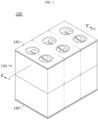
- FIG. 1 is a perspective view schematically showing a battery module according to an embodiment of the present disclosure.
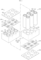
- FIG. 2 is an exploded perspective view schematically showing the battery module according to an embodiment of the present disclosure.
- FIG. 3 is a sectional view schematically showing a battery cell of the battery module according to an embodiment of the present disclosure.
- a battery module 100 includes a plurality of battery cells 110, a module case 130, and a screen member 140.
- the battery cell 110 may include an electrode assembly 116, a battery can 112, and a cap assembly 113.
- the battery cell 110 may be a cylindrical battery cell.
- the battery cell 110 electrode terminals 111 respectively located at an upper portion and a lower portion thereof.
- the plurality of battery cells 110 may be electrically connected by a connection plate 120 having a metal material.
- the plurality of battery cells 110 may be electrically connected in series, in parallel, or in series and in parallel, through the connection plate 120.
- the electrode assembly 116 may have a wound structure with a separator being interposed between a positive electrode plate and a negative electrode plate.
- a positive electrode tab 114 may be attached to the positive electrode plate and connected to the cap assembly 113, a negative electrode tab 115 may be attached to the negative electrode plate and connected to a lower end of the battery can 112.
- the battery can 112 may have an empty space so that the electrode assembly 116 may be accommodated therein.
- the battery can 112 may be configured in a cylindrical shape with an open top end.
- the battery can 112 may be made of a metal material such as steel or aluminum to secure rigidity.
- the negative electrode tab may attached to the bottom of the battery can 112, such that not only the lower portion of the battery can 112 but also the battery can 112 itself may function as a negative electrode terminal.
- the cap assembly 113 may be coupled to the open top end of the battery can 112 to seal the open top end of the battery can 112.
- the cap assembly 113 may have a circular or rectangular shape depending on the shape of the battery can 112, and may include sub-components such as a top cap C1, a vent unit C2, and a gasket C3.
- the top cap C1 may be located at an uppermost portion of the cap assembly 113 and configured to protrude upward.
- the top cap C1 may function as a positive electrode terminal in the battery cell 110.
- the top cap C1 may be electrically connected to an external device, for example another battery cell 110 or a charging device, through the connection plate 120 or the like.
- the top cap C1 may be made of, for example, a metal material such as stainless steel or aluminum. If a severe explosion or fire occurs at the battery cell 110, at least a part of the top cap C1 may be torn or detached from the battery can 112, thereby opening the battery can 112.
- the vent unit C2 may be configured to be deformed (ruptured) when the internal pressure of the battery cell 110, namely the internal pressure of the battery can 112, increases over a predetermined level, so that the gas inside the battery can 112 may be discharged to the outside through an opening D of the top cap C1.
- the predetermined level of the internal pressure may be 5 to 10 atmospheres.
- the cap assembly 113 may be detached from the battery can 112.
- the gas generated therein and fragments of the electrode assembly 116 or the like may be ejected to the outside.
- the gasket C3 may be made of a material with electrical insulation so that edge portions of the top cap C1 and the vent unit C2 may be insulated from the battery can 112.
- the cap assembly 113 may further include a current interrupt device C4.
- the current interrupt device C4 is also called CID.
- the contact between the vent unit C2 and the current interrupt device C4 may be broken, or the current interrupt device C4 may be damaged, thereby blocking the electrical connection between the vent unit C2 and the electrode assembly 116.
- the battery module 100 is not limited to the configuration of the battery cell 110 having a specific shape. That is, various types of battery cells known at the time of filing of this application may be employed in the battery module 100 according to the present disclosure.
- the module case 130 is configured to accommodate the plurality of battery cells 110 therein.
- the module case 130 may include an upper frame 133 and a lower frame 134.
- Each of the upper frame 133 and the lower frame 134 may include a plurality of hollows 135 configured so that the plurality of battery cells 110 are partially inserted therein.
- the module case 130 has a plurality of exposure holes 131.
- Each of the plurality of exposure holes 131 may be formed by perforating a part of the module case 130 so that the upper portion and the lower portion of each of the plurality of battery cells 110 may be exposed to the outside.
- a plurality of exposure holes 131 may be provided in each of the upper surface of the upper frame 133 and the lower surface of the lower frame 134 so that the electrode terminals 111 respectively provided to the upper portion and the lower portion of the plurality of battery cells 110 are exposed to the outside.
- the exposure hole 131 may be formed at a position corresponding to the vent unit C2 of the battery cell 110. For example, in the battery cell 110 of FIG.
- the vent unit C2 is located at a top end of the battery cell 110, and thus the exposure hole 131 is provided at the top end of the battery cell 110. More specifically, the exposure hole 131 may be provided at a position adjacent to the opening D of the top cap C1 through which the gas discharged from the vent unit C2 is discharged to the outside of the battery can 112.
- the exposure hole 131 may be formed in a size that may cover the entire opening D of the battery can 112.
- the top cap C1 of the battery can 112 may have a ring-shaped opening D.
- the exposure hole 131 may be configured to have a diameter greater than or equal to the diameter of the ring-shaped opening D.
- the screen member 140 is located in any one or more of the upper portion and the lower portion of the module case 130.
- each of the two screen members 140 may be located at the upper portion and the lower portion of the module case 130.
- the screen member 140 may be made of a material having high thermal conductivity while being electrically insulating.
- the screen member 140 may include a silicone resin.
- the screen member 140 may have a plate shape as a whole.
- the screen member 140 may have a plate shape extending in a horizontal direction to cover a portion of the module case 130 where the plurality of exposure holes 131 are formed.
- Each screen member 140 may have a ventilation hole 141 having a smaller size than the exposure hole 131.
- the ventilation hole 141 may have a size of 10% to 80% based on the size of the exposure hole 131, for example.
- the ventilation hole 141 may be configured to have a smaller size than the opening size of the opened portion.
- the battery module 100 includes the screen member 140.
- This structure may physically block the movement of a high-temperature active material discharged from the exploded battery cell to adjacent battery cells while maintaining the function of ejecting, namely venting, the gas and flame generated when the battery cell is ignited.
- ejecting namely venting
- the screen member 140 may allow the high-temperature gas ejected through the exposure hole 131 to pass through the ventilation hole 141, but prevents the ejected fragments of the electrode assembly from passing through the ventilation hole 141. Accordingly, in the present disclosure, it is possible to prevent chain ignition, such as propagating of thermal runaway, fire or explosion to other battery cells 110, thereby greatly improving the safety.
- FIG. 4 is a plan view schematically showing a screen member of a battery module according to another embodiment of the present disclosure.
- two or more screen members 140 may be provided in a region A where the ventilation hole 141 faces the exposure hole 131.
- the screen member 140 may have six regions A facing six exposure holes 131.
- approximately six ventilation holes 141 may be located in six regions A of the screen member 140 respectively facing the six exposure holes 131.
- the screen member 140 of the present disclosure has two or more ventilation holes 141 at positions corresponding to the exposure holes 131, when the battery cell 110 explodes, the ejected gas is effectively discharged, and fragments of the electrode assembly may be screened not to pass through the ventilation hole 141. That is, a part of the plurality of ventilation holes 141 may be formed at positions spaced apart not to face the opening of the battery cell 110 that is generated in the battery cell 110 when the battery cell 110 explodes, thereby preventing the scattered solid materials from passing through the ventilation hole 141.
- FIG. 5 is a partial sectional view schematically showing a screen member of a battery module according to still another embodiment of the present disclosure.
- the ventilation hole 141 may be configured to have a diameter gradually decreasing in an outward direction (a direction away from the battery cell 110, an upper direction in this embodiment). That is, a tapered structure K may be provided on the inner surface of the ventilation hole 141.
- a tapered structure K may be provided on the inner surface of the ventilation hole 141.
- an inlet of the ventilation hole 141 at an inner side close to the battery cell 110 may be larger than an outlet at an outer side.
- the ventilation hole 141 may have an inclined inner surface that is inclined toward the diameter center of the opening from the inlet at an inner side to the outlet at an outer side.
- the ventilation hole 141 is configured to have a diameter gradually decreasing in an outward direction, when the battery cell 110 explodes, it is possible to effectively discharge the ejected gas G but prevent the accompanying fragments of the electrode assembly from passing by being blocked by the inclined inner surface of the ventilation hole 141. That is, if the ventilation hole 141 has an inner surface of the tapered structure K so that its diameter gradually decreases in an outward direction, the area capable of screening the fragments of the electrode assembly may be further increased, thereby more effectively preventing the scattered solid materials from passing through the ventilation hole 141.
- FIG. 6 is a partial sectional view schematically showing a screen member of a battery module according to still another embodiment of the present disclosure.
- the ventilation hole 141 may be shaped so that the screen member 140 is perforated in a zigzag form along the thickness direction of the screen member 140.
- the ventilation hole 141 may be shaped so that the ventilation hole 141 is perforated to be inclined in one direction from an inlet formed close to the battery cell 110, and the penetrating direction is changed to be inclined in the other direction at the other side.
- the screen member 140 of the present disclosure since the screen member 140 of the present disclosure has the ventilation hole 141 of a zigzag form, when the battery cell 110 explodes, the ejected gas may pass through the ventilation hole 141, but accompanying fragments of the electrode assembly may be blocked by the inclined inner surface of the ventilation hole 141 not to pass. Accordingly, in the present disclosure, the high-temperature fragments of the electrode assembly do not move to other adjacent battery cells 110 due to the explosion of the battery cell 110, thereby preventing thermal runaway or fire from occurring due to the moved fragments of the electrode assembly.
- the battery module 100 of the present disclosure further includes a connection plate 120.
- the connection plate 120 is interposed between the screen member 140 and the module case 130.
- the connection plate 120 has electrical conductivity.
- the connection plate 120 may include a metal such as aluminum, copper, or nickel.
- connection plate 120 includes a body portion 121, a connection portion 122, and a connection hole 123.
- the body portion 121 may have a plate shape extending in a horizontal direction.
- the body portion 121 may be mounted to the upper portion or the lower portion of the module case 130.
- the two connection plates 120 may be mounted to the upper portion and the lower portion of the module case 130, respectively.
- connection portion 122 is formed to extend from the body portion 121 to contact the electrode terminal 111.
- the connection portion 122 may have a bifurcated structure protrusively extending from the body portion 121.
- the connection portion 122 may be welded to the electrode terminal 111. At this time, as a welding method, resistance welding may be used, for example.
- connection hole 123 may be configured such that a part of the body portion 121 is opened and the connection portion 122 is located inside the opening.
- the connection hole 123 may have an approximately circular shape.
- the connection hole 123 may be configured to face the exposure hole 131 of the module case 130.
- FIG. 7 is a partial perspective view schematically showing a connection plate of the battery module according to still another embodiment of the present disclosure.
- the connection plate 120 may include an extension portion 124 configured to cover a part of the connection hole 123.
- the extension portion 124 may have a shape protrusively extending from an edge of the connection hole 123 in a horizontal direction.
- the extension portion 124 may be a portion protruding toward the connection portion 122 from the edge of the connection hole 123.
- the connection plate 120 may be configured such that five extension portions 124 protrude from the edge of the connection hole 123 toward the connection portion 122.
- FIG. 8 is a partial sectional view schematically showing a part of the battery module, taken along the line C-C' of FIG. 1 .
- a plurality of cover portions 132 may be provided to the upper surface or the lower surface of the module case 130.
- the plurality of cover portions 132 may have a rib shape protruding toward the connection plate 120 from an outer circumference of each of the plurality of exposure holes 131.
- the cover portion 132 may be formed with a hollow penetrating in a vertical direction.
- the cover portion 132 formed on the upper surface of the module case 130 may have an open top end.
- the module case 130 may include six cover portions 132 protruding from the upper surface of the module case 130 toward the connection plate to cover the six exposure holes 131.
- connection plate 120 may be mounted on the top end of the cover portion 132. That is, the top surface of the cover portion 132 may be in contact with the lower surface of the connection plate 120.
- the screen member 140 may be mounted to the upper surface of the connection plate 120.
- the exposure hole 131, the connection hole 123 and the ventilation hole 141 may be configured to communicate with each other. Therefore, ultimately, the vent unit C2 of the battery cell 110, the opening D of the top cap C1, the exposure hole 131, and the ventilation hole 141 may all be positioned on the same line. Accordingly, the path for discharging gas is minimized, so that the gas may be smoothly discharged to the outside of the battery cell 110.
- the space between the upper surface of the upper frame 133 and the connection plate 120 may serve as a venting space in front of the battery cell 110.
- the cover portion 132 may be configured to prevent the internal material from moving to other adjacent battery cells 110 through other adjacent exposure holes 131.
- the cover portion 132 may have a cylindrical shape to surround the exposure hole 131.
- the module case 130 included in the battery module 100 according to the present disclosure includes the cover portion 132 protruding from the outer circumference of the exposure hole 131 toward the connection plate 120.
- This structure may physically block the movement of a high-temperature active material discharged from the exploded battery cell to adjacent battery cells while maintaining the function of ejecting, namely venting, the gas and flame generated when the battery cell is ignited.
- the battery cell 110 behaves abnormally to explode so that the internal material is ejected, gas and flame are ejected through the exposure hole 131, but the movement of the high-temperature active material is suppressed by the cover portion 132. Therefore, it is possible to prevent the internal material from moving to other adjacent battery cells 110 through other exposure holes 131, thereby preventing chain ignition, such as propagating of thermal runaway, fire or explosion to other battery cells 110. Accordingly, the present disclosure may greatly improve the safety.
- the cover portion 132 since the top surface of the cover portion 132 is in contact with the lower surface of the connection plate 120, even if an explosion occurs in some of the plurality of battery cells 110, it is possible to prevent the high-temperature active material, gas and flame from moving to adjacent battery cells 110 through the empty space between the connection plate 120 and the module case 130.
- the space between the upper surface of the upper frame 133 and the connection plate 120 serves as a venting space in front of the battery cell 110, and the cover portion 132 maintains the venting space in an upward direction of the battery cell 110, while making the venting space maintaining the venting space to be independent for each battery cell 110 in a lateral direction of the battery cell 110.
- the cover portion 132 may suppress that the high-temperature active material is discharged to move to adjacent battery cells 110, while maintaining the function of ejecting the gas and flame generated during ignition.
- the cover portion 132 constitutes an isolated mechanism structure for each battery cell 110 so as to suppress the scattering of an active material mass. In this way, chain ignition may be suppressed, thereby greatly improving the safety of the battery module 100 of the present disclosure.
- FIG. 9 is a vertical sectional view schematically showing a part of the battery module according to still another embodiment of the present disclosure.
- the cover portion 132 may further include a bending part 132a.
- the bending part 132a may be configured to hide a part of the exposure hole 131 of the module case 130.
- the bending part 132a may be a portion bent to extend in a horizontal direction from an end of the cover portion 132 protruding upward.
- the bending part 132a may be configured to hide a part of the open end formed by the hollow of the cover portion 132.
- the bending part 132a may be configured to be bent toward the central from the open end of the upper portion of the cover portion 132 so that the opening of the open end is more narrowed.
- the present disclosure even if an explosion occurs in some of the plurality of battery cells 110 to eject an internal material (e.g., an active material), the amount of material discharged to the outside of the module case 130 may be effectively reduced by the bending part 132a. Accordingly, it is possible to effectively reduce the movement of the internal material ejected from the exploded battery cell 110 to other adjacent battery cells 110. Ultimately, in the present disclosure, it is possible to provide the battery module 100 with greatly improved safety.
- an internal material e.g., an active material
- a battery pack includes at least one battery module 100 as described above and a battery management system (BMS) electrically connected to the battery module 100.
- the BMS may include various circuits or elements to control charging and discharging of the plurality of battery cells.
- a vehicle (not shown) according to an embodiment of the present disclosure includes at least one battery module 100 as described above and a vehicle body having an accommodation space for accommodating the battery module 100.
- the vehicle may be an electric vehicle, an electric scooter, an electric wheelchair, or an electric bike.
Landscapes
- Chemical & Material Sciences (AREA)
- Chemical Kinetics & Catalysis (AREA)
- Electrochemistry (AREA)
- General Chemical & Material Sciences (AREA)
- Battery Mounting, Suspending (AREA)
- Gas Exhaust Devices For Batteries (AREA)
- Connection Of Batteries Or Terminals (AREA)
- Sealing Battery Cases Or Jackets (AREA)
Claims (8)
- Batteriemodul (100) aufweisend:mehrere Batteriezellen (110), die jeweils Elektrodenanschlüsse (111) aufweisen, die jeweils an einem oberen Abschnitt und einem unteren Abschnitt davon ausgebildet sind;ein Modulgehäuse (130), das eingerichtet ist, die mehreren Batteriezellen (110) aufzunehmen, und das mehrere Freilegungslöcher (131) aufweist, die eingerichtet sind, den oberen Abschnitt oder den unteren Abschnitt der Batteriezelle (110) freizulegen;ein Abschirmelement (140), das an einem oder mehreren von einem oberen Abschnitt und einem unteren Abschnitt des Modulgehäuses (130) angeordnet ist und eine Plattenform aufweist, wobei das Abschirmelement (140) eingerichtet ist, ein Entlüftungsloch (141) mit einer kleineren Größe als das Freilegungsloch (131) aufzuweisen; undeine Verbindungsplatte (120), die zwischen dem Abschirmelement (140) und dem Modulgehäuse (130) angeordnet ist und eine elektrische Leitfähigkeit aufweist, wobei die Verbindungsplatte (120) einen Körperabschnitt (121), der eine Plattenform aufweist, welche sich in einer horizontalen Richtung erstreckt, einen Verbindungsabschnitt (122), der sich von dem Körperabschnitt (121) erstreckt, um den Elektrodenanschluss (111) zu kontaktieren, und ein Verbindungsloch (123) aufweist, das durch Öffnen eines Teils des Körperabschnitts (121) ausgebildet ist, so dass der Verbindungsabschnitt (122) in der Öffnung davon angeordnet ist,wobei das Modulgehäuse (130) mehrere Abdeckabschnitte (132) aufweist, die eingerichtet sind, jeweils von einem Außenumfang der mehreren Freilegungslöcher (131) in Richtung der Verbindungsplatte (120) vorzustehen, wobei der Abdeckabschnitt (132) einen Hohlraum aufweist und so geformt ist, dass er ein offenes oberes Ende aufweist.
- Batteriemodul nach Anspruch 1,
wobei zwei oder mehr Entlüftungslöcher (141) in einem Bereich des Abschirmelements (140) bereitgestellt sind, der dem Freilegungsloch (131) zugewandt ist. - Batteriemodul nach Anspruch 1,
wobei das Entlüftungsloch (141) eingerichtet ist, einen Durchmesser aufzuweisen, der in einer Auswärtsrichtung allmählich abnimmt. - Batteriemodul nach Anspruch 1,
wobei das Entlüftungsloch (141) so geformt ist, dass das Abschirmelement (140) in einer Zickzackform perforiert ist. - Batteriemodul nach Anspruch 1,
wobei die Verbindungsplatte (120) einen Verlängerungsabschnitt (124) aufweist, der eingerichtet ist, sich in einer horizontalen Richtung von einem Außenumfang des Verbindungslochs (123) hervorstehend zu erstrecken, um einen Teil des Verbindungslochs (123) zu verbergen. - Batteriemodul nach Anspruch 1,
wobei der Abdeckabschnitt (132) einen Biegeteil (132a) aufweist, der an dem offenen oberen Ende gebogen ist, um sich in einer horizontalen Richtung zu erstrecken, um einen Teil des Verbindungslochs (123) der Verbindungsplatte (120) zu verbergen. - Batteriepack aufweisend zumindest ein Batteriemodul nach einem der Ansprüche 1 bis 6.
- Fahrzeug aufweisend zumindest ein Batteriemodul nach einem der Ansprüche 1 bis 6.
Applications Claiming Priority (2)
| Application Number | Priority Date | Filing Date | Title |
|---|---|---|---|
| KR20200121768 | 2020-09-21 | ||
| PCT/KR2021/012241 WO2022060002A1 (ko) | 2020-09-21 | 2021-09-08 | 배터리 모듈, 배터리 팩, 및 이를 포함하는 자동차 |
Publications (3)
| Publication Number | Publication Date |
|---|---|
| EP4164040A1 EP4164040A1 (de) | 2023-04-12 |
| EP4164040A4 EP4164040A4 (de) | 2024-06-05 |
| EP4164040B1 true EP4164040B1 (de) | 2025-02-12 |
Family
ID=80777053
Family Applications (1)
| Application Number | Title | Priority Date | Filing Date |
|---|---|---|---|
| EP21869624.3A Active EP4164040B1 (de) | 2020-09-21 | 2021-09-08 | Batteriemodul, batteriepack und fahrzeug damit |
Country Status (8)
| Country | Link |
|---|---|
| US (1) | US20230126646A1 (de) |
| EP (1) | EP4164040B1 (de) |
| JP (1) | JP7528251B2 (de) |
| KR (1) | KR20220039588A (de) |
| CN (1) | CN115516702B (de) |
| ES (1) | ES3028986T3 (de) |
| HU (1) | HUE070838T2 (de) |
| WO (1) | WO2022060002A1 (de) |
Families Citing this family (4)
| Publication number | Priority date | Publication date | Assignee | Title |
|---|---|---|---|---|
| EP4220802A4 (de) * | 2020-09-25 | 2024-02-28 | SANYO Electric Co., Ltd. | Batteriemodul |
| KR102866051B1 (ko) * | 2021-10-25 | 2025-09-30 | 에스케이온 주식회사 | 배터리 팩 |
| CA3140540A1 (fr) | 2021-11-26 | 2023-05-26 | Stockage D'energie Evlo Inc. | Unite de stockage d'energie avec systeme de ventilation active et methode associee |
| CN217589306U (zh) * | 2022-06-15 | 2022-10-14 | 湖北亿纬动力有限公司 | 一种定向泄压的电芯及电池模组 |
Family Cites Families (16)
| Publication number | Priority date | Publication date | Assignee | Title |
|---|---|---|---|---|
| US20140193674A1 (en) * | 2011-07-29 | 2014-07-10 | Panasonic Corporation | Battery module |
| JP2014197452A (ja) * | 2011-08-03 | 2014-10-16 | パナソニック株式会社 | 電池モジュール |
| JPWO2014038184A1 (ja) | 2012-09-05 | 2016-08-08 | パナソニックIpマネジメント株式会社 | 電池モジュール |
| WO2014132649A1 (ja) | 2013-02-27 | 2014-09-04 | 三洋電機株式会社 | 電池モジュール |
| CN103474599B (zh) * | 2013-09-15 | 2018-08-31 | 宁德新能源科技有限公司 | 具有理想安全性能的锂离子电池和电池包 |
| WO2015064096A1 (ja) | 2013-10-31 | 2015-05-07 | パナソニックIpマネジメント株式会社 | 電池モジュール |
| CN106415882A (zh) * | 2014-05-08 | 2017-02-15 | 高科技股份公司 | 电池组以及组装电池组的方法 |
| JP6274064B2 (ja) | 2014-09-30 | 2018-02-07 | 豊田合成株式会社 | 電池モジュール |
| JP6414018B2 (ja) | 2015-10-29 | 2018-10-31 | トヨタ自動車株式会社 | 電池用バスバー |
| CN109417139B (zh) * | 2016-06-30 | 2021-07-23 | 三洋电机株式会社 | 电池块 |
| KR102385746B1 (ko) * | 2017-02-06 | 2022-04-11 | 삼성에스디아이 주식회사 | 이차 전지 |
| US10734066B2 (en) | 2017-07-28 | 2020-08-04 | Taiwan Semiconductor Manufacturing Co., Ltd. | Static random access memory with write assist circuit |
| KR102410972B1 (ko) * | 2017-09-22 | 2022-06-20 | 삼성에스디아이 주식회사 | 배터리 팩 |
| KR102152886B1 (ko) * | 2017-12-11 | 2020-09-07 | 삼성에스디아이 주식회사 | 배터리 팩 |
| CN208507892U (zh) * | 2018-08-09 | 2019-02-15 | 西安优必惠电子科技有限公司 | 一种新能源汽车用电池散热装置 |
| CA3126409A1 (en) * | 2019-01-29 | 2020-08-06 | Narrabundah Technology Holdings Pty Ltd | Battery pack |
-
2021
- 2021-09-08 CN CN202180033205.8A patent/CN115516702B/zh active Active
- 2021-09-08 KR KR1020210119992A patent/KR20220039588A/ko active Pending
- 2021-09-08 EP EP21869624.3A patent/EP4164040B1/de active Active
- 2021-09-08 ES ES21869624T patent/ES3028986T3/es active Active
- 2021-09-08 US US17/918,046 patent/US20230126646A1/en active Pending
- 2021-09-08 WO PCT/KR2021/012241 patent/WO2022060002A1/ko not_active Ceased
- 2021-09-08 JP JP2022563196A patent/JP7528251B2/ja active Active
- 2021-09-08 HU HUE21869624A patent/HUE070838T2/hu unknown
Also Published As
| Publication number | Publication date |
|---|---|
| JP2023522344A (ja) | 2023-05-30 |
| TW202215702A (zh) | 2022-04-16 |
| WO2022060002A1 (ko) | 2022-03-24 |
| ES3028986T3 (en) | 2025-06-23 |
| EP4164040A4 (de) | 2024-06-05 |
| CN115516702A (zh) | 2022-12-23 |
| HUE070838T2 (hu) | 2025-07-28 |
| US20230126646A1 (en) | 2023-04-27 |
| EP4164040A1 (de) | 2023-04-12 |
| KR20220039588A (ko) | 2022-03-29 |
| JP7528251B2 (ja) | 2024-08-05 |
| CN115516702B (zh) | 2025-06-10 |
Similar Documents
| Publication | Publication Date | Title |
|---|---|---|
| JP7434556B2 (ja) | バッテリーモジュール、それを含むバッテリーパック、及び自動車 | |
| EP3644403B1 (de) | Batteriemodul mit gasentladungsstruktur | |
| EP4164040B1 (de) | Batteriemodul, batteriepack und fahrzeug damit | |
| US8895181B2 (en) | Battery module | |
| US20240136649A1 (en) | Battery module and battery pack including the same | |
| KR20220163202A (ko) | 배터리 팩, 및 그것을 포함하는 자동차 | |
| EP4148887B1 (de) | Kappenanordnung und sekundärbatterie damit | |
| EP4167363B1 (de) | Batteriemodul, batteriepack und fahrzeug damit | |
| EP4379932A1 (de) | Batteriepack und vorrichtung damit | |
| JP2023551230A (ja) | バッテリーパック、電動車椅子及び自動車 | |
| KR102926483B1 (ko) | 배터리 모듈, 배터리 팩, 및 이를 포함하는 자동차 | |
| TWI911280B (zh) | 電池模組、電池組以及包括其之載具 | |
| TWI911282B (zh) | 電池模組、電池組以及包括其之車輛 | |
| US20250300314A1 (en) | Battery pack | |
| EP4621953A1 (de) | Batteriepack | |
| CN118541850A (zh) | 安全性增强的电池模块 | |
| KR20210155528A (ko) | 이차전지 및 이를 포함하는 디바이스 |
Legal Events
| Date | Code | Title | Description |
|---|---|---|---|
| STAA | Information on the status of an ep patent application or granted ep patent |
Free format text: STATUS: THE INTERNATIONAL PUBLICATION HAS BEEN MADE |
|
| PUAI | Public reference made under article 153(3) epc to a published international application that has entered the european phase |
Free format text: ORIGINAL CODE: 0009012 |
|
| STAA | Information on the status of an ep patent application or granted ep patent |
Free format text: STATUS: REQUEST FOR EXAMINATION WAS MADE |
|
| 17P | Request for examination filed |
Effective date: 20230105 |
|
| AK | Designated contracting states |
Kind code of ref document: A1 Designated state(s): AL AT BE BG CH CY CZ DE DK EE ES FI FR GB GR HR HU IE IS IT LI LT LU LV MC MK MT NL NO PL PT RO RS SE SI SK SM TR |
|
| DAV | Request for validation of the european patent (deleted) | ||
| DAX | Request for extension of the european patent (deleted) | ||
| A4 | Supplementary search report drawn up and despatched |
Effective date: 20240507 |
|
| RIC1 | Information provided on ipc code assigned before grant |
Ipc: H01M 50/271 20210101ALI20240430BHEP Ipc: H01M 50/505 20210101ALI20240430BHEP Ipc: H01M 50/503 20210101ALI20240430BHEP Ipc: H01M 50/342 20210101ALI20240430BHEP Ipc: H01M 50/502 20210101ALI20240430BHEP Ipc: H01M 50/30 20210101ALI20240430BHEP Ipc: H01M 50/20 20210101ALI20240430BHEP Ipc: H01M 50/213 20210101AFI20240430BHEP |
|
| GRAP | Despatch of communication of intention to grant a patent |
Free format text: ORIGINAL CODE: EPIDOSNIGR1 |
|
| STAA | Information on the status of an ep patent application or granted ep patent |
Free format text: STATUS: GRANT OF PATENT IS INTENDED |
|
| INTG | Intention to grant announced |
Effective date: 20241122 |
|
| GRAS | Grant fee paid |
Free format text: ORIGINAL CODE: EPIDOSNIGR3 |
|
| GRAA | (expected) grant |
Free format text: ORIGINAL CODE: 0009210 |
|
| STAA | Information on the status of an ep patent application or granted ep patent |
Free format text: STATUS: THE PATENT HAS BEEN GRANTED |
|
| P01 | Opt-out of the competence of the unified patent court (upc) registered |
Free format text: CASE NUMBER: APP_65535/2024 Effective date: 20241212 |
|
| AK | Designated contracting states |
Kind code of ref document: B1 Designated state(s): AL AT BE BG CH CY CZ DE DK EE ES FI FR GB GR HR HU IE IS IT LI LT LU LV MC MK MT NL NO PL PT RO RS SE SI SK SM TR |
|
| REG | Reference to a national code |
Ref country code: GB Ref legal event code: FG4D |
|
| REG | Reference to a national code |
Ref country code: CH Ref legal event code: EP |
|
| REG | Reference to a national code |
Ref country code: DE Ref legal event code: R096 Ref document number: 602021026176 Country of ref document: DE |
|
| REG | Reference to a national code |
Ref country code: IE Ref legal event code: FG4D |
|
| REG | Reference to a national code |
Ref country code: NL Ref legal event code: MP Effective date: 20250212 |
|
| REG | Reference to a national code |
Ref country code: ES Ref legal event code: FG2A Ref document number: 3028986 Country of ref document: ES Kind code of ref document: T3 Effective date: 20250623 |
|
| PG25 | Lapsed in a contracting state [announced via postgrant information from national office to epo] |
Ref country code: RS Free format text: LAPSE BECAUSE OF FAILURE TO SUBMIT A TRANSLATION OF THE DESCRIPTION OR TO PAY THE FEE WITHIN THE PRESCRIBED TIME-LIMIT Effective date: 20250512 |
|
| PG25 | Lapsed in a contracting state [announced via postgrant information from national office to epo] |
Ref country code: FI Free format text: LAPSE BECAUSE OF FAILURE TO SUBMIT A TRANSLATION OF THE DESCRIPTION OR TO PAY THE FEE WITHIN THE PRESCRIBED TIME-LIMIT Effective date: 20250212 |
|
| PG25 | Lapsed in a contracting state [announced via postgrant information from national office to epo] |
Ref country code: PL Free format text: LAPSE BECAUSE OF FAILURE TO SUBMIT A TRANSLATION OF THE DESCRIPTION OR TO PAY THE FEE WITHIN THE PRESCRIBED TIME-LIMIT Effective date: 20250212 |
|
| REG | Reference to a national code |
Ref country code: LT Ref legal event code: MG9D |
|
| PG25 | Lapsed in a contracting state [announced via postgrant information from national office to epo] |
Ref country code: NO Free format text: LAPSE BECAUSE OF FAILURE TO SUBMIT A TRANSLATION OF THE DESCRIPTION OR TO PAY THE FEE WITHIN THE PRESCRIBED TIME-LIMIT Effective date: 20250512 Ref country code: IS Free format text: LAPSE BECAUSE OF FAILURE TO SUBMIT A TRANSLATION OF THE DESCRIPTION OR TO PAY THE FEE WITHIN THE PRESCRIBED TIME-LIMIT Effective date: 20250612 |
|
| PG25 | Lapsed in a contracting state [announced via postgrant information from national office to epo] |
Ref country code: NL Free format text: LAPSE BECAUSE OF FAILURE TO SUBMIT A TRANSLATION OF THE DESCRIPTION OR TO PAY THE FEE WITHIN THE PRESCRIBED TIME-LIMIT Effective date: 20250212 |
|
| PGFP | Annual fee paid to national office [announced via postgrant information from national office to epo] |
Ref country code: BE Payment date: 20250425 Year of fee payment: 5 |
|
| PG25 | Lapsed in a contracting state [announced via postgrant information from national office to epo] |
Ref country code: HR Free format text: LAPSE BECAUSE OF FAILURE TO SUBMIT A TRANSLATION OF THE DESCRIPTION OR TO PAY THE FEE WITHIN THE PRESCRIBED TIME-LIMIT Effective date: 20250212 |
|
| PG25 | Lapsed in a contracting state [announced via postgrant information from national office to epo] |
Ref country code: PT Free format text: LAPSE BECAUSE OF FAILURE TO SUBMIT A TRANSLATION OF THE DESCRIPTION OR TO PAY THE FEE WITHIN THE PRESCRIBED TIME-LIMIT Effective date: 20250612 Ref country code: LV Free format text: LAPSE BECAUSE OF FAILURE TO SUBMIT A TRANSLATION OF THE DESCRIPTION OR TO PAY THE FEE WITHIN THE PRESCRIBED TIME-LIMIT Effective date: 20250212 |
|
| PG25 | Lapsed in a contracting state [announced via postgrant information from national office to epo] |
Ref country code: GR Free format text: LAPSE BECAUSE OF FAILURE TO SUBMIT A TRANSLATION OF THE DESCRIPTION OR TO PAY THE FEE WITHIN THE PRESCRIBED TIME-LIMIT Effective date: 20250513 Ref country code: BG Free format text: LAPSE BECAUSE OF FAILURE TO SUBMIT A TRANSLATION OF THE DESCRIPTION OR TO PAY THE FEE WITHIN THE PRESCRIBED TIME-LIMIT Effective date: 20250212 |
|
| REG | Reference to a national code |
Ref country code: HU Ref legal event code: AG4A Ref document number: E070838 Country of ref document: HU |
|
| REG | Reference to a national code |
Ref country code: AT Ref legal event code: MK05 Ref document number: 1767000 Country of ref document: AT Kind code of ref document: T Effective date: 20250212 |
|
| PG25 | Lapsed in a contracting state [announced via postgrant information from national office to epo] |
Ref country code: SE Free format text: LAPSE BECAUSE OF FAILURE TO SUBMIT A TRANSLATION OF THE DESCRIPTION OR TO PAY THE FEE WITHIN THE PRESCRIBED TIME-LIMIT Effective date: 20250212 |
|
| PG25 | Lapsed in a contracting state [announced via postgrant information from national office to epo] |
Ref country code: SM Free format text: LAPSE BECAUSE OF FAILURE TO SUBMIT A TRANSLATION OF THE DESCRIPTION OR TO PAY THE FEE WITHIN THE PRESCRIBED TIME-LIMIT Effective date: 20250212 |
|
| PG25 | Lapsed in a contracting state [announced via postgrant information from national office to epo] |
Ref country code: DK Free format text: LAPSE BECAUSE OF FAILURE TO SUBMIT A TRANSLATION OF THE DESCRIPTION OR TO PAY THE FEE WITHIN THE PRESCRIBED TIME-LIMIT Effective date: 20250212 |
|
| PGFP | Annual fee paid to national office [announced via postgrant information from national office to epo] |
Ref country code: DE Payment date: 20250820 Year of fee payment: 5 |
|
| PG25 | Lapsed in a contracting state [announced via postgrant information from national office to epo] |
Ref country code: IT Free format text: LAPSE BECAUSE OF FAILURE TO SUBMIT A TRANSLATION OF THE DESCRIPTION OR TO PAY THE FEE WITHIN THE PRESCRIBED TIME-LIMIT Effective date: 20250212 |
|
| PGFP | Annual fee paid to national office [announced via postgrant information from national office to epo] |
Ref country code: HU Payment date: 20250929 Year of fee payment: 5 Ref country code: GB Payment date: 20250820 Year of fee payment: 5 |
|
| PG25 | Lapsed in a contracting state [announced via postgrant information from national office to epo] |
Ref country code: AT Free format text: LAPSE BECAUSE OF FAILURE TO SUBMIT A TRANSLATION OF THE DESCRIPTION OR TO PAY THE FEE WITHIN THE PRESCRIBED TIME-LIMIT Effective date: 20250212 |
|
| PGFP | Annual fee paid to national office [announced via postgrant information from national office to epo] |
Ref country code: FR Payment date: 20250821 Year of fee payment: 5 |
|
| PG25 | Lapsed in a contracting state [announced via postgrant information from national office to epo] |
Ref country code: CZ Free format text: LAPSE BECAUSE OF FAILURE TO SUBMIT A TRANSLATION OF THE DESCRIPTION OR TO PAY THE FEE WITHIN THE PRESCRIBED TIME-LIMIT Effective date: 20250212 Ref country code: EE Free format text: LAPSE BECAUSE OF FAILURE TO SUBMIT A TRANSLATION OF THE DESCRIPTION OR TO PAY THE FEE WITHIN THE PRESCRIBED TIME-LIMIT Effective date: 20250212 |
|
| PG25 | Lapsed in a contracting state [announced via postgrant information from national office to epo] |
Ref country code: RO Free format text: LAPSE BECAUSE OF FAILURE TO SUBMIT A TRANSLATION OF THE DESCRIPTION OR TO PAY THE FEE WITHIN THE PRESCRIBED TIME-LIMIT Effective date: 20250212 |
|
| PG25 | Lapsed in a contracting state [announced via postgrant information from national office to epo] |
Ref country code: SK Free format text: LAPSE BECAUSE OF FAILURE TO SUBMIT A TRANSLATION OF THE DESCRIPTION OR TO PAY THE FEE WITHIN THE PRESCRIBED TIME-LIMIT Effective date: 20250212 |
|
| REG | Reference to a national code |
Ref country code: DE Ref legal event code: R097 Ref document number: 602021026176 Country of ref document: DE |
|
| PLBE | No opposition filed within time limit |
Free format text: ORIGINAL CODE: 0009261 |
|
| STAA | Information on the status of an ep patent application or granted ep patent |
Free format text: STATUS: NO OPPOSITION FILED WITHIN TIME LIMIT |
|
| 26N | No opposition filed |
Effective date: 20251113 |
|
| PGFP | Annual fee paid to national office [announced via postgrant information from national office to epo] |
Ref country code: ES Payment date: 20251007 Year of fee payment: 5 |