EP4163409B1 - Verschleissfestes element - Google Patents
Verschleissfestes element Download PDFInfo
- Publication number
- EP4163409B1 EP4163409B1 EP21822810.4A EP21822810A EP4163409B1 EP 4163409 B1 EP4163409 B1 EP 4163409B1 EP 21822810 A EP21822810 A EP 21822810A EP 4163409 B1 EP4163409 B1 EP 4163409B1
- Authority
- EP
- European Patent Office
- Prior art keywords
- mass
- less
- wear
- based alloy
- alloy material
- Prior art date
- Legal status (The legal status is an assumption and is not a legal conclusion. Google has not performed a legal analysis and makes no representation as to the accuracy of the status listed.)
- Active
Links
Images


Classifications
-
- C—CHEMISTRY; METALLURGY
- C23—COATING METALLIC MATERIAL; COATING MATERIAL WITH METALLIC MATERIAL; CHEMICAL SURFACE TREATMENT; DIFFUSION TREATMENT OF METALLIC MATERIAL; COATING BY VACUUM EVAPORATION, BY SPUTTERING, BY ION IMPLANTATION OR BY CHEMICAL VAPOUR DEPOSITION, IN GENERAL; INHIBITING CORROSION OF METALLIC MATERIAL OR INCRUSTATION IN GENERAL
- C23C—COATING METALLIC MATERIAL; COATING MATERIAL WITH METALLIC MATERIAL; SURFACE TREATMENT OF METALLIC MATERIAL BY DIFFUSION INTO THE SURFACE, BY CHEMICAL CONVERSION OR SUBSTITUTION; COATING BY VACUUM EVAPORATION, BY SPUTTERING, BY ION IMPLANTATION OR BY CHEMICAL VAPOUR DEPOSITION, IN GENERAL
- C23C4/00—Coating by spraying the coating material in the molten state, e.g. by flame, plasma or electric discharge
- C23C4/12—Coating by spraying the coating material in the molten state, e.g. by flame, plasma or electric discharge characterised by the method of spraying
- C23C4/123—Spraying molten metal
-
- B—PERFORMING OPERATIONS; TRANSPORTING
- B32—LAYERED PRODUCTS
- B32B—LAYERED PRODUCTS, i.e. PRODUCTS BUILT-UP OF STRATA OF FLAT OR NON-FLAT, e.g. CELLULAR OR HONEYCOMB, FORM
- B32B15/00—Layered products comprising a layer of metal
- B32B15/01—Layered products comprising a layer of metal all layers being exclusively metallic
-
- C—CHEMISTRY; METALLURGY
- C22—METALLURGY; FERROUS OR NON-FERROUS ALLOYS; TREATMENT OF ALLOYS OR NON-FERROUS METALS
- C22C—ALLOYS
- C22C27/00—Alloys based on rhenium or a refractory metal not mentioned in groups C22C14/00 or C22C16/00
- C22C27/06—Alloys based on chromium
-
- C—CHEMISTRY; METALLURGY
- C23—COATING METALLIC MATERIAL; COATING MATERIAL WITH METALLIC MATERIAL; CHEMICAL SURFACE TREATMENT; DIFFUSION TREATMENT OF METALLIC MATERIAL; COATING BY VACUUM EVAPORATION, BY SPUTTERING, BY ION IMPLANTATION OR BY CHEMICAL VAPOUR DEPOSITION, IN GENERAL; INHIBITING CORROSION OF METALLIC MATERIAL OR INCRUSTATION IN GENERAL
- C23C—COATING METALLIC MATERIAL; COATING MATERIAL WITH METALLIC MATERIAL; SURFACE TREATMENT OF METALLIC MATERIAL BY DIFFUSION INTO THE SURFACE, BY CHEMICAL CONVERSION OR SUBSTITUTION; COATING BY VACUUM EVAPORATION, BY SPUTTERING, BY ION IMPLANTATION OR BY CHEMICAL VAPOUR DEPOSITION, IN GENERAL
- C23C30/00—Coating with metallic material characterised only by the composition of the metallic material, i.e. not characterised by the coating process
-
- C—CHEMISTRY; METALLURGY
- C23—COATING METALLIC MATERIAL; COATING MATERIAL WITH METALLIC MATERIAL; CHEMICAL SURFACE TREATMENT; DIFFUSION TREATMENT OF METALLIC MATERIAL; COATING BY VACUUM EVAPORATION, BY SPUTTERING, BY ION IMPLANTATION OR BY CHEMICAL VAPOUR DEPOSITION, IN GENERAL; INHIBITING CORROSION OF METALLIC MATERIAL OR INCRUSTATION IN GENERAL
- C23C—COATING METALLIC MATERIAL; COATING MATERIAL WITH METALLIC MATERIAL; SURFACE TREATMENT OF METALLIC MATERIAL BY DIFFUSION INTO THE SURFACE, BY CHEMICAL CONVERSION OR SUBSTITUTION; COATING BY VACUUM EVAPORATION, BY SPUTTERING, BY ION IMPLANTATION OR BY CHEMICAL VAPOUR DEPOSITION, IN GENERAL
- C23C4/00—Coating by spraying the coating material in the molten state, e.g. by flame, plasma or electric discharge
- C23C4/04—Coating by spraying the coating material in the molten state, e.g. by flame, plasma or electric discharge characterised by the coating material
- C23C4/06—Metallic material
- C23C4/08—Metallic material containing only metal elements
-
- C—CHEMISTRY; METALLURGY
- C23—COATING METALLIC MATERIAL; COATING MATERIAL WITH METALLIC MATERIAL; CHEMICAL SURFACE TREATMENT; DIFFUSION TREATMENT OF METALLIC MATERIAL; COATING BY VACUUM EVAPORATION, BY SPUTTERING, BY ION IMPLANTATION OR BY CHEMICAL VAPOUR DEPOSITION, IN GENERAL; INHIBITING CORROSION OF METALLIC MATERIAL OR INCRUSTATION IN GENERAL
- C23C—COATING METALLIC MATERIAL; COATING MATERIAL WITH METALLIC MATERIAL; SURFACE TREATMENT OF METALLIC MATERIAL BY DIFFUSION INTO THE SURFACE, BY CHEMICAL CONVERSION OR SUBSTITUTION; COATING BY VACUUM EVAPORATION, BY SPUTTERING, BY ION IMPLANTATION OR BY CHEMICAL VAPOUR DEPOSITION, IN GENERAL
- C23C4/00—Coating by spraying the coating material in the molten state, e.g. by flame, plasma or electric discharge
- C23C4/12—Coating by spraying the coating material in the molten state, e.g. by flame, plasma or electric discharge characterised by the method of spraying
- C23C4/134—Plasma spraying
-
- B—PERFORMING OPERATIONS; TRANSPORTING
- B23—MACHINE TOOLS; METAL-WORKING NOT OTHERWISE PROVIDED FOR
- B23K—SOLDERING OR UNSOLDERING; WELDING; CLADDING OR PLATING BY SOLDERING OR WELDING; CUTTING BY APPLYING HEAT LOCALLY, e.g. FLAME CUTTING; WORKING BY LASER BEAM
- B23K11/00—Resistance welding; Severing by resistance heating
- B23K11/0013—Resistance welding; Severing by resistance heating welding for purposes other than joining, e.g. build-up welding
Definitions
- the present invention relates to a technique of a wear-resistant material, and particularly relates to a wear-resistant member using a Cr (chromium)-based alloy material and a mechanical device using the wear-resistant member.
- a sliding member, a rolling member, and a valve member are very important members that influence the operation accuracy of the mechanical devices and strongly affect the maintenance cycle.
- the wear resistance of the sliding member, the rolling member, and the valve member is one of important characteristics related to the life of the members.
- a method of improving the wear resistance of a sliding member, a rolling member, and a valve member there are a method of forming all the members from a material having excellent wear resistance, and a method of producing a sliding member, a rolling member, and a valve member by using a conventional material excellent in terms of mechanical strength, toughness, and cost as a base material, and forming a covering layer of a material having excellent wear resistance on sliding and rolling contact surfaces of the members, or a valve body surface or a valve seat surface.
- Co cobalt-based alloy material
- STELLITE registered trademark
- TRIBALOY registered trademark
- PTL 1 JP 2009-052084 A discloses a metal mold member for resin molding, comprising an Ni-Cr-Al-based alloy having a component composition including, by mass%: more than 35 to 50% of Cr; 0.1 to 6% of Al (aluminum); more than 0.1 to 1% of Fe (iron); 0.001 to 0.015% of C (carbon); 0.01 to 0.2% of Si (silicon); 0.01 to 0.2% of Mn (manganese); 0.001 to 0.03% of Mg (magnesium); and 0.001 to 0.01% of N (nitrogen); and, as necessary, including more than 0.1 to 2% of (A) Mo (molybdenum) and more than 0.1 to 5% of (B) Cu (copper), wherein one or two of the above (A) and (B) are contained, the balance includes Ni (nickel)
- PTL 2 JP H5-271841 A discloses a high toughness Cr-based alloy for hard facing, comprising: 30.0 to 48.0 wt% of Ni; 1.5 to 15.0 wt% of W (tungsten); and/or 1.0 to 6.5 wt% of Mo, a total of W and Mo being 15.0 wt% or less, the alloy further including one or two or more of Fe, Co, C, B (boron), Al, Si, Nb (niobium), and Ti (titanium) as necessary, further including 0.01 to 0.12 wt% of one or two or more of Al, Y (yttrium), misch metal, Ti, Zr (zirconium), and Hf (hafnium) as necessary in the case of a powder used for powder buildup welding, and additionally including 0.01 to 0.1 wt% of O as necessary, the balance being 40 wt% or more of Cr.
- PTL 3 ( WO 2019/189531 A1 ) concerns a Cr-Ni based alloy comprising, by mass%: more than 40.0% and no more than 65.0% of Cr; 0-35.0% of Fe; 0% or more and less than 2.0% of Mn; any of over 1.1% and no more than 4.0% of C, 0.7-3.0% of B, and 0.5-2.5% of C; and more than 0% and no more than 20% of Nb, wherein the remainder is made up of Ni and unavoidable impurities, and said Ni is 15% or more.
- the metal mold member for resin molding including an Ni-Cr-Al-based alloy in PTL 1 has excellent corrosion resistance to hydrogen fluoride, and has hardness substantially equivalent to that of the conventional metal mold member for resin molding. It is considered that the use of a mold made of the Ni-Cr-Al-based alloy enables the consumption of the mold during molding of a resin (particularly, a fluorine resin) to be suppressed as compared with that in the past.
- the high toughness Cr-based alloy for hard facing of PTL 2 has toughness, wear resistance, corrosion resistance, and powder buildup weldability superior to conventional materials. Further, it is considered that the alloy may be used as a sintered component by powder metallurgy or a cast component by precision casting.
- an object of the present invention is to provide a wear-resistant member using a Cr-based alloy material that does not contain a Co component (i.e., in which the cost can be reduced as compared with the Co-based alloy material) and has wear resistance equal to or more than that of the conventional Co-based alloy material, and a mechanical device using the wear-resistant member.
- the wear-resistant member (I) according to the present invention can be improved and modified as follows.
- Another aspect of the present invention is to provide a mechanical device including: a sliding member; a rolling member; or a valve member, in which the sliding member, the rolling member, or the valve member is the wear-resistant member described above.
- a wear-resistant member using a Cr-based alloy material that does not contain a Co component (i.e., in which the cost can be reduced as compared with the Co-based alloy material) and has wear resistance equal to or more than that of the conventional Co-based alloy material, and a mechanical device using the wear-resistant member.
- the present inventors have extensively conducted studies on the relationship among the chemical composition, metal structure form, and wear resistance of a member using a Cr-based alloy material which does not contain Co, but contains Cr as a main component (component having the maximum content rate), particularly a Cr-based alloy material which contains more than 40 mass% of Cr, and completed the present invention.
- the Cr-based alloy material used in the present invention is an alloy that consists of Cr as a component with the maximum content rate, and essential components: Ni, Fe, Nb, Ti, and C, in addition to Cr, an optional component: Mn, and impurities, and optionally one or more of additional optional components: Cu, Si, Sn, and Al.
- the total content rate of impurities is preferably 1 mass% or less.
- the target wear-resistant member is a member in which a covering layer is formed on a metal base material, and the metal base material and the covering layer are dissimilar alloys (alloys having compositions different from each other), interdiffusion of alloy components may occur in the vicinity of the interface between the covering layer and the metal base material in the process of forming the covering layer, and there is a possibility that the chemical composition in the vicinity of the interface may deviate from the original chemical composition.
- the effective diffusion time time during which substantial diffusion occurs
- the influence of diffusion becomes extremely small as the thickness of the covering layer is increased (e.g., by multilayering the covering layer).
- the wear resistance is discussed as in the present invention, the characteristics of the surface layer region of the member are important.
- the surface layer region of the covering layer e.g., a region of 10% of the covering layer thickness from the outermost surface of the covering layer
- composition (each component) of the Cr-based alloy material used in the present invention will be described.
- the remaining components other than the elements described below are impurities that are difficult to control.
- the Cr component is a component containing the Cr-based alloy material of the present invention with the maximum content rate and is cheaper than Co, so it is advantageous in that the material cost can be reduced as compared with the conventional Co-based alloy material.
- containing of Cr as a component with the maximum content rate also produces an effect such that a passive oxide film is easily formed on the surface of the Cr-based alloy material, and the corrosion resistance is improved.
- the content rate of the Cr is more than 4C mass%, preferably 45 mass% or more, and more preferably 50 mass% or more.
- the content rate of the Cr is 40 mass% or less, the cost reduction effect is weakened, and the effect of improving corrosion resistance is not sufficient.
- the content rate of the Cr is more than 65 mass%, the melting point of the alloy becomes too high and the manufacturability of the Cr-based alloy material is deteriorated (production cost is increased), and thus the Cr content is 65 mass% or less.
- Ni 15 mass% or more and 40 mass% or less
- the Ni component is one of the main components constituting a parent phase (a ferrite phase or a mixed phase of ferrite and austenite phases) of the Cr-based alloy material of the present invention, and is a component contributing to the improvement in ductility and toughness of the parent phase.
- the content rate of the Ni is lower than the content rate of the Cr described above and higher than the content rate of the Fe described later. Specifically, the content rate of the Ni is mass% or more, preferably 20 mass% or more, and more preferably 25 mass% or more. When the content rate of the Ni is less than 15 mass%, the ductility and toughness of the Cr-based alloy material become insufficient. Meanwhile, when the content rate of the Ni is more than 40 mass%, the wear resistance of the Cr-based alloy material becomes insufficient, and thus the content rate of the Ni is 40 mass% or less.
- the Fe component is also one of the main components constituting the parent phase of the Cr-based alloy material of the present invention, and is a component contributing to securing toughness and hardness.
- the content rate of the Fe is more than 0 mass%, preferably 10 mass% or more, and more preferably 15 mass% or more.
- the Cr-based alloy material does not contain any Fe component (when the content rate of the Fe is 0 mass%), the wear resistance of the Cr-based alloy material becomes insufficient. Meanwhile, the content rate of the Fe is 30 mass% or less, preferably 20 mass% or less, and more preferably 17 mass% or less.
- ⁇ phase an intermetallic compound phase based on a FeCr phase
- ⁇ phase embrittlement an intermetallic compound phase based on a FeCr phase
- Nb 5 mass% or more and 16 mass% or less
- the Nb component is an important component that chemically combines with the C component to be described later to form and precipitate an Nb carbide phase (e.g., an NbC phase), and contributes to improvement in the hardening and wear resistance of the Cr-based alloy material. Further, the Nb component solid-solved in the parent phase also has an effect of contributing to improvement of toughness.
- the content rate of the Nb is 5 mass% or more, and preferably 6 mass% or more. When the content rate of the Nb is less than 5 mass%, the improvement in the hardening and wear resistance of the Cr-based alloy material becomes insufficient. Meanwhile, the content rate of the Nb is 16 mass% or less, and preferably 12 mass% or less. When the content rate of the Nb is more than 16 mass%, the ductility and toughness of the Cr-based alloy material become insufficient.
- the mass ratio C/Nb of the content rate of the Nb and the content rate of the C to be described later is preferably 0.11 or more and 0.16 or less, and more preferably 0.12 or more and 0.14 or less.
- the mass ratio C/Nb is less than 0.11, the amount of the Nb carbide phase formed is insufficient, and the effect of improving the hardening and wear resistance of the Cr-based alloy material becomes insufficient.
- the mass ratio C/Nb is more than 0.16, a Cr carbide phase (e.g., a Cr 7 C 3 phase or a Cr 23 C 6 phase) is formed and precipitated by an excessive amount of C component, causing a decrease in corrosion resistance of the Cr-based alloy material.
- the C component is an important component that chemically combines with the above-described Nb component to form and precipitate an Nb carbide phase, and contributes to improvement in the hardening and wear resistance of the Cr-based alloy material. Further, the C component also has an effect of contributing to the hardening of the Cr-based alloy material even when the C component is solid-solved in the parent phase.
- the content rate of the C is 0.6 mass% or more, and preferably 0.7 mass% or more. When the content rate of the C is less than 0.6 mass%, the improvement in the hardening and wear resistance of the Cr-based alloy material becomes insufficient. Meanwhile, the content rate of the C is 2.5 mass% or less, preferably 2 mass% or less, and more preferably 1.5 mass% or less. When the content rate of the C is more than 2.5 mass%, the Cr carbide phase is excessively formed/precipitated, causing a decrease in corrosion resistance of the Cr-based alloy material.
- the mass ratio C/Nb of the content rate of the C and the content rate of the Nb is preferably 0.11 or more and 0.16 or less, and more preferably 0.12 or more and 0.14 or less.
- the Ti component is a component that chemically combines with oxygen in the Cr-based alloy material to form fine Ti oxide particles, and plays a role of trapping and stabilizing an excessive amount of oxygen which does not contribute to the positive effect (so-called role of deoxygenation). Additionally, the Ti oxide particles dispersed and formed serve as a starting point (species) for formation of the Nb carbide phase, and have an effect of contributing to fine dispersion/precipitation of the Nb carbide phase.
- the present invention does not deny that there is a possibility that a part of the Ti component forms a carbide (e.g., TiC or (Nb,Ti)C).
- the content rate of the Ti is 0.1 mass% or more, and preferably 0.2 mass% or more.
- the content rate of the Ti is less than 0.1 mass%, the amount of Ti oxide particles formed is insufficient, and thus the fine dispersion/precipitation of the Nb carbide phase becomes insufficient (large lump-like Nb carbide phase particles are likely to be precipitated).
- the improvement in the hardening and wear resistance of the Cr-based alloy material becomes insufficient.
- the content rate of the Ti is 0.9 mass% or less, preferably 0.7 mass% or less, and more preferably 0.5 mass% or less.
- the mass ratio Ti/Nb of the content rate of the Ti and the content rate of the Nb is preferably 0.0062 or more and 0.063 or less, and more preferably 0.01 or more and 0.05 or less.
- the mass ratio Ti/Nb is less than 0.0062, the lump-like Nb carbide phase particles are likely to be coarsened.
- the mass ratio Ti/Nb is more than 0.063, the content rate of the Ti in the Nb carbide phase particles increases, and the Nb carbide phase particles are likely to be unevenly distributed on the surface of the solidified Cr-based alloy material.
- the Mn component is an optional component of the Cr-based alloy material, and is a component that chemically combines with sulfur or oxygen to form fine particles of the compound and plays a role of trapping and stabilizing an excessive amount of sulfur or oxygen which does not contribute to the positive effect (so-called role of desulfurization/deoxygenation).
- the trapping and stabilizing of sulfur or oxygen contribute to the improvement in the corrosiveness, ductility and toughness of the Cr-based alloy material.
- the content rate of the Mn is preferably 0.05 mass% or more to reliably exhibit the effect of containing Mn.
- the content rate of the Mn is 2 mass% or less, preferably 1 mass% or less, and more preferably 0.5 mass% or less.
- coarse particles of a sulfide e.g., MnS
- MnS a sulfide
- Impurities 1 mass% or less in total
- Typical impurities in the Cr-based alloy material of the present invention include N, O, P, S, and Ta. Next, these impurities will be briefly described.
- the N component is an impurity component that lowers mechanical characteristics (e.g., ductility and toughness) of the Cr-based alloy material in a case where the N component chemically combines with a constituent of the Cr-based alloy material to form coarse particles of a nitride phase (e.g., a Cr nitride phase). Meanwhile, controlling of the content rate of the N to 0.04 mass% or less makes it possible to cause the component to be solid-solved in the parent phase or to form fine particles of the nitride phase, and there is also yielded an effect of improving mechanical characteristics (e.g., hardness).
- mechanical characteristics e.g., ductility and toughness
- the O component is an impurity component that lowers mechanical characteristics (e.g., ductility and toughness) of the Cr-based alloy material in a case where the O component chemically combines with a constituent of the Cr-based alloy material to form coarse particles of oxide phase (e.g., Fe oxide). Meanwhile, controlling of the content rate of the O to 0.02 mass% or less makes it possible to form fine particles of the oxide phase, and there is also yielded an effect of improving mechanical characteristics (e.g., hardness).
- mechanical characteristics e.g., ductility and toughness
- the P component is an impurity component that is likely to segregate at the crystal grain boundary of the Cr-based alloy material and lowers mechanical characteristics (e.g., ductility and toughness) or corrosion resistance of the crystal grain boundary. Controlling of the content rate of the P to 0.04 mass% or less makes it possible to suppress these negative effects.
- the S component is an impurity component that is likely to chemically combine with a constituent of the Cr-based alloy material to form a sulfide (e.g., Fe sulfide) having a relatively low melting point, and lowers the mechanical characteristics or corrosion resistance of the Cr-based alloy material. Controlling of the content rate of the S to 0.005 mass% or less makes it possible to suppress these negative effects.
- a sulfide e.g., Fe sulfide
- Ta 0.2 mass% or less
- the Ta component is one component contained in niobium ore (e.g., pyrochlore), and is an impurity component that is likely to be mixed into the Nb raw material.
- niobium ore e.g., pyrochlore
- the Ta component is a component which is not actively added, and whose acceptable amount is 0.2 mass% or less.
- the Cr-based alloy material of the present invention may further contain one or more of additional optional components: Cu, Si, Sn, and Al. Next, these additional optional components will be briefly described.
- Cu 0.1 mass% or more and 5 mass% or less
- the Cu component is one of the additional optional components in the Cr-based alloy material, and is a component contributing to the improvement in corrosion resistance.
- the content rate of the Cu is 0.1 mass% or more and 5 mass% or less.
- the content rate of the Cu is less than 0.1 mass%, it is only difficult to clarify the effect based on Cu (no particular problem occurs).
- the content rate of the Cu is more than 5 mass%, a Cu precipitate is likely to be formed. This causes a decrease in the ductility and toughness of the Cr-based alloy material.
- Si 0.1 mass% or more and 1 mass% or less
- the Si component is also one of the additional optional components in the Cr-based alloy material, and is a component that plays a role of deoxygenation.
- the content rate of the Si is 0.1 mass% or more and 1 mass% or less.
- the content rate of the Si is less than 0.1 mass%, it is only difficult to clarify the effect based on Si (no particular problem occurs).
- the content rate of the Si is more than 1 mass%, coarse particles of an oxide (e.g., SiO 2 ) are formed. This causes a decrease in the ductility and toughness of the Cr-based alloy material.
- Al 0.005 mass% or more and 0.05 mass% or less
- the Al component is also one of the additional optional components in the Cr-based alloy material, and is a component contributing to the improvement in deoxygenation when combined with Mn or Si.
- the content rate of the Al is 0.005 mass% or more and 0.05 mass% or less.
- the content rate of the Al is less than 0.005 mass%, it is only difficult to clarify the effect based on Al (no particular problem occurs).
- the content rate of the Al is more than 0.05 mass%, coarse particles of an oxide or a nitride (e.g., Al 2 O 3 or AlN) are formed. This causes a decrease in the ductility and toughness of the Cr-based alloy material.
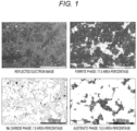
- FIG. 1 shows scanning electron microscope (SEM) observation images showing an example of a cross-sectional microstructure of a Cr-based alloy material in the present invention, and the images are a reflected electron image, a ferrite phase map, an Nb carbide phase map, and an austenite phase map, respectively.
- the parent phase includes a mixed phase of a ferrite and an austenite phase, and the Nb carbide phase is dispersed and precipitated in the parent phase.
- the ferrite phase has an area percentage of 77.5%
- the austenite phase has an area percentage of 15.5%
- the Nb carbide phase has an area percentage of 7.0%.
- the Nb carbide phase is mainly precipitated in a dendritic/leaf vein form, and is precipitated in a granular form in some places.
- the Nb carbide phase is finely dispersed and precipitated over the entire parent phase.
- the Cr-based alloy material in the present invention exhibits excellent wear resistance due to the fine dispersion/precipitation of the Nb carbide phase.
- the area percentage of the Nb carbide phase precipitated is preferably 4% or more and 30% or less, and more preferably 5% or more and 20% or less.
- the area percentage of the Nb carbide phase precipitated is less than 4%, the effect of improving the wear resistance of the Cr-based alloy material cannot be sufficiently produced.
- the area percentage of the Nb carbide phase precipitated is more than 30%, the Nb carbide phase in a coarse granular form is likely to be precipitated, and the ductility and toughness of the Cr-based alloy material become insufficient.
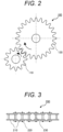
- FIG. 2 is a schematic cross-sectional view illustrating a power transmission device as an example of a mechanical device according to the present invention.
- a first gear 110 and a second gear 120 including the Cr-based alloy material of the present invention are combined, thereby forming a gear mechanism 100 having excellent wear resistance.
- FIG. 2 illustrates the gear mechanism by a spur gear
- the power transmission device according to the present invention is not limited to the spur gear, and may be another gear (e.g., an internal gear, a helical gear, a screw gear, a bevel gear, etc.).
- FIG. 3 is a schematic cross-sectional view illustrating another power transmission device as an example of the mechanical device according to the present invention.
- the use of a chain plate 210, a chain pin 210, and a chain roller 230 including the Cr-based alloy material of the present invention allows for the formation of a roller chain 200 having excellent wear resistance.
- FIG. 4 is a schematic cross-sectional view illustrating a bearing device as an example of the mechanical device according to the present invention.
- a bearing inner ring 310 and a bearing outer ring 320 each having a covering layer 10 including the Cr-based alloy material of the present invention on its rolling contact surface, (each being one type of the wear-resistant member according to the present invention) allows for the formation of a bearing device 300 having excellent wear resistance.
- FIG. 4 illustrates the bearing device, the bearing device according to the present invention is not limited to the bearing device, and may be a slide bearing device.
- FIG. 5 is a schematic cross-sectional view illustrating a fluid device as an example of the mechanical device according to the present invention.
- the use of a flow path member 410 in which the covering layer 10 including the Cr-based alloy material is provided on an inner surface and an impeller 420 in which the covering layer 10 including the Cr-based alloy material is provided on an outer surface allows for the formation of a pump device 400 having excellent wear resistance.
- the fluid substance is not particularly limited, and may be, for example, a gas, a liquid, a powder, or a fluid in which two or more of them are mixed.
- the bearing device 300 may be used as a bearing of a rotary shaft of the impeller 420.
- FIG. 6 is a schematic cross-sectional view illustrating a machine tool device as an example of the mechanical device according to the present invention.
- a mold 510 one type of the wear-resistant member according to the present invention
- the covering layer 10 including the Cr-based alloy material is provided on an action surface (surface in contact with a processed surface) allows for the formation of a molding device 500 having excellent wear resistance.
- FIG. 7 is a schematic cross-sectional view illustrating a valve device as an example of the mechanical device according to the present invention.
- the use of a fuel injection valve 610 and a fuel injection valve seat body 620 using the Cr-based alloy material of the present invention allows for the formation of a fuel injection device 600 having excellent wear resistance.
- Each of the fuel injection valve 610 and the fuel injection valve seat body 620 may have a structure in which the covering layer including the Cr-based alloy material is formed on a metal base material, or may be formed of the Cr-based alloy material alone.
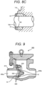
- FIG. 8A is a schematic cross-sectional view illustrating another valve device as an example of the mechanical device according to the present invention
- FIG. 8B is an enlarged schematic cross-sectional view of a valve body of the valve device of FIG. 8A
- FIG. 8C is an enlarged schematic cross-sectional view of a valve seat of the valve device of FIG. 8A .
- a valve rod 720 is disposed in a valve box 710, and a valve body 730 is disposed at an end of the valve rod 720.
- the mechanism is such that when the valve body 730 is inserted into or removed from valve seats 740, the fluid in a flow path 750 flows or stops flowing. More specifically, as illustrated in FIGS. 8B and 8C , the covering layers 10 including the Cr-based alloy material are formed at portions where the valve body 730 slides on or is sealed with the valve seats 740 (each being one type of the wear-resistant member according to the present invention). As a result, the valve device 700 having excellent wear resistance is obtained.
- FIG. 9 is a schematic cross-sectional view illustrating another valve device as an example of a mechanical device according to the present invention.
- a valve device 800 of FIG. 9 is a check valve, and, in a valve box 810, a valve body 830 is disposed at an end of a valve body support 820 rotatably attached to the valve box 810.
- the mechanism is such that the valve body 830 opens and the fluid flows in the direction from a flow path 850a toward a flow path 850b, whereas the valve body 830 closes with respect to annular valve seats 840 disposed at an end of the flow path 850a to stop the fluid flowing in the direction from the flow path 850b toward the flow path 850a.
- the valve body 830 and the valve seats 840 (each being one type of the wear-resistant member according to the present invention) have the covering layers 10 including the Cr-based alloy material formed at portions in contact with each other. As a result, the valve device 800 having excellent wear resistance is obtained.
- FIG. 10 is a schematic cross-sectional view illustrating another valve device as an example of a mechanical device according to the present invention.
- a valve device 900 of FIG. 10 is an open safety valve, and a valve body 930 is pressed against valve seats 940 by a pressing mechanism (a pressing spring 960a, an upper spring bearing 960b, and a lower spring bearing 960c) via a valve rod 920 in a valve box 910.
- a pressing mechanism a pressing spring 960a, an upper spring bearing 960b, and a lower spring bearing 960c
- the valve body 930 and the valve seats 940 (each being one type of the wear-resistant member according to the present invention) have the covering layers 10 including the Cr-based alloy material formed at portions in contact with each other. As a result, the valve device 900 having excellent wear resistance is obtained.
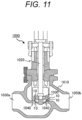
- FIG. 11 is a schematic cross-sectional view illustrating another valve device as an example of a mechanical device according to the present invention.
- a valve device 1000 of FIG. 11 is a ball-type valve, a valve rod 1020 is disposed in a valve box 1010, and a valve body 1030 is disposed at an end of the valve rod 1020.
- the mechanism is such that when the valve body 1030 is loaded and sealed with respect to valve seats 1040, the fluid in a flow path 1050a is stopped, whereas when the valve body 1030 is unloaded and opened with respect to the valve seats 1040, the fluid in the flow path 1050a flows through a flow path 1050b.
- the valve body 1030 and the valve seats 1040 (each being one type of the wear-resistant member according to the present invention) have the covering layers 10 including the Cr-based alloy material formed at portions in contact with each other. As a result, the valve device 1000 having excellent wear resistance is obtained.
- FIG. 12 is a process chart showing an example of a method for manufacturing the wear-resistant member (in a case where the entire wear-resistant member includes a Cr-based alloy material) according to the present invention. As illustrated in FIG. 12 , first, an alloy material forming step S1 of preparing a Cr-based alloy material to be a base of the wear-resistant member is performed.
- the detailed procedure of the alloy material forming step S1 is not particularly limited, but includes, for example, a raw material mixing/melting elementary step S1a of mixing and melting raw materials to have a desired alloy composition and forming a molten metal, and an alloy solidifying elementary step S1b of solidifying/hardening the molten metal to prepare a Cr-based alloy material.
- the raw material mixing/melting elementary step S1a may further include, after a raw material alloy ingot forming elementary step of once solidifying molten Cr-based alloy to form a raw material alloy ingot, a remelting elementary step of remelting the raw material alloy ingot to prepare a cleaned molten metal.
- a remelting elementary step of remelting the raw material alloy ingot to prepare a cleaned molten metal.
- VAR vacuum arc remelting
- the detailed procedure of the alloy solidifying elementary step S1b is not particularly limited as long as it is possible to produce a Cr-based alloy material in a form (e.g., ingot or powder form) suitable for use in a molding step S2 as the next step, but for example, a casting method or an atomizing method can be preferably used.
- an alloy ingot forming elementary step of forming a Cr-based alloy ingot using the casting method it is preferable to perform an alloy ingot forming elementary step of forming a Cr-based alloy ingot using the casting method, and then perform a plastic working elementary step of subjecting the alloy ingot to plastic working so as to produce a desirably-shaped Cr-based alloy material.
- an atomizing step e.g., gas atomization or centrifugal atomization for obtaining spherical particles
- a classifying elementary step for adjusting the particle size to be within a desired particle size range may be performed.
- the classifying elementary step is not an essential step, but is preferably performed from the viewpoint of improving the utility of the Cr-based alloy powder.
- the molding step S2 of forming a molded body having a desired shape is performed using the Cr-based alloy material obtained in the alloy material forming step S1.
- the molding method is not particularly limited as long as a molded body having a desired shape can be formed.
- the Cr-based alloy material is an ingot, it is possible to appropriately use plastic working (such as hot working or cold working) or machining (such as punching or cutting).
- the Cr-based alloy material is a powder, it is possible to preferably use a powder metallurgy process.
- a surface finishing step S3 of subjecting the molded body of the Cr-based alloy formed in the molding step S2 to surface finishing is performed.
- the surface finishing method is not particularly limited, and it is possible to appropriately use conventional methods (e.g., grinding, polishing, etc.).
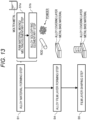
- FIG. 13 is a process chart showing an example of a method for manufacturing the wear-resistant member (in a case where a covering layer including the Cr-based alloy material is formed on a metal base material) according to the present invention. In order to avoid duplication of description, only portions different from the steps described in FIG. 12 will be described.
- An alloy covering layer forming step S4 is a step of forming a Cr-based alloy material covering layer at a desired position on a metal base material using the Cr-based alloy material obtained in the alloy material forming step S1.
- the method for forming the alloy covering layer is not particularly limited as long as a desired Cr-based alloy material covering layer can be formed, but for example, a buildup welding method or a thermal spraying method can be preferably used.
- the buildup welding method is not particularly limited, and it is possible to appropriately use conventional methods (e.g., a shielded arc welding method, a CO 2 welding method, a metal active gas (MAG) welding method, a metal inert gas (MIG) welding method, a tungsten inert gas (TIG) welding method, a submerged arc welding method, and a plasma transferred arc (PTA) welding method).
- a shielded arc welding method e.g., a CO 2 welding method, a metal active gas (MAG) welding method, a metal inert gas (MIG) welding method, a tungsten inert gas (TIG) welding method, a submerged arc welding method, and a plasma transferred arc (PTA) welding method.
- the thermal spraying method is not particularly limited, and it is possible to appropriately use conventional methods (e.g., a flame spraying method, a high-speed flame spraying method, an arc spraying method, a plasma spraying method,
- the material of the metal base material is not particularly limited, but a steel material can be preferably used from the viewpoint of mechanical strength and cost required for the final wear-resistant member.
- a steel material can be preferably used from the viewpoint of mechanical strength and cost required for the final wear-resistant member.
- an Ni-based alloy material may be used as the material of the metal base material.
- the thickness of the covering layer is also not particularly limited, and may be appropriately selected according to the application of the final wear-resistant member. For example, the thickness is preferably in a range of 2 mm or more and 20 mm or less.
- an alloy covering layer shaping step S5 of subjecting the Cr-based alloy covering layer formed in the alloy covering layer forming step S4 to final shaping is performed.
- the shaping method is not particularly limited, and it is possible to appropriately use conventional methods (e.g., cutting, grinding, and polishing).
- the alloy covering layer shaping step is not an essential step, but is preferably performed from the viewpoint of the shape and dimension accuracy required for the final wear-resistant member.
- Raw materials were mixed and melted by radio frequency melting (at a melting temperature of 1500°C or higher in a reduced-pressure Ar atmosphere) to form molten metals with each nominal alloy composition shown in Table 1, and then the molten metals each were subjected to a metal mold casting method using a copper mold to produce cylindrical molded bodies (20 mm in diameter and 50 mm in length).
- A-1 and A-2 are Co-based alloy materials that have a composition satisfying the alloy composition of the present invention
- A-3 is a Co-based alloy material (not containing the Ti component) that has a composition deviating from the alloy composition of the present invention
- A-4 and A-5 are commercially available Co-based alloy materials.
- Table 1 the content rate (unit: mass%) of each component is converted so that the sum of the described components is 100 mass%.
- the total content of impurities (N, O, P, and S) was confirmed to be 0.1 mass% or less and included in the content rate of the main components.
- Plate materials (15 mm ⁇ 20 mm ⁇ 2 mm) were cut out from the cylindrical molded body prepared above, and subjected to surface polishing to produce test evaluation samples of Examples 1 and 2 and Comparative Examples 1 to 3.
- FIG. 14 shows SEM observation images showing an example of a cross-sectional microstructure in the test evaluation sample of Example 2, and the images are a reflected electron image, a ferrite phase map, an Nb carbide phase map, and an austenite phase map, respectively.
- FIG. 1 described above shows the test evaluation sample of Example 1.
- the parent phase includes a mixed phase of a ferrite phase ( ⁇ phase) and an austenite phase ( ⁇ phase), and the Nb carbide phase is dispersed and precipitated in the parent phase.
- the Nb carbide phase is mainly precipitated in a dendritic/leaf vein form, and is precipitated in a granular form in some places.
- the ferrite phase has an area percentage of 77.4%
- the austenite phase has an area percentage of 10.5%
- the Nb carbide phase has an area percentage of 12.0%.
- the content rate of the Nb in Example 2 is higher than the content rate of the Nb in Example 1, and thus the ratio of the Nb carbide phase is high.
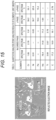
- FIG. 15 shows a magnified view of reflected electron image and analysis results of elements of the test evaluation sample of Example 2.
- the granular Nb carbide phase has an average particle size of 10 ⁇ m or less.
- the Ti component is not detected from the parent phase ( ⁇ and ⁇ phases), but is detected only from the Nb carbide phase, and it is strongly suggested that the Ti component is a starting point (species) for precipitation of the Nb carbide phase.
- the Nb component was not contained in the Co-based alloy material of the test evaluation samples of Comparative Examples 2 and 3, and thus the Nb carbide phase was not formed and precipitated, and instead, the Cr carbide phase was confirmed to be precipitated.
- a friction-wear test (using a reciprocating friction wear tester: ⁇ -100N, manufactured by Takachiho-Seiki. Co., Ltd.) for bringing test evaluation samples into contact with each other and allowing the samples to slide back and forth was performed to measure the friction coefficients.
- the measurement conditions were as follows: a surface pressure of 9.9 MPa and a slide stroke of 15 mm. Further, the number of cracks (cracks having a length of more than 5 ⁇ m) in the wear track (in the range of 1 cm in the direction orthogonal to the sliding direction) after the friction-wear test was examined using SEM.
- Examples 1 and 2 are determined as “excellent”
- Comparative Example 1 is determined as “acceptable”
- Comparative Examples 2 and 3 are determined as “unacceptable”.
- a small fluctuation range of the friction coefficient means that the change in the surface state of the friction sliding surface is small.
- Examples 1 and 2 have friction coefficients smaller than friction coefficients of Comparative Examples 2 and 3. The small friction coefficient leads to a reduction in friction loss during operation in the mechanical device using the member.
- the specific gravity of the Nb carbide phase particles decreased due to an increase in the content rate of the Ti in the Nb carbide phase particles, and thus the Nb carbide phase particles were floated (were pushed to the final solidified region) during solidification of the parent phase.
- Such a structure form is not preferred because when the surface of the cast body is ground to finish the surface of the wear-resistant member, the Nb carbide phase particles in the vicinity of the surface are scraped off, thereby making it difficult to control the amount of the Nb carbide phases precipitated on the surface of the final wear-resistant member (i.e., an inner region of the cast body).
Landscapes
- Chemical & Material Sciences (AREA)
- Engineering & Computer Science (AREA)
- Mechanical Engineering (AREA)
- Materials Engineering (AREA)
- Metallurgy (AREA)
- Organic Chemistry (AREA)
- Chemical Kinetics & Catalysis (AREA)
- Physics & Mathematics (AREA)
- Plasma & Fusion (AREA)
- Powder Metallurgy (AREA)
Claims (10)
- Verschleißfestes Element, das ein Legierungsmaterial auf Cr-Basis umfasst, wobei
das Legierungsmaterial auf Cr-Basis eine Legierungszusammensetzung aufweist, die aus Folgendem besteht:mehr als 40 Massen-% und 65 Massen-% oder weniger an Cr;15 Massen-% oder mehr und 40 Massen-% oder weniger an Ni;mehr als 0 Massen-% und 30 Massen-% oder weniger an Fe;5 Massen-% oder mehr und 16 Massen-% oder weniger an Nb;0,1 Massen-% oder mehr und 0,9 Massen-% oder weniger an Ti;0,6 Massen-% oder mehr und 2,5 Massen-% oder weniger an C;2 Massen-% oder weniger Mn;gegebenenfalls zumindest eines aus: 0,1 Massen-% oder mehr und 5 Massen-% oder weniger an Cu, 0,1 Massen-% oder mehr und 1 Massen-% oder weniger an Si, 0,02 Massen-% oder mehr und 0,3 Massen-% oder weniger an Sn und 0,005 Massen-% oder mehr und 0,05 Massen-% oder weniger an Al;
undinsgesamt 1 Massen-% oder weniger Verunreinigungen, einschließlich von 0,04 Massen-% oder weniger an N, 0,02 Massen-% oder weniger an O, 0,04 Massen-% oder weniger an P, 0,005 Massen-% oder weniger an S und 0,2 Massen-% oder weniger an Ta;wobei das Massenverhältnis Ti/Nb zwischen Nb und Ti 0,063 oder weniger beträgt. - Verschleißfestes Element nach Anspruch 1, wobei das Legierungsmaterial auf Cr-Basis eine Ferrit-Phase als Hauptphase umfasst und eine Nb-Carbid-Phase mit einer dendritischen und granulären Form in einem Gesamt-Flächenprozentanteil von 4 % oder mehr und 30 % oder weniger ausgefällt ist.
- Verschleißfestes Element nach Anspruch 1 oder 2, wobei in der Legierungszusammensetzung der Gehaltsanteil an Ni höher ist als der Gehaltsanteil an Fe und das Massenverhältnis C/Nb zwischen Nb und C 0,11 oder mehr und 0,16 oder weniger beträgt und das Massenverhältnis Ti/Nb 0,0062 oder mehr beträgt.
- Verschleißfestes Element nach einem der Ansprüche 1 bis 3, wobei das verschleißfeste Element vollständig aus dem Legierungsmaterial auf Cr-Basis besteht.
- Verschleißfestes Element nach einem der Ansprüche 1 bis 3, wobei das verschleißfeste Element durch Ausbilden einer Deckschicht, die das Legierungsmaterial auf Cr-Basis umfasst, auf einem Metall-Basismaterial und einer Oberflächenschicht-Region der Deckschicht, welche die Legierungszusammensetzung aufweist, erhalten wird.
- Verschleißfestes Element nach Anspruch 5, wobei die Deckschicht eine Dicke von 2 mm oder mehr und 20 mm oder weniger aufweist.
- Verschleißfestes Element nach Anspruch 5 oder 6, wobei die Deckschicht eine aufbaugeschweißte Schicht ist.
- Verschleißfestes Element nach einem der Ansprüche 5 bis 7, wobei das Metall-Basismaterial aus einem Stahlmaterial besteht.
- Verschleißfestes Element nach einem der Ansprüche 1 bis 8, wobei das verschleißfeste Element ein Gleitelement, ein Walzelement oder ein Ventilelement ist.
- Mechanische Vorrichtung, die Folgendes umfasst:ein Gleitelement,ein Walzelement oderein Ventilelement;wobei das Gleitelement, das Walzelement oder das Ventilelement ein verschleißfestes Element nach einem der Ansprüche 1 bis 8 ist.
Applications Claiming Priority (3)
| Application Number | Priority Date | Filing Date | Title |
|---|---|---|---|
| JP2020100223A JP7612347B2 (ja) | 2020-06-09 | 2020-06-09 | 耐摩耗性部材およびそれを用いた機械装置 |
| JP2020100224A JP7545820B2 (ja) | 2020-06-09 | 2020-06-09 | 耐摩耗性部材およびそれを用いた機械装置 |
| PCT/JP2021/021882 WO2021251423A1 (ja) | 2020-06-09 | 2021-06-09 | 耐摩耗性部材およびそれを用いた機械装置 |
Publications (3)
| Publication Number | Publication Date |
|---|---|
| EP4163409A1 EP4163409A1 (de) | 2023-04-12 |
| EP4163409A4 EP4163409A4 (de) | 2024-07-31 |
| EP4163409B1 true EP4163409B1 (de) | 2025-03-26 |
Family
ID=78846053
Family Applications (1)
| Application Number | Title | Priority Date | Filing Date |
|---|---|---|---|
| EP21822810.4A Active EP4163409B1 (de) | 2020-06-09 | 2021-06-09 | Verschleissfestes element |
Country Status (3)
| Country | Link |
|---|---|
| US (1) | US12312659B2 (de) |
| EP (1) | EP4163409B1 (de) |
| WO (1) | WO2021251423A1 (de) |
Families Citing this family (2)
| Publication number | Priority date | Publication date | Assignee | Title |
|---|---|---|---|---|
| JP7665324B2 (ja) * | 2020-12-11 | 2025-04-21 | 株式会社日立製作所 | 耐摩耗性部材およびそれを用いた機械装置 |
| CN116117383B (zh) * | 2023-04-07 | 2023-08-18 | 西安热工研究院有限公司 | 高硬耐蚀金属基陶瓷复合焊丝及其制备方法 |
Family Cites Families (12)
| Publication number | Priority date | Publication date | Assignee | Title |
|---|---|---|---|---|
| JPS582259B2 (ja) * | 1976-12-24 | 1983-01-14 | 三菱マテリアル株式会社 | 硝酸および弗酸よりなる混酸に対してすぐれた耐食性を示す高クロム合金 |
| JPH04358054A (ja) * | 1991-06-03 | 1992-12-11 | Kobe Steel Ltd | 耐エロージョン性に優れた溶射用粉末材料および表面 被覆部品 |
| JP3148340B2 (ja) | 1991-08-27 | 2001-03-19 | 福田金属箔粉工業株式会社 | ハードフェーシング用高靱性クロム基合金、その粉末、および該合金を肉盛した自動車用エンジンバルブ |
| DE19508069C1 (de) * | 1995-02-27 | 1996-05-23 | Nu Tech Gmbh | Auslaßventil für eine Diesel-Hubkolben-Brennkraftmaschine |
| JP4978790B2 (ja) | 2007-08-27 | 2012-07-18 | 三菱マテリアル株式会社 | 樹脂成形用金型部材 |
| CN101592186B (zh) * | 2009-07-10 | 2011-01-26 | 攀钢集团钢铁钒钛股份有限公司 | 轴瓦轴套 |
| KR101563533B1 (ko) * | 2012-10-31 | 2015-10-27 | 후쿠다 킨조쿠 하쿠훈 코교 가부시키가이샤 | 내고온 부식 특성을 구비한 Ni-Cr-Co계 합금과 그것을 사용해서 표면 개질된 포핏밸브 |
| JP5947342B2 (ja) * | 2014-07-30 | 2016-07-06 | 岡野バルブ製造株式会社 | 原子力発電プラント用弁装置 |
| WO2017168972A1 (ja) * | 2016-03-30 | 2017-10-05 | 株式会社日立製作所 | クロム基二相合金および該二相合金を用いた製造物 |
| WO2017169056A1 (ja) * | 2016-03-30 | 2017-10-05 | 株式会社日立製作所 | Cr基二相合金及びその製造物 |
| WO2019189531A1 (ja) * | 2018-03-28 | 2019-10-03 | 日立金属株式会社 | Cr-Ni系合金、Cr-Ni系合金でなる急冷凝固成形体、合金粉末、粉末冶金成形体、鋳造成形体、Cr-Ni系合金の製造方法およびCr-Ni系合金を用いた機械設備、配管部材 |
| JP7459787B2 (ja) * | 2018-03-28 | 2024-04-02 | 株式会社プロテリアル | 耐摩耗性部品 |
-
2021
- 2021-06-09 EP EP21822810.4A patent/EP4163409B1/de active Active
- 2021-06-09 US US18/009,211 patent/US12312659B2/en active Active
- 2021-06-09 WO PCT/JP2021/021882 patent/WO2021251423A1/ja not_active Ceased
Also Published As
| Publication number | Publication date |
|---|---|
| US20230304132A1 (en) | 2023-09-28 |
| EP4163409A1 (de) | 2023-04-12 |
| US12312659B2 (en) | 2025-05-27 |
| EP4163409A4 (de) | 2024-07-31 |
| WO2021251423A1 (ja) | 2021-12-16 |
Similar Documents
| Publication | Publication Date | Title |
|---|---|---|
| EP3372699B1 (de) | Gleitelement | |
| US12351894B2 (en) | Powder made of a cobalt-chromium alloy | |
| EP3814543B1 (de) | Aufschweisslegierung auf kupferbasis | |
| US11732331B2 (en) | Ni-based alloy, and Ni-based alloy product and methods for producing the same | |
| KR20190046768A (ko) | 플라스틱 성형 공구에 적합한 강재 | |
| EP3936259A1 (de) | Legierungselement auf ni-basis mit einem generativ gefertigten gegenstand, verfahren zur herstellung von legierungselementen auf ni-basis und produkt unter verwendung von ni-basislegierung | |
| EP3483295B1 (de) | Reparaturschweissmaterial für matrize | |
| EP3467128B9 (de) | Extruderdüse aus warmarbeitsstahl und herstellungsverfahren dafür | |
| EP4163409B1 (de) | Verschleissfestes element | |
| CN113396233A (zh) | 具有改进的可压缩性和生坯强度的硬质粉末颗粒 | |
| EP2253727B1 (de) | Pulver für sinterlegierung auf eisenbasis | |
| EP3296418B1 (de) | Herstellungsverfahren für verschleissfeste gesinterte legierung auf eisenbasis sowie verschleissfeste gesinterte legierung auf eisenbasis | |
| JP7612347B2 (ja) | 耐摩耗性部材およびそれを用いた機械装置 | |
| JP7665324B2 (ja) | 耐摩耗性部材およびそれを用いた機械装置 | |
| EP1582603B1 (de) | Sinterlegierung auf eisenbasis, element aus sinterlegierung auf eisenbasis, herstellungsverfahren dafür und ölpumpenrotor | |
| EP4159883B1 (de) | Legierung auf fe-basis, metallpulver und deren verwendung für die schmelzverfestigungsformung | |
| JP7660623B2 (ja) | 内燃機関用鉄基焼結合金製バルブシート | |
| JPH07233401A (ja) | 切削性および寸法精度に優れたアトマイズ鋼粉および焼結鋼 | |
| EP0357216A1 (de) | Legierung zum Aufpanzern von Ventilen | |
| JP7545820B2 (ja) | 耐摩耗性部材およびそれを用いた機械装置 | |
| JP7302152B2 (ja) | Cr-Fe-Ni系合金製造物及びその製造方法 | |
| JP4303172B2 (ja) | 鉄基焼結合金製バルブシート | |
| EP4567144A1 (de) | Fe-cr-al-basiertes legierungspulver zur generativen fertigung, fe-cr-al-basiertes legierungselement und verfahren zur herstellung eines fe-cr-al-basierten legierungselements | |
| JP7648553B2 (ja) | 原子炉機器用の合金材料および該合金材料を用いた流路部材 | |
| TWI784294B (zh) | 複合陶瓷強化材料 |
Legal Events
| Date | Code | Title | Description |
|---|---|---|---|
| STAA | Information on the status of an ep patent application or granted ep patent |
Free format text: STATUS: THE INTERNATIONAL PUBLICATION HAS BEEN MADE |
|
| PUAI | Public reference made under article 153(3) epc to a published international application that has entered the european phase |
Free format text: ORIGINAL CODE: 0009012 |
|
| STAA | Information on the status of an ep patent application or granted ep patent |
Free format text: STATUS: REQUEST FOR EXAMINATION WAS MADE |
|
| 17P | Request for examination filed |
Effective date: 20221208 |
|
| AK | Designated contracting states |
Kind code of ref document: A1 Designated state(s): AL AT BE BG CH CY CZ DE DK EE ES FI FR GB GR HR HU IE IS IT LI LT LU LV MC MK MT NL NO PL PT RO RS SE SI SK SM TR |
|
| DAV | Request for validation of the european patent (deleted) | ||
| DAX | Request for extension of the european patent (deleted) | ||
| A4 | Supplementary search report drawn up and despatched |
Effective date: 20240702 |
|
| RIC1 | Information provided on ipc code assigned before grant |
Ipc: C23C 30/00 20060101ALI20240626BHEP Ipc: C23C 4/134 20160101ALI20240626BHEP Ipc: C23C 4/123 20160101ALI20240626BHEP Ipc: C23C 4/08 20160101ALI20240626BHEP Ipc: C23C 4/06 20160101ALI20240626BHEP Ipc: B23K 35/30 20060101ALI20240626BHEP Ipc: C22C 27/06 20060101AFI20240626BHEP |
|
| GRAP | Despatch of communication of intention to grant a patent |
Free format text: ORIGINAL CODE: EPIDOSNIGR1 |
|
| STAA | Information on the status of an ep patent application or granted ep patent |
Free format text: STATUS: GRANT OF PATENT IS INTENDED |
|
| INTG | Intention to grant announced |
Effective date: 20241028 |
|
| GRAS | Grant fee paid |
Free format text: ORIGINAL CODE: EPIDOSNIGR3 |
|
| GRAA | (expected) grant |
Free format text: ORIGINAL CODE: 0009210 |
|
| STAA | Information on the status of an ep patent application or granted ep patent |
Free format text: STATUS: THE PATENT HAS BEEN GRANTED |
|
| AK | Designated contracting states |
Kind code of ref document: B1 Designated state(s): AL AT BE BG CH CY CZ DE DK EE ES FI FR GB GR HR HU IE IS IT LI LT LU LV MC MK MT NL NO PL PT RO RS SE SI SK SM TR |
|
| REG | Reference to a national code |
Ref country code: GB Ref legal event code: FG4D |
|
| REG | Reference to a national code |
Ref country code: CH Ref legal event code: EP |
|
| REG | Reference to a national code |
Ref country code: DE Ref legal event code: R096 Ref document number: 602021028239 Country of ref document: DE |
|
| REG | Reference to a national code |
Ref country code: IE Ref legal event code: FG4D |
|
| PG25 | Lapsed in a contracting state [announced via postgrant information from national office to epo] |
Ref country code: RS Free format text: LAPSE BECAUSE OF FAILURE TO SUBMIT A TRANSLATION OF THE DESCRIPTION OR TO PAY THE FEE WITHIN THE PRESCRIBED TIME-LIMIT Effective date: 20250626 |
|
| PG25 | Lapsed in a contracting state [announced via postgrant information from national office to epo] |
Ref country code: FI Free format text: LAPSE BECAUSE OF FAILURE TO SUBMIT A TRANSLATION OF THE DESCRIPTION OR TO PAY THE FEE WITHIN THE PRESCRIBED TIME-LIMIT Effective date: 20250326 |
|
| REG | Reference to a national code |
Ref country code: LT Ref legal event code: MG9D |
|
| PG25 | Lapsed in a contracting state [announced via postgrant information from national office to epo] |
Ref country code: NO Free format text: LAPSE BECAUSE OF FAILURE TO SUBMIT A TRANSLATION OF THE DESCRIPTION OR TO PAY THE FEE WITHIN THE PRESCRIBED TIME-LIMIT Effective date: 20250626 |
|
| PG25 | Lapsed in a contracting state [announced via postgrant information from national office to epo] |
Ref country code: HR Free format text: LAPSE BECAUSE OF FAILURE TO SUBMIT A TRANSLATION OF THE DESCRIPTION OR TO PAY THE FEE WITHIN THE PRESCRIBED TIME-LIMIT Effective date: 20250326 |
|
| PG25 | Lapsed in a contracting state [announced via postgrant information from national office to epo] |
Ref country code: LV Free format text: LAPSE BECAUSE OF FAILURE TO SUBMIT A TRANSLATION OF THE DESCRIPTION OR TO PAY THE FEE WITHIN THE PRESCRIBED TIME-LIMIT Effective date: 20250326 |
|
| PGFP | Annual fee paid to national office [announced via postgrant information from national office to epo] |
Ref country code: FR Payment date: 20250620 Year of fee payment: 5 |
|
| PG25 | Lapsed in a contracting state [announced via postgrant information from national office to epo] |
Ref country code: GR Free format text: LAPSE BECAUSE OF FAILURE TO SUBMIT A TRANSLATION OF THE DESCRIPTION OR TO PAY THE FEE WITHIN THE PRESCRIBED TIME-LIMIT Effective date: 20250627 Ref country code: BG Free format text: LAPSE BECAUSE OF FAILURE TO SUBMIT A TRANSLATION OF THE DESCRIPTION OR TO PAY THE FEE WITHIN THE PRESCRIBED TIME-LIMIT Effective date: 20250326 |
|
| PGFP | Annual fee paid to national office [announced via postgrant information from national office to epo] |
Ref country code: AT Payment date: 20250721 Year of fee payment: 5 |
|
| REG | Reference to a national code |
Ref country code: NL Ref legal event code: MP Effective date: 20250326 |
|
| PG25 | Lapsed in a contracting state [announced via postgrant information from national office to epo] |
Ref country code: NL Free format text: LAPSE BECAUSE OF FAILURE TO SUBMIT A TRANSLATION OF THE DESCRIPTION OR TO PAY THE FEE WITHIN THE PRESCRIBED TIME-LIMIT Effective date: 20250326 |
|
| PG25 | Lapsed in a contracting state [announced via postgrant information from national office to epo] |
Ref country code: SE Free format text: LAPSE BECAUSE OF FAILURE TO SUBMIT A TRANSLATION OF THE DESCRIPTION OR TO PAY THE FEE WITHIN THE PRESCRIBED TIME-LIMIT Effective date: 20250326 |
|
| REG | Reference to a national code |
Ref country code: AT Ref legal event code: MK05 Ref document number: 1779048 Country of ref document: AT Kind code of ref document: T Effective date: 20250326 |
|
| PG25 | Lapsed in a contracting state [announced via postgrant information from national office to epo] |
Ref country code: SM Free format text: LAPSE BECAUSE OF FAILURE TO SUBMIT A TRANSLATION OF THE DESCRIPTION OR TO PAY THE FEE WITHIN THE PRESCRIBED TIME-LIMIT Effective date: 20250326 |
|
| PG25 | Lapsed in a contracting state [announced via postgrant information from national office to epo] |
Ref country code: ES Free format text: LAPSE BECAUSE OF FAILURE TO SUBMIT A TRANSLATION OF THE DESCRIPTION OR TO PAY THE FEE WITHIN THE PRESCRIBED TIME-LIMIT Effective date: 20250326 Ref country code: PT Free format text: LAPSE BECAUSE OF FAILURE TO SUBMIT A TRANSLATION OF THE DESCRIPTION OR TO PAY THE FEE WITHIN THE PRESCRIBED TIME-LIMIT Effective date: 20250728 |
|
| PG25 | Lapsed in a contracting state [announced via postgrant information from national office to epo] |
Ref country code: IT Free format text: LAPSE BECAUSE OF FAILURE TO SUBMIT A TRANSLATION OF THE DESCRIPTION OR TO PAY THE FEE WITHIN THE PRESCRIBED TIME-LIMIT Effective date: 20250326 Ref country code: PL Free format text: LAPSE BECAUSE OF FAILURE TO SUBMIT A TRANSLATION OF THE DESCRIPTION OR TO PAY THE FEE WITHIN THE PRESCRIBED TIME-LIMIT Effective date: 20250326 |
|
| PG25 | Lapsed in a contracting state [announced via postgrant information from national office to epo] |
Ref country code: AT Free format text: LAPSE BECAUSE OF FAILURE TO SUBMIT A TRANSLATION OF THE DESCRIPTION OR TO PAY THE FEE WITHIN THE PRESCRIBED TIME-LIMIT Effective date: 20250326 |
|
| PG25 | Lapsed in a contracting state [announced via postgrant information from national office to epo] |
Ref country code: EE Free format text: LAPSE BECAUSE OF FAILURE TO SUBMIT A TRANSLATION OF THE DESCRIPTION OR TO PAY THE FEE WITHIN THE PRESCRIBED TIME-LIMIT Effective date: 20250326 |
|
| PG25 | Lapsed in a contracting state [announced via postgrant information from national office to epo] |
Ref country code: RO Free format text: LAPSE BECAUSE OF FAILURE TO SUBMIT A TRANSLATION OF THE DESCRIPTION OR TO PAY THE FEE WITHIN THE PRESCRIBED TIME-LIMIT Effective date: 20250326 |
|
| PG25 | Lapsed in a contracting state [announced via postgrant information from national office to epo] |
Ref country code: SK Free format text: LAPSE BECAUSE OF FAILURE TO SUBMIT A TRANSLATION OF THE DESCRIPTION OR TO PAY THE FEE WITHIN THE PRESCRIBED TIME-LIMIT Effective date: 20250326 |
|
| PG25 | Lapsed in a contracting state [announced via postgrant information from national office to epo] |
Ref country code: IS Free format text: LAPSE BECAUSE OF FAILURE TO SUBMIT A TRANSLATION OF THE DESCRIPTION OR TO PAY THE FEE WITHIN THE PRESCRIBED TIME-LIMIT Effective date: 20250726 |
|
| REG | Reference to a national code |
Ref country code: DE Ref legal event code: R119 Ref document number: 602021028239 Country of ref document: DE |
|
| PG25 | Lapsed in a contracting state [announced via postgrant information from national office to epo] |
Ref country code: DK Free format text: LAPSE BECAUSE OF FAILURE TO SUBMIT A TRANSLATION OF THE DESCRIPTION OR TO PAY THE FEE WITHIN THE PRESCRIBED TIME-LIMIT Effective date: 20250326 |
|
| PG25 | Lapsed in a contracting state [announced via postgrant information from national office to epo] |
Ref country code: CZ Free format text: LAPSE BECAUSE OF FAILURE TO SUBMIT A TRANSLATION OF THE DESCRIPTION OR TO PAY THE FEE WITHIN THE PRESCRIBED TIME-LIMIT Effective date: 20250326 |
|
| REG | Reference to a national code |
Ref country code: CH Ref legal event code: H13 Free format text: ST27 STATUS EVENT CODE: U-0-0-H10-H13 (AS PROVIDED BY THE NATIONAL OFFICE) Effective date: 20260127 |
|
| PG25 | Lapsed in a contracting state [announced via postgrant information from national office to epo] |
Ref country code: MC Free format text: LAPSE BECAUSE OF FAILURE TO SUBMIT A TRANSLATION OF THE DESCRIPTION OR TO PAY THE FEE WITHIN THE PRESCRIBED TIME-LIMIT Effective date: 20250326 |
|
| PLBE | No opposition filed within time limit |
Free format text: ORIGINAL CODE: 0009261 |
|
| STAA | Information on the status of an ep patent application or granted ep patent |
Free format text: STATUS: NO OPPOSITION FILED WITHIN TIME LIMIT |
|
| REG | Reference to a national code |
Ref country code: CH Ref legal event code: L10 Free format text: ST27 STATUS EVENT CODE: U-0-0-L10-L00 (AS PROVIDED BY THE NATIONAL OFFICE) Effective date: 20260211 |
|
| PG25 | Lapsed in a contracting state [announced via postgrant information from national office to epo] |
Ref country code: LU Free format text: LAPSE BECAUSE OF NON-PAYMENT OF DUE FEES Effective date: 20250609 |
|
| GBPC | Gb: european patent ceased through non-payment of renewal fee |
Effective date: 20250626 |
|
| REG | Reference to a national code |
Ref country code: BE Ref legal event code: MM Effective date: 20250630 |
|
| 26N | No opposition filed |
Effective date: 20260105 |
|
| PG25 | Lapsed in a contracting state [announced via postgrant information from national office to epo] |
Ref country code: GB Free format text: LAPSE BECAUSE OF NON-PAYMENT OF DUE FEES Effective date: 20250626 |
|
| PG25 | Lapsed in a contracting state [announced via postgrant information from national office to epo] |
Ref country code: DE Free format text: LAPSE BECAUSE OF NON-PAYMENT OF DUE FEES Effective date: 20260101 Ref country code: IE Free format text: LAPSE BECAUSE OF NON-PAYMENT OF DUE FEES Effective date: 20250609 |
|
| PG25 | Lapsed in a contracting state [announced via postgrant information from national office to epo] |
Ref country code: BE Free format text: LAPSE BECAUSE OF NON-PAYMENT OF DUE FEES Effective date: 20250630 |