EP4163025A1 - Dispositif et procédé de décomposition de matières composites et de leurs mélanges en composants de matières séparés - Google Patents
Dispositif et procédé de décomposition de matières composites et de leurs mélanges en composants de matières séparés Download PDFInfo
- Publication number
- EP4163025A1 EP4163025A1 EP21306396.9A EP21306396A EP4163025A1 EP 4163025 A1 EP4163025 A1 EP 4163025A1 EP 21306396 A EP21306396 A EP 21306396A EP 4163025 A1 EP4163025 A1 EP 4163025A1
- Authority
- EP
- European Patent Office
- Prior art keywords
- material flow
- reactor
- discharged
- rotor
- composite materials
- Prior art date
- Legal status (The legal status is an assumption and is not a legal conclusion. Google has not performed a legal analysis and makes no representation as to the accuracy of the status listed.)
- Pending
Links
- 239000000463 material Substances 0.000 title claims abstract description 164
- 239000002131 composite material Substances 0.000 title claims abstract description 65
- 239000000203 mixture Substances 0.000 title claims abstract description 43
- 238000000034 method Methods 0.000 title claims abstract description 40
- 239000012530 fluid Substances 0.000 claims abstract description 36
- 239000007788 liquid Substances 0.000 claims abstract description 28
- 239000002245 particle Substances 0.000 claims description 26
- XLYOFNOQVPJJNP-UHFFFAOYSA-N water Substances O XLYOFNOQVPJJNP-UHFFFAOYSA-N 0.000 claims description 26
- 238000000926 separation method Methods 0.000 claims description 20
- 229910052751 metal Inorganic materials 0.000 claims description 12
- 239000002184 metal Substances 0.000 claims description 12
- 239000004033 plastic Substances 0.000 claims description 12
- 229920003023 plastic Polymers 0.000 claims description 12
- 229910052782 aluminium Inorganic materials 0.000 claims description 11
- XAGFODPZIPBFFR-UHFFFAOYSA-N aluminium Chemical compound [Al] XAGFODPZIPBFFR-UHFFFAOYSA-N 0.000 claims description 11
- 239000012080 ambient air Substances 0.000 claims description 10
- RYGMFSIKBFXOCR-UHFFFAOYSA-N Copper Chemical compound [Cu] RYGMFSIKBFXOCR-UHFFFAOYSA-N 0.000 claims description 9
- 239000000725 suspension Substances 0.000 claims description 9
- 239000010949 copper Substances 0.000 claims description 8
- 229910052802 copper Inorganic materials 0.000 claims description 8
- 230000029087 digestion Effects 0.000 claims description 8
- 150000002739 metals Chemical class 0.000 claims description 8
- 239000007787 solid Substances 0.000 claims description 8
- 238000005188 flotation Methods 0.000 claims description 6
- 239000012634 fragment Substances 0.000 claims description 6
- 239000003570 air Substances 0.000 claims description 5
- 230000001143 conditioned effect Effects 0.000 claims description 5
- 239000010970 precious metal Substances 0.000 claims description 5
- 230000006698 induction Effects 0.000 claims description 4
- 229910052761 rare earth metal Inorganic materials 0.000 claims description 4
- 150000002910 rare earth metals Chemical class 0.000 claims description 4
- 238000002156 mixing Methods 0.000 claims description 3
- 239000013049 sediment Substances 0.000 claims description 3
- 229910000881 Cu alloy Inorganic materials 0.000 claims description 2
- 230000005284 excitation Effects 0.000 claims description 2
- 230000037230 mobility Effects 0.000 claims 3
- 238000011144 upstream manufacturing Methods 0.000 claims 2
- 238000000354 decomposition reaction Methods 0.000 claims 1
- 238000007599 discharging Methods 0.000 claims 1
- 230000017525 heat dissipation Effects 0.000 claims 1
- 230000003993 interaction Effects 0.000 claims 1
- 230000009471 action Effects 0.000 abstract description 3
- 239000007789 gas Substances 0.000 description 12
- 230000008569 process Effects 0.000 description 11
- 239000000126 substance Substances 0.000 description 8
- 239000002699 waste material Substances 0.000 description 8
- 230000000694 effects Effects 0.000 description 7
- 238000004519 manufacturing process Methods 0.000 description 7
- XKRFYHLGVUSROY-UHFFFAOYSA-N Argon Chemical compound [Ar] XKRFYHLGVUSROY-UHFFFAOYSA-N 0.000 description 6
- IJGRMHOSHXDMSA-UHFFFAOYSA-N Atomic nitrogen Chemical compound N#N IJGRMHOSHXDMSA-UHFFFAOYSA-N 0.000 description 6
- 230000015556 catabolic process Effects 0.000 description 6
- 239000002994 raw material Substances 0.000 description 5
- 230000001133 acceleration Effects 0.000 description 4
- 230000008901 benefit Effects 0.000 description 4
- 238000010276 construction Methods 0.000 description 4
- 239000010792 electronic scrap Substances 0.000 description 4
- 230000005484 gravity Effects 0.000 description 4
- 229910052500 inorganic mineral Inorganic materials 0.000 description 4
- 239000011707 mineral Substances 0.000 description 4
- 238000004064 recycling Methods 0.000 description 4
- 238000010521 absorption reaction Methods 0.000 description 3
- 229910052786 argon Inorganic materials 0.000 description 3
- 238000010586 diagram Methods 0.000 description 3
- 238000009826 distribution Methods 0.000 description 3
- 239000011152 fibreglass Substances 0.000 description 3
- 229910052757 nitrogen Inorganic materials 0.000 description 3
- 238000004806 packaging method and process Methods 0.000 description 3
- 239000004593 Epoxy Substances 0.000 description 2
- 239000004411 aluminium Substances 0.000 description 2
- 230000008859 change Effects 0.000 description 2
- 230000000739 chaotic effect Effects 0.000 description 2
- -1 copper Chemical class 0.000 description 2
- 239000000428 dust Substances 0.000 description 2
- 238000003912 environmental pollution Methods 0.000 description 2
- 239000003822 epoxy resin Substances 0.000 description 2
- 239000002923 metal particle Substances 0.000 description 2
- 239000003921 oil Substances 0.000 description 2
- 230000000704 physical effect Effects 0.000 description 2
- 229920000647 polyepoxide Polymers 0.000 description 2
- 238000010298 pulverizing process Methods 0.000 description 2
- 238000012216 screening Methods 0.000 description 2
- FIKFLLIUPUVONI-UHFFFAOYSA-N 8-(2-phenylethyl)-1-oxa-3,8-diazaspiro[4.5]decan-2-one;hydrochloride Chemical compound Cl.O1C(=O)NCC11CCN(CCC=2C=CC=CC=2)CC1 FIKFLLIUPUVONI-UHFFFAOYSA-N 0.000 description 1
- 229910000838 Al alloy Inorganic materials 0.000 description 1
- 235000008733 Citrus aurantifolia Nutrition 0.000 description 1
- 229910002549 Fe–Cu Inorganic materials 0.000 description 1
- WHXSMMKQMYFTQS-UHFFFAOYSA-N Lithium Chemical compound [Li] WHXSMMKQMYFTQS-UHFFFAOYSA-N 0.000 description 1
- 238000003723 Smelting Methods 0.000 description 1
- 229910000831 Steel Inorganic materials 0.000 description 1
- 235000011941 Tilia x europaea Nutrition 0.000 description 1
- 239000000654 additive Substances 0.000 description 1
- 239000002671 adjuvant Substances 0.000 description 1
- 230000004888 barrier function Effects 0.000 description 1
- 230000015572 biosynthetic process Effects 0.000 description 1
- 238000005253 cladding Methods 0.000 description 1
- 239000011365 complex material Substances 0.000 description 1
- 150000001875 compounds Chemical class 0.000 description 1
- 239000004020 conductor Substances 0.000 description 1
- 239000011162 core material Substances 0.000 description 1
- 230000002354 daily effect Effects 0.000 description 1
- 230000032798 delamination Effects 0.000 description 1
- 238000009792 diffusion process Methods 0.000 description 1
- 239000010793 electronic waste Substances 0.000 description 1
- 238000007786 electrostatic charging Methods 0.000 description 1
- 238000005421 electrostatic potential Methods 0.000 description 1
- 230000007613 environmental effect Effects 0.000 description 1
- 230000003203 everyday effect Effects 0.000 description 1
- 238000000605 extraction Methods 0.000 description 1
- 230000005294 ferromagnetic effect Effects 0.000 description 1
- 239000010419 fine particle Substances 0.000 description 1
- 235000013312 flour Nutrition 0.000 description 1
- 239000011888 foil Substances 0.000 description 1
- 239000003365 glass fiber Substances 0.000 description 1
- PCHJSUWPFVWCPO-UHFFFAOYSA-N gold Chemical compound [Au] PCHJSUWPFVWCPO-UHFFFAOYSA-N 0.000 description 1
- 239000010931 gold Substances 0.000 description 1
- 229910052737 gold Inorganic materials 0.000 description 1
- LNEPOXFFQSENCJ-UHFFFAOYSA-N haloperidol Chemical compound C1CC(O)(C=2C=CC(Cl)=CC=2)CCN1CCCC(=O)C1=CC=C(F)C=C1 LNEPOXFFQSENCJ-UHFFFAOYSA-N 0.000 description 1
- 229910001385 heavy metal Inorganic materials 0.000 description 1
- 230000006872 improvement Effects 0.000 description 1
- 239000012212 insulator Substances 0.000 description 1
- 239000004571 lime Substances 0.000 description 1
- 229910052744 lithium Inorganic materials 0.000 description 1
- 238000011068 loading method Methods 0.000 description 1
- 230000005291 magnetic effect Effects 0.000 description 1
- 238000012423 maintenance Methods 0.000 description 1
- 230000003647 oxidation Effects 0.000 description 1
- 238000007254 oxidation reaction Methods 0.000 description 1
- 230000002093 peripheral effect Effects 0.000 description 1
- JTJMJGYZQZDUJJ-UHFFFAOYSA-N phencyclidine Chemical class C1CCCCN1C1(C=2C=CC=CC=2)CCCCC1 JTJMJGYZQZDUJJ-UHFFFAOYSA-N 0.000 description 1
- 208000026438 poor feeding Diseases 0.000 description 1
- 238000004537 pulping Methods 0.000 description 1
- 238000011084 recovery Methods 0.000 description 1
- 230000009467 reduction Effects 0.000 description 1
- 230000004044 response Effects 0.000 description 1
- 238000004062 sedimentation Methods 0.000 description 1
- 230000035939 shock Effects 0.000 description 1
- 239000002893 slag Substances 0.000 description 1
- 239000010802 sludge Substances 0.000 description 1
- 239000007858 starting material Substances 0.000 description 1
- 239000010959 steel Substances 0.000 description 1
- 238000007669 thermal treatment Methods 0.000 description 1
- 229920001169 thermoplastic Polymers 0.000 description 1
- 239000004416 thermosoftening plastic Substances 0.000 description 1
- 239000002351 wastewater Substances 0.000 description 1
- 238000007704 wet chemistry method Methods 0.000 description 1
- 239000002023 wood Substances 0.000 description 1
Images


Classifications
-
- B—PERFORMING OPERATIONS; TRANSPORTING
- B09—DISPOSAL OF SOLID WASTE; RECLAMATION OF CONTAMINATED SOIL
- B09B—DISPOSAL OF SOLID WASTE
- B09B3/00—Destroying solid waste or transforming solid waste into something useful or harmless
- B09B3/30—Destroying solid waste or transforming solid waste into something useful or harmless involving mechanical treatment
- B09B3/35—Shredding, crushing or cutting
-
- B—PERFORMING OPERATIONS; TRANSPORTING
- B02—CRUSHING, PULVERISING, OR DISINTEGRATING; PREPARATORY TREATMENT OF GRAIN FOR MILLING
- B02C—CRUSHING, PULVERISING, OR DISINTEGRATING IN GENERAL; MILLING GRAIN
- B02C13/00—Disintegrating by mills having rotary beater elements ; Hammer mills
- B02C13/14—Disintegrating by mills having rotary beater elements ; Hammer mills with vertical rotor shaft, e.g. combined with sifting devices
- B02C13/18—Disintegrating by mills having rotary beater elements ; Hammer mills with vertical rotor shaft, e.g. combined with sifting devices with beaters rigidly connected to the rotor
- B02C13/1807—Disintegrating by mills having rotary beater elements ; Hammer mills with vertical rotor shaft, e.g. combined with sifting devices with beaters rigidly connected to the rotor the material to be crushed being thrown against an anvil or impact plate
-
- B—PERFORMING OPERATIONS; TRANSPORTING
- B02—CRUSHING, PULVERISING, OR DISINTEGRATING; PREPARATORY TREATMENT OF GRAIN FOR MILLING
- B02C—CRUSHING, PULVERISING, OR DISINTEGRATING IN GENERAL; MILLING GRAIN
- B02C21/00—Disintegrating plant with or without drying of the material
-
- B—PERFORMING OPERATIONS; TRANSPORTING
- B02—CRUSHING, PULVERISING, OR DISINTEGRATING; PREPARATORY TREATMENT OF GRAIN FOR MILLING
- B02C—CRUSHING, PULVERISING, OR DISINTEGRATING IN GENERAL; MILLING GRAIN
- B02C23/00—Auxiliary methods or auxiliary devices or accessories specially adapted for crushing or disintegrating not provided for in preceding groups or not specially adapted to apparatus covered by a single preceding group
- B02C23/02—Feeding devices
-
- B—PERFORMING OPERATIONS; TRANSPORTING
- B02—CRUSHING, PULVERISING, OR DISINTEGRATING; PREPARATORY TREATMENT OF GRAIN FOR MILLING
- B02C—CRUSHING, PULVERISING, OR DISINTEGRATING IN GENERAL; MILLING GRAIN
- B02C23/00—Auxiliary methods or auxiliary devices or accessories specially adapted for crushing or disintegrating not provided for in preceding groups or not specially adapted to apparatus covered by a single preceding group
- B02C23/08—Separating or sorting of material, associated with crushing or disintegrating
-
- B—PERFORMING OPERATIONS; TRANSPORTING
- B03—SEPARATION OF SOLID MATERIALS USING LIQUIDS OR USING PNEUMATIC TABLES OR JIGS; MAGNETIC OR ELECTROSTATIC SEPARATION OF SOLID MATERIALS FROM SOLID MATERIALS OR FLUIDS; SEPARATION BY HIGH-VOLTAGE ELECTRIC FIELDS
- B03B—SEPARATING SOLID MATERIALS USING LIQUIDS OR USING PNEUMATIC TABLES OR JIGS
- B03B9/00—General arrangement of separating plant, e.g. flow sheets
- B03B9/06—General arrangement of separating plant, e.g. flow sheets specially adapted for refuse
- B03B9/061—General arrangement of separating plant, e.g. flow sheets specially adapted for refuse the refuse being industrial
-
- B—PERFORMING OPERATIONS; TRANSPORTING
- B09—DISPOSAL OF SOLID WASTE; RECLAMATION OF CONTAMINATED SOIL
- B09B—DISPOSAL OF SOLID WASTE
- B09B5/00—Operations not covered by a single other subclass or by a single other group in this subclass
-
- B—PERFORMING OPERATIONS; TRANSPORTING
- B02—CRUSHING, PULVERISING, OR DISINTEGRATING; PREPARATORY TREATMENT OF GRAIN FOR MILLING
- B02C—CRUSHING, PULVERISING, OR DISINTEGRATING IN GENERAL; MILLING GRAIN
- B02C13/00—Disintegrating by mills having rotary beater elements ; Hammer mills
- B02C13/26—Details
- B02C13/286—Feeding or discharge
- B02C2013/28618—Feeding means
-
- B—PERFORMING OPERATIONS; TRANSPORTING
- B09—DISPOSAL OF SOLID WASTE; RECLAMATION OF CONTAMINATED SOIL
- B09B—DISPOSAL OF SOLID WASTE
- B09B2101/00—Type of solid waste
- B09B2101/15—Electronic waste
-
- B—PERFORMING OPERATIONS; TRANSPORTING
- B09—DISPOSAL OF SOLID WASTE; RECLAMATION OF CONTAMINATED SOIL
- B09B—DISPOSAL OF SOLID WASTE
- B09B2101/00—Type of solid waste
- B09B2101/15—Electronic waste
- B09B2101/17—Printed circuit boards [PCB]
Definitions
- the present invention relates to both a device and a method for breaking down composite materials and mixtures into individual material components.
- the present invention relates to a device according to the preamble of claim 1, as for example from WO2017/036 534 A1 is known.
- Such devices and methods are used to break down composite materials and form-fitting structures that contain composite materials and their mixtures by means of tribomechanical and mechanochemical treatment, with a breaking-up effective forming of a material flow consisting of the composite materials being carried out inside a reactor, selectively using physical differences between individual materials Particles in the material flow takes place.
- the digestion is carried out by shear forces between the layers along the phase boundaries of regions of different composite materials that meet one another.
- Electronic scrap in particular represents such a very complex type of waste, in which it is difficult to break down the individual components of the composite material.
- the aluminum serves as a barrier layer against light and is used to protect a product packaged in this laminate against diffusion.
- the aluminum layer is usually between two layers of plastic or is laminated on both sides. Depending on the application, the aluminum layer is between 6 and 80 ⁇ m.
- Such printed circuit boards consist of up to more than 50 layers of copper and fiberglass epoxy resins (FR4), which serve as an electrical conductor (copper) or as an insulator (fiberglass epoxy). These copper layers are between 17 and 34 ⁇ m thick. The thickness of the glass fiber epoxy resin layer is > 50 ⁇ m.
- the contact points can be provided with precious metals, in particular gold.
- the layer thicknesses are only a few ⁇ m.
- the material is durable and light.
- the layer thickness of the metal, eg aluminum, which is on the outside is between 100 - 300 ⁇ m, that of the plastic core material approx. 2 - 4 mm.
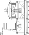
- reactor 1 has been shown to be inefficient and to have an inadequate effect with considerable wear and tear. This is primarily due to the poor feeding of the material to be broken down into an annular space 10 ( 9 ) inside the reactor and the lack of preconditioning of the material to be treated.
- the mixture to be broken down falls directly through a funnel-shaped material inlet (hopper) onto a rotatable rotor 3 and is thrown above the annular space 10 against the housing of a stationary stator 2 .
- the aim of the present invention is therefore to improve the device known from the prior art to the effect that it is more efficient and environmentally friendly Separation of composite materials and mixtures of substances is made possible, with the service life of such a device being increased and measures being provided with which, over the entire service life of such a device, the composite materials to be separated in such a device can be broken down as uniformly and reliably as possible, despite wear and tear over time , namely for the widest possible range of differently composed composite materials.
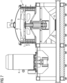
- a preferred embodiment of a device according to the invention (reactor 1) for separating composite materials and mixtures is in 7 shown.
- known device comprises in 7
- the preferred embodiment shown of a device according to the invention (reactor 1 ) has a drive unit 4 for driving a rotor 3 , which is connected to a bearing/shaft unit, which preferably has an axis of rotation aligned essentially parallel to the force of gravity.
- the rotor 3 At the in 7 and 8 shown reactor 1 the rotor 3 at least one rotor tool 6 ( 9 ) on.
- the rotatable rotor 3 is surrounded by a stationary built-in stator 2 , which in turn is in an annular space 10 ( 9 ) pointing stator tools 7 ( 9 ) having.
- a rotor can also enclose a stator.
- the rotor 3 and the stator 2 are preferably designed to be essentially cylindrical inside the reactor 1 .
- material flow other than cylindrical shapes for the rotor 3 and the stator 2 can also be used.
- the known device shown (reactor 1 ) comprises a material inlet in the form of a simple hopper 5b , through which the material flow to be fed to the reactor 1 falls into the interior of the reactor 1 .
- the material to be separated is fed in from above the rotor 3 and the stator 2 , it arrives at the in 8 shown known device uncontrolled in the ring area 10 ( 9 ), where it is crushed between rotor tools 6 and stator tools 7 and from where it then reaches a material outlet 9 below the rotor 3 and the stator 2 .
- the material inlet is designed in the form of an injector mixer 5a .
- This enables a metered supply of pretreated material in the material flow to be supplied, in particular broken material, into the interior of the reactor 1 .
- the injector mixer 5a enables a variable dosing of a working fluid, which can be admixed to the material flow to be digested in the injector mixer 5a under conditions that change over time.
- a curved disk 8 is fitted between the injector mixer 5a on the one hand and the rotor 3 and stator 2 on the other hand inside the reactor 1 in order to direct a stream of composite material to be broken down to the injector mixer 5a in a targeted manner into the engagement area in the annular space 10 ( 9 ) between the rotor tools 6 and the stator tools 7 to deflect.
- the disc 8 is concavely arched away from a material flow fed from above into the interior of the reactor 1 through the injector-mixer 5a . This ensures that fragments of the material flow fed through the injector-mixer 5a into the interior of the reactor 1 and to be further broken down there on the surface of the curved disk 8 are directed in a targeted manner into the ring-shaped engagement area (ring area 10 ) between the rotor tools 6 and the stator tools 7 to be directed.
- the curved disc 8 thus enables a targeted alignment of the material flow to be broken down inside the reactor 1 to the area where the rotor tools 6 and the stator tools 7 carry out their desired mechanical comminution work on the outside supplied fragments can unfold directly and without detours in the material flow to be broken down. This increases the efficiency with which the supplied material flow is broken up. Furthermore, unnecessary wear and tear on parts in the interior of the reactor 1 , which are exposed to a chaotic flow of material in the prior art, is prevented.
- the curved disk 8 inside the reactor 1 can be adjusted in the direction of the axis of rotation of the rotor 3 .
- the distance between the curved disk 8 and the injector-mixer 5a as well as the rotor 3 and stator 2 can be optimally adjusted in the vertical direction.
- the targeted deflection of the material flow introduced through the injector-mixer 5a into the interior of the reactor 1 into the engagement area between the rotor tools 6 and the stator tools 7 can be further optimized.
- the injector mixer 5a at the in 7 shown device according to the invention (reactor 1 ), a gas-liquid mixture (fluid) is applied to the material flow to be fed and broken down, with which the fluid is intensively mixed in 1 shown, is used, the material flow of broken material from composite materials (in particular electronic scrap components) to be subsequently fed to the injector mixer 5a is pre-shredded by means of a novel two- or three-axis plate crusher, as is shown in figure 5 is shown. In contrast to conventional plate crushers, this new plate crusher works in two or three directions (axes).
- a two-axis plate crusher is shown.
- Such a new type of plate crusher causes the material to be broken down by mutual pressure from essentially perpendicular directions to break it up into individual components and the form-fitting structures in the material flow are eliminated. This allows certain individual components to be selected before the material stream is actually introduced into the interior of the reactor 1 of the device according to the invention (reactor 1 ) and, if necessary, enables a pre-separation of fractional components occurring before entering the interior of the reactor 1 .
- further means for pre-sorting fragments from the material flow to be fed into the injector mixer 5a in the form of, in particular, lifting magnets, induction separators and/or multi-sensor separators can be connected between the plate crusher and the injector mixer 5a .
- further means serving for comminution can be connected between the lifting magnets, induction separators and/or multi-sensor separators on the one hand and the injector mixer 5a on the other.
- These further means used for comminution can in particular be shredders, hammer mills and/or granulators which are designed to comminute further fragments from the material flow to be fed to reactor 1 to a size of ⁇ 15 mm and to mix them homogeneously.
- the material stream to be digested is fed to the reactor 1 according to the invention ( 7 ) with the addition of a gas-liquid mixture (fluid) in the injector-mixer 5a for the actual digestion in the reactor 1 .
- the material flow to be processed has a suitable composition right from the start (e.g. in the case of soft plastic composite foils that neither have to be broken up in a plate crusher, nor can they be influenced by lifting magnets, nor can they be crushed by hammer mills), then these optional steps can be followed by the Pre-crushing and intermediate separation can be completely or at least partially dispensed with.
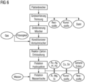
- the optional steps “plate crusher”, “coarse screening/separation” and “crushing/mixer” in 6 are installed in front of a reactor 1 according to the invention or omitted as required, depending on the starting materials to be processed.
- WO2017/036 534 A1 is only known that the material with the addition of ambient air via a hopper 5b ( 8 ) is fed to the reactor 1 .
- a significant improvement in the mode of operation of such a reactor 1 when breaking down composite materials can be achieved by suitable addition of a fluid under conditions specifically adapted to the materials to be broken down, since this achieves a targeted tribomechanical and mechanochemical action of the fluid on the composite materials to be broken down can be.
- the liquids mentioned above are fed to the injector-mixer 5a under atmospheric pressure and the gases mentioned above at 500-800 kPa while adding the solids of the material stream to be digested.
- the density of the fluid can be significantly influenced by an increased proportion of liquid or gas.
- the thermal energy generated in the process by friction is efficiently dissipated, favored by the liquid content.
- An increased density of the fluid leads to a longer dwell time of the solid (composite material to be broken down in the material flow to be supplied) in the annular space 10 inside the reactor 1 .
- an increased proportion of liquid leads to electrostatic potential equalization between the particles in the material flow, which prevents electrostatic charging of the particles.
- a further separation of the broken down components can optionally take place on water separating tables, hydrocyclones and flotation or sedimentation tanks or in filters. This is in 6 illustrated.
- the mixture discharged from an optionally activated cyclone or filter in the material flow to be discharged from the interior of the reactor 1 can be wetted with water immediately after leaving the interior of the reactor 1 through an optional Venturi nozzle. This has the decisive advantage that any formation of dust is prevented and all structures, even the finest, such as e.g. B. precious metals or rare earth metals can be detected.
- process step 3 is also not required, since in this case the material can be fed directly to the reactor.
- FIG. 6 shows a schematic overview of the individual stations or components that occur in an inventive device and in an inventive method.
- the physical differences between the materials (composite elements) in the composite are used to break down the composite. These physical differences naturally occur at boundary layers, i.e. where an individual material separates from another neighboring material.
- additives in particular water and gas, preferably also conditioned ambient air.
- the heat generated during the process is dissipated by utilizing the liquid or water content in the fluid.
- the mechanical stress on the composite material leads to the layer-by-layer detachment (delamination) of the materials by forming, which also turns out differently due to the different recovery behavior of the composite materials.
- the gas-liquid mixture (fluid) which is supplied to the device in the injector mixer 5a, promotes the breakdown of the elastic parts, such as plastics, rubber, etc., by increasing the absorption of the vibrations that occur.
- a comminution or pulverization is not aimed at.
- the supply of the material to be processed via an injector mixer 5a, such as a venturi mixer, in which a gas-liquid mixture is mixed with the solid to be processed (composite material particles in the material flow to be supplied).
- the fluid can preferably consist of air and water, or in an application in which inerting is required, nitrogen or argon can also be supplied.
- a mixture such as lime and wood flour can be added. On the one hand, this prevents oxidation and, on the other hand, it enables the mixture to be discharged in a solid form.
- the fluid When wear occurs on the rotor 3 or stator 2 in the reactor 1 , the fluid is adjusted in order to maintain the parameters required for the breakdown. Due to the wear and tear on the rotor 3 and stator 2 , the flow rate of the material through the annular space 10 is increased considerably and the residence time in the reactor 1 is thus shortened, thereby preventing a satisfactory digestion of the material. However, if the density of the fluid is increased, a longer dwell time in the annular space 10 is achieved, which in turn ensures that the material is adequately broken down.
- the mixture is fed directly to the annular space 10 ( 9 ) is supplied without a collision with the stator 2 in front of the annular space 10 .
- Entry into the annular space 10 where the material is broken down, can thus take place in a controllable manner under constant parameters.
- the wear, in particular in front of the entry zone of the material into the annular space 10 is significantly reduced. As a further effect, there is a higher throughput in the device, since there are no longer any losses due to uncontrolled feeding of the material.
- reactor 1 a device (reactor 1 ) is required, as is shown in 7 is shown and which is continuously filled with a mixture of gas, liquid and the composite material to be treated. This stream of material to be supplied is mixed or preconditioned shortly before reactor 1 .
- this mixture should preferably be added in a ratio of the following volume units or ratios: Solid (composite material) 2 - 5 volumes to 1.2 - 1.5 volumes of liquid (preferably water) and to 5000 - 12000 volumes of gas (preferably conditioned ambient air).
- This mixture is fed to the reactor 1 , which consists of a rotating part (rotor 3 ) and a fixed part (stator 2). It has been shown that the arrangement of the axes (horizontal or vertical) is not of crucial importance for the actual pulping process of the material. However, for optimal feeding, it has proven practical to feed the material-gas-liquid mixture from above into a vertically arranged device (reactor).
- the material to be treated (input) is subjected to an enormous particle acceleration, whereby mechanochemical (i.e. caused by the action of the fluid or the components contained in the fluid) and tribomechanical (i.e. caused by the high-frequency, mutually inverse thrusts described below) effects come into play , which subsequently lead to the breakdown or detachment of the individual layers.
- mechanochemical i.e. caused by the action of the fluid or the components contained in the fluid
- tribomechanical i.e. caused by the high-frequency, mutually inverse thrusts described below
- This process is carried out by the in 7 shown inventive device (reactor 1 ) accomplished.
- the operation of this device is as follows: In a reactor 1 there is a vertically arranged rotating part (rotor) 3 which can be increased by the drive 4 to a circumferential speed of up to 300 m/s.
- the mixture of solid (composite materials) and fluid preconditioned in the injector mixer 5a is exposed between rotor tools 6 and stator tools 7 to different levels of tribomechanical and mechanochemical conditions, in which the composite material breaks down or delaminates.
- Through the adjustable curved disc 8 there is a targeted acceleration and deflection of the mixture in the Engagement area (annular space 10 ) between the rotor 3 and the stator 2 . After digestion, the mixture is withdrawn from the reactor 1 and fed to the material discharge system 9 .
- the residence time in the reactor 1 can be influenced by the peripheral speed of the rotor 3 on the one hand and by increasing the proportion of fluid and the composition thereof on the other.
- Brittle parts become fine particles, metals into sphere-like deformed layers and elastic parts into flake or chip structures.
- the overall range of the particle size distribution is between a few micrometers up to the size of the supplied input, consequently the supply size of typically 15 mm.
- the materials are different in this range, enriched in normal distributions.
- the broken down materials (layers) should not be crushed.
- the breakdown does not take place by means of pulverization, crushing, or acceleration caused by turbulence or the like.
- the digestion takes place through mechanochemical and tribomechanical effects, which are caused by the mixing of gas with water (fluid) and the input material (composite material) by the impact of the rotor and stator elements.
- working gases and/or working liquids that act on the materials to be broken down and react chemically with them can optionally be added to the device according to the invention to improve the efficiency or speed when breaking down the material flow to be processed.
- a decisive advantage of the present invention is precisely that the device according to the invention can achieve sufficient efficiency for a large number of composite materials to be broken down simply by purely physical processing steps only with the addition of water and conditioned ambient air, so that a complex and cost-intensive provision of special chemicals is required (and their possibly subsequent disposal, which is also very time-consuming and cost-intensive) can in principle also be completely dispensed with.
Priority Applications (1)
| Application Number | Priority Date | Filing Date | Title |
|---|---|---|---|
| EP21306396.9A EP4163025A1 (fr) | 2021-10-05 | 2021-10-05 | Dispositif et procédé de décomposition de matières composites et de leurs mélanges en composants de matières séparés |
Applications Claiming Priority (1)
| Application Number | Priority Date | Filing Date | Title |
|---|---|---|---|
| EP21306396.9A EP4163025A1 (fr) | 2021-10-05 | 2021-10-05 | Dispositif et procédé de décomposition de matières composites et de leurs mélanges en composants de matières séparés |
Publications (1)
| Publication Number | Publication Date |
|---|---|
| EP4163025A1 true EP4163025A1 (fr) | 2023-04-12 |
Family
ID=78516725
Family Applications (1)
| Application Number | Title | Priority Date | Filing Date |
|---|---|---|---|
| EP21306396.9A Pending EP4163025A1 (fr) | 2021-10-05 | 2021-10-05 | Dispositif et procédé de décomposition de matières composites et de leurs mélanges en composants de matières séparés |
Country Status (1)
| Country | Link |
|---|---|
| EP (1) | EP4163025A1 (fr) |
Citations (4)
| Publication number | Priority date | Publication date | Assignee | Title |
|---|---|---|---|---|
| US5938128A (en) * | 1994-03-23 | 1999-08-17 | Engel; Rudolf | Process and apparatus for treating composite elements |
| WO2006117065A1 (fr) | 2005-04-29 | 2006-11-09 | Silver Cay Worldwide Corp. | Dispositif et procede pour traiter des elements composites |
| US20130270372A1 (en) * | 2010-12-01 | 2013-10-17 | Swiss Redux Engineering Ag | Device for separating composite materials |
| WO2017036534A1 (fr) | 2015-09-03 | 2017-03-09 | Graf Deniz | Procédé et dispositif pour séparer des matériaux composites et des mélanges, en particulier des mélanges de matières solides et des scories |
-
2021
- 2021-10-05 EP EP21306396.9A patent/EP4163025A1/fr active Pending
Patent Citations (4)
| Publication number | Priority date | Publication date | Assignee | Title |
|---|---|---|---|---|
| US5938128A (en) * | 1994-03-23 | 1999-08-17 | Engel; Rudolf | Process and apparatus for treating composite elements |
| WO2006117065A1 (fr) | 2005-04-29 | 2006-11-09 | Silver Cay Worldwide Corp. | Dispositif et procede pour traiter des elements composites |
| US20130270372A1 (en) * | 2010-12-01 | 2013-10-17 | Swiss Redux Engineering Ag | Device for separating composite materials |
| WO2017036534A1 (fr) | 2015-09-03 | 2017-03-09 | Graf Deniz | Procédé et dispositif pour séparer des matériaux composites et des mélanges, en particulier des mélanges de matières solides et des scories |
Similar Documents
| Publication | Publication Date | Title |
|---|---|---|
| DE69816070T2 (de) | Verfahren zur Behandlung von Schredderstaub | |
| DE102011086298B4 (de) | Vorrichtung und Verfahren zur selektiven Trennung von Polyurethanschaum und Fasern aus Automobilschredderrückstand | |
| DE102007029498A1 (de) | Verfahren, Anlage und Vorrichtungen zur Aufbereitung kunststoffhaltiger Abfälle | |
| EP2268406B1 (fr) | Procédé et installation pour le traitement de déchets à teneur élevée en matières plastiques | |
| EP2646234B1 (fr) | Dispositif et procede de séparation de matériaux composites | |
| WO2000053324A1 (fr) | Procede et dispositif pour valoriser des dechets de broyeur ou d'autres matieres composites similaires et utilisation d'un broyeur a percussion rotorique | |
| DE69934183T2 (de) | Verfahren zur Herstellung von Glassand und System dafür | |
| EP1332002B1 (fr) | Installation et procede pour traiter des residus de dechiquetage et utilisation d'une fraction de sable ainsi produite | |
| WO2002066164A1 (fr) | Installation et procede de traitement de minerais metalliferes | |
| WO2002034401A1 (fr) | Installation et procede pour traiter des residus de dechiquetage | |
| DE19726105A1 (de) | Verfahren und Anlage zur Aufbereitung von Elektronik-Schrott und zur Anreicherung verwertbarer, insbesondere Edelmetalle enthaltender Bestandteile | |
| WO2003103859A2 (fr) | Procede et dispositif pour le traitement de materiaux, de materiaux composites et de leurs composes | |
| DE19755629A1 (de) | Verfahren zur Aufbereitung der Shredderleichtfraktion aus Shredderanlagen | |
| EP0751831B1 (fr) | Procede et dispositif pour le traitement d'elements composites | |
| DE19519516C2 (de) | Verfahren und Vorrichtung zur Aufbereitung von Faserbestandteile und Fremdbestandteile enthaltenden Faserstoffen, insbesondere von Alt-Mineralwolle | |
| EP3253493B1 (fr) | Dispositif de broyage pour récupération de matières secondaires d'un matériau mis au rebut et procédé de commande dudit dispositif | |
| EP3259080B1 (fr) | Dispositif pour séparer des matériaux composites et des mélanges, en particulier des mélanges de matières solides et des scories | |
| EP4163025A1 (fr) | Dispositif et procédé de décomposition de matières composites et de leurs mélanges en composants de matières séparés | |
| DE4442631C2 (de) | Verfahren und Anlage zur Aufbereitung der in Shredderanlagen anfallenden Leichtfraktion | |
| DE19915481A1 (de) | Verfahren zur Gewinnung organischer und anorganischer Bestandteile aus Materialien einer Shredderleichtfraktion sowie Anlage zur Durchführung eines entsprechenden Verfahrens | |
| EP0330046B1 (fr) | Procédé de récupération de matières plastiques à partir de déchets métaux/plastiques | |
| DE102018123115A1 (de) | Verfahren und Anlage zum Aufbereiten von Material, das Zementstein enthält | |
| EP0623390A1 (fr) | Procédé et installation pour le traitement mécanique de mélanges de déchets | |
| EP0125435A2 (fr) | Procédé et installation de préparation de matières métalliques enrobées et d'obtention de particules métallifères sphéroidales | |
| DE10334646A1 (de) | Verfahren und Anlage zur Aufbereitung der Schredderleichtfraktion aus der Zerkleinerung von Schrotten und metallhaltigen Abfällen |
Legal Events
| Date | Code | Title | Description |
|---|---|---|---|
| PUAI | Public reference made under article 153(3) epc to a published international application that has entered the european phase |
Free format text: ORIGINAL CODE: 0009012 |
|
| STAA | Information on the status of an ep patent application or granted ep patent |
Free format text: STATUS: THE APPLICATION HAS BEEN PUBLISHED |
|
| AK | Designated contracting states |
Kind code of ref document: A1 Designated state(s): AL AT BE BG CH CY CZ DE DK EE ES FI FR GB GR HR HU IE IS IT LI LT LU LV MC MK MT NL NO PL PT RO RS SE SI SK SM TR |
|
| STAA | Information on the status of an ep patent application or granted ep patent |
Free format text: STATUS: REQUEST FOR EXAMINATION WAS MADE |
|
| 17P | Request for examination filed |
Effective date: 20231010 |
|
| RBV | Designated contracting states (corrected) |
Designated state(s): AL AT BE BG CH CY CZ DE DK EE ES FI FR GB GR HR HU IE IS IT LI LT LU LV MC MK MT NL NO PL PT RO RS SE SI SK SM TR |