EP4163025A1 - Device and method for breaking up composite materials and mixtures thereof into individual material components - Google Patents
Device and method for breaking up composite materials and mixtures thereof into individual material components Download PDFInfo
- Publication number
- EP4163025A1 EP4163025A1 EP21306396.9A EP21306396A EP4163025A1 EP 4163025 A1 EP4163025 A1 EP 4163025A1 EP 21306396 A EP21306396 A EP 21306396A EP 4163025 A1 EP4163025 A1 EP 4163025A1
- Authority
- EP
- European Patent Office
- Prior art keywords
- material flow
- reactor
- discharged
- rotor
- composite materials
- Prior art date
- Legal status (The legal status is an assumption and is not a legal conclusion. Google has not performed a legal analysis and makes no representation as to the accuracy of the status listed.)
- Pending
Links
- 239000000463 material Substances 0.000 title claims abstract description 164
- 239000002131 composite material Substances 0.000 title claims abstract description 65
- 239000000203 mixture Substances 0.000 title claims abstract description 43
- 238000000034 method Methods 0.000 title claims abstract description 40
- 239000012530 fluid Substances 0.000 claims abstract description 36
- 239000007788 liquid Substances 0.000 claims abstract description 28
- 239000002245 particle Substances 0.000 claims description 26
- XLYOFNOQVPJJNP-UHFFFAOYSA-N water Substances O XLYOFNOQVPJJNP-UHFFFAOYSA-N 0.000 claims description 26
- 238000000926 separation method Methods 0.000 claims description 20
- 229910052751 metal Inorganic materials 0.000 claims description 12
- 239000002184 metal Substances 0.000 claims description 12
- 239000004033 plastic Substances 0.000 claims description 12
- 229920003023 plastic Polymers 0.000 claims description 12
- 229910052782 aluminium Inorganic materials 0.000 claims description 11
- XAGFODPZIPBFFR-UHFFFAOYSA-N aluminium Chemical compound [Al] XAGFODPZIPBFFR-UHFFFAOYSA-N 0.000 claims description 11
- 239000012080 ambient air Substances 0.000 claims description 10
- RYGMFSIKBFXOCR-UHFFFAOYSA-N Copper Chemical compound [Cu] RYGMFSIKBFXOCR-UHFFFAOYSA-N 0.000 claims description 9
- 239000000725 suspension Substances 0.000 claims description 9
- 239000010949 copper Substances 0.000 claims description 8
- 229910052802 copper Inorganic materials 0.000 claims description 8
- 230000029087 digestion Effects 0.000 claims description 8
- 150000002739 metals Chemical class 0.000 claims description 8
- 239000007787 solid Substances 0.000 claims description 8
- 238000005188 flotation Methods 0.000 claims description 6
- 239000012634 fragment Substances 0.000 claims description 6
- 239000003570 air Substances 0.000 claims description 5
- 230000001143 conditioned effect Effects 0.000 claims description 5
- 239000010970 precious metal Substances 0.000 claims description 5
- 230000006698 induction Effects 0.000 claims description 4
- 229910052761 rare earth metal Inorganic materials 0.000 claims description 4
- 150000002910 rare earth metals Chemical class 0.000 claims description 4
- 238000002156 mixing Methods 0.000 claims description 3
- 239000013049 sediment Substances 0.000 claims description 3
- 229910000881 Cu alloy Inorganic materials 0.000 claims description 2
- 230000005284 excitation Effects 0.000 claims description 2
- 230000037230 mobility Effects 0.000 claims 3
- 238000011144 upstream manufacturing Methods 0.000 claims 2
- 238000000354 decomposition reaction Methods 0.000 claims 1
- 238000007599 discharging Methods 0.000 claims 1
- 230000017525 heat dissipation Effects 0.000 claims 1
- 230000003993 interaction Effects 0.000 claims 1
- 230000009471 action Effects 0.000 abstract description 3
- 239000007789 gas Substances 0.000 description 12
- 230000008569 process Effects 0.000 description 11
- 239000000126 substance Substances 0.000 description 8
- 239000002699 waste material Substances 0.000 description 8
- 230000000694 effects Effects 0.000 description 7
- 238000004519 manufacturing process Methods 0.000 description 7
- XKRFYHLGVUSROY-UHFFFAOYSA-N Argon Chemical compound [Ar] XKRFYHLGVUSROY-UHFFFAOYSA-N 0.000 description 6
- IJGRMHOSHXDMSA-UHFFFAOYSA-N Atomic nitrogen Chemical compound N#N IJGRMHOSHXDMSA-UHFFFAOYSA-N 0.000 description 6
- 230000015556 catabolic process Effects 0.000 description 6
- 239000002994 raw material Substances 0.000 description 5
- 230000001133 acceleration Effects 0.000 description 4
- 230000008901 benefit Effects 0.000 description 4
- 238000010276 construction Methods 0.000 description 4
- 239000010792 electronic scrap Substances 0.000 description 4
- 230000005484 gravity Effects 0.000 description 4
- 229910052500 inorganic mineral Inorganic materials 0.000 description 4
- 239000011707 mineral Substances 0.000 description 4
- 238000004064 recycling Methods 0.000 description 4
- 238000010521 absorption reaction Methods 0.000 description 3
- 229910052786 argon Inorganic materials 0.000 description 3
- 238000010586 diagram Methods 0.000 description 3
- 238000009826 distribution Methods 0.000 description 3
- 239000011152 fibreglass Substances 0.000 description 3
- 229910052757 nitrogen Inorganic materials 0.000 description 3
- 238000004806 packaging method and process Methods 0.000 description 3
- 239000004593 Epoxy Substances 0.000 description 2
- 239000004411 aluminium Substances 0.000 description 2
- 230000008859 change Effects 0.000 description 2
- 230000000739 chaotic effect Effects 0.000 description 2
- -1 copper Chemical class 0.000 description 2
- 239000000428 dust Substances 0.000 description 2
- 238000003912 environmental pollution Methods 0.000 description 2
- 239000003822 epoxy resin Substances 0.000 description 2
- 239000002923 metal particle Substances 0.000 description 2
- 239000003921 oil Substances 0.000 description 2
- 230000000704 physical effect Effects 0.000 description 2
- 229920000647 polyepoxide Polymers 0.000 description 2
- 238000010298 pulverizing process Methods 0.000 description 2
- 238000012216 screening Methods 0.000 description 2
- FIKFLLIUPUVONI-UHFFFAOYSA-N 8-(2-phenylethyl)-1-oxa-3,8-diazaspiro[4.5]decan-2-one;hydrochloride Chemical compound Cl.O1C(=O)NCC11CCN(CCC=2C=CC=CC=2)CC1 FIKFLLIUPUVONI-UHFFFAOYSA-N 0.000 description 1
- 229910000838 Al alloy Inorganic materials 0.000 description 1
- 235000008733 Citrus aurantifolia Nutrition 0.000 description 1
- 229910002549 Fe–Cu Inorganic materials 0.000 description 1
- WHXSMMKQMYFTQS-UHFFFAOYSA-N Lithium Chemical compound [Li] WHXSMMKQMYFTQS-UHFFFAOYSA-N 0.000 description 1
- 238000003723 Smelting Methods 0.000 description 1
- 229910000831 Steel Inorganic materials 0.000 description 1
- 235000011941 Tilia x europaea Nutrition 0.000 description 1
- 239000000654 additive Substances 0.000 description 1
- 239000002671 adjuvant Substances 0.000 description 1
- 230000004888 barrier function Effects 0.000 description 1
- 230000015572 biosynthetic process Effects 0.000 description 1
- 238000005253 cladding Methods 0.000 description 1
- 239000011365 complex material Substances 0.000 description 1
- 150000001875 compounds Chemical class 0.000 description 1
- 239000004020 conductor Substances 0.000 description 1
- 239000011162 core material Substances 0.000 description 1
- 230000002354 daily effect Effects 0.000 description 1
- 230000032798 delamination Effects 0.000 description 1
- 238000009792 diffusion process Methods 0.000 description 1
- 239000010793 electronic waste Substances 0.000 description 1
- 238000007786 electrostatic charging Methods 0.000 description 1
- 238000005421 electrostatic potential Methods 0.000 description 1
- 230000007613 environmental effect Effects 0.000 description 1
- 230000003203 everyday effect Effects 0.000 description 1
- 238000000605 extraction Methods 0.000 description 1
- 230000005294 ferromagnetic effect Effects 0.000 description 1
- 239000010419 fine particle Substances 0.000 description 1
- 235000013312 flour Nutrition 0.000 description 1
- 239000011888 foil Substances 0.000 description 1
- 239000003365 glass fiber Substances 0.000 description 1
- PCHJSUWPFVWCPO-UHFFFAOYSA-N gold Chemical compound [Au] PCHJSUWPFVWCPO-UHFFFAOYSA-N 0.000 description 1
- 239000010931 gold Substances 0.000 description 1
- 229910052737 gold Inorganic materials 0.000 description 1
- LNEPOXFFQSENCJ-UHFFFAOYSA-N haloperidol Chemical compound C1CC(O)(C=2C=CC(Cl)=CC=2)CCN1CCCC(=O)C1=CC=C(F)C=C1 LNEPOXFFQSENCJ-UHFFFAOYSA-N 0.000 description 1
- 229910001385 heavy metal Inorganic materials 0.000 description 1
- 230000006872 improvement Effects 0.000 description 1
- 239000012212 insulator Substances 0.000 description 1
- 239000004571 lime Substances 0.000 description 1
- 229910052744 lithium Inorganic materials 0.000 description 1
- 238000011068 loading method Methods 0.000 description 1
- 230000005291 magnetic effect Effects 0.000 description 1
- 238000012423 maintenance Methods 0.000 description 1
- 230000003647 oxidation Effects 0.000 description 1
- 238000007254 oxidation reaction Methods 0.000 description 1
- 230000002093 peripheral effect Effects 0.000 description 1
- JTJMJGYZQZDUJJ-UHFFFAOYSA-N phencyclidine Chemical class C1CCCCN1C1(C=2C=CC=CC=2)CCCCC1 JTJMJGYZQZDUJJ-UHFFFAOYSA-N 0.000 description 1
- 208000026438 poor feeding Diseases 0.000 description 1
- 238000004537 pulping Methods 0.000 description 1
- 238000011084 recovery Methods 0.000 description 1
- 230000009467 reduction Effects 0.000 description 1
- 230000004044 response Effects 0.000 description 1
- 238000004062 sedimentation Methods 0.000 description 1
- 230000035939 shock Effects 0.000 description 1
- 239000002893 slag Substances 0.000 description 1
- 239000010802 sludge Substances 0.000 description 1
- 239000007858 starting material Substances 0.000 description 1
- 239000010959 steel Substances 0.000 description 1
- 238000007669 thermal treatment Methods 0.000 description 1
- 229920001169 thermoplastic Polymers 0.000 description 1
- 239000004416 thermosoftening plastic Substances 0.000 description 1
- 239000002351 wastewater Substances 0.000 description 1
- 238000007704 wet chemistry method Methods 0.000 description 1
- 239000002023 wood Substances 0.000 description 1
Images


Classifications
-
- B—PERFORMING OPERATIONS; TRANSPORTING
- B09—DISPOSAL OF SOLID WASTE; RECLAMATION OF CONTAMINATED SOIL
- B09B—DISPOSAL OF SOLID WASTE
- B09B3/00—Destroying solid waste or transforming solid waste into something useful or harmless
- B09B3/30—Destroying solid waste or transforming solid waste into something useful or harmless involving mechanical treatment
- B09B3/35—Shredding, crushing or cutting
-
- B—PERFORMING OPERATIONS; TRANSPORTING
- B02—CRUSHING, PULVERISING, OR DISINTEGRATING; PREPARATORY TREATMENT OF GRAIN FOR MILLING
- B02C—CRUSHING, PULVERISING, OR DISINTEGRATING IN GENERAL; MILLING GRAIN
- B02C13/00—Disintegrating by mills having rotary beater elements ; Hammer mills
- B02C13/14—Disintegrating by mills having rotary beater elements ; Hammer mills with vertical rotor shaft, e.g. combined with sifting devices
- B02C13/18—Disintegrating by mills having rotary beater elements ; Hammer mills with vertical rotor shaft, e.g. combined with sifting devices with beaters rigidly connected to the rotor
- B02C13/1807—Disintegrating by mills having rotary beater elements ; Hammer mills with vertical rotor shaft, e.g. combined with sifting devices with beaters rigidly connected to the rotor the material to be crushed being thrown against an anvil or impact plate
-
- B—PERFORMING OPERATIONS; TRANSPORTING
- B02—CRUSHING, PULVERISING, OR DISINTEGRATING; PREPARATORY TREATMENT OF GRAIN FOR MILLING
- B02C—CRUSHING, PULVERISING, OR DISINTEGRATING IN GENERAL; MILLING GRAIN
- B02C21/00—Disintegrating plant with or without drying of the material
-
- B—PERFORMING OPERATIONS; TRANSPORTING
- B02—CRUSHING, PULVERISING, OR DISINTEGRATING; PREPARATORY TREATMENT OF GRAIN FOR MILLING
- B02C—CRUSHING, PULVERISING, OR DISINTEGRATING IN GENERAL; MILLING GRAIN
- B02C23/00—Auxiliary methods or auxiliary devices or accessories specially adapted for crushing or disintegrating not provided for in preceding groups or not specially adapted to apparatus covered by a single preceding group
- B02C23/02—Feeding devices
-
- B—PERFORMING OPERATIONS; TRANSPORTING
- B02—CRUSHING, PULVERISING, OR DISINTEGRATING; PREPARATORY TREATMENT OF GRAIN FOR MILLING
- B02C—CRUSHING, PULVERISING, OR DISINTEGRATING IN GENERAL; MILLING GRAIN
- B02C23/00—Auxiliary methods or auxiliary devices or accessories specially adapted for crushing or disintegrating not provided for in preceding groups or not specially adapted to apparatus covered by a single preceding group
- B02C23/08—Separating or sorting of material, associated with crushing or disintegrating
-
- B—PERFORMING OPERATIONS; TRANSPORTING
- B03—SEPARATION OF SOLID MATERIALS USING LIQUIDS OR USING PNEUMATIC TABLES OR JIGS; MAGNETIC OR ELECTROSTATIC SEPARATION OF SOLID MATERIALS FROM SOLID MATERIALS OR FLUIDS; SEPARATION BY HIGH-VOLTAGE ELECTRIC FIELDS
- B03B—SEPARATING SOLID MATERIALS USING LIQUIDS OR USING PNEUMATIC TABLES OR JIGS
- B03B9/00—General arrangement of separating plant, e.g. flow sheets
- B03B9/06—General arrangement of separating plant, e.g. flow sheets specially adapted for refuse
- B03B9/061—General arrangement of separating plant, e.g. flow sheets specially adapted for refuse the refuse being industrial
-
- B—PERFORMING OPERATIONS; TRANSPORTING
- B09—DISPOSAL OF SOLID WASTE; RECLAMATION OF CONTAMINATED SOIL
- B09B—DISPOSAL OF SOLID WASTE
- B09B5/00—Operations not covered by a single other subclass or by a single other group in this subclass
-
- B—PERFORMING OPERATIONS; TRANSPORTING
- B02—CRUSHING, PULVERISING, OR DISINTEGRATING; PREPARATORY TREATMENT OF GRAIN FOR MILLING
- B02C—CRUSHING, PULVERISING, OR DISINTEGRATING IN GENERAL; MILLING GRAIN
- B02C13/00—Disintegrating by mills having rotary beater elements ; Hammer mills
- B02C13/26—Details
- B02C13/286—Feeding or discharge
- B02C2013/28618—Feeding means
-
- B—PERFORMING OPERATIONS; TRANSPORTING
- B09—DISPOSAL OF SOLID WASTE; RECLAMATION OF CONTAMINATED SOIL
- B09B—DISPOSAL OF SOLID WASTE
- B09B2101/00—Type of solid waste
- B09B2101/15—Electronic waste
-
- B—PERFORMING OPERATIONS; TRANSPORTING
- B09—DISPOSAL OF SOLID WASTE; RECLAMATION OF CONTAMINATED SOIL
- B09B—DISPOSAL OF SOLID WASTE
- B09B2101/00—Type of solid waste
- B09B2101/15—Electronic waste
- B09B2101/17—Printed circuit boards [PCB]
Definitions
- the present invention relates to both a device and a method for breaking down composite materials and mixtures into individual material components.
- the present invention relates to a device according to the preamble of claim 1, as for example from WO2017/036 534 A1 is known.
- Such devices and methods are used to break down composite materials and form-fitting structures that contain composite materials and their mixtures by means of tribomechanical and mechanochemical treatment, with a breaking-up effective forming of a material flow consisting of the composite materials being carried out inside a reactor, selectively using physical differences between individual materials Particles in the material flow takes place.
- the digestion is carried out by shear forces between the layers along the phase boundaries of regions of different composite materials that meet one another.
- Electronic scrap in particular represents such a very complex type of waste, in which it is difficult to break down the individual components of the composite material.
- the aluminum serves as a barrier layer against light and is used to protect a product packaged in this laminate against diffusion.
- the aluminum layer is usually between two layers of plastic or is laminated on both sides. Depending on the application, the aluminum layer is between 6 and 80 ⁇ m.
- Such printed circuit boards consist of up to more than 50 layers of copper and fiberglass epoxy resins (FR4), which serve as an electrical conductor (copper) or as an insulator (fiberglass epoxy). These copper layers are between 17 and 34 ⁇ m thick. The thickness of the glass fiber epoxy resin layer is > 50 ⁇ m.
- the contact points can be provided with precious metals, in particular gold.
- the layer thicknesses are only a few ⁇ m.
- the material is durable and light.
- the layer thickness of the metal, eg aluminum, which is on the outside is between 100 - 300 ⁇ m, that of the plastic core material approx. 2 - 4 mm.
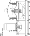
- reactor 1 has been shown to be inefficient and to have an inadequate effect with considerable wear and tear. This is primarily due to the poor feeding of the material to be broken down into an annular space 10 ( 9 ) inside the reactor and the lack of preconditioning of the material to be treated.
- the mixture to be broken down falls directly through a funnel-shaped material inlet (hopper) onto a rotatable rotor 3 and is thrown above the annular space 10 against the housing of a stationary stator 2 .
- the aim of the present invention is therefore to improve the device known from the prior art to the effect that it is more efficient and environmentally friendly Separation of composite materials and mixtures of substances is made possible, with the service life of such a device being increased and measures being provided with which, over the entire service life of such a device, the composite materials to be separated in such a device can be broken down as uniformly and reliably as possible, despite wear and tear over time , namely for the widest possible range of differently composed composite materials.
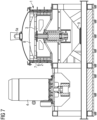
- a preferred embodiment of a device according to the invention (reactor 1) for separating composite materials and mixtures is in 7 shown.
- known device comprises in 7
- the preferred embodiment shown of a device according to the invention (reactor 1 ) has a drive unit 4 for driving a rotor 3 , which is connected to a bearing/shaft unit, which preferably has an axis of rotation aligned essentially parallel to the force of gravity.
- the rotor 3 At the in 7 and 8 shown reactor 1 the rotor 3 at least one rotor tool 6 ( 9 ) on.
- the rotatable rotor 3 is surrounded by a stationary built-in stator 2 , which in turn is in an annular space 10 ( 9 ) pointing stator tools 7 ( 9 ) having.
- a rotor can also enclose a stator.
- the rotor 3 and the stator 2 are preferably designed to be essentially cylindrical inside the reactor 1 .
- material flow other than cylindrical shapes for the rotor 3 and the stator 2 can also be used.
- the known device shown (reactor 1 ) comprises a material inlet in the form of a simple hopper 5b , through which the material flow to be fed to the reactor 1 falls into the interior of the reactor 1 .
- the material to be separated is fed in from above the rotor 3 and the stator 2 , it arrives at the in 8 shown known device uncontrolled in the ring area 10 ( 9 ), where it is crushed between rotor tools 6 and stator tools 7 and from where it then reaches a material outlet 9 below the rotor 3 and the stator 2 .
- the material inlet is designed in the form of an injector mixer 5a .
- This enables a metered supply of pretreated material in the material flow to be supplied, in particular broken material, into the interior of the reactor 1 .
- the injector mixer 5a enables a variable dosing of a working fluid, which can be admixed to the material flow to be digested in the injector mixer 5a under conditions that change over time.
- a curved disk 8 is fitted between the injector mixer 5a on the one hand and the rotor 3 and stator 2 on the other hand inside the reactor 1 in order to direct a stream of composite material to be broken down to the injector mixer 5a in a targeted manner into the engagement area in the annular space 10 ( 9 ) between the rotor tools 6 and the stator tools 7 to deflect.
- the disc 8 is concavely arched away from a material flow fed from above into the interior of the reactor 1 through the injector-mixer 5a . This ensures that fragments of the material flow fed through the injector-mixer 5a into the interior of the reactor 1 and to be further broken down there on the surface of the curved disk 8 are directed in a targeted manner into the ring-shaped engagement area (ring area 10 ) between the rotor tools 6 and the stator tools 7 to be directed.
- the curved disc 8 thus enables a targeted alignment of the material flow to be broken down inside the reactor 1 to the area where the rotor tools 6 and the stator tools 7 carry out their desired mechanical comminution work on the outside supplied fragments can unfold directly and without detours in the material flow to be broken down. This increases the efficiency with which the supplied material flow is broken up. Furthermore, unnecessary wear and tear on parts in the interior of the reactor 1 , which are exposed to a chaotic flow of material in the prior art, is prevented.
- the curved disk 8 inside the reactor 1 can be adjusted in the direction of the axis of rotation of the rotor 3 .
- the distance between the curved disk 8 and the injector-mixer 5a as well as the rotor 3 and stator 2 can be optimally adjusted in the vertical direction.
- the targeted deflection of the material flow introduced through the injector-mixer 5a into the interior of the reactor 1 into the engagement area between the rotor tools 6 and the stator tools 7 can be further optimized.
- the injector mixer 5a at the in 7 shown device according to the invention (reactor 1 ), a gas-liquid mixture (fluid) is applied to the material flow to be fed and broken down, with which the fluid is intensively mixed in 1 shown, is used, the material flow of broken material from composite materials (in particular electronic scrap components) to be subsequently fed to the injector mixer 5a is pre-shredded by means of a novel two- or three-axis plate crusher, as is shown in figure 5 is shown. In contrast to conventional plate crushers, this new plate crusher works in two or three directions (axes).
- a two-axis plate crusher is shown.
- Such a new type of plate crusher causes the material to be broken down by mutual pressure from essentially perpendicular directions to break it up into individual components and the form-fitting structures in the material flow are eliminated. This allows certain individual components to be selected before the material stream is actually introduced into the interior of the reactor 1 of the device according to the invention (reactor 1 ) and, if necessary, enables a pre-separation of fractional components occurring before entering the interior of the reactor 1 .
- further means for pre-sorting fragments from the material flow to be fed into the injector mixer 5a in the form of, in particular, lifting magnets, induction separators and/or multi-sensor separators can be connected between the plate crusher and the injector mixer 5a .
- further means serving for comminution can be connected between the lifting magnets, induction separators and/or multi-sensor separators on the one hand and the injector mixer 5a on the other.
- These further means used for comminution can in particular be shredders, hammer mills and/or granulators which are designed to comminute further fragments from the material flow to be fed to reactor 1 to a size of ⁇ 15 mm and to mix them homogeneously.
- the material stream to be digested is fed to the reactor 1 according to the invention ( 7 ) with the addition of a gas-liquid mixture (fluid) in the injector-mixer 5a for the actual digestion in the reactor 1 .
- the material flow to be processed has a suitable composition right from the start (e.g. in the case of soft plastic composite foils that neither have to be broken up in a plate crusher, nor can they be influenced by lifting magnets, nor can they be crushed by hammer mills), then these optional steps can be followed by the Pre-crushing and intermediate separation can be completely or at least partially dispensed with.
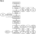
- the optional steps “plate crusher”, “coarse screening/separation” and “crushing/mixer” in 6 are installed in front of a reactor 1 according to the invention or omitted as required, depending on the starting materials to be processed.
- WO2017/036 534 A1 is only known that the material with the addition of ambient air via a hopper 5b ( 8 ) is fed to the reactor 1 .
- a significant improvement in the mode of operation of such a reactor 1 when breaking down composite materials can be achieved by suitable addition of a fluid under conditions specifically adapted to the materials to be broken down, since this achieves a targeted tribomechanical and mechanochemical action of the fluid on the composite materials to be broken down can be.
- the liquids mentioned above are fed to the injector-mixer 5a under atmospheric pressure and the gases mentioned above at 500-800 kPa while adding the solids of the material stream to be digested.
- the density of the fluid can be significantly influenced by an increased proportion of liquid or gas.
- the thermal energy generated in the process by friction is efficiently dissipated, favored by the liquid content.
- An increased density of the fluid leads to a longer dwell time of the solid (composite material to be broken down in the material flow to be supplied) in the annular space 10 inside the reactor 1 .
- an increased proportion of liquid leads to electrostatic potential equalization between the particles in the material flow, which prevents electrostatic charging of the particles.
- a further separation of the broken down components can optionally take place on water separating tables, hydrocyclones and flotation or sedimentation tanks or in filters. This is in 6 illustrated.
- the mixture discharged from an optionally activated cyclone or filter in the material flow to be discharged from the interior of the reactor 1 can be wetted with water immediately after leaving the interior of the reactor 1 through an optional Venturi nozzle. This has the decisive advantage that any formation of dust is prevented and all structures, even the finest, such as e.g. B. precious metals or rare earth metals can be detected.
- process step 3 is also not required, since in this case the material can be fed directly to the reactor.
- FIG. 6 shows a schematic overview of the individual stations or components that occur in an inventive device and in an inventive method.
- the physical differences between the materials (composite elements) in the composite are used to break down the composite. These physical differences naturally occur at boundary layers, i.e. where an individual material separates from another neighboring material.
- additives in particular water and gas, preferably also conditioned ambient air.
- the heat generated during the process is dissipated by utilizing the liquid or water content in the fluid.
- the mechanical stress on the composite material leads to the layer-by-layer detachment (delamination) of the materials by forming, which also turns out differently due to the different recovery behavior of the composite materials.
- the gas-liquid mixture (fluid) which is supplied to the device in the injector mixer 5a, promotes the breakdown of the elastic parts, such as plastics, rubber, etc., by increasing the absorption of the vibrations that occur.
- a comminution or pulverization is not aimed at.
- the supply of the material to be processed via an injector mixer 5a, such as a venturi mixer, in which a gas-liquid mixture is mixed with the solid to be processed (composite material particles in the material flow to be supplied).
- the fluid can preferably consist of air and water, or in an application in which inerting is required, nitrogen or argon can also be supplied.
- a mixture such as lime and wood flour can be added. On the one hand, this prevents oxidation and, on the other hand, it enables the mixture to be discharged in a solid form.
- the fluid When wear occurs on the rotor 3 or stator 2 in the reactor 1 , the fluid is adjusted in order to maintain the parameters required for the breakdown. Due to the wear and tear on the rotor 3 and stator 2 , the flow rate of the material through the annular space 10 is increased considerably and the residence time in the reactor 1 is thus shortened, thereby preventing a satisfactory digestion of the material. However, if the density of the fluid is increased, a longer dwell time in the annular space 10 is achieved, which in turn ensures that the material is adequately broken down.
- the mixture is fed directly to the annular space 10 ( 9 ) is supplied without a collision with the stator 2 in front of the annular space 10 .
- Entry into the annular space 10 where the material is broken down, can thus take place in a controllable manner under constant parameters.
- the wear, in particular in front of the entry zone of the material into the annular space 10 is significantly reduced. As a further effect, there is a higher throughput in the device, since there are no longer any losses due to uncontrolled feeding of the material.
- reactor 1 a device (reactor 1 ) is required, as is shown in 7 is shown and which is continuously filled with a mixture of gas, liquid and the composite material to be treated. This stream of material to be supplied is mixed or preconditioned shortly before reactor 1 .
- this mixture should preferably be added in a ratio of the following volume units or ratios: Solid (composite material) 2 - 5 volumes to 1.2 - 1.5 volumes of liquid (preferably water) and to 5000 - 12000 volumes of gas (preferably conditioned ambient air).
- This mixture is fed to the reactor 1 , which consists of a rotating part (rotor 3 ) and a fixed part (stator 2). It has been shown that the arrangement of the axes (horizontal or vertical) is not of crucial importance for the actual pulping process of the material. However, for optimal feeding, it has proven practical to feed the material-gas-liquid mixture from above into a vertically arranged device (reactor).
- the material to be treated (input) is subjected to an enormous particle acceleration, whereby mechanochemical (i.e. caused by the action of the fluid or the components contained in the fluid) and tribomechanical (i.e. caused by the high-frequency, mutually inverse thrusts described below) effects come into play , which subsequently lead to the breakdown or detachment of the individual layers.
- mechanochemical i.e. caused by the action of the fluid or the components contained in the fluid
- tribomechanical i.e. caused by the high-frequency, mutually inverse thrusts described below
- This process is carried out by the in 7 shown inventive device (reactor 1 ) accomplished.
- the operation of this device is as follows: In a reactor 1 there is a vertically arranged rotating part (rotor) 3 which can be increased by the drive 4 to a circumferential speed of up to 300 m/s.
- the mixture of solid (composite materials) and fluid preconditioned in the injector mixer 5a is exposed between rotor tools 6 and stator tools 7 to different levels of tribomechanical and mechanochemical conditions, in which the composite material breaks down or delaminates.
- Through the adjustable curved disc 8 there is a targeted acceleration and deflection of the mixture in the Engagement area (annular space 10 ) between the rotor 3 and the stator 2 . After digestion, the mixture is withdrawn from the reactor 1 and fed to the material discharge system 9 .
- the residence time in the reactor 1 can be influenced by the peripheral speed of the rotor 3 on the one hand and by increasing the proportion of fluid and the composition thereof on the other.
- Brittle parts become fine particles, metals into sphere-like deformed layers and elastic parts into flake or chip structures.
- the overall range of the particle size distribution is between a few micrometers up to the size of the supplied input, consequently the supply size of typically 15 mm.
- the materials are different in this range, enriched in normal distributions.
- the broken down materials (layers) should not be crushed.
- the breakdown does not take place by means of pulverization, crushing, or acceleration caused by turbulence or the like.
- the digestion takes place through mechanochemical and tribomechanical effects, which are caused by the mixing of gas with water (fluid) and the input material (composite material) by the impact of the rotor and stator elements.
- working gases and/or working liquids that act on the materials to be broken down and react chemically with them can optionally be added to the device according to the invention to improve the efficiency or speed when breaking down the material flow to be processed.
- a decisive advantage of the present invention is precisely that the device according to the invention can achieve sufficient efficiency for a large number of composite materials to be broken down simply by purely physical processing steps only with the addition of water and conditioned ambient air, so that a complex and cost-intensive provision of special chemicals is required (and their possibly subsequent disposal, which is also very time-consuming and cost-intensive) can in principle also be completely dispensed with.
Abstract
Die vorliegende Erfindung betrifft eine Vorrichtung und Verfahren zum Aufschliessen von Verbundwerkstoffen sowie formschlüssigen Strukturen, welche Verbundwerkstoffe beinhalten, sowie deren Gemenge. Dabei erfolgt mittels tribomechanischer und mechanochemischer Behandlung der oben genannten Materialien in einem Reaktor (1) unter Einwirkung eines Fluids, bestehend aus einem Gas und einer Flüssigkeit, eine aufschliessend wirkende Umformung der Verbundwerkstoffe selektiv aufgrund der physikalischen Unterschiede.

Description
Die vorliegende Erfindung betrifft sowohl eine Vorrichtung als auch ein Verfahren zum Aufschliessen von Verbundwerkstoffen und Gemischen in einzelne Werkstoffkomponenten. Insbesondere betrifft die vorliegende Erfindung eine Vorrichtung nach dem Oberbegriff des Anspruchs 1, wie sie z.B. aus
Dabei dienen solche Vorrichtungen und Verfahren dem Aufschliessen von Verbundwerkstoffen sowie formschlüssigen Strukturen, welche Verbundwerkstoffe beinhalten, sowie deren Gemischen, mittels tribomechanischer und mechanochemischer Behandlung, wobei im Innere eines Reaktors eine aufschliessend wirkende Umformung eines aus den Verbundwerkstoffen bestehenden Materialstroms selektiv unter Ausnutzung physikalischer Unterschiede zwischen einzelnen Partikeln im Materialstrom erfolgt. Dabei erfolgt der Aufschluss durch Schubkräfte zwischen den Schichtungen, entlang der Phasengrenzen aufeinandertreffender Regionen unterschiedlicher Verbundwerkstoffe.Such devices and methods are used to break down composite materials and form-fitting structures that contain composite materials and their mixtures by means of tribomechanical and mechanochemical treatment, with a breaking-up effective forming of a material flow consisting of the composite materials being carried out inside a reactor, selectively using physical differences between individual materials Particles in the material flow takes place. The digestion is carried out by shear forces between the layers along the phase boundaries of regions of different composite materials that meet one another.
Viele Werkstoffe können auf Grund der Komplexität ihres Aufbaus nur bedingt werkstofflich recycelt werden. Insbesondere Verbundwerkstoffe und Gemische derselben stellen hier eine Herausforderung dar. Da diese aus unserem täglichen Leben kaum mehr wegzudenken sind, besteht ein Bedürfnis, Lösungen zur werkstofflichen Verwertung von Verbundwerkstoffen und Werkstoffgemischen anzubieten.Due to the complexity of their structure, many materials can only be recycled to a limited extent. In particular, composite materials and mixtures thereof pose a challenge. Since these have become indispensable in our daily life, there is a need to offer solutions for the material recycling of composite materials and material mixtures.
Die Tatsache, dass täglich neue Materialien bzw. Werkstoffe zu den bereits bekannten Werkstoffen hinzukommen, macht es notwendig, beständig neue Lösungen zur wertstofflichen Verwertung von Werkstoffen zu entwickeln, welche einerseits die Auftrennung der einzelnen Werkstoffe ermöglichen und andererseits dabei die Entstehung umweltbelastender Abfälle oder Gase (CO2, NOX,..) vermeiden.The fact that new materials or materials are added to the already known materials every day makes it necessary to constantly develop new solutions for the recycling of materials, which on the one hand enable the separation of the individual materials and on the other hand the production of environmentally harmful waste or gases ( Avoid CO 2 , NO X ,..).
Diese Verbundwerkstoffe sind teilweise mit anderen Verbundwerkstoffen formschlüssig verbunden und deshalb schwer zu trennen.Some of these composite materials are positively connected to other composite materials and are therefore difficult to separate.
Zudem verhindern solche komplexen Materialkompositionen vielfach den Einsatz von gängigen Methoden wie einer thermischen Beaufschlagung oder einer Behandlung durch flüssige Chemikalien.In addition, such complex material compositions often prevent the use of common methods such as thermal treatment or treatment with liquid chemicals.
Insbesondere Elektronikschrott stellt einen solchen sehr komplexen Typ von Abfällen dar, bei dem ein Aufschliessen der einzelnen Komponenten des Verbundwerkstoffes schwierig ist.Electronic scrap in particular represents such a very complex type of waste, in which it is difficult to break down the individual components of the composite material.
Neben Leiterplatten, die aus Verbundwerkstoffen bestehen, umfasst Elektronikschrott wie er z.B. in
Weitere typische Abfälle, die einem Werkstoffrecycling nur schwer zugänglich sind, sind Verpackungsverbunde aus PE und Aluminium als dreischichtigem Laminat, wie in
Als weiteres Bespiel bekannter Verbundwerkstoffe zeigt
Zudem können die Kontaktstellen mit Edelmetallen, insbesondere Gold, versehen sein. Die Schichtdicken betragen jedoch nur einige wenige µm.In addition, the contact points can be provided with precious metals, in particular gold. However, the layer thicknesses are only a few µm.
Probleme bieten solche Verbundwerkstoffe nach der Verwendung dann, wenn diese Materialien aus dem Gebrauch genommen werden und folglich als Abfälle enden. Es ist hinlänglich bekannt, dass bereits in der Produktion dieser Verbundwerkstoffe erhebliche Mengen an Abfällen entstehen können.Such composites present problems after use when these materials are taken out of use and consequently end up as waste. It is well known that the production of these composite materials can generate significant amounts of waste.
So entstehen bei der Herstellung von gedruckten Schaltungen im Laufe des Herstellungsprozesses bis zu 20 % Produktionsabfälle.Up to 20% of production waste is generated during the manufacturing process of printed circuits.
Bei der Herstellung von Verpackungsverbunden, wie Tubenlaminaten, entstehen sogar bis zu 30 % Produktionsabfälle.In the manufacture of packaging composites, such as tube laminates, up to 30% production waste is generated.
Aus der Literatur geht hervor, dass bezogen auf die verwendete Menge an Metallen, beispielsweise Aluminium, nur rund ein Drittel überhaupt den Weg zurück in den Wirtschaftskreislauf findet. Bei den teureren Metallen wie Kupfer sind es rund 50 %. Dies ergibt sich aus der Tatsache, dass zum einen die Sammellogistik, und andererseits die Methoden für die Trennung der einzelnen Stoffe aus den Verbundwerkstoffen fehlen, bzw. zu teuer sind.The literature shows that, based on the amount of metals used, such as aluminum, only around a third find their way back into the economic cycle. For the more expensive metals such as copper, it is around 50%. This results from the fact that on the one hand the collection logistics and on the other hand the methods for separating the individual substances from the composite materials are missing or too expensive.
Die Komplexität dieser Materialien lässt meist ein werkstoffliches Recycling zu den Ausgangsrohstoffen zurück nicht zu, weshalb diese potenziellen Rohstoffquellen den Wirtschaftskreisläufen entzogen werden. Die damit verbundenen Kosten für die Umwelt sind im doppelten Masse problematisch. Es entstehen bei der Neuproduktion einerseits weitere Umweltbelastungen durch Verhüttung von Erzen, sowie andererseits durch die Verbringung der Abfälle, die nicht als Rohstoffe genützt werden können.The complexity of these materials usually does not allow mechanical recycling back to the original raw materials, which is why these potential sources of raw materials are withdrawn from the economic cycle. The associated environmental costs are doubly problematic. On the one hand, more are created during the new production Environmental pollution caused by the smelting of ores and, on the other hand, by the shipment of waste that cannot be used as raw materials.
Des Weiteren erfordert es enorme Mengen an Energie für die Primärgewinnung von Rohstoffen, insbesondere der Metalle, welche bei einer konsequenten Kreislaufwirtschaft hätten eingespart werden können.Furthermore, it requires enormous amounts of energy for the primary extraction of raw materials, especially metals, which could have been saved with a consistent circular economy.
Studien haben gezeigt, dass alleine durch eine konsequente Kreislaufwirtschaft ca. 20% der weltweit produzierten Energie eingespart werden könnte.Studies have shown that a consistent circular economy alone could save around 20% of the energy produced worldwide.
Die Materialien, welche zur Zeit mittels ineffizienten thermischen oder nasschemischen Prozessen verarbeitet werden, sind meist minderer Qualität und verursachen erhebliche Umweltbelastungen durch belastende Rückstände und einen verhältnismässig hohen Ausstoss an umweltbelastenden Gasen, Schlämmen, Abwässern und Schlacken.The materials that are currently processed using inefficient thermal or wet-chemical processes are mostly of inferior quality and cause considerable environmental pollution through polluting residues and a relatively high emission of polluting gases, sludge, waste water and slag.
Bei der in der
Ziel der vorliegenden Erfindung ist es deshalb, die aus dem Stand der Technik bekannte Vorrichtung dahingehend zu verbessern, dass eine effizientere und umweltschonendere Trennung von Verbundwerkstoffen und Stoffgemischen ermöglicht wird, wobei die Standzeit einer solchen Vorrichtung erhöht wird und Maßnahmen bereitgestellt werden, mit denen über die gesamte Lebensdauer einer solchen Vorrichtung trotz laufzeitbedingtem Verschleiss ein möglichst gleichmäßiges und zuverlässiges Aufschliessen der in einer solchen Vorrichtung zu trennenden Verbundwerkstoffe zu erzielen ist, und zwar für eine möglichst große Bandbreite unterschiedlich zusammengesetzter Verbundwerkstoffe.The aim of the present invention is therefore to improve the device known from the prior art to the effect that it is more efficient and environmentally friendly Separation of composite materials and mixtures of substances is made possible, with the service life of such a device being increased and measures being provided with which, over the entire service life of such a device, the composite materials to be separated in such a device can be broken down as uniformly and reliably as possible, despite wear and tear over time , namely for the widest possible range of differently composed composite materials.
Erfindungsgemäss wird diese Aufgabe durch eine Vorrichtung nach Anspruch 1 und ein Verfahren nach Anspruch 11 gelöst. Die weiteren Ansprüche betreffen vorteilhafte Ausführungsformen solcher Vorrichtungen und Verfahren.According to the invention, this object is achieved by a device according to claim 1 and a method according to claim 11. The further claims relate to advantageous embodiments of such devices and methods.
Vorteile und Merkmale der vorliegenden Erfindung ergeben sich insbesondere aus der nachfolgenden detaillierten Beschreibung von bevorzugten Ausführungsformen in Verbindung mit den beigefügten Figuren.Advantages and features of the present invention result in particular from the following detailed description of preferred embodiments in conjunction with the attached figures.
Es zeigen:
-
Fig. 1 eine schematische Darstellung von Elektronikschrott; -
Fig. 2 einen aus dem Stand der Technik bekannten Verpackungsverbund; -
Fig. 3 einen aus dem Stand der Technik bekannten Laminatverbundwerkstoff, der metallische Schichten und eine Glasfaserepoxid-Schicht aufweist; -
Fig. 4 einen weiteren aus dem Stand der Technik bekannten Laminatverbundwerkstoff, wie er z. B. im Fassadenbau oder Fahrzeugbau eingesetzt wird; -
Fig. 5 einen zweiachsigen Plattenbrecher, wie er in einer bevorzugten Ausführungsform einer erfindungsgemässen Vorrichtung zum Aufschliessen von Verbundwerkstoffen vor deren Zufuhr in Innere des Reaktors einer erfindungsgemässen Vorrichtung zum Einsatz kommen kann; -
Fig. 6 eine schematisches Diagramm der verschiedenen Schritte einer bevorzugten Ausführungsform eines erfindungsgemässen Verfahrens zum Aufschliessen von Verbundwerkstoffen in einer inFig. 7 gezeigten erfindungsgemäßen Vorrichtung; -
Fig. 7 eine Ausführungsform einer erfindungsgemässen Vorrichtung (Reaktor), welche mit einem Gemisch aus Gas, Flüssigkeit und den zu behandelnden Verbundmaterialien kontinuierlich befüllt werden kann, um eine kontinuierliche Durchführung eines erfindungsgemässen Verfahrens zu ermöglichen; -
Fig. 8 eine ausWO2017/036 534 A1 -
Fig. 9 eine Detailansicht eines Ringraums im Inneren eines inFig. 7 oder8 gezeigten Reaktors, wobei der Ringraum zwischen einem Rotor und einem Stator dort gebildet ist, wo Rotor- und Statorwerkzeuge miteinander auf Verbundwerkstoffkomponenten in einem dem Reaktor zuzuführenden Materialstrom einwirken können.
-
1 a schematic representation of electronic scrap; -
2 a packaging composite known from the prior art; -
3 a prior art laminate composite having metallic layers and a fiberglass epoxy layer; -
4 another known from the prior art laminate composite material, as z. B. is used in facade construction or vehicle construction; -
figure 5 a biaxial plate crusher, as can be used in a preferred embodiment of a device according to the invention for breaking up composite materials before they are fed into the interior of the reactor of a device according to the invention; -
6 a schematic diagram of the various steps of a preferred embodiment of a method according to the invention for digesting composite materials in an in7 shown device according to the invention; -
7 an embodiment of a device (reactor) according to the invention, which can be continuously filled with a mixture of gas, liquid and the composite materials to be treated, in order to enable continuous implementation of a method according to the invention; -
8 one outWO2017/036 534 A1 -
9 a detailed view of an annular space inside an in7 or8th shown reactor, wherein the annular space between a rotor and a stator is formed where rotor and stator tools can act together on composite material components in a material flow to be fed to the reactor.
Eine bevorzugte Ausführungsform einer erfindungsgemässen Vorrichtung (Reaktor 1) zum Trennen von Verbundwerkstoffen und Gemischen ist in
Wie bei der in
Dabei weist bei dem in
Der Rotor 3 und der Stator 2 sind bevorzugter Weise im Wesentlichen zylindrisch im Inneren des Reaktors 1 ausgebildet. Je nach Art und Zusammensetzung des aufzuschließenden Materialstroms können aber auch andere als zylindrische Formen für den Rotor 3 und den Stator 2 zum Einsatz kommen.The
Bei der in
Im Gegensatz dazu ist bei der in
Weiterhin ist bei der erfindungsgemässen Vorrichtung eine gewölbte Scheibe 8 zwischen dem Injektor-Mischer 5a einerseits und dem Rotor 3 und Stator 2 andererseits im Inneren des Reaktors 1 angebracht, um einem dem Injektor-Mischer 5a zuzuführenden Strom an aufzuschliessendem Verbundwerkstoffmaterial gezielt in den Eingriffsbereich im Ringraum 10 (
Die Scheibe 8 ist zu einem von oben in das Innere des Reaktors 1 durch den Injektor-Mischer 5a hinzugeführten Materialstrom konkav weggewölbt. Dadurch kann sichergestellt werden, dass Bruchstücke des durch den Injektor-Mischers 5a in das Inneren des Reaktors 1 zugeführten und dort weiter aufzuschliessenden Materialstroms auf der Oberfläche der gewölbten Scheibe 8 zielgerichtet in den ringförmigen Eingriffsbereich (Ringbereich 10) zwischen den Rotorwerkzeugen 6 und den Statorwerkzeugen 7 gelenkt werden. Die gewölbte Scheibe 8 ermöglicht also eine zielgerichtete Ausrichtung des aufzuschliessenden Materialstroms im Inneren des Reaktors 1 auf den Bereich, wo die Rotorwerkzeuge 6 und die Statorwerkzeugen 7 ihre gewünschte mechanische Zerkleinerungsarbeit an den von aussen zugeführten Bruchstücken im aufzuschließenden Materialstrom direkt und ohne Umwege entfalten können. Dadurch wird die Effizienz, mit der der zugeführte Materialstrom aufgeschlossen wird, erhöht. Weiterhin wird ein unnötiger Verschleiss an Teilen im Innenraum des Reaktors 1, die beim Stand der Technik einem chaotischen Materialzustrom ausgesetzt sind, verhindert.The
Bei einer besonders bevorzugten Ausführungsform der erfindungsgemässen Vorrichtung ist zudem zur weiteren Feinabstimmung vorgesehen, dass die gewölbte Scheibe 8 im Inneren des Reaktors 1 in Richtung der Drehachse des Rotors 3 verstellbar ist. Dadurch kann der Abstand der gewölbten Scheibe 8 sowohl zum Injektor-Mischer 5a als auch zum Rotor 3 und Stator 2 in vertikaler Richtung optimal angepasst werden. Dadurch kann die gezielte Ablenkung des durch den Injektor-Mischer 5a in das Innere des Reaktors 1 eingeführten Materialstroms in den Eingriffsbereich zwischen den Rotorwerkzeugen 6 und den Statorwerkzeugen 7 weiter optimiert werden. Eine solche Verstellung des Abstands zwischen der gewölbten Scheibe 8 und dem Injektor-Mischer 5a bzw. dem Rotor 3 und dem Stator 2 kann aber auch als Antwort auf ein sich eventuell über den Lauf der Zeit ergebendes Abstumpfen der Rotorwerkzeuge 6 und Statorwerkzeuge 7 durchgeführt werden.In a particularly preferred embodiment of the device according to the invention, it is also provided for further fine-tuning that the
Dadurch werden die bei der aus dem Stand der Technik bekannten Vorrichtung auftretenden Nachteile hinsichtlich des Verschleisses von Rotor- und Statorwerkzeugen 6, 7 und unzureichendem Wirkungsgrad beim weiteren Aufschliessen der Bruchstücke im Inneren des Reaktors 1 überwunden. Im Injektor-Mischer 5a kann bei der in
Bei dem in
Bei einer weiteren besonders bevorzugten Ausführungsform einer erfindungsgemässen Vorrichtung können weitere Mittel zum Vorsortieren von Bruchstücken aus dem in den Injektor-Mischer 5a zuzuführenden Materialstrom in Form von insbesondere Aushebemagneten, Induktionsabscheidern und/oder Multisensorseparatoren zwischen den Plattenbrecher und den Injektor-Mischer 5a geschaltet sind. Diese ermöglichen eine im Blockdiagramm einer Ausführungsform eines erfindungsgemässen Verfahrens in
Weiterhin können bei einer weiteren bevorzugten Ausführungsform der vorliegenden Erfindung weitere zum Zerkleinern dienende Mittel zwischen die Aushebemagneten, Induktionsabscheider und/oder Multisensorseparatoren einerseits sowie den Injektor-Mischer 5a andererseits geschaltet sein. Bei diesen weiteren zum Zerkleinern dienenden Mittel kann es sich insbesondere um Schredder, Hammermühlen und/oder Granulatoren handeln, die dazu ausgelegt sind, weitere Bruchstücke aus dem dem Reaktor 1 zuzuführenden Materialstrom auf eine Grössenordnung von < 15 mm zu zerkleinern und homogen zu vermischen. Diese ermöglichen eine im Blockdiagramm einer Ausführungsform eines erfindungsgemässen Verfahrens in
Nach dieser optionalen Vorzerkleinerung und Zwischenseparation in den Schritten "Plattenbrecher", "Grobsortierung" und "Zerkleinerung/Mischer" in
Liegt der aufzuschliessende Materialstrom aber bereits von Anfang an in einer geeigneten Zusammensetzung vor (z.B. bei weichen Kunststoffverbundfolien, die weder in einem Plattenbrecher gebrochen werden müssen, noch durch Aushebemagneten beeinflussbar sind, noch durch Hammermühlen zerkleinert werden könnten), so kann auf diese optionalen Schritte der Vorzerkleinerung und Zwischenseparation komplett oder zumindest teilweise verzichtet werden. Die optionalen Schritte "Plattenbrecher", "Grobsortierung/Trennung" und "Zerkleinerung/Mischer" in
Aus dem Stand der Technik nach
Besonders bevorzugte Prozessparameter für das dabei erfindungsgemäss zum Einsatz kommende Fluid im Mischer-Injektor 5a sind wie folgt:.Particularly preferred process parameters for the fluid used according to the invention in the mixer-
Die Eingangstemperatur der in das Fluid zu mischenden Flüssigkeit beträgt:
- zwischen 5 -25 °C für Wasser,
- für insbesondere bei einer gewünschten chemischen Inertisierung im Innere des Reaktors 1 zum Einsatz kommendem flüssigen Stickstoff zwischen -250 bis -200 °C, und
- für Öl zwischen 10-30 °C
- between 5 -25 °C for water,
- for liquid nitrogen between -250 to -200° C. used in particular for a desired chemical inerting inside the reactor 1 , and
- for oil between 10-30 °C
Die Eingangstemperatur der in das Fluid einzumischenden Gase beträgt:
- bei Umgebungsluft zwischen 10-30 °C,
- bei Argon zwischen 5 - 25 °C
- at ambient air between 10-30 °C,
- with argon between 5 - 25 °C
Die oben genannten Flüssigkeiten werden unter atmosphärischem Druck und die oben genannten Gase bei 500 - 800 kPa unter Zugabe des Feststoffes des aufzuschliessenden Materialstroms dem Injektor-Mischer 5a zugeführt. Dabei kann die Dichte des Fluids durch einen erhöhten Flüssigkeits- oder Gasanteil erheblich beeinflusst werden. Die im Prozess durch Friktionen entstehende Wärmeenergie wird, durch den Flüssigkeitsanteil begünstigt, effizient abgeführt. Eine erhöhte Dichte des Fluids führt zu einer längeren Verweilzeit des Feststoffes (aufzuschliessender Verbundwerkstoff im zuzuführenden Materialstrom) im Ringraum 10 im Inneren des Reaktors 1. Zudem führt ein erhöhter Anteil von Flüssigkeit zum elektrostatischen Potenzialausgleich zwischen den Partikeln im Materialstrom, wodurch eine elektrostatische Aufladung der Partikel verhindert wird.The liquids mentioned above are fed to the injector-
Dies unterscheidet sich vom Stand der Technik wie in
Des Weiteren kann nach dem Verlassen des Materials im Hauptstrom aus dem Inneren des Reaktors 1 durch den Materialauslass 9 optional eine weitere Separation der aufgeschlossenen Komponenten auf Wassertrenntischen, Hydrozyklonen und Flotations- bzw. Sedimentationsbecken oder in Filtern erfolgen. Dies ist in
Um diese Verbundwerkstoffe zu nutzen, bzw. als Rohstoffquelle zu erschliessen, werden diese Verbundwerkstoffe in erfindungsgemäss bevorzugter Weise einem mechanischen Nachbehandlungsprozess unterzogen. Der Sinn der Erfindung ist es, die einzelnen Materialien in einem zuzuführenden Materialstrom mittels der in
- 1.) Aufschluss der Strukturen, z.B. Computergehäuse, erfolgt durch einen Plattenbrecher (
Fig. 5 ), welcher einen wechselseitigen Druck von zwei (eventuell drei) beweglichen Platten auf die gegenüberliegenden, festen Platten ausübt. Die aufgebrachten Kräfte, welche auf die Computergehäuse wirken, führen dazu, dass die Struktur bzw. der Formschluss zerstört bzw. zerkleinert wird. Die Gehäuse und inneren Strukturen sind nun in einzelne Teile zerborsten und können danach mittels eines Räumers aus dem Innern des Plattenbrechers ausgetragen werden. - 2.) Trennung bzw. Grobsortierung der Materialien. Die nun freiliegenden Materialien, wie Kunststoffe, Leiterplatten, Blechteile usw., werden anschließend einer Zwischenseparation unterzogen. Dabei werden mittels eines Aushebemagnetes die Stahlgehäuse, bzw. generell ferromagnetische Anteile im aufzuschliessenden Materialstrom entzogen. Über Induktionsabscheider, bzw. Multisensorseparatoren, erfolgt die Trennung der Kunststoffanteile, sowie Fe-Cu-Komponenten (Transformatoren, Motoren und der Gleichen). Der Rest, welcher aus Verbundstoffen, wie Leiterplatten, Stecker, Kabeln usw. besteht, wird der nächsten Prozessstufe zugeführt.
- 3.) Der übrig gebliebene Teilstrom wird nun einer klassischen mechanischen Zerkleinerung in Schreddern, Hammermühlen, Granulatoren usw. zugeführt und auf eine Grösse von z.B. <15 mm verarbeitet. Das Material wird homogen gemischt und zur weiteren Verarbeitung bereitgestellt.
- 4.) Das Material wird nun unter Zugabe eines Fluids (Gas-Flüssigkeitsgemisch) dem Reaktor 1 in der erfindungsgemässen Vorrichtung über den Injektor-
Mischer 5a zudosiert, bevorzugter Weise bei den oben angegebenen Drücken und Temperaturen. Im Reaktor 1 erfolgt der eigentliche Aufschluss der Verbundwerkstoffe in einzelne Materialqualitäten. Diese werden ausgetragen und pneumatisch (d.h. durch eine Absaugung) dem Reaktor 1 entzogen. Der Prozess ist nachstehend näher beschrieben. Anschliessend erfolgt die Trennung des Gemenges und des Fluids in optional hinter den Reaktor 1 in den abzuführenden Materialstrom geschalteten Zyklonen und Filtersystemen. Alternativ kann das Gemenge als Suspension unter Zugabe von weiterer Flüssigkeit in einen optional in den abzuführenden Materialstrom hinter den Reaktor 1 geschalteten Venturimischer (nicht gezeigt) homogenisiert und über Pumpen (nicht gezeigt) der Dichtetrennung direkt zudosiert werden. - 5.) Das Gemenge wird dann durch eine Dichtetrennung unter Zugabe weiterer Flüssigkeit getrennt. Dabei können Flotationsbecken, Hydrozyklone und Wassertrenntische eingesetzt werden. In den (üblicherweise mit Wasser) befüllten Flotationsbecken, werden Stoffe mit einer Dichte <1 g/cm3 als nicht absetzbarer Teil entzogen. Dabei handelt es sich um Thermoplaste und andere organische Substanzen. Die schwereren Kunststoffe mit einer Dichte >1 g/cm3, werden zusammen mit den Mineralstoffen und Metallen als Sediment mittels einer Suspension in den aus dem Reaktor 1 abzuführenden Materialstrom optional geschalteten Wassertrenntischen bzw. Hydrozyklonen zugeführt. Dort kann eine Trennung in Kunststoffe, Aluminium und andere Leichtmetalle, Kupfer und Kupferlegierungen, Edelmetalle und angereicherten Seltenen Erdmetalle erfolgen. Die Separation erfolgt aufgrund des Vorhandenseins unterschiedlicher Dichten der aufzuschliessenden Materialien und der unterschiedlichen Beweglichkeiten der sich ihnen befindlichen Partikel in Fluiden. Dazu erfolgt eines vibratorische Anregung der schrägen Ebene eines Wassertrenntisches, welche das unterschiedliche Förderverhalten der einzelnen Materialien nutzt. Die Partikel der unterschiedlichen Verbundwerkstoffanteile zeigen durch ihre unterschiedlichen Dichten und Partikelgrößen unterschiedliche Beweglichkeiten relativ zueinander in einer Umgebungsflüssigkeit; dies führt bei der vibratorischen Anregung der Wassertrenntische zu einer Trennung der Partikelsorten auf einem Wassertrenntisch. Der Austrag erfolgt dann über wasserführende Rinnen, welche unterschiedlich angeordnet und ausgestaltet sind. Anschliessend wird das Material, falls notwendig, getrocknet. Die vorstehenden Prozessschritte 1) bis 5) beziehen sich bevorzugter Weise auf Materialien, welche Elektro- und Elektronikschrott (
Fig. 1 ) entstammen.
- 1.) The structures, e.g. computer housing, are broken down by a plate breaker (
figure 5 ), which exerts a reciprocal pressure of two (possibly three) movable plates on the opposite, fixed plates. The forces applied, which act on the computer housing, lead to the structure or the form fit being destroyed or crushed. The housing and internal structures have now burst into individual pieces and can then be removed from inside the plate crusher using a scraper. - 2.) Separation or rough sorting of the materials. The materials that are now exposed, such as plastics, printed circuit boards, sheet metal parts, etc., are then subjected to an intermediate separation. The steel housing or generally ferromagnetic parts in the material flow to be digested are removed by means of a lifting magnet. The plastic parts and Fe-Cu components (transformers, motors and the like) are separated using induction separators or multi-sensor separators. The rest, which consists of composite materials such as printed circuit boards, connectors, cables, etc., is fed into the next process step.
- 3.) The partial flow that is left is now fed to a classic mechanical comminution in shredders, hammer mills, granulators, etc. and processed to a size of <15 mm, for example. The material is mixed homogeneously and made available for further processing.
- 4.) The material is now metered into the reactor 1 in the device according to the invention via the
injector mixer 5a , with the addition of a fluid (gas-liquid mixture) , preferably at the pressures and temperatures specified above. In reactor 1 , the composite materials are actually broken down into individual material qualities. These are discharged and withdrawn from the reactor 1 pneumatically (ie by suction). The process is detailed below. The mixture and the fluid are then separated, optionally downstream of the reactor 1 , into the material stream to be discharged switched cyclones and filter systems. Alternatively, the mixture can be homogenized as a suspension with the addition of further liquid in a Venturi mixer (not shown) optionally connected in the material stream to be discharged downstream of the reactor 1 and metered directly into the density separator via pumps (not shown). - 5.) The mixture is then separated by density separation with the addition of more liquid . Flotation tanks, hydrocyclones and water separating tables can be used for this. In the flotation tanks (usually filled with water), substances with a density of <1 g/cm 3 are removed as a part that cannot be settled. These are thermoplastics and other organic substances. The heavier plastics with a density >1 g/cm 3 are fed together with the minerals and metals as sediment by means of a suspension into the material flow to be discharged from the reactor 1 to optionally switched water separating tables or hydrocyclones. There, a separation into plastics, aluminum and other light metals, copper and copper alloys, precious metals and enriched rare earth metals can take place. The separation takes place due to the presence of different densities of the materials to be broken down and the different mobility of the particles in fluids. For this purpose, a vibratory excitation of the inclined plane of a water separation table takes place, which uses the different conveying behavior of the individual materials. Due to their different densities and particle sizes, the particles of the different composite material components show different mobility relative to one another in a surrounding liquid; This leads to a separation of the particle types on a water separating table when the water separating tables are vibrated. The discharge then takes place via water-carrying channels, which are arranged and designed in different ways. If necessary, the material is then dried. The above process steps 1) to 5) preferably relate to materials which electrical and electronic scrap (
1 ) come from.
Materialien, welche nicht formschlüssig vorliegen (
Besteht das zu behandelnde Inputmaterial aus einem Gemenge, welches eine Grösse von < 15 mm aufweist, wird der Prozessschritt 3) ebenso nicht benötigt, da das Material in diesem Falle direkt dem Reaktor zugeführt werden kann.If the input material to be treated consists of a batch that is < 15 mm in size, process step 3) is also not required, since in this case the material can be fed directly to the reactor.
Wie in
Die Unterschiede zwischen den physikalischen Eigenschaften der einzelnen Werkstoffe wie insbesondere Dichte, Elastizität, Duktilität, Schwingungsabsorption werden unter Beigabe von Additiven insbesondere Wasser und Gas, vorzugsweise auch konditionierte Umgebungsluft unterstützt. Zudem wird unter Ausnützung des Flüssigkeits- bzw. Wasseranteils im Fluid die beim Prozess entstehenden Wärme abgeführt werden. Die mechanische Beaufschlagung des Verbundstoffes führt zur schichtweisen Ablösung (Delamination) der Materialien durch Umformung, welche durch das unterschiedliche Rückstellverhalten der Verbundmaterialien auch unterschiedlich ausfällt. Zudem wirkt das Gas-Flüssigkeitsgemisch (Fluid), welches im Injektor-Mischer 5a der Vorrichtung zugeführt wird, bei den elastischen Anteilen, wie Kunststoffe, Gummi usw. aufschlussfördernd durch eine erhöhte Absorption der entstehenden Schwingungen.The differences between the physical properties of the individual materials, such as in particular density, elasticity, ductility and vibration absorption, are supported with the addition of additives, in particular water and gas, preferably also conditioned ambient air. In addition, the heat generated during the process is dissipated by utilizing the liquid or water content in the fluid. The mechanical stress on the composite material leads to the layer-by-layer detachment (delamination) of the materials by forming, which also turns out differently due to the different recovery behavior of the composite materials. In addition, the gas-liquid mixture (fluid), which is supplied to the device in the
Eine Zerkleinerung oder Pulverisierung wird dabei nicht angestrebt.A comminution or pulverization is not aimed at.
Die Unterschiede der Streckgrenzen und der Elastizitäten der Verbundelemente führen letztlich zu einer Aufhebung des Verbundes an den Berührungsflächen.The differences in the yield points and the elasticity of the composite elements ultimately lead to a break in the bond at the contact surfaces.
Dabei erfolgt im Gegensatz zu der
Beim Eintreten von Verschleiss am Rotor 3 bzw. Stator 2 im Reaktor 1 werden Anpassungen des Fluids vorgenommen, um die zum Aufschluss notwendigen Parameter aufrecht zu erhalten. Durch den Verschleiss an Rotor 3 und Stator 2, wird die Durchflussgeschwindigkeit des Materials durch den Ringraum 10 erheblich erhöht und damit die Verweilzeit im Reaktor 1 verkürzt und dadurch wird ein zufriedenstellender Aufschluss des Materials vereitelt. Erhöht man jedoch die Dichte des Fluids, erzielt man eine längere Verweilzeit im Ringraum 10, wodurch ein ausreichender Aufschluss des Materials wiederum gewährleistet wird.When wear occurs on the
Es ist daher naheliegend, dass hierdurch die Anlagenverfügbarkeit erheblich verbessert wird.It is therefore obvious that this will significantly improve system availability.
Durch die kontrollierte Zuführung des Feststoff-Fluidgemisches über die gewölbte, optional in der Senkrechten, verstellbaren Scheibe 8 (
Um diese aufschliessenden Effekte zu erreichen, bedarf es einer Vorrichtung (Reaktor 1), wie sie in
Es hat sich gezeigt, dass dieses Gemisch in einem Verhältnis von folgenden Volumeneinheiten, bzw. Verhältnissen bevorzugt zugeführt werden sollte:
Feststoff (Verbundmaterial) 2 - 5 Volumeneinheiten zu 1,2 - 1,5 Volumeneinheiten Flüssigkeit (vorzugsweise Wasser) und zu 5000 - 12000 Volumeneinheiten Gas (vorzugsweise konditionierte Umgebungsluft).It has been shown that this mixture should preferably be added in a ratio of the following volume units or ratios:
Solid (composite material) 2 - 5 volumes to 1.2 - 1.5 volumes of liquid (preferably water) and to 5000 - 12000 volumes of gas (preferably conditioned ambient air).
Dieses Gemisch wird dem Reaktor 1, welcher aus einem drehenden Teil (Rotor 3) und einem festen Teil (Stator 2) besteht, zugeführt. Es hat sich gezeigt, dass die Anordnung der Achsen (horizontal oder vertikal) nicht von entscheidender Bedeutung für den eigentlichen Aufschlussvorgang des Materials ist. Für eine optimale Zuführung hat es sich jedoch praktisch als sinnvoll erwiesen, das Material-Gas-Flüssigkeitsgemisch einer senkrecht angeordneten Vorrichtung (Reaktor) von oben zuzuführen.This mixture is fed to the reactor 1 , which consists of a rotating part (rotor 3 ) and a fixed part (stator 2). It has been shown that the arrangement of the axes (horizontal or vertical) is not of crucial importance for the actual pulping process of the material. However, for optimal feeding, it has proven practical to feed the material-gas-liquid mixture from above into a vertically arranged device (reactor).
Das zu behandelnde Material (Input), wird einer enormen Partikelbeschleunigung ausgesetzt wobei mechanochemische (d.h. durch Einwirkung des Fluids, bzw. den im Fluid enthaltenen Bestandteilen erzeugte) und tribomechanische (d.h. durch die nachfolgend beschriebene hochfrequenten, wechselseitigen inversen Schübe erzeugte) Effekte zum Tragen kommen, die in der Folge zum Aufschluss bzw. Ablösung der einzelnen Schichten führen.The material to be treated (input) is subjected to an enormous particle acceleration, whereby mechanochemical (i.e. caused by the action of the fluid or the components contained in the fluid) and tribomechanical (i.e. caused by the high-frequency, mutually inverse thrusts described below) effects come into play , which subsequently lead to the breakdown or detachment of the individual layers.
Dieser Vorgang der Beschleunigung der Partikel, wiederholt sich mit hoher Frequenz, wobei zwischen den Schichten, entlang der Phasengrenzen ein Schub entsteht, welcher sich wechselwirkend sich in alle Richtungen (Achsen) fortsetzt. (Schub - Schubumkehr - Schub - ...). Durch diese Partikelbeschleunigung und diesen hochfrequenten, wechselseitigen inversen Schübe, entstehen zwischen den Schichtungen Scherkräfte, welche sich in unterschiedlichen Richtungen materialspezifisch fortsetzen. Durch das Fluid (Gas-Flüssigkeitsgemisch) werden diese aufschliessenden Effekte erheblich verstärkt.This process of accelerating the particles is repeated with high frequency, whereby a thrust is created between the layers along the phase boundaries, which continues in all directions (axes). (Thrust - reverse thrust - thrust - ...). Due to this particle acceleration and these high-frequency, mutually inverse thrusts, shear forces arise between the layers, which continue in different directions depending on the material. The fluid (gas-liquid mixture) increases these revealing effects considerably.
Übersteigen die aufschliessenden Schubkräfte die Bindungskräfte des Verbundes, wird dieser in der Folge aufgeschlossen.If the breaking up shear forces exceed the binding forces of the bond, the bond will be broken up as a result.
Dieser Prozess wird durch die in
In einem Reaktor 1 befindet sich ein vertikal angeordneter drehender Teil (Rotor) 3, welcher durch den Antrieb 4 auf eine Umfangsgeschwindigkeit von bis zu 300 m/s hochgefahren werden kann. Das im Injektor-Mischer 5a vorkonditionierte Gemisch aus Feststoff (Verbundmaterialien) und Fluid, wird zwischen Rotorwerkzeugen 6 und Statorwerkzeugen 7 unterschiedlicher Ausprägung, tribomechanischen und mechanochemischen Bedingungen ausgesetzt, in welchen der Verbundstoff aufschliesst, bzw. delaminiert. Durch die verstellbare gewölbte Scheibe 8 erfolgt eine gezielte Beschleunigung und Ablenkung des Gemenges in den Eingriffsbereich (Ringraum 10) zwischen den Rotor 3 und den Stator 2. Nach dem Aufschluss wird das Gemenge dem Reaktor 1 entzogen und dem Materialaustragssystem 9 zugeführt.This process is carried out by the in
In a reactor 1 there is a vertically arranged rotating part (rotor) 3 which can be increased by the drive 4 to a circumferential speed of up to 300 m/s. The mixture of solid (composite materials) and fluid preconditioned in the
Auf dem Weg vom Eintritt in den Reaktor 1 zum Austritt aus dem Reaktor 1 zeigen verschiedene zugeführte Materialien aufgrund ihrer unterschiedlichen physikalischen Eigenschaften, wie Dichte, Elastizität, Duktilität und der Oberflächenbeschaffenheit, eine stark voneinander abweichende Beaufschlagungszeit bzw. Verweilzeit im Reaktor 1. Schwerere Anteile des Gemenges verbleiben nur kurzzeitig im Ringraum 10, wohingegen leichtere Anteile des Gemenges eine längere Verweilzeit aufweisen. Wird ein Metallpartikel nach dem Aufschluss freigesetzt, verändert sich seine (durch eine Überlagerung seiner Fallbewegung unter Einfluss der Schwerkraft und einer durch den Rotor 3 aufgeprägten Kreisbewegung resultierende) "Förderspirale" durch den Ringraum 10, mit der Folge, dass sich die Verweilzeit des Metallpartikels im Ringraum 10 ändert. Diese aufgeschlossenen Metallteile können somit einer weiteren mechanischen Beaufschlagung im Ringraum 10 entzogen und unmittelbar ausgetragen werden. Dies führt zu einer erheblichen Reduktion des Verschleisses und erhöht die Energieeffizienz bzw. den Durchsatz im Reaktor 1. Zudem kann die Verweilzeit im Reaktor 1 durch die Umfangsgeschwindigkeit des Rotors 3 einerseits und durch die Erhöhung des Fluidanteils und der Zusammensetzung desselben andererseits, beeinflusst werden.On the way from the entry into the reactor 1 to the exit from the reactor 1 , different materials supplied show a widely differing application time or residence time in the reactor 1 due to their different physical properties, such as density, elasticity, ductility and the surface properties. Heavier parts of the batch only remain in the annular space 10 for a short time, whereas lighter parts of the batch have a longer residence time. If a metal particle is released after the digestion, its “conveyor spiral” changes (resulting from a superimposition of its falling motion under the influence of gravity and a circular motion imposed by the rotor 3 ) through the annular space 10 , with the result that the dwell time of the metal particle in the Annulus 10 changes. These broken-down metal parts can thus be removed from further mechanical loading in the annular space 10 and discharged immediately. This leads to a significant reduction in wear and increases the energy efficiency and throughput in the reactor 1 . In addition, the residence time in the reactor 1 can be influenced by the peripheral speed of the
Die Beaufschlagung der Materialien in den Ringraum 10 zwischen Stator 2 und Rotor 3 führt dazu, dass sich Materialien wie Metalle aufgrund ihrer Duktilität deformieren und einkugeln, wohingegen Materialien, welche elastisch sind, wie z.B. wie Kunststoffe oder Kautschuk, sich kaum verändern, da diese die Schübe, Vibrationen und Schockwellen mehrheitlich absorbieren. Mineralische Materialien werden aufgrund ihrer Sprödheit pulverisiert. Das Gemenge liegt nach dem Prozess in unterschiedlicher, materialspezifischer Partikelgrössenverteilung vor.The impact of the materials in the annular space 10 between the
Spröde Anteile werden zu feinen Partikeln, Metalle zu kugelähnlichen umgeformten Schichtungen und elastische Bestandteile zu Flocken- oder Chipstrukturen.Brittle parts become fine particles, metals into sphere-like deformed layers and elastic parts into flake or chip structures.
Die Gesamtspannbreite der Partikelgrössenverteilung beträgt zwischen einigen Mikrometern bis zu der Grösse des zugeführten Inputs, folglich der Zufuhrgrösse von typischerweise 15 mm. Die Materialien sind in dieser Spanne unterschiedlich, in Normalverteilungen angereichert.The overall range of the particle size distribution is between a few micrometers up to the size of the supplied input, consequently the supply size of typically 15 mm. The materials are different in this range, enriched in normal distributions.
Es bietet sich nun an, dieses aufgeschlossene Gemenge einer Klassifizierung oder Sichtung zu unterziehen. Es hat sich jedoch aufgrund der Staubproblematik gezeigt, dass die Materialien vorzugsweise in einem Nassverfahren separiert werden sollten. Des Weiteren bedarf es im Regelfall keiner Trocknung des Gemenges in dem aus dem Reaktor abzuführenden Materialstroms, da die nachstehende Separation ohnehin im nassen Milieu stattfindet. Gleichwohl können optional Trockner dem Reaktorauslass nachgeschaltet werden.It now makes sense to subject this open-minded mixture to a classification or screening. However, due to the dust problem, it has been shown that the materials should preferably be separated in a wet process. Furthermore, there is generally no need to dry the mixture in the material flow to be discharged from the reactor, since the subsequent separation takes place in a wet environment anyway. Nevertheless, optional dryers can be installed downstream of the reactor outlet.
Weitere dem Reaktorausgang optional nachgeschaltete Separatorstationen (insbesondere Wassertrenntische) ermöglichen es, dass in einem Schritt, eine Vielzahl von Einzelfraktionen erzeugt werden. Dabei werden die Dichte und das Auftriebverhalten der Materialien genutzt.Further separator stations (in particular water separating tables) which are optionally connected downstream of the reactor outlet make it possible for a large number of individual fractions to be produced in one step. The density and the buoyancy behavior of the materials are used.
Im Falle aufgeschlossener elektronischer Leiterplatten, werden nachstehende Fraktionen erzielt:
- < 50 µm mineralische Bestandteile mit Seltenerdenmetallen
- < 200 µm Edelmetalle
- 100 - 500 µm Kupfer und Kupfermetalle, bzw. andere Schwermetalle
- > 1 mm Aluminium bzw. Aluminiumlegierungen
- < 300 µm Mineralstoffe Si-Verbindungen
- >500 µm Kunststoffe
- < 50 µm mineral components with rare earth metals
- < 200 µm precious metals
- 100 - 500 µm copper and copper metals or other heavy metals
- > 1 mm aluminum or aluminum alloys
- < 300 µm minerals Si compounds
- >500 µm plastics
Aus der Literatur, geht hervor, dass in der
Eine Zerkleinerung, wie sie in der
Die Anwendung von Umgebungsluft, entgegen des Materialstromes und der Schwerkraft, ist dabei nicht notwendig.The use of ambient air, contrary to the material flow and gravity, is not necessary.
Neu und erfinderisch ist, dass der Aufschluss nicht mittels einer Pulverisierung, einer Zerkleinerung, oder einer durch Turbulenzen hervorgerufene Beschleunigung oder dergleichen erfolgt. Der Aufschluss erfolgt, durch mechanochemische und tribomechanische Wirkungen, welche durch die Mischung von Gas mit Wasser (Fluid) und dem Inputmaterial (Verbundwerkstoff) durch die Beaufschlagung der Rotor- und Statorelemente hervorgerufen werden.What is new and inventive is that the breakdown does not take place by means of pulverization, crushing, or acceleration caused by turbulence or the like. The digestion takes place through mechanochemical and tribomechanical effects, which are caused by the mixing of gas with water (fluid) and the input material (composite material) by the impact of the rotor and stator elements.
Grundsätzlich können bei der erfindungsgemässen Vorrichtung zur Verbesserung des Wirkungsgrads oder Geschwindigkeit beim Aufschliessen des zu bearbeitenden Materialstroms optional auch auf die aufzuschliessenden Materialien einwirkende und mit diesen chemisch reagierende Arbeitsgase und/oder Arbeitsflüssigkeiten zugesetzt werden.In principle, working gases and/or working liquids that act on the materials to be broken down and react chemically with them can optionally be added to the device according to the invention to improve the efficiency or speed when breaking down the material flow to be processed.
Ein entscheidender Vorteil der vorliegenden Erfindung ist aber gerade, dass die erfindungsgemässe Vorrichtung für eine Vielzahl von aufzuschliessenden Verbundwerkstoffen allein bereits durch rein physikalische Bearbeitungsschritte einen ausreichenden Wirkungsgrad nur unter Zugabe von Wasser und konditionierter Umgebungsluft erzielen kann, so dass auf eine aufwändige und kostenintensive Bereitstellung von Spezialchemikalien (und deren gegebenenfalls daran anschliessende, ebenfalls sehr aufwändige und kostenintensive Entsorgung) grundsätzlich auch komplett verzichtet werden kann.A decisive advantage of the present invention is precisely that the device according to the invention can achieve sufficient efficiency for a large number of composite materials to be broken down simply by purely physical processing steps only with the addition of water and conditioned ambient air, so that a complex and cost-intensive provision of special chemicals is required (and their possibly subsequent disposal, which is also very time-consuming and cost-intensive) can in principle also be completely dispensed with.
- 11
- Reaktorreactor
- 22
- Statorstator
- 33
- Rotorrotor
- 44
- Antriebdrive
- 55
-
Materialeinlass (Injektor-Mischer 5a, Schütttrichter 5b)Material inlet (
injector mixer 5a,hopper 5b) - 66
- Rotorwerkzeugerotor tools
- 77
- Statorwerkzeugestator tools
- 88th
- gewölbte Scheibecurved disc
- 99
- Materialauslassmaterial outlet
- 1010
- Ringraumannulus
Claims (15)
Priority Applications (1)
| Application Number | Priority Date | Filing Date | Title |
|---|---|---|---|
| EP21306396.9A EP4163025A1 (en) | 2021-10-05 | 2021-10-05 | Device and method for breaking up composite materials and mixtures thereof into individual material components |
Applications Claiming Priority (1)
| Application Number | Priority Date | Filing Date | Title |
|---|---|---|---|
| EP21306396.9A EP4163025A1 (en) | 2021-10-05 | 2021-10-05 | Device and method for breaking up composite materials and mixtures thereof into individual material components |
Publications (1)
| Publication Number | Publication Date |
|---|---|
| EP4163025A1 true EP4163025A1 (en) | 2023-04-12 |
Family
ID=78516725
Family Applications (1)
| Application Number | Title | Priority Date | Filing Date |
|---|---|---|---|
| EP21306396.9A Pending EP4163025A1 (en) | 2021-10-05 | 2021-10-05 | Device and method for breaking up composite materials and mixtures thereof into individual material components |
Country Status (1)
| Country | Link |
|---|---|
| EP (1) | EP4163025A1 (en) |
Citations (4)
| Publication number | Priority date | Publication date | Assignee | Title |
|---|---|---|---|---|
| US5938128A (en) * | 1994-03-23 | 1999-08-17 | Engel; Rudolf | Process and apparatus for treating composite elements |
| WO2006117065A1 (en) | 2005-04-29 | 2006-11-09 | Silver Cay Worldwide Corp. | Device and method for treating composite elements |
| US20130270372A1 (en) * | 2010-12-01 | 2013-10-17 | Swiss Redux Engineering Ag | Device for separating composite materials |
| WO2017036534A1 (en) | 2015-09-03 | 2017-03-09 | Graf Deniz | Method and device for separating composite materials and mixtures, in particular solid-material mixtures and slags |
-
2021
- 2021-10-05 EP EP21306396.9A patent/EP4163025A1/en active Pending
Patent Citations (4)
| Publication number | Priority date | Publication date | Assignee | Title |
|---|---|---|---|---|
| US5938128A (en) * | 1994-03-23 | 1999-08-17 | Engel; Rudolf | Process and apparatus for treating composite elements |
| WO2006117065A1 (en) | 2005-04-29 | 2006-11-09 | Silver Cay Worldwide Corp. | Device and method for treating composite elements |
| US20130270372A1 (en) * | 2010-12-01 | 2013-10-17 | Swiss Redux Engineering Ag | Device for separating composite materials |
| WO2017036534A1 (en) | 2015-09-03 | 2017-03-09 | Graf Deniz | Method and device for separating composite materials and mixtures, in particular solid-material mixtures and slags |
Similar Documents
| Publication | Publication Date | Title |
|---|---|---|
| DE69816070T2 (en) | Process for treating shredder dust | |
| DE102011086298B4 (en) | Device and method for the selective separation of polyurethane foam and fibers from automobile shredder residue | |
| DE102007029498A1 (en) | Processing plastic-containing waste from mechanical-biological plants for extracting plastic products, comprises crushing the waste in a processing module, where the coarse material is led to aeroflow sorting | |
| EP2268406B1 (en) | Method and arrangement for treating plastic-rich waste | |
| EP2646234B1 (en) | Device and method for separating composite materials | |
| WO2000053324A1 (en) | Installation and method for recovering shredder waste or similar composites and use of an impact mill | |
| DE69934183T2 (en) | Process for producing glass sand and system therefor | |
| EP1332002B1 (en) | Unit and method for processing of shredder residues and use of a sand fraction produced thus | |
| WO2002066164A1 (en) | Facility and method for treating muck containing metal | |
| WO2002034401A1 (en) | Unit and method for the treatment of shredder residues | |
| DE19726105A1 (en) | Material recovery from electronic scrap | |
| WO2003103859A2 (en) | Method and device for the treatment of substances or composite materials and mixtures | |
| DE19755629A1 (en) | Recovery of light fraction waste materials from scrap automobiles | |
| EP0751831B1 (en) | Method and device for treating composite elements | |
| DE19519516C2 (en) | Method and device for processing fiber components and fiber materials containing foreign components, in particular waste mineral wool | |
| EP3253493B1 (en) | Comminuting apparatus for recycling of secondary raw materials from disposed stuff and method of control therefor | |
| EP3259080B1 (en) | Device for separating composite materials and mixtures, in particular solid-material mixtures and slags | |
| EP4163025A1 (en) | Device and method for breaking up composite materials and mixtures thereof into individual material components | |
| DE4442631C2 (en) | Process and plant for processing the light fraction produced in shredder plants | |
| DE19915481A1 (en) | Separation of a low metal content, high calorific value fuel fraction from metallurgical scrap recycling operations, such as motor vehicle dismantling | |
| EP0330046B1 (en) | Method for reclaiming plastics for metal/plastics waste materials | |
| DE102018123115A1 (en) | Process and plant for processing material containing cement stone | |
| EP0125435A2 (en) | Process and installation for preparing coated metallic articles and for obtaining spherical metallic particles | |
| EP0623390A1 (en) | Method and plant for the mechanical treatment of waste mixtures | |
| DE10334646A1 (en) | Shredder light fraction preparation process for scrap metal involves initially shredding and classifying the scrap and shaking it to remove unwanted material |
Legal Events
| Date | Code | Title | Description |
|---|---|---|---|
| PUAI | Public reference made under article 153(3) epc to a published international application that has entered the european phase |
Free format text: ORIGINAL CODE: 0009012 |
|
| STAA | Information on the status of an ep patent application or granted ep patent |
Free format text: STATUS: THE APPLICATION HAS BEEN PUBLISHED |
|
| AK | Designated contracting states |
Kind code of ref document: A1 Designated state(s): AL AT BE BG CH CY CZ DE DK EE ES FI FR GB GR HR HU IE IS IT LI LT LU LV MC MK MT NL NO PL PT RO RS SE SI SK SM TR |
|
| STAA | Information on the status of an ep patent application or granted ep patent |
Free format text: STATUS: REQUEST FOR EXAMINATION WAS MADE |
|
| 17P | Request for examination filed |
Effective date: 20231010 |
|
| RBV | Designated contracting states (corrected) |
Designated state(s): AL AT BE BG CH CY CZ DE DK EE ES FI FR GB GR HR HU IE IS IT LI LT LU LV MC MK MT NL NO PL PT RO RS SE SI SK SM TR |