EP1332002B1 - Installation et procede pour traiter des residus de dechiquetage et utilisation d'une fraction de sable ainsi produite - Google Patents
Installation et procede pour traiter des residus de dechiquetage et utilisation d'une fraction de sable ainsi produite Download PDFInfo
- Publication number
- EP1332002B1 EP1332002B1 EP20010976232 EP01976232A EP1332002B1 EP 1332002 B1 EP1332002 B1 EP 1332002B1 EP 20010976232 EP20010976232 EP 20010976232 EP 01976232 A EP01976232 A EP 01976232A EP 1332002 B1 EP1332002 B1 EP 1332002B1
- Authority
- EP
- European Patent Office
- Prior art keywords
- fraction
- sand
- metal
- shredder
- separation
- Prior art date
- Legal status (The legal status is an assumption and is not a legal conclusion. Google has not performed a legal analysis and makes no representation as to the accuracy of the status listed.)
- Expired - Lifetime
Links
- 238000000034 method Methods 0.000 title claims abstract description 120
- 239000004576 sand Substances 0.000 title claims abstract description 86
- 229910052751 metal Inorganic materials 0.000 claims abstract description 89
- 239000002184 metal Substances 0.000 claims abstract description 89
- 238000000926 separation method Methods 0.000 claims abstract description 49
- 230000005294 ferromagnetic effect Effects 0.000 claims abstract description 30
- 239000002699 waste material Substances 0.000 claims abstract description 25
- 239000008187 granular material Substances 0.000 claims abstract description 21
- CWYNVVGOOAEACU-UHFFFAOYSA-N Fe2+ Chemical compound [Fe+2] CWYNVVGOOAEACU-UHFFFAOYSA-N 0.000 claims abstract description 19
- 238000007670 refining Methods 0.000 claims abstract description 14
- 229910001385 heavy metal Inorganic materials 0.000 claims abstract description 13
- 239000000428 dust Substances 0.000 claims abstract description 12
- 238000004519 manufacturing process Methods 0.000 claims abstract description 3
- 239000000463 material Substances 0.000 claims description 32
- 239000006148 magnetic separator Substances 0.000 claims description 9
- 239000004033 plastic Substances 0.000 claims description 9
- 229920003023 plastic Polymers 0.000 claims description 9
- 239000000203 mixture Substances 0.000 claims description 7
- 239000002994 raw material Substances 0.000 claims description 7
- 239000004568 cement Substances 0.000 claims description 4
- 238000000151 deposition Methods 0.000 claims description 4
- OKTJSMMVPCPJKN-UHFFFAOYSA-N Carbon Chemical compound [C] OKTJSMMVPCPJKN-UHFFFAOYSA-N 0.000 claims description 3
- 239000011449 brick Substances 0.000 claims description 3
- 229910052799 carbon Inorganic materials 0.000 claims description 3
- 238000002203 pretreatment Methods 0.000 claims description 2
- 238000005245 sintering Methods 0.000 claims description 2
- 238000012958 reprocessing Methods 0.000 claims 10
- 239000008186 active pharmaceutical agent Substances 0.000 claims 2
- 229910015834 MSH1 Inorganic materials 0.000 claims 1
- 238000002955 isolation Methods 0.000 abstract 1
- XEEYBQQBJWHFJM-UHFFFAOYSA-N Iron Chemical compound [Fe] XEEYBQQBJWHFJM-UHFFFAOYSA-N 0.000 description 23
- 239000010949 copper Substances 0.000 description 12
- 239000007795 chemical reaction product Substances 0.000 description 11
- 150000002739 metals Chemical class 0.000 description 10
- 239000000047 product Substances 0.000 description 8
- 229910000831 Steel Inorganic materials 0.000 description 7
- 229910052742 iron Inorganic materials 0.000 description 7
- 239000011133 lead Substances 0.000 description 7
- 239000011777 magnesium Substances 0.000 description 7
- 239000010959 steel Substances 0.000 description 7
- RYGMFSIKBFXOCR-UHFFFAOYSA-N Copper Chemical compound [Cu] RYGMFSIKBFXOCR-UHFFFAOYSA-N 0.000 description 6
- 239000000470 constituent Substances 0.000 description 6
- 229910052802 copper Inorganic materials 0.000 description 6
- -1 ferrous metals Chemical class 0.000 description 6
- 229910001369 Brass Inorganic materials 0.000 description 5
- 206010011906 Death Diseases 0.000 description 5
- 239000010951 brass Substances 0.000 description 5
- 239000011701 zinc Substances 0.000 description 5
- 229910052782 aluminium Inorganic materials 0.000 description 4
- XAGFODPZIPBFFR-UHFFFAOYSA-N aluminium Chemical compound [Al] XAGFODPZIPBFFR-UHFFFAOYSA-N 0.000 description 4
- 230000029087 digestion Effects 0.000 description 4
- 238000005188 flotation Methods 0.000 description 4
- 239000006260 foam Substances 0.000 description 4
- 230000003287 optical effect Effects 0.000 description 4
- 239000005022 packaging material Substances 0.000 description 4
- 239000004814 polyurethane Substances 0.000 description 4
- 238000002360 preparation method Methods 0.000 description 4
- FYYHWMGAXLPEAU-UHFFFAOYSA-N Magnesium Chemical compound [Mg] FYYHWMGAXLPEAU-UHFFFAOYSA-N 0.000 description 3
- 239000000356 contaminant Substances 0.000 description 3
- 230000008021 deposition Effects 0.000 description 3
- 239000000543 intermediate Substances 0.000 description 3
- 229910052749 magnesium Inorganic materials 0.000 description 3
- 239000002245 particle Substances 0.000 description 3
- 238000011084 recovery Methods 0.000 description 3
- 239000000126 substance Substances 0.000 description 3
- VTYYLEPIZMXCLO-UHFFFAOYSA-L Calcium carbonate Chemical compound [Ca+2].[O-]C([O-])=O VTYYLEPIZMXCLO-UHFFFAOYSA-L 0.000 description 2
- 229920005830 Polyurethane Foam Polymers 0.000 description 2
- 208000034699 Vitreous floaters Diseases 0.000 description 2
- HCHKCACWOHOZIP-UHFFFAOYSA-N Zinc Chemical compound [Zn] HCHKCACWOHOZIP-UHFFFAOYSA-N 0.000 description 2
- 230000001419 dependent effect Effects 0.000 description 2
- 238000010586 diagram Methods 0.000 description 2
- 229910052500 inorganic mineral Inorganic materials 0.000 description 2
- 230000002452 interceptive effect Effects 0.000 description 2
- 239000002923 metal particle Substances 0.000 description 2
- 239000011707 mineral Substances 0.000 description 2
- 229920002635 polyurethane Polymers 0.000 description 2
- 238000004886 process control Methods 0.000 description 2
- 238000004064 recycling Methods 0.000 description 2
- 238000005549 size reduction Methods 0.000 description 2
- 239000007787 solid Substances 0.000 description 2
- 238000004056 waste incineration Methods 0.000 description 2
- 229910052725 zinc Inorganic materials 0.000 description 2
- 229910000838 Al alloy Inorganic materials 0.000 description 1
- OYPRJOBELJOOCE-UHFFFAOYSA-N Calcium Chemical compound [Ca] OYPRJOBELJOOCE-UHFFFAOYSA-N 0.000 description 1
- VYZAMTAEIAYCRO-UHFFFAOYSA-N Chromium Chemical compound [Cr] VYZAMTAEIAYCRO-UHFFFAOYSA-N 0.000 description 1
- DGAQECJNVWCQMB-PUAWFVPOSA-M Ilexoside XXIX Chemical compound C[C@@H]1CC[C@@]2(CC[C@@]3(C(=CC[C@H]4[C@]3(CC[C@@H]5[C@@]4(CC[C@@H](C5(C)C)OS(=O)(=O)[O-])C)C)[C@@H]2[C@]1(C)O)C)C(=O)O[C@H]6[C@@H]([C@H]([C@@H]([C@H](O6)CO)O)O)O.[Na+] DGAQECJNVWCQMB-PUAWFVPOSA-M 0.000 description 1
- ZLMJMSJWJFRBEC-UHFFFAOYSA-N Potassium Chemical compound [K] ZLMJMSJWJFRBEC-UHFFFAOYSA-N 0.000 description 1
- XUIMIQQOPSSXEZ-UHFFFAOYSA-N Silicon Chemical compound [Si] XUIMIQQOPSSXEZ-UHFFFAOYSA-N 0.000 description 1
- 239000011230 binding agent Substances 0.000 description 1
- 239000011575 calcium Substances 0.000 description 1
- 229910052791 calcium Inorganic materials 0.000 description 1
- 229910000019 calcium carbonate Inorganic materials 0.000 description 1
- 229910052804 chromium Inorganic materials 0.000 description 1
- 239000011651 chromium Substances 0.000 description 1
- 238000002485 combustion reaction Methods 0.000 description 1
- 239000000306 component Substances 0.000 description 1
- 239000012141 concentrate Substances 0.000 description 1
- 238000001816 cooling Methods 0.000 description 1
- 238000005520 cutting process Methods 0.000 description 1
- 230000000694 effects Effects 0.000 description 1
- 238000010828 elution Methods 0.000 description 1
- 239000000945 filler Substances 0.000 description 1
- 239000012467 final product Substances 0.000 description 1
- 238000007730 finishing process Methods 0.000 description 1
- 210000003918 fraction a Anatomy 0.000 description 1
- 239000011521 glass Substances 0.000 description 1
- 238000000227 grinding Methods 0.000 description 1
- 229910052736 halogen Inorganic materials 0.000 description 1
- 150000002367 halogens Chemical class 0.000 description 1
- 238000005470 impregnation Methods 0.000 description 1
- 239000013067 intermediate product Substances 0.000 description 1
- 238000010169 landfilling Methods 0.000 description 1
- 238000011068 loading method Methods 0.000 description 1
- 239000000155 melt Substances 0.000 description 1
- 238000001465 metallisation Methods 0.000 description 1
- 238000005272 metallurgy Methods 0.000 description 1
- 238000005065 mining Methods 0.000 description 1
- 229920000098 polyolefin Polymers 0.000 description 1
- 239000011591 potassium Substances 0.000 description 1
- 229910052700 potassium Inorganic materials 0.000 description 1
- 238000007781 pre-processing Methods 0.000 description 1
- 238000003825 pressing Methods 0.000 description 1
- 239000012266 salt solution Substances 0.000 description 1
- 239000010703 silicon Substances 0.000 description 1
- 229910052710 silicon Inorganic materials 0.000 description 1
- 239000011734 sodium Substances 0.000 description 1
- 229910052708 sodium Inorganic materials 0.000 description 1
- 239000010935 stainless steel Substances 0.000 description 1
- 229910001220 stainless steel Inorganic materials 0.000 description 1
- 238000007669 thermal treatment Methods 0.000 description 1
- 238000011144 upstream manufacturing Methods 0.000 description 1
- XLYOFNOQVPJJNP-UHFFFAOYSA-N water Substances O XLYOFNOQVPJJNP-UHFFFAOYSA-N 0.000 description 1
Images

Classifications
-
- B—PERFORMING OPERATIONS; TRANSPORTING
- B03—SEPARATION OF SOLID MATERIALS USING LIQUIDS OR USING PNEUMATIC TABLES OR JIGS; MAGNETIC OR ELECTROSTATIC SEPARATION OF SOLID MATERIALS FROM SOLID MATERIALS OR FLUIDS; SEPARATION BY HIGH-VOLTAGE ELECTRIC FIELDS
- B03B—SEPARATING SOLID MATERIALS USING LIQUIDS OR USING PNEUMATIC TABLES OR JIGS
- B03B9/00—General arrangement of separating plant, e.g. flow sheets
- B03B9/06—General arrangement of separating plant, e.g. flow sheets specially adapted for refuse
- B03B9/061—General arrangement of separating plant, e.g. flow sheets specially adapted for refuse the refuse being industrial
-
- C—CHEMISTRY; METALLURGY
- C22—METALLURGY; FERROUS OR NON-FERROUS ALLOYS; TREATMENT OF ALLOYS OR NON-FERROUS METALS
- C22B—PRODUCTION AND REFINING OF METALS; PRETREATMENT OF RAW MATERIALS
- C22B1/00—Preliminary treatment of ores or scrap
- C22B1/005—Preliminary treatment of scrap
-
- C—CHEMISTRY; METALLURGY
- C22—METALLURGY; FERROUS OR NON-FERROUS ALLOYS; TREATMENT OF ALLOYS OR NON-FERROUS METALS
- C22B—PRODUCTION AND REFINING OF METALS; PRETREATMENT OF RAW MATERIALS
- C22B7/00—Working up raw materials other than ores, e.g. scrap, to produce non-ferrous metals and compounds thereof; Methods of a general interest or applied to the winning of more than two metals
- C22B7/005—Separation by a physical processing technique only, e.g. by mechanical breaking
-
- B—PERFORMING OPERATIONS; TRANSPORTING
- B03—SEPARATION OF SOLID MATERIALS USING LIQUIDS OR USING PNEUMATIC TABLES OR JIGS; MAGNETIC OR ELECTROSTATIC SEPARATION OF SOLID MATERIALS FROM SOLID MATERIALS OR FLUIDS; SEPARATION BY HIGH-VOLTAGE ELECTRIC FIELDS
- B03B—SEPARATING SOLID MATERIALS USING LIQUIDS OR USING PNEUMATIC TABLES OR JIGS
- B03B9/00—General arrangement of separating plant, e.g. flow sheets
- B03B9/06—General arrangement of separating plant, e.g. flow sheets specially adapted for refuse
- B03B2009/068—Specific treatment of shredder light fraction
-
- Y—GENERAL TAGGING OF NEW TECHNOLOGICAL DEVELOPMENTS; GENERAL TAGGING OF CROSS-SECTIONAL TECHNOLOGIES SPANNING OVER SEVERAL SECTIONS OF THE IPC; TECHNICAL SUBJECTS COVERED BY FORMER USPC CROSS-REFERENCE ART COLLECTIONS [XRACs] AND DIGESTS
- Y02—TECHNOLOGIES OR APPLICATIONS FOR MITIGATION OR ADAPTATION AGAINST CLIMATE CHANGE
- Y02P—CLIMATE CHANGE MITIGATION TECHNOLOGIES IN THE PRODUCTION OR PROCESSING OF GOODS
- Y02P10/00—Technologies related to metal processing
- Y02P10/20—Recycling
-
- Y—GENERAL TAGGING OF NEW TECHNOLOGICAL DEVELOPMENTS; GENERAL TAGGING OF CROSS-SECTIONAL TECHNOLOGIES SPANNING OVER SEVERAL SECTIONS OF THE IPC; TECHNICAL SUBJECTS COVERED BY FORMER USPC CROSS-REFERENCE ART COLLECTIONS [XRACs] AND DIGESTS
- Y02—TECHNOLOGIES OR APPLICATIONS FOR MITIGATION OR ADAPTATION AGAINST CLIMATE CHANGE
- Y02W—CLIMATE CHANGE MITIGATION TECHNOLOGIES RELATED TO WASTEWATER TREATMENT OR WASTE MANAGEMENT
- Y02W30/00—Technologies for solid waste management
- Y02W30/50—Reuse, recycling or recovery technologies
- Y02W30/52—Mechanical processing of waste for the recovery of materials, e.g. crushing, shredding, separation or disassembly
Definitions
- the invention relates to a method for the treatment of shredder residues metal-containing waste, in particular of motor vehicle bodies, with the features mentioned in the preamble of claim 1 and a system with the features mentioned in the preamble of claim 15, with the processing of the shredder residues can be carried out. Furthermore, the invention relates to a use of a low-organics and metal-poor sand fraction according to claim 24, which has been separated by the process according to the invention.
- shredder light fraction SSF
- SSF shredder heavy fraction
- the heavy, non-flyable and non-ferromagnetic fraction - ie the heavy shredder fraction - is characterized by a high proportion of non-ferrous metals (non-ferrous metals).
- non-ferrous metals non-ferrous metals
- EP 0 863 114 A1 it is envisaged to provide a permanently plastic mining substance by adding to the shredder light fraction a binder component, a filler and a salt solution. This is to create a pressure-resistant, permanently plastic body.
- EP 0 922 749 A1 discloses a process for working up the shredder light fraction, in which the shredder light fraction is calcined into a fluidized bed gasifier and with the introduction of calcium carbonate.
- EP 0 884 107 A2 it is provided to convert the shredder light fraction by means of comminution, classification and sorting into a metal-free fraction with a size reduction step ⁇ 20 mm.
- the preparation of the shredder light fraction should lead to a thermally recoverable fraction.
- DE 197 55 629 A1 deals with the preparation of a shredder light fraction into various fractions, such as shredder sand, shredder granules, shredder fluff and metal granules.
- DE 197 03 577 A1 proposes a method and a plant for treating a shredder light fraction from vehicle scrap, which contains solid organic and inorganic substances with mineral components.
- the shredder light fraction is separated into several grain size ranges. Further fractions produced below a separating cut for a coarse fraction are each fed to a separation station in which the organic fractions of metal and minerals are separated. The coarse fraction is crushed and then the iron components are removed from it together with the organic fractions of the other fractions.
- the indicated method has in common that they are each designed only for processing the shredder light fraction or the heavy shredder fraction.
- an increased recovery rate and, if necessary, pre-treatment before landfilling is desirable.
- the End of Life Vehicles Directive of 1 April 1998 stipulates that, from 2015, more than 95% by weight of an end-of-life vehicle must be recovered.
- stricter requirements from the EU End-of-Life Vehicles Directive adopted in September 2000 stipulate that the share of material and raw material flows should be increased to at least 85% by weight.
- a utilization excludes therefore a mere energetic use, for example in waste incineration plants, with which in the side effect also a landfillable, inert fraction would arise.
- the TA to be observed from the year 2005 Municipal waste mainly requires a depletion of the organic content and the elution potential of heavy metals of the fractions to be landfilled.
- the resulting sand fraction for example as aggregate in cement plants, sintering plants of blast furnace operations or as an aggregate for the brick wall brick production in brickworks, it must be ensured in particular that interfering heavy metals and organic components were largely removed.
- WO 00/053324 proposes a plant and a process for the recycling of shredder waste, the core of which is the use of a rotor impact mill, in which both the shredder heavy wastes and the shredder lightweight waste are comminuted.
- a massive force on the particles is necessary. This can lead to an actually unwanted impregnation or pressing about as ductile copper strands in hard plastic particles. If this happens, no metal-poor plastic fractions can be obtained.
- the process essentially only aims to separate metal components.
- the invention is therefore an object of the invention to provide a method and the necessary facility available with which shredder residues can be processed and in a mechanical treatment process in addition to other end products in particular a high quality and feedstock recyclable or at least to future standards on municipal waste Deposits sandable fraction is producible.
- this object is achieved by a method for the treatment of shredder residues metal-containing waste, in particular of vehicle bodies, with the features mentioned in claim 1, a plant for the treatment of shredder residues with the features mentioned in claim 15 and the use of a according to the invention Process produced sand fraction solved with the features mentioned in claim 24.
- At least one high-quality sand fraction, a ferromagnetic fraction, a non-ferrous metal-containing fraction, a lint fraction and a granulate fraction are thus produced as end products.
- a further preferred embodiment provides that in the pre-process by means of a suction device additionally a foam fraction consisting essentially of polyurethane - is separated.
- the shredder heavy fraction is preferably separated in the pre-process by at least one metal separator and at least one classifier in at least one enriched, non-ferrous metal-containing fraction, a heavy fraction and a feinkömige sand fraction.
- the heavy material fraction in at least one density separation device, a high-density residual fraction.
- the separation of the shredder heavy fraction into different streams is made from the point of view of possible joint processing with the material streams previously formed in the preliminary processing of the shredder light fraction.
- the desired end products and intermediates granules, raw sand and the non-ferrous metal-containing fraction are obtained.
- the non-ferrous metal-containing fractions can then preferably be subjected to separation of light metal, nonferrous metal and other metal fractions in a common treatment step by means of suitable process steps, for example, sand flotation and optical sorting.
- suitable process steps for example, sand flotation and optical sorting.
- the non-metallic residual fractions obtained during the separation can be reintroduced at suitable points into the main process and / or the preliminary processes.
- the raw sand fraction provided, inter alia, by the treatment processes outlined above is already a homogeneous product, that is to say, flyable components, metals, granules and fluff have already been largely separated off.
- the raw sand fraction can only be freed by the refinement of remaining metal particles and organic constituents.
- the density separation takes place in a density separation device. After the density separation, a metal deposition takes place. In addition, it can be provided to separate off a fines fraction in which heavy metal-containing dusts are concentrated. Further preferred embodiments of the method will become apparent from the remaining method dependent subclaims.
- FIG. 1 shows in a flow chart the times at which end products are obtained by the process according to the invention during the processing of the shredder residues.
- metal-containing wastes in particular of vehicle bodies, are broken up by a comminution process in a shredder process known per se in a shredder.
- Subsequent separation of an airborne light fraction by a suction device (shredder light fraction SLF) takes place.
- the remaining after the suction heavy, non-flyable stream is separated on a permanent magnet separator in a ferromagnetic and a non-ferromagnetic fraction.
- the ferromagnetic fraction is referred to as shredder scrap SS and represents the primary product of the shredder which can be used directly in metallurgy.
- the heavy, non-flyable and non-ferromagnetic fraction is referred to as the shredder heavy fraction SSF.
- ferromagnetic constituents still present can be separated from the shredder light fraction SLF by means of a magnetic separator.
- the remaining material flow of the shredder light fraction SLF and the shredder heavy fraction SSF are now jointly separated as shredder residues in the desired end products.
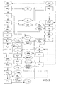
- FIG. 2 schematically shows essential components of the plant for processing the shredder residues and the intermediate or end products accumulating during each of the processes on these components in a flow diagram shown. For clarity, the end products produced during the process are centered.
- the pre-process Before L for the preparation of the shredder light fraction SLF is schematically in the left upper part, the pre-process Before S for processing the shredder heavy fraction SSF in the upper right part, the main process SR H centered in the lower part and the refining process V in the lower left part the drawing shown.
- the shredder heavy fraction SSF is first subjected to a two-stage Fe and V2A separation by means of a permanent magnetic separator PM S 1.
- a classification of the residual stream and a separation of non-ferrous metal-containing fractions NE S is supplied.
- This can be done, for example, such that initially a classification into different fractions, for example, larger and smaller than 20 mm, takes place and this fraction each separately to the metal separator MA S 1 are supplied.
- additional classification levels are conceivable.
- the focus here is on the cleanest possible separation into the non-ferrous metal-containing fractions NE S and the remaining metal-poor fractions NM S.
- the classifier K S 1 further provides that metal-poor fractions NM S are separated with a Kom miciger preferably ⁇ 6 mm in a sand fraction sand S.
- the remaining coarse metal-rich fraction NM S is then separated with a density separation device D S 1 in a heavy material fraction SG S and a high-density residual fraction residue. This is to prevent that in the further treatment of the heavy material fraction SG S in downstream crushing still Friedabrasive and sharp-edged materials, such as stainless steel balls are present in the grinding chamber:
- a metal separator can be installed to last wear-promoting, massive Separate metal contaminants.
- the pre-process before S thus delivers an iron fraction Fe, a steel fraction V2A, a non-ferrous metal-containing fraction NE S , a sand fraction Sand S and a heavy fraction SG S.
- a foam fraction PU - consisting mainly of the easy-flying polyurethane - in the suction AB L 1 separated.
- the separated foam pieces are pneumatically conveyed into a press container and there automatically compressed. This fraction can be recycled directly or, if appropriate, fed to another refining step which is not further elaborated here.
- the remaining fraction is now digested in a first crushing unit Z L 1, in such a way that a discharge of the aggregate Z L 1 contains particles with a diameter ⁇ 50 mm.
- a classifying device not shown here, for separating and feeding a fraction with a diameter of> 50 mm is connected upstream.
- an iron fraction Fe and a steel fraction V2A are separated by means of a permanent magnet separator PM L 1.
- the remaining non-ferromagnetic fraction NF L is now fed to a second crushing unit Z L 2, in which a further digestion of the material takes place.
- a discharge of the crushing unit Z L 2 is designed with ⁇ 10 mm. Again, the loading of the crushing unit Z L 2 can be limited to a fraction with a diameter> 10 mm via a classifier, not shown.
- a fine-grained sand fraction Sand L is separated in a further classifier K L 1.
- a grain size of the sand fraction sand L is preferably set to ⁇ 4 mm.
- the remaining fraction is subjected to air classification and density separation in a corresponding device D L 1.
- a light fraction of lint is blown by means of a cross-flow classifier via a heavy-material flap. Due to the previous promotion on a vibratory conveyor, the heavier material has already settled down, so that the underlying heavy fraction inevitably falls down into a heavy goods discharge (heavy cargo fraction SG L ).
- the final products and intermediates PU foam pieces, iron Fe, V2A steel, sand, sand and heavy L L SG can be provided in the preliminary process before L.
- the heavy metals and organics-containing dusts and sludges occurring during processing in the comminution units Z L 1 and Z L 2 are fed to the residual fraction.
- the sand fractions Sand L , Sand S are combined to form a common sand sand fraction Sand H.
- the raw sand fraction Sand H must be further separated. It is essential that the refined sand fraction Sand v contains sufficiently high levels of oxides of the elements iron, aluminum, silicon and calcium, which can substitute primary raw materials. Furthermore, the concentration of potential process or product contaminants should be kept as low as possible. Depending on the intended use, contaminants of the type mentioned can be, for example, the metals copper, zinc, lead, chromium, but also sodium, potassium and magnesium. Furthermore, the proportion of organics, in particular the proportion of halogen-containing plastics, must be lowered sufficiently. Such a refined sand fraction sand v thus also already meets the requirements of TA municipal waste (requirements from 2005) for a deposited on a municipal waste landfill good.
- a dust fraction NE dust is separated from ultrafine grain and easily airborne organic components by means of an air classifier WS V.
- the dust fraction NE dust in particular contains heavy metal dusts and is fed to the waste fraction for disposal.
- the heavy fraction of the wind sifter WS V is fed to an air-setting table (density separator D V ). There, the separation of a light, organic-rich residual fraction rest org occurs . This can also be discharged directly from the process and combined with the residual fraction residual. Subsequently, the remaining heavy fraction of remaining metallic constituents, mainly non-ferrous metals, is freed in an all-metal separator MA V (non-ferrous metal fraction NE V ). The non-ferrous metal fraction NE V can be transferred to non-ferrous metal processing.
- the raw sand fraction Sand H is separated into a dust fraction NE dust , non-ferrous metal fraction NE V , an organic-rich residual fraction org and an organ- and metal-free sand fraction Sand V.
- the heavy-material fractions SG L and SG S are combined during the main process SR H to form a common heavy-material fraction SG. This is subsequently digested again in a further comminution unit Z H 1.
- a discharge of the crushing units Z H 1 is designed with ⁇ 8 mm.
- the crushing unit Z H 1 is usually designed as a cutting mill, so that at this point an optimal material digestion is achieved.
- a density separation takes place on air-setting tables (density separation device D H 1).
- the separated light fraction consists mainly of plastic in granulated form.
- the granules may optionally continue in an additional refining process be worked up.
- the remaining heavy fraction NE H consists mostly of non-ferrous metals, mainly copper strands.
- the fraction NE H can therefore already be withdrawn from the process at this point, but also be combined with the non-ferrous metal-containing fraction NE S to form a common fraction NE and be processed together.
- the treatment of the non-ferrous metal-containing fraction NE can essentially be effected by means of a sand flotation plant SF1 and an optical sorter OS1.
- a sand flotation plant SF1 and an optical sorter OS1 With a sand floatation, it is possible to dry-mechanically separate a light metal fraction mainly of aluminum Al and magnesium Mg from a heavy metal fraction.
- the sand used here as a separation medium has nothing to do with the separated fraction "sand" from the shredder residues.
- the heavy metals sink into the sand bed, while the light metals float on the sand bed.
- a separating sheath separates a light metal-containing upper stream and the heavy metal-enriched under-stream.
- the metal concentrates are again separated from the separating medium sand.
- the separated aluminum and magnesium fraction Al / Mg can optionally be further separated.
- the separated heavy fraction (especially zinc Zn, copper Cu, brass, lead Pb and possibly V4A steel) is separated by the optical sorter OS1 in non-ferrous metals copper / brass and other metals.
- any nonmetallic radicals which may be present here can be fed in at a suitable point, such as here in the pre-process L ago.
- an Al / Mg fraction, a Cu / brass fraction, a fraction with other metals, a granulate fraction and a raw sand fraction Sand H are provided in the main process SR H with subsequent NF metal treatment.
- the raw sand fraction sand H is - as already explained - further refined in the finishing process V, so that the final product is the organic and metal-free sand fraction sand V obtained.
Landscapes
- Engineering & Computer Science (AREA)
- Chemical & Material Sciences (AREA)
- Materials Engineering (AREA)
- Mechanical Engineering (AREA)
- Geology (AREA)
- General Life Sciences & Earth Sciences (AREA)
- Manufacturing & Machinery (AREA)
- Environmental & Geological Engineering (AREA)
- Life Sciences & Earth Sciences (AREA)
- Organic Chemistry (AREA)
- Metallurgy (AREA)
- Geochemistry & Mineralogy (AREA)
- Processing Of Solid Wastes (AREA)
- Combined Means For Separation Of Solids (AREA)
- Disintegrating Or Milling (AREA)
- Manufacture And Refinement Of Metals (AREA)
Abstract
Claims (25)
- Procédé de préparation de résidus de déchiquetage de déchets qui contiennent des métaux et en particulier les carrosseries de véhicule, dans lequel les résidus de déchiquetage sont séparés en une fraction légère de déchiquetage (SLF) et une fraction non ferromagnétique (fraction lourde de déchiquetage (SSF)), caractérisé en ce que :(a) pendant la préparation de la fraction légère de déchiquetage (SLF) et de la fraction lourde de déchiquetage (SSF) dans des opérations préalables (VorL, VorS) et des écoulements partiels qui sont produits dans les opérations préalables (VorL, VorS), on crée au moins par parties dans une opération principale commune (SRH) une fraction de sable brut (sableH) par séparation d'au moins une fraction ferromagnétique (Fe/V2A), d'une fraction (NF) qui contient des métaux non ferreux, d'une fraction de peluches (peluches) et d'une fraction de granulés (granulés) et(b) dans une opération d'affinage (V) et par des étapes successives de traitement, à savoir une séparation en fonction de la masse spécifique et une séparation des métaux, la fraction de sable brut (sableH) est séparée en une fraction résiduelle riche en substances organiques (restorg), une fraction de poussières de métaux lourds (NFpouss), une fraction de sable pauvre en substances organiques et en métaux (sableV) et une fraction de métaux non ferreux (NFV).
- Procédé selon la revendication 1, caractérisé en ce que la fraction légère de déchiquetage (SLF) subit un pré-traitement supplémentaire au moyen d'un séparateur magnétique en vue de séparer les fractions ferromagnétiques résiduelles.
- Procédé selon les revendications 1 ou 2, caractérisé en ce que dans l'opération préalable (VorL), partant de la fraction légère de déchiquetage (SLF) prétraitée, par déchiquetage, séparation des métaux, classification et séparation en fonction de la densité des fractions ferromagnétiques (Fe/V2A), on sépare une fraction de sable fin (sableL) et une fraction de peluches d'une fraction (SGL) de produits lourds à grains grossiers.
- Procédé selon la revendication 3, caractérisé en ce qu'à partir de la fraction légère de déchiquetage (SLF) prétraitée dans l'opération préalable (VorL), on sépare de plus une fraction de mousse (PU) au moyen d'un dispositif d'aspiration (ABL1).
- Procédé selon la revendication 3, caractérisé en ce que le déchiquetage et la classification fournissent une fraction de produits lourds (SGL) dont le diamètre est de préférence compris entre 4 et 10 mm.
- Procédé selon l'une des revendications 1 à 5, caractérisé en ce qu'à partir de la fraction lourde de déchiquetage (SSF), au cours de l'opération préalable (VorS) et par séparation des métaux, classification et séparation en fonction de la masse spécifique, on sépare d'une fraction de produits lourds (SGS) au moins une fraction (NFS) qui ne contient pas de métaux non ferreux, une fraction de sable fin (sableF) et une fraction résiduelle à haute masse spécifique (rest).
- Procédé selon la revendication 6, caractérisé en ce que la classification fournit une fraction de produits lourds (SGS) dont le diamètre est de préférence > 6 mm.
- Procédé selon l'une des revendications 1 à 7, caractérisé en ce que dans l'opération principale (SRH), les fractions de produits lourds (SGL, SGS) sont désagrégées au moyen d'une machine de déchiquetage (ZH1) et sont séparées au moyen d'un dispositif (DH1) de séparation en fonction de la masse spécifique en une fraction de granulés (granulés) et en une fraction enrichie en métaux non ferreux (NFH).
- Procédé selon la revendication 8, caractérisé en ce que dans l'opération principale (SRH), les fractions de sable (sableL, sables) sont rassemblées en une fraction commune de sable brut (sableH).
- Procédé selon la revendication 8, caractérisé en ce que les fractions (NFH, NFS) qui contiennent des métaux sont rassemblées en une fraction métallifère commune (NF).
- Procédé selon l'une des revendications 1 à 10, caractérisé en ce qu'au moyen d'un dispositif (DV) de séparation en fonction de la masse spécifique, on réalise une séparation de la fraction résiduelle (restorg) qui contient des substances organiques et de la fraction encore présente de sable brut (sableH).
- Procédé selon l'une des revendications 1 à 11, caractérisé en ce que l'on réalise une séparation des métaux de la fraction de sable brut (sableH).
- Procédé selon l'une des revendications 1 à 12, caractérisé en ce que la fraction (NFpouss) de poussières qui contiennent des métaux lourds est séparée avant la séparation en fonction de la masse spécifique.
- Procédé selon l'une des revendications 1 à 13, caractérisé en ce que la fraction (NFV) qui contient des métaux non ferreux et qui est produite lors de la séparation au cours de l'opération d'affinage (V) est intégrée en fonction de sa quantité et de sa composition dans une opération de traitement de la fraction (NF) qui contient des métaux non ferreux.
- Installation de traitement de résidus de déchiquetage de déchets qui contiennent des métaux, en particulier de carrosseries de véhicule, constitués d'une fraction légère de déchiquetage (SLF) et d'une fraction non ferromagnétique (fraction lourde de déchiquetage (SSF)), caractérisée en ce qu'elle présente des moyens avec lesquels :(a) pendant la préparation de la fraction légère de déchiquetage (SLF) et de la fraction lourde de déchiquetage (SSF) dans des opérations préalables (VorL, VorS) et des écoulements partiels qui sont produits dans les opérations préalables (VorL, VorS), on crée au moins par parties dans une opération principale commune (SRH) une fraction de sable brut (sableH) par séparation d'au moins une fraction ferromagnétique (Fe/V2A), d'une fraction (NF) qui contient des métaux non ferreux, d'une fraction de peluches (peluches) et d'une fraction de granulés (granulés) et(b) dans une opération d'affinage (V) et par des étapes successives de traitement, à savoir une séparation en fonction de la masse spécifique et une séparation des métaux, la fraction de sable brut (sableH) est séparée en une fraction résiduelle riche en substances organiques (restorg), une fraction de poussières de métaux lourds (NFpouss), une fraction de sable pauvre en substances organiques et en métaux (sableV) et une fraction de métaux non ferreux (NFV).
- Installation selon la revendication 15, caractérisée en ce qu'un séparateur magnétique est prévu pour séparer des fractions résiduelles ferromagnétiques de la fraction légère de déchiquetage (SLF).
- Installation selon les revendications 15 ou 16, caractérisé en ce que pour le traitement de la fraction légère de déchiquetage (SLF) prétraitée au cours de l'opération préalable (VorL), on prévoit successivement:- une première machine de déchiquetage (ZL1) qui décortique la fraction légère de déchiquetage (SLF),- au moins un séparateur magnétique (PML1) qui sépare au moins une fraction ferromagnétique (Fe, V2A) d'une fraction non ferromagnétique (NFL),- une deuxième machine de déchiquetage (ZL2) qui décortique la fraction non ferromagnétique (NFL),- au moins un dispositif de classification (KL1) qui sépare une fraction de sable fin (sableL) et- au moins un dispositif (DL1) de séparation en fonction de la masse spécifique qui sépare la fraction résiduelle en la fraction de peluches (peluches) et une fraction (SGL) de produits lourds à grains grossiers.
- Installation selon la revendication 17, caractérisée en ce qu'elle présente de plus un dispositif d'aspiration (ABL1) qui sépare une fraction de mousse (PU).
- Installation selon l'une des revendications 15 à 18, caractérisée en ce que pour traiter la fraction lourde de déchiquetage (SSF) dans l'opération préalable (VorS), on prévoit successivement un séparateur de métaux (MAS1) et au moins un dispositif de classification (KS1) qui séparent au moins une fraction (NFS) qui est enrichie en métaux non ferreux, une fraction (SGS) de produits lourds et une fraction de sable fin appauvri en métaux (sableS).
- Installation selon l'une des revendications 15 à 19, caractérisée en ce que pour traiter les écoulements de matière qui proviennent des opérations préalables (VorL, VorS), on prévoit dans l'opération principale (SRH) :- des moyens qui rassemblent les fractions dé sable (sableL, sableS) en une fraction commune de sable brut (sableH),- des moyens qui rassemblent les fractions (SGL, SGS) de produits lourds en une fraction commune (SG) de produits lourds,- une machine de déchiquetage (ZH1) qui décortique la fraction (SG) de produits lourds et ensuite- un dispositif (DH1) de séparation en fonction de la masse spécifique qui sépare la fraction des granulés (granulés) et une fraction (NFH) enrichie en métaux non ferreux de la fraction décortiquée (SG) de produits lourds.
- Installation selon l'une des revendications 15 à 20, caractérisée en ce que les moyens de traitement de la fraction de sable brut (sableH) dans l'opération d'affinage (V) comprennent un dispositif (DV) de séparation en fonction de la masse spécifique et un séparateur (MAV) de tous les métaux.
- Installation selon la revendication 21, caractérisée en ce qu'elle présente de plus un séparateur aéraulique (WSV) qui sépare une fraction de poussières (NFpouss).
- Installation selon la revendication 21, caractérisée en ce qu'elle présente des moyens d'entreposage de la fraction (NFV) qui contient des métaux non ferreux et qui est produite lors de la séparation au cours de l'opération d'affinage (V) dans une opération de traitement de la fraction (NF) qui contient des métaux non ferreux.
- Utilisation du procédé de traitement de sable brut provenant de déchets métallifères de résidus de déchiquetage, en particulier de carrosseries de véhicule, selon l'une des revendications 1 à 14, caractérisée en ce que l'on y sépare une fraction de sable (sableV) pauvre en métaux et en substances organiques pour l'utiliser comme matière première d'additifs de cimenterie, d'installations de frittage, de hauts-fourneaux ou comme additif pour la fabrication de briques de maçonnerie en briqueterie, mais qui satisfait les spécifications futures ("TA Siedlungsabfall" à partir de 2005) en matière de mise en décharge des déchets urbains.
- Utilisation selon la revendication 24, caractérisée en ce que la fraction de sable (sableV) présente au moins les caractéristiques suivantes:- une perte au feu < 30% en poids,- une teneur en carbone organique < 18% en poids,- une teneur en Cl < 1,5% en poids,- une teneur en Zn < 1,0% en poids,- une teneur en Cu < 0,2% en poids et- une teneur en Pb < 0,1% en poids.
Priority Applications (1)
| Application Number | Priority Date | Filing Date | Title |
|---|---|---|---|
| EP20060017838 EP1721677B1 (fr) | 2000-10-27 | 2001-09-18 | Procédé pour traiter des résidus de déchiquetage pour la production d'une fraction de sable |
Applications Claiming Priority (3)
| Application Number | Priority Date | Filing Date | Title |
|---|---|---|---|
| DE10053492 | 2000-10-27 | ||
| DE10053492A DE10053492A1 (de) | 2000-10-27 | 2000-10-27 | Anlage und Verfahren zur Aufbereitung von Shredder-Rückständen und Verwendung einer erzeugten Sand-Fraktion |
| PCT/EP2001/010762 WO2002034402A1 (fr) | 2000-10-27 | 2001-09-18 | Installation et procede pour traiter des residus de dechiquetage et utilisation d'une fraction de sable ainsi produite |
Related Child Applications (1)
| Application Number | Title | Priority Date | Filing Date |
|---|---|---|---|
| EP20060017838 Division EP1721677B1 (fr) | 2000-10-27 | 2001-09-18 | Procédé pour traiter des résidus de déchiquetage pour la production d'une fraction de sable |
Publications (2)
| Publication Number | Publication Date |
|---|---|
| EP1332002A1 EP1332002A1 (fr) | 2003-08-06 |
| EP1332002B1 true EP1332002B1 (fr) | 2007-02-28 |
Family
ID=7661382
Family Applications (2)
| Application Number | Title | Priority Date | Filing Date |
|---|---|---|---|
| EP20060017838 Expired - Lifetime EP1721677B1 (fr) | 2000-10-27 | 2001-09-18 | Procédé pour traiter des résidus de déchiquetage pour la production d'une fraction de sable |
| EP20010976232 Expired - Lifetime EP1332002B1 (fr) | 2000-10-27 | 2001-09-18 | Installation et procede pour traiter des residus de dechiquetage et utilisation d'une fraction de sable ainsi produite |
Family Applications Before (1)
| Application Number | Title | Priority Date | Filing Date |
|---|---|---|---|
| EP20060017838 Expired - Lifetime EP1721677B1 (fr) | 2000-10-27 | 2001-09-18 | Procédé pour traiter des résidus de déchiquetage pour la production d'une fraction de sable |
Country Status (8)
| Country | Link |
|---|---|
| US (1) | US7389880B2 (fr) |
| EP (2) | EP1721677B1 (fr) |
| JP (1) | JP4931325B2 (fr) |
| CN (1) | CN1188220C (fr) |
| AT (3) | ATE497410T1 (fr) |
| DE (3) | DE10053492A1 (fr) |
| ES (2) | ES2359578T3 (fr) |
| WO (1) | WO2002034402A1 (fr) |
Families Citing this family (17)
| Publication number | Priority date | Publication date | Assignee | Title |
|---|---|---|---|---|
| DE10053488A1 (de) * | 2000-10-27 | 2002-05-08 | Volkswagen Ag | Anlage und Verfahren zur Aufbereitung von Shredder-Rückständen und Verwendung einer erzeugten Granulat-Fraktion |
| DE10053487A1 (de) * | 2000-10-27 | 2002-05-08 | Volkswagen Ag | Anlage und Verfahren zur Aufbereitung von Shredder-Rückständen |
| DE10053491A1 (de) * | 2000-10-27 | 2002-05-08 | Volkswagen Ag | Anlage und Verfahren zur Aufbereitung von Shredder-Rückständen und Verfahren einer erzeugten Flusen-Fraktion |
| US7264124B2 (en) | 2003-11-17 | 2007-09-04 | Casella Waste Systems, Inc. | Systems and methods for sorting recyclables at a material recovery facility |
| US7757863B2 (en) | 2003-11-17 | 2010-07-20 | Casella Waste Systems, Inc. | Systems and methods for glass recycling at a beneficiator and/or a material recovery facility |
| JP2008519753A (ja) | 2004-11-12 | 2008-06-12 | カセラ ウェイスト システムズ インコーポレーティッド | 混色カレットの特長づけおよび確認を行い、一様に着色された混入物のない混色カレットを提供するためのシステムおよび方法 |
| AT504885B1 (de) * | 2007-05-21 | 2008-09-15 | Univ Wien Tech | Verfahren zur herstellung eines zuschlagstoffs für die herstellung von baumaterialien |
| US8459466B2 (en) | 2007-05-23 | 2013-06-11 | Re Community Energy, Llc | Systems and methods for optimizing a single-stream materials recovery facility |
| DE102008063047A1 (de) * | 2008-12-23 | 2010-06-24 | Volkswagen Ag | Verfahren zur Aufbereitung einer textilen Fraktion, welche bei der Aufbereitung von Altreifen erzeugt wurde sowie Anlage zur Durchführung des Verfahrens |
| FR2962924B1 (fr) | 2010-07-22 | 2012-08-03 | Recypatents | Procede et dispositif de traitement de dechets, notamment de residus de broyage legers |
| US9132432B2 (en) * | 2011-10-15 | 2015-09-15 | Dean Andersen Trust | Isotropic quantization sorting systems of automobile shredder residue to enhance recovery of recyclable materials |
| DE102012203333A1 (de) | 2012-03-02 | 2013-09-05 | Sicon Gmbh | Verfahren und Anlage zur Aufbereitung metallhaltigen Schrotts |
| ITUB20153608A1 (it) * | 2015-09-14 | 2017-03-14 | Danieli Off Mecc | Impianto e metodo di recupero e trattamento di residui di frantumazione di rottami ferrosi |
| CN106903138A (zh) * | 2017-04-06 | 2017-06-30 | 环创(厦门)科技股份有限公司 | 大件垃圾破碎分选设备及工艺 |
| US10835927B2 (en) | 2018-11-29 | 2020-11-17 | Wm Intellectual Property Holdings Llc | System and process for sorting and recovery of recyclable materials from mixed waste |
| CN112619854A (zh) * | 2020-12-25 | 2021-04-09 | 日昌升建筑新材料设计研究院有限公司 | 一种柔性高端机制砂石干法生产工艺 |
| US11707747B1 (en) | 2021-08-05 | 2023-07-25 | Wm Intellectual Property Holdings, L.L.C. | System and process for sorting and recovery of recyclable materials from mixed municipal solid waste |
Family Cites Families (19)
| Publication number | Priority date | Publication date | Assignee | Title |
|---|---|---|---|---|
| NL181177C (nl) * | 1975-03-29 | 1987-07-01 | Stamicarbon | Werkwijze voor het terugwinnen van bruikbare materialen uit afvalmateriaal dat metalen en niet-metalen bevat. |
| US5080291A (en) * | 1989-10-30 | 1992-01-14 | Bloom Dennis R | Method of recycling automobile waste residue |
| DE4205309A1 (de) * | 1992-02-21 | 1993-08-26 | Preussag Ag | Verfahren zur aufbereitung von reststoffen aus altautomobilen |
| US5535891A (en) * | 1993-08-18 | 1996-07-16 | Nippon Jiryoku Senko Co., Ltd. | Method of processing scraps and equipment therefor |
| US5443157A (en) * | 1994-03-31 | 1995-08-22 | Nimco Shredding Co. | Automobile shredder residue (ASR) separation and recycling system |
| DE4437852A1 (de) | 1994-10-22 | 1996-05-02 | Heckett Multiserv Plc | Verfahren zum Aufbereiten von Shredderrückständen |
| AU3765497A (en) | 1996-07-10 | 1998-02-02 | Guschall, Dietmar | Process and system for treatment of mixed plastic materials |
| DE19703577A1 (de) * | 1996-11-30 | 1998-06-04 | Rudolf Engel | Verfahren und Anlage zum Behandeln einer Shredder-Leichtfraktion aus LKW- und PKW-Schrott |
| EP0863114A1 (fr) | 1997-03-05 | 1998-09-09 | Michael Bäumer | Matériau à plasticité permanente pour le remblayage de mines utilisant des fractions légères de déchiquetage |
| DE19724860A1 (de) | 1997-06-12 | 1998-12-17 | Krc Umwelttechnik Gmbh | Verfahren und Vorrichtung zur Aufbereitung einer Shredderleichtfraktion mit Metallteilen |
| DE19731874C1 (de) | 1997-07-24 | 1999-02-11 | Krupp Uhde Gmbh | Verfahren zur thermischen Verwertung von kunststoffhaltigen Abfallstoffen, insbesondere aus der Altkraftfahrzeug-Verwertung |
| DE19742214C2 (de) | 1997-09-24 | 2000-04-27 | Nymic Anstalt Schaan | Verfahren zur Verwertung von Altautos |
| AT408684B (de) | 1997-12-11 | 2002-02-25 | Holderbank Financ Glarus | Verfahren zum aufarbeiten von rest-shredder oder von shredderleichtfraktionen |
| DE19755629A1 (de) | 1997-12-15 | 1999-06-24 | Uwh Ges Fuer Thermische Ruecks | Verfahren zur Aufbereitung der Shredderleichtfraktion aus Shredderanlagen |
| JP3541127B2 (ja) * | 1998-08-13 | 2004-07-07 | エンヴィテック株式会社 | シュレッダーダストの処理方法 |
| JP2000135450A (ja) * | 1998-10-30 | 2000-05-16 | Mitsubishi Electric Corp | 破砕装置及び選別処理装置及び破砕方法及び選別処理方法 |
| DE19911010A1 (de) * | 1999-03-12 | 2000-10-05 | Georg Schons | Anlage und Verfahren für die Verwendung von Shredderabfällen o. dgl. Verbundstoffen sowie Verwendung einer Rotorprallmühle |
| US6666335B1 (en) * | 1999-10-29 | 2003-12-23 | C.A.S.T. Minerals, Inc. | Multi-mineral/ash benefication process and apparatus |
| US6422493B1 (en) * | 2000-06-01 | 2002-07-23 | Simon Family Partners | Method and apparatus for sorting recyclable products |
-
2000
- 2000-10-27 DE DE10053492A patent/DE10053492A1/de not_active Withdrawn
-
2001
- 2001-09-18 AT AT06017838T patent/ATE497410T1/de active
- 2001-09-18 WO PCT/EP2001/010762 patent/WO2002034402A1/fr not_active Ceased
- 2001-09-18 CN CNB018148034A patent/CN1188220C/zh not_active Expired - Lifetime
- 2001-09-18 AT AT01976232T patent/ATE355132T1/de active
- 2001-09-18 EP EP20060017838 patent/EP1721677B1/fr not_active Expired - Lifetime
- 2001-09-18 DE DE50115790T patent/DE50115790D1/de not_active Expired - Lifetime
- 2001-09-18 ES ES06017838T patent/ES2359578T3/es not_active Expired - Lifetime
- 2001-09-18 JP JP2002537440A patent/JP4931325B2/ja not_active Expired - Fee Related
- 2001-09-18 ES ES01976232T patent/ES2280403T3/es not_active Expired - Lifetime
- 2001-09-18 US US10/415,505 patent/US7389880B2/en not_active Expired - Lifetime
- 2001-09-18 DE DE50112135T patent/DE50112135D1/de not_active Expired - Lifetime
- 2001-09-18 EP EP20010976232 patent/EP1332002B1/fr not_active Expired - Lifetime
-
2006
- 2006-03-31 AT AT0025306U patent/AT8506U1/de not_active IP Right Cessation
Also Published As
| Publication number | Publication date |
|---|---|
| DE50112135D1 (de) | 2007-04-12 |
| CN1449308A (zh) | 2003-10-15 |
| EP1721677B1 (fr) | 2011-02-02 |
| CN1188220C (zh) | 2005-02-09 |
| US7389880B2 (en) | 2008-06-24 |
| DE10053492A1 (de) | 2002-05-08 |
| ES2280403T3 (es) | 2007-09-16 |
| WO2002034402A1 (fr) | 2002-05-02 |
| EP1721677A2 (fr) | 2006-11-15 |
| AT8506U1 (de) | 2006-09-15 |
| DE50115790D1 (de) | 2011-03-17 |
| US20040251173A1 (en) | 2004-12-16 |
| ATE497410T1 (de) | 2011-02-15 |
| ES2359578T3 (es) | 2011-05-24 |
| EP1332002A1 (fr) | 2003-08-06 |
| EP1721677A3 (fr) | 2008-04-23 |
| JP2004512170A (ja) | 2004-04-22 |
| JP4931325B2 (ja) | 2012-05-16 |
| ATE355132T1 (de) | 2006-03-15 |
Similar Documents
| Publication | Publication Date | Title |
|---|---|---|
| EP1337341B1 (fr) | Installation et procede pour traiter des residus de dechiquetage | |
| EP1332002B1 (fr) | Installation et procede pour traiter des residus de dechiquetage et utilisation d'une fraction de sable ainsi produite | |
| EP1332001B1 (fr) | Installation et procede pour traiter des residus de dechiquetage et utilisation d'une fraction de granulat ainsi produite | |
| EP1333931B1 (fr) | Installation et procede de traitement de residus de dechiquetage et utilisation d'une fraction de dechiquetage produite | |
| EP2271430B1 (fr) | Procédé et installation pour le traitement de déchets de matières plastiques | |
| DE19911010A1 (de) | Anlage und Verfahren für die Verwendung von Shredderabfällen o. dgl. Verbundstoffen sowie Verwendung einer Rotorprallmühle | |
| DE19755629A1 (de) | Verfahren zur Aufbereitung der Shredderleichtfraktion aus Shredderanlagen | |
| DE102004045821B4 (de) | Verfahren und Anlage zur Aufbereitung der Schredderleichtfraktion aus der Zerkleinerung von Schrotten und metallischen Abfällen | |
| DE10334646B4 (de) | Verfahren und Anlage zur Aufbereitung der Shredderleichtfraktion aus der Zerkleinerung von Schrotten und metallhaltigen Abfällen | |
| EP2254701B1 (fr) | Procédé et installation pour le traitement de déchets de matières plastiques à faible teneur en métaux | |
| EP1656995A1 (fr) | Procédé pour l'utilisation de déchets broyés |
Legal Events
| Date | Code | Title | Description |
|---|---|---|---|
| PUAI | Public reference made under article 153(3) epc to a published international application that has entered the european phase |
Free format text: ORIGINAL CODE: 0009012 |
|
| 17P | Request for examination filed |
Effective date: 20030527 |
|
| AK | Designated contracting states |
Designated state(s): AT BE CH CY DE DK ES FI FR GB GR IE IT LI LU MC NL PT SE TR |
|
| RIN1 | Information on inventor provided before grant (corrected) |
Inventor name: KNUST, MICHAEL Inventor name: DEN DUNNEN, BRAM Inventor name: GOLDMANN, DANIEL |
|
| GRAP | Despatch of communication of intention to grant a patent |
Free format text: ORIGINAL CODE: EPIDOSNIGR1 |
|
| GRAS | Grant fee paid |
Free format text: ORIGINAL CODE: EPIDOSNIGR3 |
|
| GRAA | (expected) grant |
Free format text: ORIGINAL CODE: 0009210 |
|
| AK | Designated contracting states |
Kind code of ref document: B1 Designated state(s): AT BE CH CY DE DK ES FI FR GB GR IE IT LI LU MC NL PT SE TR |
|
| PG25 | Lapsed in a contracting state [announced via postgrant information from national office to epo] |
Ref country code: IE Free format text: LAPSE BECAUSE OF FAILURE TO SUBMIT A TRANSLATION OF THE DESCRIPTION OR TO PAY THE FEE WITHIN THE PRESCRIBED TIME-LIMIT Effective date: 20070228 Ref country code: FI Free format text: LAPSE BECAUSE OF FAILURE TO SUBMIT A TRANSLATION OF THE DESCRIPTION OR TO PAY THE FEE WITHIN THE PRESCRIBED TIME-LIMIT Effective date: 20070228 Ref country code: DK Free format text: LAPSE BECAUSE OF FAILURE TO SUBMIT A TRANSLATION OF THE DESCRIPTION OR TO PAY THE FEE WITHIN THE PRESCRIBED TIME-LIMIT Effective date: 20070228 |
|
| REG | Reference to a national code |
Ref country code: GB Ref legal event code: FG4D Free format text: NOT ENGLISH |
|
| REG | Reference to a national code |
Ref country code: CH Ref legal event code: EP |
|
| REF | Corresponds to: |
Ref document number: 50112135 Country of ref document: DE Date of ref document: 20070412 Kind code of ref document: P |
|
| REG | Reference to a national code |
Ref country code: IE Ref legal event code: FG4D Free format text: LANGUAGE OF EP DOCUMENT: GERMAN |
|
| REG | Reference to a national code |
Ref country code: SE Ref legal event code: TRGR |
|
| GBT | Gb: translation of ep patent filed (gb section 77(6)(a)/1977) |
Effective date: 20070503 |
|
| ET | Fr: translation filed | ||
| PG25 | Lapsed in a contracting state [announced via postgrant information from national office to epo] |
Ref country code: PT Free format text: LAPSE BECAUSE OF FAILURE TO SUBMIT A TRANSLATION OF THE DESCRIPTION OR TO PAY THE FEE WITHIN THE PRESCRIBED TIME-LIMIT Effective date: 20070730 |
|
| REG | Reference to a national code |
Ref country code: ES Ref legal event code: FG2A Ref document number: 2280403 Country of ref document: ES Kind code of ref document: T3 |
|
| REG | Reference to a national code |
Ref country code: IE Ref legal event code: FD4D |
|
| PLBE | No opposition filed within time limit |
Free format text: ORIGINAL CODE: 0009261 |
|
| STAA | Information on the status of an ep patent application or granted ep patent |
Free format text: STATUS: NO OPPOSITION FILED WITHIN TIME LIMIT |
|
| 26N | No opposition filed |
Effective date: 20071129 |
|
| PG25 | Lapsed in a contracting state [announced via postgrant information from national office to epo] |
Ref country code: MC Free format text: LAPSE BECAUSE OF NON-PAYMENT OF DUE FEES Effective date: 20070930 Ref country code: GR Free format text: LAPSE BECAUSE OF FAILURE TO SUBMIT A TRANSLATION OF THE DESCRIPTION OR TO PAY THE FEE WITHIN THE PRESCRIBED TIME-LIMIT Effective date: 20070529 |
|
| PG25 | Lapsed in a contracting state [announced via postgrant information from national office to epo] |
Ref country code: CY Free format text: LAPSE BECAUSE OF FAILURE TO SUBMIT A TRANSLATION OF THE DESCRIPTION OR TO PAY THE FEE WITHIN THE PRESCRIBED TIME-LIMIT Effective date: 20070228 |
|
| PG25 | Lapsed in a contracting state [announced via postgrant information from national office to epo] |
Ref country code: LU Free format text: LAPSE BECAUSE OF NON-PAYMENT OF DUE FEES Effective date: 20070918 |
|
| PG25 | Lapsed in a contracting state [announced via postgrant information from national office to epo] |
Ref country code: TR Free format text: LAPSE BECAUSE OF FAILURE TO SUBMIT A TRANSLATION OF THE DESCRIPTION OR TO PAY THE FEE WITHIN THE PRESCRIBED TIME-LIMIT Effective date: 20070228 |
|
| REG | Reference to a national code |
Ref country code: FR Ref legal event code: PLFP Year of fee payment: 15 |
|
| REG | Reference to a national code |
Ref country code: FR Ref legal event code: PLFP Year of fee payment: 16 |
|
| REG | Reference to a national code |
Ref country code: FR Ref legal event code: PLFP Year of fee payment: 17 |
|
| PGFP | Annual fee paid to national office [announced via postgrant information from national office to epo] |
Ref country code: IT Payment date: 20170926 Year of fee payment: 17 Ref country code: CH Payment date: 20170925 Year of fee payment: 17 Ref country code: GB Payment date: 20170929 Year of fee payment: 17 |
|
| PGFP | Annual fee paid to national office [announced via postgrant information from national office to epo] |
Ref country code: NL Payment date: 20170925 Year of fee payment: 17 Ref country code: SE Payment date: 20170926 Year of fee payment: 17 Ref country code: BE Payment date: 20170925 Year of fee payment: 17 Ref country code: AT Payment date: 20170928 Year of fee payment: 17 |
|
| PGFP | Annual fee paid to national office [announced via postgrant information from national office to epo] |
Ref country code: FR Payment date: 20171002 Year of fee payment: 17 |
|
| PGFP | Annual fee paid to national office [announced via postgrant information from national office to epo] |
Ref country code: ES Payment date: 20171025 Year of fee payment: 17 |
|
| REG | Reference to a national code |
Ref country code: CH Ref legal event code: PL Ref country code: SE Ref legal event code: EUG |
|
| REG | Reference to a national code |
Ref country code: NL Ref legal event code: MM Effective date: 20181001 |
|
| REG | Reference to a national code |
Ref country code: AT Ref legal event code: MM01 Ref document number: 355132 Country of ref document: AT Kind code of ref document: T Effective date: 20180918 |
|
| GBPC | Gb: european patent ceased through non-payment of renewal fee |
Effective date: 20180918 |
|
| PG25 | Lapsed in a contracting state [announced via postgrant information from national office to epo] |
Ref country code: SE Free format text: LAPSE BECAUSE OF NON-PAYMENT OF DUE FEES Effective date: 20180919 |
|
| REG | Reference to a national code |
Ref country code: BE Ref legal event code: MM Effective date: 20180930 |
|
| PG25 | Lapsed in a contracting state [announced via postgrant information from national office to epo] |
Ref country code: NL Free format text: LAPSE BECAUSE OF NON-PAYMENT OF DUE FEES Effective date: 20181001 |
|
| PG25 | Lapsed in a contracting state [announced via postgrant information from national office to epo] |
Ref country code: IT Free format text: LAPSE BECAUSE OF NON-PAYMENT OF DUE FEES Effective date: 20180918 |
|
| PG25 | Lapsed in a contracting state [announced via postgrant information from national office to epo] |
Ref country code: LI Free format text: LAPSE BECAUSE OF NON-PAYMENT OF DUE FEES Effective date: 20180930 Ref country code: FR Free format text: LAPSE BECAUSE OF NON-PAYMENT OF DUE FEES Effective date: 20180930 Ref country code: BE Free format text: LAPSE BECAUSE OF NON-PAYMENT OF DUE FEES Effective date: 20180930 Ref country code: CH Free format text: LAPSE BECAUSE OF NON-PAYMENT OF DUE FEES Effective date: 20180930 |
|
| PG25 | Lapsed in a contracting state [announced via postgrant information from national office to epo] |
Ref country code: AT Free format text: LAPSE BECAUSE OF NON-PAYMENT OF DUE FEES Effective date: 20180918 Ref country code: GB Free format text: LAPSE BECAUSE OF NON-PAYMENT OF DUE FEES Effective date: 20180918 |
|
| REG | Reference to a national code |
Ref country code: ES Ref legal event code: FD2A Effective date: 20191031 |
|
| PG25 | Lapsed in a contracting state [announced via postgrant information from national office to epo] |
Ref country code: ES Free format text: LAPSE BECAUSE OF NON-PAYMENT OF DUE FEES Effective date: 20180919 |
|
| PGFP | Annual fee paid to national office [announced via postgrant information from national office to epo] |
Ref country code: DE Payment date: 20200930 Year of fee payment: 20 |
|
| REG | Reference to a national code |
Ref country code: DE Ref legal event code: R071 Ref document number: 50112135 Country of ref document: DE |